EP4044618B1 - Tonwiedergabesystem - Google Patents
Tonwiedergabesystem Download PDFInfo
- Publication number
- EP4044618B1 EP4044618B1 EP22155354.8A EP22155354A EP4044618B1 EP 4044618 B1 EP4044618 B1 EP 4044618B1 EP 22155354 A EP22155354 A EP 22155354A EP 4044618 B1 EP4044618 B1 EP 4044618B1
- Authority
- EP
- European Patent Office
- Prior art keywords
- loudspeaker box
- supporting structure
- longitudinal axis
- conductive track
- connection circuit
- Prior art date
- Legal status (The legal status is an assumption and is not a legal conclusion. Google has not performed a legal analysis and makes no representation as to the accuracy of the status listed.)
- Active
Links
Images


Classifications
-
- H—ELECTRICITY
- H04—ELECTRIC COMMUNICATION TECHNIQUE
- H04R—LOUDSPEAKERS, MICROPHONES, GRAMOPHONE PICK-UPS OR LIKE ACOUSTIC ELECTROMECHANICAL TRANSDUCERS; DEAF-AID SETS; PUBLIC ADDRESS SYSTEMS
- H04R1/00—Details of transducers, loudspeakers or microphones
- H04R1/02—Casings; Cabinets ; Supports therefor; Mountings therein
- H04R1/025—Arrangements for fixing loudspeaker transducers, e.g. in a box, furniture
-
- H—ELECTRICITY
- H04—ELECTRIC COMMUNICATION TECHNIQUE
- H04R—LOUDSPEAKERS, MICROPHONES, GRAMOPHONE PICK-UPS OR LIKE ACOUSTIC ELECTROMECHANICAL TRANSDUCERS; DEAF-AID SETS; PUBLIC ADDRESS SYSTEMS
- H04R1/00—Details of transducers, loudspeakers or microphones
- H04R1/02—Casings; Cabinets ; Supports therefor; Mountings therein
- H04R1/026—Supports for loudspeaker casings
-
- H—ELECTRICITY
- H04—ELECTRIC COMMUNICATION TECHNIQUE
- H04R—LOUDSPEAKERS, MICROPHONES, GRAMOPHONE PICK-UPS OR LIKE ACOUSTIC ELECTROMECHANICAL TRANSDUCERS; DEAF-AID SETS; PUBLIC ADDRESS SYSTEMS
- H04R1/00—Details of transducers, loudspeakers or microphones
- H04R1/20—Arrangements for obtaining desired frequency or directional characteristics
- H04R1/22—Arrangements for obtaining desired frequency or directional characteristics for obtaining desired frequency characteristic only
- H04R1/28—Transducer mountings or enclosures modified by provision of mechanical or acoustic impedances, e.g. resonator, damping means
- H04R1/2807—Enclosures comprising vibrating or resonating arrangements
- H04R1/283—Enclosures comprising vibrating or resonating arrangements using a passive diaphragm
- H04R1/2834—Enclosures comprising vibrating or resonating arrangements using a passive diaphragm for loudspeaker transducers
-
- H—ELECTRICITY
- H04—ELECTRIC COMMUNICATION TECHNIQUE
- H04R—LOUDSPEAKERS, MICROPHONES, GRAMOPHONE PICK-UPS OR LIKE ACOUSTIC ELECTROMECHANICAL TRANSDUCERS; DEAF-AID SETS; PUBLIC ADDRESS SYSTEMS
- H04R1/00—Details of transducers, loudspeakers or microphones
- H04R1/20—Arrangements for obtaining desired frequency or directional characteristics
- H04R1/32—Arrangements for obtaining desired frequency or directional characteristics for obtaining desired directional characteristic only
- H04R1/323—Arrangements for obtaining desired frequency or directional characteristics for obtaining desired directional characteristic only for loudspeakers
-
- H—ELECTRICITY
- H04—ELECTRIC COMMUNICATION TECHNIQUE
- H04R—LOUDSPEAKERS, MICROPHONES, GRAMOPHONE PICK-UPS OR LIKE ACOUSTIC ELECTROMECHANICAL TRANSDUCERS; DEAF-AID SETS; PUBLIC ADDRESS SYSTEMS
- H04R3/00—Circuits for transducers, loudspeakers or microphones
- H04R3/12—Circuits for transducers, loudspeakers or microphones for distributing signals to two or more loudspeakers
-
- H—ELECTRICITY
- H04—ELECTRIC COMMUNICATION TECHNIQUE
- H04R—LOUDSPEAKERS, MICROPHONES, GRAMOPHONE PICK-UPS OR LIKE ACOUSTIC ELECTROMECHANICAL TRANSDUCERS; DEAF-AID SETS; PUBLIC ADDRESS SYSTEMS
- H04R1/00—Details of transducers, loudspeakers or microphones
- H04R1/20—Arrangements for obtaining desired frequency or directional characteristics
- H04R1/22—Arrangements for obtaining desired frequency or directional characteristics for obtaining desired frequency characteristic only
- H04R1/28—Transducer mountings or enclosures modified by provision of mechanical or acoustic impedances, e.g. resonator, damping means
- H04R1/2807—Enclosures comprising vibrating or resonating arrangements
-
- H—ELECTRICITY
- H04—ELECTRIC COMMUNICATION TECHNIQUE
- H04R—LOUDSPEAKERS, MICROPHONES, GRAMOPHONE PICK-UPS OR LIKE ACOUSTIC ELECTROMECHANICAL TRANSDUCERS; DEAF-AID SETS; PUBLIC ADDRESS SYSTEMS
- H04R2201/00—Details of transducers, loudspeakers or microphones covered by H04R1/00 but not provided for in any of its subgroups
- H04R2201/02—Details casings, cabinets or mounting therein for transducers covered by H04R1/02 but not provided for in any of its subgroups
- H04R2201/025—Transducer mountings or cabinet supports enabling variable orientation of transducer of cabinet
-
- H—ELECTRICITY
- H04—ELECTRIC COMMUNICATION TECHNIQUE
- H04R—LOUDSPEAKERS, MICROPHONES, GRAMOPHONE PICK-UPS OR LIKE ACOUSTIC ELECTROMECHANICAL TRANSDUCERS; DEAF-AID SETS; PUBLIC ADDRESS SYSTEMS
- H04R2201/00—Details of transducers, loudspeakers or microphones covered by H04R1/00 but not provided for in any of its subgroups
- H04R2201/40—Details of arrangements for obtaining desired directional characteristic by combining a number of identical transducers covered by H04R1/40 but not provided for in any of its subgroups
- H04R2201/401—2D or 3D arrays of transducers
-
- H—ELECTRICITY
- H04—ELECTRIC COMMUNICATION TECHNIQUE
- H04R—LOUDSPEAKERS, MICROPHONES, GRAMOPHONE PICK-UPS OR LIKE ACOUSTIC ELECTROMECHANICAL TRANSDUCERS; DEAF-AID SETS; PUBLIC ADDRESS SYSTEMS
- H04R2420/00—Details of connection covered by H04R, not provided for in its groups
- H04R2420/09—Applications of special connectors, e.g. USB, XLR, in loudspeakers, microphones or headphones
Definitions
- the field of the invention is that of sound reproduction systems and, more specifically, loudspeaker boxes.
- patent document US6374942B1 discloses a system for mechanically and electrically connecting a loudspeaker box to a supporting structure where the loudspeaker box and the supporting structure are electrically coupled to each other in such a way as to allow full rotation of the loudspeaker box in relation to the supporting structure.
- the system comprises a first shell that is fixed to the supporting structure and a second shell that is fixed to the loudspeaker box, the two shells being configured to be interconnected; the shells make the structure considerably complex and occupy a relatively large amount of space.
- the electrical connection is made by connectors that are not very reliable and have a tendency to be disconnected.
- the aim of this disclosure is to provide a sound reproduction system according to claim 1, a loudspeaker box (i.e. a loudspeaker) according to claim 13 and a method for connecting a loudspeaker box to a supporting structure according to claim 14 to overcome at least one of the above mentioned disadvantages of the prior art.
- a loudspeaker box i.e. a loudspeaker
- a method for connecting a loudspeaker box to a supporting structure according to claim 14 to overcome at least one of the above mentioned disadvantages of the prior art.
- the loudspeaker box is mechanically connected to the supporting structure. More specifically, in an embodiment, the cabinet is mechanically connected to the supporting structure, or is mounted on the supporting structure.
- the loudspeaker box includes a connection circuit, which is operatively electrically connected to the distribution circuit of the supporting structure and is configured to receive a signal from the distribution circuit and to transmit it to the sound transducer (or to the motor) to make the vibrating membrane vibrate.
- the connection circuit is also configured to receive an electrical power supply from the distribution circuit of the supporting structure and to transmit it to the sound transducer (or to the motor).
- the sound transducer and the connection circuit are positioned at opposite ends of the self-same loudspeaker box, with respect to a longitudinal axis.
- the sound transducer and the connection circuit form an operating structure of the loudspeaker box.
- the operating structure of the loudspeaker box has a rotational symmetry with respect to the longitudinal axis.
- the present disclosure provides two embodiments.
- the (each) loudspeaker box is provided with a dedicated (respective) cabinet; in this case, the cabinet is preferably part of the operating structure of the loudspeaker box, which exhibits a rotational symmetry with respect to the longitudinal axis.
- a plurality of loudspeaker boxes shares one same cabinet; in this case, the cabinet does not form part of the operating structure of the loudspeaker box which exhibits the rotational symmetry with respect to the longitudinal axis.
- connection circuit of the loudspeaker box is connectable (that is, it is configured for being operatively connected) to the distribution circuit of the supporting structure at a plurality of angular positions, rotated in relation to each other around the longitudinal axis.
- connection circuit of the loudspeaker box and the distribution circuit of the supporting structure are configured to maintain electrical continuity during a rotation (preferably complete) of the loudspeaker box relative to the supporting structure about the longitudinal axis.
- complete rotation is meant a rotation through 360°, hence through an infinite plurality of angular positions.
- the loudspeaker box can be rotated around the longitudinal axis among a plurality of angular positions, while the sound transducer and the connection circuit (thus the operating structure) of the loudspeaker box remain oriented along the longitudinal axis.
- the cabinet rotates as one with the loudspeaker box; instead, in the embodiment where the cabinet is common to a plurality of loudspeaker boxes, the cabinet remains stationary during the rotation of the loudspeaker box.
- first and second conductive tracks running all the way around the longitudinal axis and oriented in a plane perpendicular to the longitudinal axis (or in two or more planes perpendicular to the longitudinal axis) makes the electrical connection independent of the relative angular position of the loudspeaker box in relation to the supporting structure and is, at the same time, a practical, simple and reliable system.
- the loudspeaker box is movable relative to the supporting structure between a connected configuration and a disconnected configuration.
- the loudspeaker box may be positioned at a plurality of angular positions which are rotated angularly relative to each other about the longitudinal axis and where there is electrical continuity.
- connection circuit may include the first and the second conductive track and the distribution circuit may include connectors which are operatively connected to the first and the second conductive track.
- distribution circuit may include the first and the second conductive track and the connection circuit may include connectors which are operatively connected to the first and the second conductive track.
- the sound reproduction system comprises a mechanical connector, where the cabinet is mechanically connected to the supporting structure removably by the mechanical connector.
- the mechanical connector is positioned internally in relation to the first conductive track and the second conductive track.
- the mechanical connector might include an adhesive material that joins the cabinet to the supporting structure.
- the adhesive material might be positioned internally and/or externally in relation to the first and the second conductive track.
- the sound reproduction system comprises a plurality of electrical connectors; the connection circuit of the loudspeaker box is electrically connected to the distribution circuit of the supporting structure through the electrical connectors.
- the electrical connectors are deformable electrical connectors (for example, sliding contact connectors that is a slip ring connectors).
- the first conductive track and the second conductive track are shaped like uninterrupted concentric rings surrounding the longitudinal axis.
- the connection circuit and the distribution circuit are shaped in such a way as to maintain electrical continuity during a complete rotation of the loudspeaker box relative to the supporting structure about the longitudinal axis.
- first and/or the second conductive track although they extend along annular tracks around the longitudinal axis, may have breaks in them; in this case, there are nevertheless a plurality of relative angular positions of the loudspeaker box in relation to the supporting structure, where electrical connection is made, but these angular positions are not infinite, that is to say, they do not cover a 360° rotation.
- the cabinet encloses an internal space which is subject to pressure variations caused by vibration of the sound transducer.
- the loudspeaker box is self-consistent: it can work even if it is not integrated in the sound reproduction system.
- the sound reproduction system comprises a plurality of loudspeaker boxes which are removably connected to the supporting structure.
- Each loudspeaker box of the plurality of loudspeaker boxes has one or more of the features described herein in connection with the loudspeaker box.
- the supporting structure includes a plurality of distribution circuits. More specifically, each loudspeaker box of the plurality of loudspeaker boxes includes a respective connection circuit that is electrically connected to a respective distribution circuit of the plurality of distribution circuits.
- the loudspeaker box includes an electronic printed circuit configured to carry the signal to the plurality of distribution circuits.
- the supporting structure includes a frame.
- the loudspeaker box, or the plurality of loudspeaker boxes, is mounted on the frame.
- the distribution circuit, or each distribution circuit of the plurality of distribution circuits, includes a plate; the plate is configured to receive the signal and to transmit it to the connection circuit of a respective loudspeaker box.
- the frame is interposed between the loudspeaker box, or each loudspeaker box of the plurality of loudspeaker boxes, and the respective plate. Both the plate and the loudspeaker box are mechanically supported by the frame.
- the sound reproduction system comprises, for the loudspeaker box, or for each loudspeaker box of the plurality of loudspeaker boxes, a respective plurality of electrical connectors; the frame defines a plurality of holes in which the electrical connectors of the plurality of electrical connectors are inserted in order to connect the connection circuit of the loudspeaker box to the respective plate.
- the electrical connectors are preferably rigid, that is to say, not deformable.
- This disclosure also provides a loudspeaker box; the loudspeaker box is connectable to the supporting structure and is made according to one or more aspects of this disclosure.
- the loudspeaker box is configured to be installed in a sound reproduction system according to one or more aspects of this disclosure.
- This disclosure also provides a method for connecting a loudspeaker box to a supporting structure.
- the supporting structure includes a distribution circuit.
- the loudspeaker box includes: a cabinet which extends around a longitudinal axis; a sound transducer, associated with the cabinet and comprising a vibrating membrane; a connection circuit.
- the method comprises a step of mounting (that is, mechanically connecting) the loudspeaker box to the supporting structure. More specifically, in an embodiment, the cabinet is removably connected to the supporting structure.
- the method comprises a step of electrically connecting the connection circuit of the loudspeaker box to the distribution circuit of the supporting structure in such a way that the connection circuit can receive a signal from the distribution circuit and transmit it to the sound transducer to cause the vibrating membrane to vibrate.
- the connection circuit of the loudspeaker box is connectable to the distribution circuit of the supporting structure at a plurality of different angular positions, rotated in relation to each other around the longitudinal axis.
- the method for connecting the loudspeaker box to the supporting structure is repeated for each loudspeaker box of the plurality of loudspeaker boxes making up the system.
- the supporting structure includes a plurality of distribution circuits and each loudspeaker box is connected to a respective distribution circuit of the plurality.
- the numeral 1 denotes a loudspeaker box (i.e. a loudspeaker).
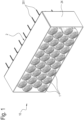
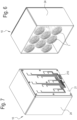
- the numeral 10 denotes a sound reproduction system, comprising a plurality of loudspeaker boxes 1.
- the plurality of loudspeaker boxes 1 may be disposed in a plane or in a line.
- the sound reproduction system 10 also comprises a supporting structure 2 to which the loudspeaker boxes 1 are removably connected.
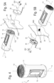
- the loudspeaker box extends between a first end and a second end, the first end and the second end being spaced along a longitudinal axis A. Hence, the loudspeaker box extends between the firs end and the second end along the longitudinal axis.
- the sound transducer 12 is positioned at the first end of the loudspeaker box.
- the cabinet 11 extends around the longitudinal axis A.
- the cabinet 11 surrounds (or encloses or is associated with) a single loudspeaker box 1.
- the cabinet 11 has the shape of a cylinder around the longitudinal axis A; alternatively, the cabinet 11 might have the shape of a parallelepiped (for example, with a square cross section) that is centred on the longitudinal axis A.
- the sound transducer 12 is mounted on the cabinet 11. More specifically, the sound transducer 12 is mounted at a first longitudinal end of the cabinet 11.
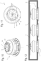
- the first and second conductive tracks 131, 132 are used to carry the signal to the loudspeaker box 1.
- the first conductive track 131 performs the function of positive (or negative) electrode and the second conductive track 132 performs the function of negative (or positive) electrode.
- the first and second conductive tracks 131, 132 also carry the electrical power supply.
- the first and second conductive tracks 131, 132 carry only the signal and there are two further, concentric conductive tracks (for example, surrounding the first and second conductive tracks 131, 132, or surrounded by the first and second conductive tracks 131, 132) to carry the electrical power supply.
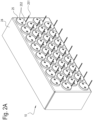
- the supporting structure 2 comprises a frame 24; more specifically, the frame 24 comprises a wall 241.
- the plate 25 is mounted on a first side of the frame 24 (or wall 241), whilst the loudspeaker box 1 is mounted on a second side of the frame 24 (or wall 241), opposite the first side.
- the frame 24 (or the wall 241) is provided with holes 240, 2400.
- the supporting structure 2 comprises a plurality of mechanical connectors 242, which are fixed to the frame 24 (or wall 241).
- Each loudspeaker box 1 is removably mounted on a respective mechanical connector.
- the mechanical connectors 242 are in the form of stud bolts;
- the loudspeaker box 1 has a central hole 14 that is surrounded by the first and the second conductive track 131 and 132;
- the central hole 14 defines a female screw that is removably connected to the stud bolt 242.
- the central hole 14 is aligned with the longitudinal axis A.
- the central hole 14 is located at the second end of the loudspeaker box.
- Each plate 25 also has a plurality of mechanical connectors 252 (for example, screws) to fasten the plate 25 to the frame 24; the frame 24 (or wall 241) has a plurality of holes 2400 in which the mechanical connectors 252 are inserted.
- mechanical connectors 252 for example, screws
- the electrical connectors 3 create a contact between the distribution circuit 23 and the connection circuit 13 whatever the angular position of the loudspeaker box 1 relative to the distribution circuit 23 around the longitudinal axis A and whatever the angular position of the electrical connectors around the longitudinal axis A.
Landscapes
- Physics & Mathematics (AREA)
- Engineering & Computer Science (AREA)
- Acoustics & Sound (AREA)
- Signal Processing (AREA)
- Health & Medical Sciences (AREA)
- Otolaryngology (AREA)
- General Health & Medical Sciences (AREA)
- Details Of Audible-Bandwidth Transducers (AREA)
- Fittings On The Vehicle Exterior For Carrying Loads, And Devices For Holding Or Mounting Articles (AREA)
- Holo Graphy (AREA)
- Toys (AREA)
Claims (15)
- Tonwiedergabesystem (10), umfassend:- eine Tragstruktur (2), einschließend einen Verteilerkreis (23);- eine Lautsprecherbox (1), die mechanisch entfernbar mit der Tragstruktur (2) verbunden ist, wobei sich die Lautsprecherbox entlang einer Längsachse (A) zwischen einem ersten Ende und einem zweiten Ende erstreckt und Folgendes einschließt:ein Gehäuse (11);einen Elektroakustikwandler (12), der mit dem Gehäuse (11) assoziiert und am ersten Ende der Lautsprecherbox positioniert ist;einen Verbindungskreis (13), der am zweiten Ende der Lautsprecherbox positioniert und betriebswirksam elektrisch mit dem Verteilerkreis (23) der Tragstruktur (2) verbunden und ausgelegt ist, um ein Signal vom Verteilerkreis (23) zu empfangen und dieses an den Elektroakustikwandler (12) zu übertragen, wobei der Verbindungskreis (13) der Lautsprecherbox (1) mit dem Verteilerkreis (23) der Tragstruktur (2) an einer Vielzahl von Winkelpositionen, gedreht zueinander um die Längsachse (A), verbindbar ist;- eine Vielzahl von verformbaren elektrischen Steckverbindern (3), wobei der Verbindungskreis (13) der Lautsprecherbox (1) elektrisch mit dem Verteilerkreis (23) der Tragstruktur (2) durch die verformbaren elektrischen Steckverbinder (3) verbunden ist,
wobei mindestens entweder der Verteilerkreis (23) der Tragstruktur (2) und/oder der Verbindungskreis (13) der Lautsprecherbox (1) eine erste Leiterbahn (131) und eine zweite Leiterbahn (132) einschließt/einschließen, die sich senkrecht zur Längsachse (A) erstrecken und entlang jeweiliger konzentrischer ringförmiger Wege rund um die Längsachse (A) verteilt sind;- einen mechanischen Steckverbinder (242), wobei die Lautsprecherbox mechanisch mit der Tragstruktur (2) entfernbar durch den mechanischen Steckverbinder (242) verbunden ist, wobei der mechanische Steckverbinder mit einem Gewinde versehen und fluchtend zur Längsachse (A) angeordnet ist, wobei der mechanische Steckverbinder zudem ein Gewindebolzen ist, der an der Tragstruktur (2) oder der Lautsprecherbox (1) befestigt ist, wodurch der mechanische Steckverbinder (242) innenseitig der ersten Leiterbahn (131) und der zweiten Leiterbahn (132) positioniert ist. - Tonwiedergabesystem (10) nach Anspruch 1, wobei der Elektroakustikwandler (12) und der Verbindungskreis (13) an entgegengesetzten Enden der Lautsprecherbox in Bezug auf die Längsachse (A) befindlich sind.
- Tonwiedergabesystem (10) nach einem der vorhergehenden Ansprüche, wobei der mechanische Steckverbinder (242) einen Gewindebolzen einschließt, der an der Tragstruktur (2) befestigt ist und sich entlang der Längsachse (A) erstreckt, und die Lautsprecherbox (1) eine entfernbare Hohlschraube einschließt, die mit dem Gewindebolzen verbunden ist.
- Tonwiedergabesystem (10) nach einem der vorhergehenden Ansprüche, wobei die erste Leiterbahn (131) und die zweite Leiterbahn (132) im Verbindungskreis (13) der Lautsprecherbox (1) bereitgestellt sind und wobei der Verteilerkreis (23) der Tragstruktur (2) eine zusätzliche erste Leiterbahn (231) und eine zusätzliche zweite Leiterbahn (232) einschließt, die sich senkrecht zur Längsachse (A) erstrecken und entlang jeweiliger konzentrischer ringförmiger Wege rund um die Längsachse (A) verteilt sind, wobei die Vielzahl von verformbaren elektrischen Steckverbindern (3) mindestens einen ersten verformbaren elektrischen Steckverbinder (3) einschließt, der die erste Leiterbahn (131) des Verteilerkreises (13) der Lautsprecherbox (1) mit der zusätzlichen ersten Leiterbahn (231) des Verteilerkreises (23) der Tragstruktur (2) verbindet, und einen zweiten verformbaren elektrischen Steckverbinder (3), der die zweite Leiterbahn (132) des Verbindungskreises (13) der Lautsprecherbox (1) mit der zusätzlichen zweiten Leiterbahn (232) des Verteilerkreises (23) der Tragstruktur (2) verbindet.
- Tonwiedergabesystem (10) nach einem der vorhergehenden Ansprüche, wobei die erste Leiterbahn (131) und die zweite Leiterbahn (132) die Form ununterbrochener konzentrischer Ringe aufweisen, die die Längsachse (A) umgeben.
- Tonwiedergabesystem (10) nach einem der vorhergehenden Ansprüche, wobei das Gehäuse (11) einen Innenraum umschließt, der Druckveränderungen unterliegt, die durch die Schwingung des Elektroakustikwandlers (12) hervorgerufen werden, und wobei die Lautsprecherbox (11) eine oder mehrere passive Resonatoren (15) umfasst, die jeweilige Membrane einschließen, die aufgrund der Druckveränderungen im Innenraum schwingen.
- Tonwiedergabesystem (10) nach einem der vorhergehenden Ansprüche, umfassend eine Vielzahl von Lautsprecherboxen (1), die entfernbar mit der Tragstruktur (2) verbunden sind, wobei die Tragstruktur (2) eine Vielzahl von Verteilerkreisen (23) einschließt und wobei eine jede Lautsprecherbox der Vielzahl von Lautsprecherboxen (1) einen jeweiligen Verbindungskreis (13) einschließt, der elektrisch mit einem jeweiligen Verteilerkreis (23) der Vielzahl von Verteilerkreisen (23) verbunden ist.
- Tonwiedergabesystem (10) nach Anspruch 7, wobei die Lautsprecherbox (1) eine elektronische Leiterplatte (21) einschließt, die ausgelegt ist, um das Signal der Vielzahl von Verteilerkreisen (23) zu übertragen.
- Tonwiedergabesystem (10) nach Anspruch 7 oder 8, wobei die Tragstruktur (2) einen Rahmen (24) einschließt, auf dem die Vielzahl von Lautsprecherboxen (1) montiert ist, wobei ein jeder Verteilerkreis (23) der Vielzahl von Verteilerkreisen (23) eine jeweilige Platte (25) einschließt, die ausgelegt ist, um das Signal zu empfangen und dieses an den Verbindungskreis (13) einer jeden Lautsprecherbox (1) der Vielzahl von Lautsprecherboxen (1) zu übertragen,
wobei der Rahmen (24) zwischen einer jeden Lautsprecherbox (1) der Vielzahl von Lautsprecherboxen (1) und der jeweiligen Platte (25) eingesetzt ist. - Tonwiedergabesystem (10) nach Anspruch 9, umfassend für eine jede Lautsprecherbox (1) der Vielzahl von Lautsprecherboxen (1) eine jeweilige Vielzahl von elektrischen Steckverbindern (3), wobei der Rahmen (24) eine Vielzahl von Löchern (240) definiert, in die die Steckverbinder (3) der Vielzahl von elektrischen Steckverbindern (3) eingefügt wird, um den Verbindungskreis (13) der Lautsprecherbox (1) mit der jeweiligen Platte (25) zu verbinden.
- Tonwiedergabesystem (10) nach einem der vorhergehenden Ansprüche, wobei der Elektroakustikwandler und der Verbindungskreis eine Betriebsstruktur der Lautsprecherbox bilden, wobei die Betriebsstruktur eine Rotationssymmetrie in Bezug auf die Längsachse (A) aufweist.
- Tonwiedergabesystem (10) nach einem der vorhergehenden Ansprüche 1 bis 6, wobei das Gehäuse (11) eine einzelne Lautsprecherbox (1) umgibt und die Form eines Zylinders rund um die Längsachse (A) aufweist.
- Lautsprecherbox (1), die sich entlang einer Längsachse (A) zwischen einem ersten Ende und einem zweiten Ende erstreckt, wobei die Lautsprecherbox (1) entfernbar mit einer Tragstruktur (2) verbindbar ist, einschließend einen Verteilerkreis (23) und Folgendes einschließend:ein Gehäuse (11);einen Elektroakustikwandler (12), der mit dem Gehäuse (11) assoziiert und am ersten Ende der Lautsprecherbox positioniert ist;einen Verbindungskreis (13), der am zweiten Ende der Lautsprecherbox positioniert ist, wobei das zweite Ende gegenständig zum ersten Ende in Bezug auf eine Längsachse (A) angeordnet ist, der Verbindungskreis (13) elektrisch mit dem Verteilerkreis (23) der Tragstruktur (2) verbindbar ist, und der ausgelegt ist, um ein Signal vom Verteilerkreis (23) zu empfangen und dieses an den zweiten Elektroakustikwandler (12) zu übertragen,wobei der Verbindungskreis (13) eine erste Leiterbahn (131) und eine zweite Leiterbahn (132) einschließt, die sich senkrecht zur Längsachse (A) erstrecken und entlang jeweiliger konzentrischer ringförmiger Wege rund um die Längsachse (A) verteilt sind,wobei die Lautsprecherbox mechanisch und entfernbar durch einen mechanischen Steckverbinder mit der Tragstruktur (2), einschließend den Verteilerkreis (23), verbunden ist,wobei der mechanische Steckverbinder mit einem Gewinde versehen und fluchtend zur Längsachse (A) angeordnet ist, wobei der mechanische Steckverbinder zudem ein Gewindebolzen ist, der an der Tragstruktur oder der Lautsprecherbox befestigt ist, wodurch der mechanische Steckverbinder (242) innenseitig der ersten Leiterbahn (131) und der zweiten Leiterbahn (132) positioniert ist, wenn die Lautsprecherbox mit der Tragstruktur (2) verbunden ist;eine Vielzahl von verformbaren elektrischen Steckverbindern (3), um den Verbindungskreis (13) der Lautsprecherbox (1) elektrisch mit dem Verteilerkreis (23) der Tragstruktur (2) zu verbinden.
- Verfahren zum Verbinden einer Lautsprecherbox (1) mit einer Tragstruktur (2), wobei die Tragstruktur (2) einen Verteilerkreis (23) einschließt und die Lautsprecherbox (1) sich entlang einer Längsachse (A) zwischen einem ersten Ende und einem zweiten Ende erstreckt und Folgendes einschließt:ein Gehäuse (11);einen Elektroakustikwandler (12), der mit dem Gehäuse (11) assoziiert und am ersten Ende der Lautsprecherbox positioniert ist;einen Verbindungskreis (13), der am zweiten Ende der Lautsprecherbox positioniert ist,wobei das Verfahren die folgenden Schritte umfasst:- Montieren der Lautsprecherbox (1) an der Tragstruktur (2);- elektrisches Verbinden des Verbindungskreises (13) der Lautsprecherbox (1) mit dem Verteilerkreis der Tragstruktur (2), sodass der Verbindungskreis (13) ein Signal vom Verteilerkreis (23) empfangen und dieses an den Elektroakustikwandler (12) übertragen kann, wobei der Verbindungskreis (13) der Lautsprecherbox (1) mit dem Verteilerkreis (23) der Tragstruktur (2) an einer Vielzahl von Winkelpositionen, gedreht zueinander um die Längsachse (A), verbindbar ist,wobei mindestens entweder der Verteilerkreis (23) der Tragstruktur (2) und/oder der Verbindungskreis (13) der Lautsprecherbox (1) eine erste Leiterbahn (131) und eine zweite Leiterbahn (132) einschließt/einschließen, die sich senkrecht zur Längsachse (A) erstrecken und entlang jeweiliger konzentrischer ringförmiger Wege rund um die Längsachse (A) verteilt sind,wobei die Lautsprecherbox (1) auf der Tragstruktur (2) durch einen mechanischen Steckverbinder (242) montiert ist, wobei der mechanische Steckverbinder mit einem Gewinde versehen und fluchtend zur Längsachse (A) angeordnet ist, wobei der mechanische Steckverbinder zudem ein Gewindebolzen ist, der an der Tragstruktur oder der Lautsprecherbox befestigt ist, wodurch der mechanische Steckverbinder (242) innenseitig der ersten Leiterbahn (131) und der zweiten Leiterbahn (132) positioniert ist,wobei eine Vielzahl von verformbaren elektrischen Steckverbindern (3) bereitgestellt ist, wobei der Verbindungskreis (13) der Lautsprecherbox (1) elektrisch mit dem Verteilerkreis (23) der Tragstruktur (2) durch die verformbaren elektrischen Steckverbinder (3) verbunden ist.
- Verfahren nach Anspruch 14, wobei die Schritte zum Montieren der Lautsprecherbox (1) auf der Tragstruktur (2) und zum elektrischen Verbinden des Verbindungskreises (13) der Lautsprecherbox (1) mit dem Verteilerkreis der Tragstruktur (2) durchgeführt werden, indem die Lautsprecherbox (1) hinführend zur Tragstruktur (2) entlang der Längsachse (A) bewegt wird.
Applications Claiming Priority (1)
| Application Number | Priority Date | Filing Date | Title |
|---|---|---|---|
| IT102021000003173A IT202100003173A1 (it) | 2021-02-12 | 2021-02-12 | Sistema di riproduzione acustica |
Publications (3)
| Publication Number | Publication Date |
|---|---|
| EP4044618A1 EP4044618A1 (de) | 2022-08-17 |
| EP4044618B1 true EP4044618B1 (de) | 2025-04-09 |
| EP4044618C0 EP4044618C0 (de) | 2025-04-09 |
Family
ID=75769745
Family Applications (1)
| Application Number | Title | Priority Date | Filing Date |
|---|---|---|---|
| EP22155354.8A Active EP4044618B1 (de) | 2021-02-12 | 2022-02-07 | Tonwiedergabesystem |
Country Status (4)
| Country | Link |
|---|---|
| US (1) | US12088980B2 (de) |
| EP (1) | EP4044618B1 (de) |
| CN (1) | CN114928777A (de) |
| IT (1) | IT202100003173A1 (de) |
Family Cites Families (21)
| Publication number | Priority date | Publication date | Assignee | Title |
|---|---|---|---|---|
| US3071728A (en) * | 1958-09-02 | 1963-01-01 | Motorola Inc | Portable auto radio receiver |
| US4234766A (en) * | 1979-02-05 | 1980-11-18 | Cacho Gibson C | Speaker assembly |
| US4392548A (en) * | 1980-11-13 | 1983-07-12 | Engineering Development Company | Speaker enclosure and method of producing same |
| US4475226A (en) * | 1983-10-21 | 1984-10-02 | Donald Blechman | Stereo sound and light track system |
| FR2569927B1 (fr) * | 1984-08-29 | 1986-09-19 | Cordier Laurent | Appareil amovible de sonorisation ou/et de visualisation |
| DE3682313D1 (de) * | 1985-04-11 | 1991-12-12 | Telefunken Fernseh & Rundfunk | Lautsprechereinheit. |
| US4757544A (en) * | 1986-12-15 | 1988-07-12 | Steven P. Surgnier | Multi-directional speaker system |
| US4953223A (en) * | 1988-09-08 | 1990-08-28 | Householder George G | Speaker mounting system |
| DE4002672A1 (de) * | 1989-01-31 | 1990-08-02 | Shintom Kk | Mobiles audiosystem |
| US4963854A (en) * | 1989-08-08 | 1990-10-16 | Stuecker Barry M | Light bulb shaped audio signal emitter |
| US5048089A (en) * | 1989-11-27 | 1991-09-10 | Moore Patrick G | Portable, removably attached speaker assembly |
| US5828765A (en) * | 1996-05-03 | 1998-10-27 | Gable; Tony L. | Audio loudspeaker assembly for recessed lighting fixture and audio system using same |
| US6374942B1 (en) | 2000-01-21 | 2002-04-23 | John M. Huggins | System and method for a combined rotatable mechanical and electrical speaker mounting system |
| JP2002158944A (ja) * | 2000-09-07 | 2002-05-31 | Canon Inc | 画像表示システム、画像表示装置及び画像表示装置の周辺機器 |
| US6748096B2 (en) * | 2002-07-03 | 2004-06-08 | Pao-An Chuang | Bulb type speaker structure |
| TW200803573A (en) * | 2006-06-27 | 2008-01-01 | Liu Jen Chi | An expansible sound device |
| KR101681780B1 (ko) * | 2010-08-12 | 2016-12-01 | 엘지전자 주식회사 | 스피커 시스템 |
| US9462361B2 (en) * | 2014-05-19 | 2016-10-04 | Logitech Europe S.A. | Sealed audio speaker design |
| US9913012B2 (en) * | 2014-09-12 | 2018-03-06 | Bose Corporation | Acoustic device with curved passive radiators |
| TWI656301B (zh) * | 2017-03-20 | 2019-04-11 | 仁寶電腦工業股份有限公司 | 電子裝置 |
| CN109922407A (zh) * | 2017-12-13 | 2019-06-21 | 富泰华工业(深圳)有限公司 | 音箱及应用该音箱的电子装置 |
-
2021
- 2021-02-12 IT IT102021000003173A patent/IT202100003173A1/it unknown
-
2022
- 2022-02-07 EP EP22155354.8A patent/EP4044618B1/de active Active
- 2022-02-09 US US17/667,677 patent/US12088980B2/en active Active
- 2022-02-14 CN CN202210135762.7A patent/CN114928777A/zh active Pending
Also Published As
| Publication number | Publication date |
|---|---|
| US20220264206A1 (en) | 2022-08-18 |
| CN114928777A (zh) | 2022-08-19 |
| EP4044618A1 (de) | 2022-08-17 |
| IT202100003173A1 (it) | 2022-08-12 |
| US12088980B2 (en) | 2024-09-10 |
| EP4044618C0 (de) | 2025-04-09 |
Similar Documents
| Publication | Publication Date | Title |
|---|---|---|
| US20240322498A1 (en) | Connector device | |
| JP6657347B2 (ja) | 電池接続モジュール | |
| EP1684544B1 (de) | Montage eines elektroakustischen Wandlers in Schalen von persönlichen Kommunikationsgeräten | |
| US11303993B2 (en) | Sound transducer unit for generating and/or detecting sound waves in the audible wavelength spectrum and/or in the ultrasonic range | |
| KR101962498B1 (ko) | 커넥터 | |
| US20190088918A1 (en) | Battery connection module | |
| US11659319B2 (en) | System for reducing vibrations in loudspeaker | |
| EP4044618B1 (de) | Tonwiedergabesystem | |
| CN1305331A (zh) | 电容式话筒 | |
| EP3264495A1 (de) | Stromabnehmende plattenanordnung und batteriepack damit | |
| WO2021053764A1 (ja) | 光モジュール用パッケージ | |
| EP1969900B1 (de) | Hochtonlautsprecher mit kontinuierlicher rotationsfunktion | |
| RU2718683C2 (ru) | Модульная подвижная система электродинамического громкоговорителя (варианты) | |
| US20080310665A1 (en) | Headphone and headset | |
| CN102860044B (zh) | 音圈扬声器 | |
| CN104038856A (zh) | 扬声器模组 | |
| JPWO2018025378A1 (ja) | 電動駆動装置 | |
| WO2002094460A1 (en) | Connecting apparatus for electro-acoustic devices | |
| CN217849678U (zh) | 麦克风组件及电子设备 | |
| JP4116456B2 (ja) | コネクタ | |
| US12306515B2 (en) | Lens apparatus and image pickup apparatus | |
| EP3145219B1 (de) | Hörgerät | |
| US20080232626A1 (en) | Hearing apparatus with removable volume control module | |
| JP2011087123A (ja) | コンデンサマイクロホン | |
| KR101345367B1 (ko) | 음향변환장치용 진동판 |
Legal Events
| Date | Code | Title | Description |
|---|---|---|---|
| PUAI | Public reference made under article 153(3) epc to a published international application that has entered the european phase |
Free format text: ORIGINAL CODE: 0009012 |
|
| STAA | Information on the status of an ep patent application or granted ep patent |
Free format text: STATUS: THE APPLICATION HAS BEEN PUBLISHED |
|
| AK | Designated contracting states |
Kind code of ref document: A1 Designated state(s): AL AT BE BG CH CY CZ DE DK EE ES FI FR GB GR HR HU IE IS IT LI LT LU LV MC MK MT NL NO PL PT RO RS SE SI SK SM TR |
|
| STAA | Information on the status of an ep patent application or granted ep patent |
Free format text: STATUS: REQUEST FOR EXAMINATION WAS MADE |
|
| 17P | Request for examination filed |
Effective date: 20230217 |
|
| RBV | Designated contracting states (corrected) |
Designated state(s): AL AT BE BG CH CY CZ DE DK EE ES FI FR GB GR HR HU IE IS IT LI LT LU LV MC MK MT NL NO PL PT RO RS SE SI SK SM TR |
|
| GRAP | Despatch of communication of intention to grant a patent |
Free format text: ORIGINAL CODE: EPIDOSNIGR1 |
|
| STAA | Information on the status of an ep patent application or granted ep patent |
Free format text: STATUS: GRANT OF PATENT IS INTENDED |
|
| INTG | Intention to grant announced |
Effective date: 20241008 |
|
| RIN1 | Information on inventor provided before grant (corrected) |
Inventor name: ZUCCHERINI MARTELLO, NICOLO Inventor name: BRACCIOTTI, LEONARDO Inventor name: LASTRUCCI, CLAUDIO |
|
| GRAS | Grant fee paid |
Free format text: ORIGINAL CODE: EPIDOSNIGR3 |
|
| GRAA | (expected) grant |
Free format text: ORIGINAL CODE: 0009210 |
|
| STAA | Information on the status of an ep patent application or granted ep patent |
Free format text: STATUS: THE PATENT HAS BEEN GRANTED |
|
| AK | Designated contracting states |
Kind code of ref document: B1 Designated state(s): AL AT BE BG CH CY CZ DE DK EE ES FI FR GB GR HR HU IE IS IT LI LT LU LV MC MK MT NL NO PL PT RO RS SE SI SK SM TR |
|
| REG | Reference to a national code |
Ref country code: GB Ref legal event code: FG4D |
|
| REG | Reference to a national code |
Ref country code: CH Ref legal event code: EP |
|
| REG | Reference to a national code |
Ref country code: DE Ref legal event code: R096 Ref document number: 602022012744 Country of ref document: DE |
|
| REG | Reference to a national code |
Ref country code: IE Ref legal event code: FG4D |
|
| U01 | Request for unitary effect filed |
Effective date: 20250418 |
|
| U07 | Unitary effect registered |
Designated state(s): AT BE BG DE DK EE FI FR IT LT LU LV MT NL PT RO SE SI Effective date: 20250428 |
|
| PG25 | Lapsed in a contracting state [announced via postgrant information from national office to epo] |
Ref country code: ES Free format text: LAPSE BECAUSE OF FAILURE TO SUBMIT A TRANSLATION OF THE DESCRIPTION OR TO PAY THE FEE WITHIN THE PRESCRIBED TIME-LIMIT Effective date: 20250409 |
|
| PG25 | Lapsed in a contracting state [announced via postgrant information from national office to epo] |
Ref country code: GR Free format text: LAPSE BECAUSE OF FAILURE TO SUBMIT A TRANSLATION OF THE DESCRIPTION OR TO PAY THE FEE WITHIN THE PRESCRIBED TIME-LIMIT Effective date: 20250710 Ref country code: NO Free format text: LAPSE BECAUSE OF FAILURE TO SUBMIT A TRANSLATION OF THE DESCRIPTION OR TO PAY THE FEE WITHIN THE PRESCRIBED TIME-LIMIT Effective date: 20250709 |
|
| PG25 | Lapsed in a contracting state [announced via postgrant information from national office to epo] |
Ref country code: PL Free format text: LAPSE BECAUSE OF FAILURE TO SUBMIT A TRANSLATION OF THE DESCRIPTION OR TO PAY THE FEE WITHIN THE PRESCRIBED TIME-LIMIT Effective date: 20250409 |
|
| PG25 | Lapsed in a contracting state [announced via postgrant information from national office to epo] |
Ref country code: HR Free format text: LAPSE BECAUSE OF FAILURE TO SUBMIT A TRANSLATION OF THE DESCRIPTION OR TO PAY THE FEE WITHIN THE PRESCRIBED TIME-LIMIT Effective date: 20250409 |
|
| PG25 | Lapsed in a contracting state [announced via postgrant information from national office to epo] |
Ref country code: RS Free format text: LAPSE BECAUSE OF FAILURE TO SUBMIT A TRANSLATION OF THE DESCRIPTION OR TO PAY THE FEE WITHIN THE PRESCRIBED TIME-LIMIT Effective date: 20250709 |
|
| PG25 | Lapsed in a contracting state [announced via postgrant information from national office to epo] |
Ref country code: IS Free format text: LAPSE BECAUSE OF FAILURE TO SUBMIT A TRANSLATION OF THE DESCRIPTION OR TO PAY THE FEE WITHIN THE PRESCRIBED TIME-LIMIT Effective date: 20250809 |
|
| PG25 | Lapsed in a contracting state [announced via postgrant information from national office to epo] |
Ref country code: SM Free format text: LAPSE BECAUSE OF FAILURE TO SUBMIT A TRANSLATION OF THE DESCRIPTION OR TO PAY THE FEE WITHIN THE PRESCRIBED TIME-LIMIT Effective date: 20250409 |
|
| PG25 | Lapsed in a contracting state [announced via postgrant information from national office to epo] |
Ref country code: CZ Free format text: LAPSE BECAUSE OF FAILURE TO SUBMIT A TRANSLATION OF THE DESCRIPTION OR TO PAY THE FEE WITHIN THE PRESCRIBED TIME-LIMIT Effective date: 20250409 |
|
| PG25 | Lapsed in a contracting state [announced via postgrant information from national office to epo] |
Ref country code: SK Free format text: LAPSE BECAUSE OF FAILURE TO SUBMIT A TRANSLATION OF THE DESCRIPTION OR TO PAY THE FEE WITHIN THE PRESCRIBED TIME-LIMIT Effective date: 20250409 |
|
| PLBE | No opposition filed within time limit |
Free format text: ORIGINAL CODE: 0009261 |
|
| STAA | Information on the status of an ep patent application or granted ep patent |
Free format text: STATUS: NO OPPOSITION FILED WITHIN TIME LIMIT |