EP3145219B1 - Hörgerät - Google Patents
Hörgerät Download PDFInfo
- Publication number
- EP3145219B1 EP3145219B1 EP16189838.2A EP16189838A EP3145219B1 EP 3145219 B1 EP3145219 B1 EP 3145219B1 EP 16189838 A EP16189838 A EP 16189838A EP 3145219 B1 EP3145219 B1 EP 3145219B1
- Authority
- EP
- European Patent Office
- Prior art keywords
- circuit board
- printed circuit
- chassis
- type
- hearing aid
- Prior art date
- Legal status (The legal status is an assumption and is not a legal conclusion. Google has not performed a legal analysis and makes no representation as to the accuracy of the status listed.)
- Active
Links
- 230000033001 locomotion Effects 0.000 claims description 18
- 210000000613 ear canal Anatomy 0.000 claims description 5
- 230000005236 sound signal Effects 0.000 description 15
- 238000000034 method Methods 0.000 description 8
- 238000012545 processing Methods 0.000 description 5
- 238000004519 manufacturing process Methods 0.000 description 4
- 210000000988 bone and bone Anatomy 0.000 description 3
- 210000005069 ears Anatomy 0.000 description 3
- 230000006870 function Effects 0.000 description 3
- 239000007943 implant Substances 0.000 description 3
- 238000004590 computer program Methods 0.000 description 2
- 230000001419 dependent effect Effects 0.000 description 2
- 230000008569 process Effects 0.000 description 2
- 210000003625 skull Anatomy 0.000 description 2
- 238000003491 array Methods 0.000 description 1
- 210000003926 auditory cortex Anatomy 0.000 description 1
- 230000009286 beneficial effect Effects 0.000 description 1
- 230000008901 benefit Effects 0.000 description 1
- 230000005540 biological transmission Effects 0.000 description 1
- 210000000860 cochlear nerve Anatomy 0.000 description 1
- 238000004891 communication Methods 0.000 description 1
- 230000006835 compression Effects 0.000 description 1
- 238000007906 compression Methods 0.000 description 1
- 238000010276 construction Methods 0.000 description 1
- 238000013461 design Methods 0.000 description 1
- 238000006073 displacement reaction Methods 0.000 description 1
- 210000000883 ear external Anatomy 0.000 description 1
- 210000003027 ear inner Anatomy 0.000 description 1
- 210000000959 ear middle Anatomy 0.000 description 1
- 230000000694 effects Effects 0.000 description 1
- 210000003128 head Anatomy 0.000 description 1
- 238000007373 indentation Methods 0.000 description 1
- 230000014759 maintenance of location Effects 0.000 description 1
- 230000013011 mating Effects 0.000 description 1
- 238000012986 modification Methods 0.000 description 1
- 230000004048 modification Effects 0.000 description 1
- 230000002093 peripheral effect Effects 0.000 description 1
- 230000009467 reduction Effects 0.000 description 1
- 238000012546 transfer Methods 0.000 description 1
Images


Classifications
-
- H—ELECTRICITY
- H04—ELECTRIC COMMUNICATION TECHNIQUE
- H04R—LOUDSPEAKERS, MICROPHONES, GRAMOPHONE PICK-UPS OR LIKE ACOUSTIC ELECTROMECHANICAL TRANSDUCERS; DEAF-AID SETS; PUBLIC ADDRESS SYSTEMS
- H04R25/00—Deaf-aid sets, i.e. electro-acoustic or electro-mechanical hearing aids; Electric tinnitus maskers providing an auditory perception
- H04R25/60—Mounting or interconnection of hearing aid parts, e.g. inside tips, housings or to ossicles
- H04R25/609—Mounting or interconnection of hearing aid parts, e.g. inside tips, housings or to ossicles of circuitry
-
- H—ELECTRICITY
- H04—ELECTRIC COMMUNICATION TECHNIQUE
- H04R—LOUDSPEAKERS, MICROPHONES, GRAMOPHONE PICK-UPS OR LIKE ACOUSTIC ELECTROMECHANICAL TRANSDUCERS; DEAF-AID SETS; PUBLIC ADDRESS SYSTEMS
- H04R25/00—Deaf-aid sets, i.e. electro-acoustic or electro-mechanical hearing aids; Electric tinnitus maskers providing an auditory perception
- H04R25/65—Housing parts, e.g. shells, tips or moulds, or their manufacture
-
- H—ELECTRICITY
- H05—ELECTRIC TECHNIQUES NOT OTHERWISE PROVIDED FOR
- H05K—PRINTED CIRCUITS; CASINGS OR CONSTRUCTIONAL DETAILS OF ELECTRIC APPARATUS; MANUFACTURE OF ASSEMBLAGES OF ELECTRICAL COMPONENTS
- H05K5/00—Casings, cabinets or drawers for electric apparatus
- H05K5/0091—Housing specially adapted for small components
-
- H—ELECTRICITY
- H05—ELECTRIC TECHNIQUES NOT OTHERWISE PROVIDED FOR
- H05K—PRINTED CIRCUITS; CASINGS OR CONSTRUCTIONAL DETAILS OF ELECTRIC APPARATUS; MANUFACTURE OF ASSEMBLAGES OF ELECTRICAL COMPONENTS
- H05K7/00—Constructional details common to different types of electric apparatus
- H05K7/14—Mounting supporting structure in casing or on frame or rack
- H05K7/1401—Mounting supporting structure in casing or on frame or rack comprising clamping or extracting means
- H05K7/1402—Mounting supporting structure in casing or on frame or rack comprising clamping or extracting means for securing or extracting printed circuit boards
- H05K7/1405—Mounting supporting structure in casing or on frame or rack comprising clamping or extracting means for securing or extracting printed circuit boards by clips or resilient members, e.g. hooks
-
- H—ELECTRICITY
- H05—ELECTRIC TECHNIQUES NOT OTHERWISE PROVIDED FOR
- H05K—PRINTED CIRCUITS; CASINGS OR CONSTRUCTIONAL DETAILS OF ELECTRIC APPARATUS; MANUFACTURE OF ASSEMBLAGES OF ELECTRICAL COMPONENTS
- H05K7/00—Constructional details common to different types of electric apparatus
- H05K7/14—Mounting supporting structure in casing or on frame or rack
- H05K7/1422—Printed circuit boards receptacles, e.g. stacked structures, electronic circuit modules or box like frames
- H05K7/1427—Housings
-
- H—ELECTRICITY
- H04—ELECTRIC COMMUNICATION TECHNIQUE
- H04R—LOUDSPEAKERS, MICROPHONES, GRAMOPHONE PICK-UPS OR LIKE ACOUSTIC ELECTROMECHANICAL TRANSDUCERS; DEAF-AID SETS; PUBLIC ADDRESS SYSTEMS
- H04R2225/00—Details of deaf aids covered by H04R25/00, not provided for in any of its subgroups
- H04R2225/021—Behind the ear [BTE] hearing aids
- H04R2225/0213—Constructional details of earhooks, e.g. shape, material
Definitions
- the present disclosure relates to a hearing device having a printed circuit board. More particularly, the disclosure relates to a hearing device equipped with features for holding a printed circuit board in position in the hearing device.
- Modern hearing devices are typically provided with a printed circuit board that needs to be kept in position in order to withstand daily use, handling, drops and furthermore to allow for assembling the hearing device.
- the printed circuit board is typically attached to the hearing device by a holding arrangement in which the printed circuit board is arranged between two parts that are either held together by screws or pressed around the printed circuit board.
- the printed circuit board can be soldered to the parts holding it in position (e.g. battery terminals).
- a volume control module of a hearing apparatus and specifically a hearing device is to be easily replaceable.
- a volume control module including a mounting element, specifically a PCB, and including a volume control mounted on the mounting element, is accordingly provided.
- the mounting element e.g. the PCB, features at least one fixing recess.
- a pin element is inserted in the housing recess and in the fixing recess in a form-fit and removable fashion.
- the vol ume control module can be removed from the housing once the pin element has been removed from the fixing recess. Secure mounting of the volume control module in the housing, but also at the same time rapid replacement of the volume control module, is thereby possible.
- Document US 5,201,008 discloses a modular hearing aid to fit in the user's ear, having a shell, a faceplate fixed to the shell, and an electronic module removably snapped into the faceplate.
- the module includes an open-topped battery compartment which is closed by a lid hinged to the faceplate rather than to the module. This eliminates a bulky hinge on the module and allows a smaller snap fastener between the module and faceplate.
- the hearing device is a hearing device comprising a chassis and a printed circuit board attached to the chassis, wherein the chassis comprises a number of attachment members configured to restrict the motion of the printed circuit board in one or more directions, wherein the attachment members are integrated parts of the chassis.
- the hearing device comprises a chassis and a printed circuit board attached to the chassis.
- the chassis may have any suitable form and size and may preferably be basically symmetrical about a center plane of the chassis.
- the chassis may at least be symmetrical about the center plane where the printed circuit board is to be positioned.
- the chassis comprises a number of attachment members configured to restrict the motion of the printed circuit board in one or more directions. It is preferred that the attachment members are configured to restrict the motion of the printed circuit board in several directions. It is particularly preferred that the attachment members are configured to restrict the motion of the printed circuit board in several independent directions, preferably in three independent directions.
- the attachment members are integrated parts of the chassis, and the attachment members may be shaped as structures protruding from the remaining portion of the chassis.
- the printed circuit board may be a flexible printed circuit board.
- the use of a flexible printed circuit board may be an advantage in hearing devices where many interconnections are required in a compact package.
- the chassis may be a one-piece body.
- the chassis may be assembled from two pieces, where one piece is a sidewall of the chassis.
- the attachment members of the first type may be formed as snap members.
- the snapping here includes that the printed circuit board is to be pressed down so that the printed circuit board snaps into place beneath the first type attachment member.
- the snap members may be integrated parts protruding from the remaining portion of the chassis.
- the snap member may be formed so that the printed circuit board may be inserted from above, and the snap member is formed so as to prevent printed circuit board movement upwards, i.e. the snap member prevent movement in the direction opposite of the direction that the printed circuit board is mounted in, at least during normal use.
- the chassis may comprise a first type of attachment members configured to prevent the printed circuit board to be moved in a direction basically perpendicular to the printed circuit board.
- the printed circuit board can be restricted from being moved in a direction basically perpendicular to the printed circuit board by the first type of attachment members.
- the chassis may comprise two or more of the first type of attachment members.
- the printed circuit board can be firmly fixed to the chassis and be restricted from being moved in a direction basically perpendicular to the printed circuit.
- the chassis may comprise four or more of the first type of attachment members.
- the attachment members can attach the printed circuit board at four or more positions.
- a secure attachment of the printed circuit board to the chassis can be achieved.
- the chassis may, additionally or alternatively, comprise a second type of attachment members configured to prevent the printed circuit board from being moved in directions parallel to the printed circuit board.
- a second type of attachment members configured to prevent the printed circuit board from being moved in directions parallel to the printed circuit board.
- the second type could be a protrusion of a wall element, e.g. a smooth shaped protrusion
- the chassis may comprise one, two or more of the second type of attachment members.
- a reliable and secure attachment of the printed circuit board can be achieved.
- motion or displacement of the printed circuit board may be avoided or at least minimized, e.g. when a hearing aid having such an arrangement is moved during use or e.g. dropped by accident.
- the second type of attachment member may function as a guide for the printed circuit board when being mounted, e.g. the second type attachment member could extend along the height of the receptacle formed in the chassis where the printed circuit board is to be positioned, and one, two or more of the first type of attachment members may be formed lower in the receptacle, so that when assembling the printed circuit board in the chassis, the second type attachment member or members guide the printed circuit board while the printed circuit board travels towards the bottom of the receptacle.
- the printed circuit board may comprise one or more deformable areas or portions configured to be deformed during attachment of the printed circuit board.
- the deformable areas of the printed circuit board enable an easy attachment of the printed circuit board to the chassis.
- the deformable areas of the printed circuit board allow for deformation that makes it possible to arrange the printed circuit board in a position in which it is kept in place by the attachment members of the chassis.
- the chassis may comprise a first wall structure provided along one side of the chassis and a second wall structure extending along the opposite side of the chassis.
- the wall structures define areas in which the attachment members may be provided. Accordingly, the size of the chassis relative to the size of the printed circuit board may be minimised.
- the attachment members may protrude from the first wall structure and extend radially inwardly towards the center plane of the chassis.
- the attachment members can restrict the motion of the printed circuit board in directions basically perpendicular to the printed circuit board.
- a protruding part may extend into a mating opening in a side of the printed circuit board. If several protruding parts are present, a corresponding number of openings in one or more sides of the printed circuit board should be present.
- the openings may be distributed between the sides, so as, e.g. one, two, three or more protrusions are present at each of two opposite (possibly parallel) sides of the printed circuit board. This could e.g.
- the printed circuit board having an oblong geometry, and two protrusions are arranged at two opposite sides of the chassis and two corresponding openings, or indentations, are formed in the two long sides of the printed circuit board, this would prevent movement of the printed circuit board in a direction parallel with the longitudinal axis of the printed circuit board.
- two, three or more protrusions could be present at the two short sides of the printed circuit board.
- the printed circuit board may have a geometry other than square or rectangular. Protrusions could be present are multiple locations along the periphery of the printed circuit board to prevent movement parallel to the surface of the printed circuit board. If the printed circuit board is no flat, movement could be restricted at least in a direction parallel to a side of the printed circuit board.
- the edge of the printed circuit board may be brought into contact with the attachment members during attachment of the printed circuit board.
- the attachment members may protrude from the second wall structure and extend radially inwardly towards the center plane of the chassis. Accordingly, the attachment members are capable of restricting the motion of the printed circuit board in directions basically perpendicular to the printed circuit board.
- the edge of the printed circuit board may be brought into contact with the attachment members during attachment of the printed circuit board.
- the chassis may be dimensioned and shaped to allow the printed circuit board to be provided in a distance from the attachment members so that a gap can be provided between the printed circuit board and the attachment members.
- the printed circuit board may comprise any suitable electronic hardware including microprocessors, microcontrollers, digital signal processors (DSPs), field programmable gate arrays (FPGAs), programmable logic devices (PLDs), gated logic, discrete hardware circuits, and other suitable hardware configured to perform the various functionality described throughout this disclosure.
- Computer program shall be construed broadly to mean instructions, instruction sets, code, code segments, program code, programs, subprograms, software modules, applications, software applications, software packages, routines, subroutines, objects, executables, threads of execution, procedures, functions, etc., whether referred to as software, firmware, middleware, microcode, hardware description language, or otherwise.
- a hearing device may include a hearing aid that is adapted to improve or augment the hearing capability of a user by receiving an acoustic signal from a user's surroundings, generating a corresponding audio signal, possibly modifying the audio signal and providing the possibly modified audio signal as an audible signal to at least one of the user's ears.
- the "hearing device” may further refer to a device such as an earphone or a headset adapted to receive an audio signal electronically, possibly modifying the audio signal and providing the possibly modified audio signal as an audible signal to at least one of the user's ears.
- Such audible signals may be provided in the form of an acoustic signal radiated into the user's outer ear, or an acoustic signal transferred as mechanical vibrations to the user's inner ear through bone structure of the user's head and/or through parts of the middle ear of the user or electric signals transferred directly or indirectly to the cochlear nerve and/or to the auditory cortex of the user.
- the hearing device is adapted to be worn in any known way. This may include i) arranging a unit of the hearing device behind the ear with a tube leading air-borne acoustic signals into the ear canal or with a receiver/ loudspeaker arranged close to or in the ear canal such as in a Behind-the-Ear type hearing aid, and/ or ii) arranging the hearing device entirely or partly in the pinna and/ or in the ear canal of the user such as in a In-the-Ear type hearing aid or In-the-Canal/ Completely-in-Canal type hearing aid, or iii) arranging a unit of the hearing device attached to a fixture implanted into the skull bone such as in Bone Anchored Hearing Aid or Cochlear Implant, or iv) arranging a unit of the hearing device as an entirely or partly implanted unit such as in a Bone Anchored Hearing Aid or a Cochlear Implant.
- a “hearing system” refers to a system comprising one or two hearing devices
- a “binaural hearing system” refers to a system comprising two hearing devices where the devices are adapted to cooperatively provide audible signals to both of the user's ears.
- the hearing system or binaural hearing system may further include an auxiliary device(s) that communicates with at least one hearing device, the auxiliary device affecting the operation of the hearing devices and/or benefitting from the functioning of the hearing devices.
- a wired or wireless communication link between the at least one hearing device and the auxiliary device is established that allows for exchanging information (e.g. control and status signals, possibly audio signals) between the at least one hearing device and the auxiliary device.
- Such auxiliary devices may include at least one of the following: remote controls, remote microphones, audio gateway devices, mobile phones, public-address systems, car audio systems or music players or a combination thereof.
- the audio gateway is adapted to receive a multitude of audio signals such as from an entertainment device like a TV or a music player, a telephone apparatus like a mobile telephone or a computer, a PC.
- the audio gateway is further adapted to select and/or combine an appropriate one of the received audio signals (or combination of signals) for transmission to the at least one hearing device.
- the remote control is adapted to control functionality and operation of the at least one hearing devices.
- the function of the remote control may be implemented in a SmartPhone or in another electronic device, the SmartPhone/ electronic device possibly running an application that controls functionality of the at least one hearing device.
- a hearing device in general, includes i) an input unit such as a microphone for receiving an acoustic signal from a user's surroundings and providing a corresponding input audio signal, and/or ii) a receiving unit for electronically receiving an input audio signal.
- the hearing device further includes a signal processing unit for processing the input audio signal and an output unit for providing an audible signal to the user in dependence on the processed audio signal.
- the input unit may include multiple input microphones, e.g. for providing direction-dependent audio signal processing.
- a directional microphone system is adapted to enhance a target acoustic source among a multitude of acoustic sources in the user's environment.
- the directional system is adapted to detect (such as adaptively detect) from which direction a particular part of the microphone signal originates. This may be achieved by using conventionally known methods.
- the signal processing unit may include an amplifier that is adapted to apply a frequency dependent gain to the input audio signal.
- the signal processing unit may further be adapted to provide other relevant functionality such as compression, noise reduction, etc.
- the output unit may include an output transducer such as a loudspeaker/ receiver for providing an air-borne acoustic signal transcutaneously or percutaneously to the skull bone or a vibrator for providing a structure-borne or liquid-borne acoustic signal.
- the output unit may include one or more output electrodes for providing the electric signals such as in a Cochlear Implant.
- FIG. 1A illustrates a perspective view of a prior art hearing device two-part chassis.
- Fig. 1A illustrates an example of a prior art hearing device chassis having a first member 8 and a second member 10 configured to be screwed, i.e. assembled and held, together by a screw 12.
- the screw 12 is configured to be inserted into a through bore 9 provided in the first member and to be further engagingly received by a threaded bore 9' provided in the second member 10.
- Fig.1B illustrates a prior art hearing device 2 and a printed circuit board 4 being attached to the hearing device 2.
- the hearing device 2 comprises a housing 6 in which a chassis is arranged.
- the chassis comprises first receiving portions 18 and second receiving portions 20.
- the printed circuit board 4 comprises a separate attachment member 14 configured to be inserted into the first receiving portions 18.
- the printed circuit board 4 further comprises an attachment structure 16 configured to be engagely received by the second receiving portions 20.
- Fig. 1C illustrates the prior art hearing device 2 shown in Fig. 1B in a configuration in which the printed circuit board 4 has been attached to the chassis arranged in the housing 6.
- Fig. 2A illustrates a prior art hearing device with a printed circuit board 4 being attached to a chassis 32.
- the deformable structure 30 is provided with holes 28 configured to receive corresponding rod members 26 provided on a structure attached to the printed circuit board 4.
- the chassis 32 moreover comprises two attachment members 24 arranged to be received by corresponding receiving structures 22 provided on the printed circuit board 4.
- Fig. 2B illustrates the prior art hearing device shown in Fig. 2A in a configuration in which the printed circuit board 4 is attached to the chassis 32.
- Fig. 3 illustrates a perspective view of a chassis 32.
- the chassis 32 comprises a first wall structure 48 protruding from the adjacent portion of the chassis 32.
- the chassis 32 further comprises a second wall structure 50 protruding from the adjacent portion of the chassis 32.
- the chassis 32 comprises a longitudinal axis X, a lateral axis Y, and a transversal axis Z.
- the chassis 32 further comprises a center plane C spanned by the longitudinal axis X and the transversal axis Z.
- the chassis 32 is almost symmetrical about the center plane C.
- the chassis 32 comprises a first type of attachment members 34, 34', 36 configured to preventing a printed circuit board to be moved in a direction, basically, perpendicular to the printed circuit board, which is along the Z-axis of the chassis 32.
- first type of attachment members 34, 34', 36 configured to preventing a printed circuit board to be moved in a direction, basically, perpendicular to the printed circuit board, which is along the Z-axis of the chassis 32.
- three of the first type of attachment members are pointed to in the Figure, however, generally, a chassis as disclosed herein for carrying a printed circuit board in a hearing aid may include a number of such first type of attachment members.
- the chassis 32 further comprises a second type of attachment members 38, 38' configured to prevent a printed circuit board to be moved in a direction basically parallel to the printed circuit board, which is along the longitudinal axis X or the lateral axis Y or linear combinations thereof. Accordingly, a firm attachment can be achieved by utilizing the second type of attachment members 38.
- a chassis as disclosed herein for carrying a printed circuit board in a hearing aid may include a different number of such second type of attachment members, and the number of first and second type of attachment members may be chosen in dependence of each other for maximizing retention of the printed circuit board while taking into account the size restrictions and other requirements, such as weight.
- the chassis 32 comprises a plurality of the first type of attachment members 34, 34'. This allows the printed circuit board to be firmly fixed to the chassis 32 and restricts the printed circuit board from being moved in a direction basically perpendicular to the printed circuit board.
- the first type of attachment members 34, 34' allow the printed circuit board to be snapped into place so that the attachment members 34, 34' restrict the upwards motion of the printed circuit board 4, i.e. along the z-axis as illustrated in Fig. 3 .
- first type of attachment members 34, 34' protrude from the first wall structure 48 and extend radially inwardly towards the center plane C of the chassis 32.
- a plurality of a first type of attachment members 36 protrude from the second wall structure 50 and extend radially inwardly towards the center plane C of the chassis 32.
- the combination of utilizing both the first type and the second type attachment members is advantageous in that they keep the printed circuit board in the intended position in the chassis.
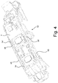
- Fig. 4 illustrates a perspective top view of the chassis 32 shown in Fig. 3.A , a printed circuit board 4 has been attached to the chassis 32 by utilizing the first type of attachment members 34, 34' and the second type of attachment members 38, 38'.
- the printed circuit board 4 is a flexible printed circuit board 4 configured to be deformed in order to attach the printed circuit board 4 to the chassis 32 by utilizing the attachment members 34, 34', 36, 38, 38' protruding from the first wall structure 48 and the second wall structure 50, respectively.
- the second type attachment members 38, 38' are shaped as smooth protrusions extending from the floor of the space where the printed circuit board is to be located and upwards therefrom at a sidewall of the chassis 32.
- Fig. 5 illustrates a top view of a chassis 32 and a printed circuit board 4, wherein the printed circuit board 4 is attached to the chassis 32. It can be seen that a first gap 40 is provided between the printed circuit board 4 and the second type of attachment member 38 at the first wall structure 48. Likewise, a second gap 40' is provided between the printed circuit board 4 and the second type of attachment member 38' at the second wall structure 50.
- the second type of attachment member 38 at the first wall structure 48 and the second type of attachment member 38' at the second wall structure 50 restrict movement of the printed circuit board 4 along the longitudinal axis X and along the lateral axis Y and thus in directions parallel to the printed circuit board 4.
- a first gap 42 is provided between the printed circuit board 4 and the first type of attachment member at the first wall structure 48.
- a second gap 42' is provided between the printed circuit board 4 and the first type of attachment member at the second wall structure 50.
- the first type of attachment members (see Fig. 6 ) at the first wall structure 48 and at the second wall structure 50 restrict movement of the printed circuit board 4 in directions perpendicular to the printed circuit board 4.
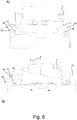
- Fig. 6A illustrates a side view of a chassis 32 and a printed circuit board 4.
- the printed circuit board 4 is being attached to the chassis 32 by being moved in the direction indicated by the arrows 44.
- the chassis 32 comprises a first wall structure 48 and an attachment member 34 protruding therefrom.
- the chassis 32 comprises a second wall structure 50 and an attachment member 36 protruding therefrom.
- Fig. 6B illustrates a side view of the chassis 32 and the printed circuit board 4 shown in Fig. 6A .
- the printed circuit board 4 has been attached to the chassis 32 and thus the printed circuit board 4 is fixed to the chassis 32.
- the printed circuit board 4 is restricted from being moved along the transversal axis Z of the chassis 32.
- the printed circuit board 4 comprises a first deformable portion 46 and a second deformable portion 46' provided at the peripheral portions of the printed circuit board 4.
- the deformable portions 46, 46' make it easier to attach the printed circuit board 4 to the chassis 32 and to "pass" the attachment members 34, 36.
- the deformable portions are elastically deformable meaning that they obtain a geometry substantially identical to their original geometry after the deformation process.
Claims (13)
- Hörhilfsgerät (2) mit einem Gehäuse, das dazu konfiguriert ist, hinter dem Ohr eines Benutzers angeordnet zu sein, mit einem Rohr, das über die Luft übertragene akustische Signale in den Gehörgang leitet, oder mit einem Empfänger/Lautsprecher, der nahe oder in dem Gehörgang angeordnet ist, das Hörhilfsgerät umfassend einen Rahmen (32) und eine Leiterplatte (4), die an dem Rahmen (32) befestigt ist, wobei der Rahmen (32) eine erste Wandstruktur (48), die entlang einer Seite des Rahmens (32) bereitgestellt ist, und eine zweite Wandstruktur (50), die entlang einer gegenüberliegenden Seite des Rahmens (32) verläuft, umfasst, wobei der Rahmen (32) eine Längsachse (X), eine Seitenachse (Y) und eine Querachse (Z) umfasst, wobei die Leiterplatte zwischen der ersten Wandstruktur und der zweiten Wandstruktur aufzunehmen ist, wobei der Rahmen (32) in dem Gehäuse angeordnet ist, wobei der Rahmen (32) ein Befestigungselement einer ersten Art (34, 34', 36), das dazu konfiguriert ist, die Bewegung der Leiterplatte (4) in einer ersten Richtung (Z) entlang der Querachse (Z) zu beschränken, und ein Befestigungselement einer zweiten Art (38, 38'), das dazu konfiguriert ist, die Bewegung der Leiterplatte (4) in einer zweiten Richtung (X, Y, Z), die sich von der ersten Richtung unterscheidet, zu beschränken, wobei die zweite Richtung entlang der Längsachse (X) und/oder der Seitenachse (Y) verläuft, umfasst, wobei die Befestigungselemente der ersten und der zweiten Art (34, 34', 36, 38, 38') integrierte Teile des Rahmens (32) sind.
- Hörhilfsgerät (2) nach Anspruch 1, wobei die Befestigungselemente der ersten Art (34, 34', 36) als Schnappelemente (34, 34', 36, 38, 38') gebildet sind.
- Hörhilfsgerät (2) nach Anspruch 1 oder 2, wobei die erste Art von Befestigungselementen (34, 34', 36) dazu konfiguriert ist, zu verhindern, dass die Leiterplatte (4) in einer Richtung im Wesentlichen senkrecht zu der Leiterplatte (4) bewegt wird.
- Hörhilfsgerät (2) nach Anspruch 3, wobei der Rahmen (32) zwei, drei, vier oder mehr der ersten Art von Befestigungselementen (34, 34', 36) umfasst.
- Hörhilfsgerät (2) nach einem der Ansprüche 1-4, wobei die zweite Art von Befestigungselementen (38) dazu konfiguriert ist, zu verhindern, dass die Leiterplatte (4) in einer Richtung parallel zu der Leiterplatte (4) bewegt wird.
- Hörhilfsgerät (2) nach Anspruch 5, wobei der Rahmen (32) zwei, drei, vier oder mehr der zweiten Art von Befestigungselementen (38, 38') umfasst.
- Hörhilfsgerät (2) nach einem der Ansprüche 1-6, wobei die Leiterplatte (4) einen oder mehrere verformbare Bereiche (46, 46') umfasst, die dazu konfiguriert sind, während der Befestigung der Leiterplatte (4) verformt zu werden.
- Hörhilfsgerät (2) nach Anspruch 1, wobei ein Befestigungselement der ersten Art (34, 34') aus der ersten Wandstruktur (48) hervorsteht und radial nach innen in Richtung der Mittelebene (C) des Rahmens (32) verläuft und/oder wobei ein Befestigungselement der ersten Art (36) aus der zweiten Wandstruktur (50) hervorsteht und radial nach innen in Richtung der Mittelebene (C) des Rahmens (32) verläuft.
- Hörhilfsgerät (2) nach Anspruch 1 oder 8, wobei ein Befestigungselement der zweiten Art (36) aus der zweiten Wandstruktur (50) hervorsteht und radial nach innen in Richtung der Mittelebene (C) des Rahmens (32) verläuft und/oder wobei ein Befestigungselement der zweiten Art (34, 34') aus der ersten Wandstruktur (48) hervorsteht und radial nach innen in Richtung der Mittelebene (C) des Rahmens (32) verläuft.
- Hörhilfsgerät (2) nach Anspruch 9, wobei die erste und/oder die zweite Wandstruktur zusammen mit einem Bodenwandteil einen Teil eines Hohlraums bildet, in dem die Leiterplatte gehalten wird, und das Befestigungselement der zweiten Art (38, 38') entlang des ersten und/oder des zweiten Wandteils von dem Bodenwandteil über den Punkt, an dem die Leiterplatte gehalten wird, hinaus verläuft.
- Hörhilfsgerät (2) nach Anspruch 10, wobei der Punkt, an dem die Leiterplatte gehalten wird, durch ein Befestigungselement der ersten Art definiert ist.
- Hörhilfsgerät (2) nach einem der Ansprüche 1-11, wobei der Rahmen (32) so bemessen und geformt ist, um es der Leiterplatte (4) zu ermöglichen, in einem Abstand von den Befestigungselementen (34, 34', 36, 38, 38') bereitgestellt zu sein, sodass eine Lücke (40) zwischen der Leiterplatte (4) und den Befestigungselementen (34, 34', 36, 38, 38') bereitgestellt werden kann.
- Hörhilfsgerät (2) nach einem der Ansprüche 1-10, wobei der Rahmen (32) ein einstückiger Körper oder ein Mehrfachkomponentenkörper ist.
Applications Claiming Priority (1)
| Application Number | Priority Date | Filing Date | Title |
|---|---|---|---|
| EP15185992 | 2015-09-21 |
Publications (2)
| Publication Number | Publication Date |
|---|---|
| EP3145219A1 EP3145219A1 (de) | 2017-03-22 |
| EP3145219B1 true EP3145219B1 (de) | 2021-06-16 |
Family
ID=54151183
Family Applications (1)
| Application Number | Title | Priority Date | Filing Date |
|---|---|---|---|
| EP16189838.2A Active EP3145219B1 (de) | 2015-09-21 | 2016-09-21 | Hörgerät |
Country Status (4)
| Country | Link |
|---|---|
| US (1) | US10165377B2 (de) |
| EP (1) | EP3145219B1 (de) |
| CN (1) | CN106878896B (de) |
| DK (1) | DK3145219T3 (de) |
Families Citing this family (1)
| Publication number | Priority date | Publication date | Assignee | Title |
|---|---|---|---|---|
| EP3310077A1 (de) * | 2016-10-13 | 2018-04-18 | Oticon A/s | Hörgerät und verfahren zum schutz der komponenten eines hörgeräts |
Citations (6)
| Publication number | Priority date | Publication date | Assignee | Title |
|---|---|---|---|---|
| US4890329A (en) | 1987-06-26 | 1989-12-26 | Siemens Aktiengesellschaft | Hearing aid comprising printed circuit board |
| US20010043709A1 (en) | 2000-05-17 | 2001-11-22 | Frank Panitzsch | Hearing aid fitted with a rechargeable battery, and application of such a rechargeable battery |
| US6733319B1 (en) | 1999-04-23 | 2004-05-11 | Microtronic A/S | Connector and method for establishing solderfree connections between a rigid main PCB and associated conductors |
| US20060185969A1 (en) | 2005-02-15 | 2006-08-24 | Ehrenfried Erbe | Hearing aid with a control element |
| US20070019834A1 (en) | 2004-03-31 | 2007-01-25 | Widex A/S | Component for a hearing aid and a hearing aid |
| WO2010107389A1 (en) | 2009-03-18 | 2010-09-23 | Siemens Medical Instruments Pte Ltd | Base for hearing aid circuitry |
Family Cites Families (34)
| Publication number | Priority date | Publication date | Assignee | Title |
|---|---|---|---|---|
| NL270384A (de) * | 1960-10-24 | |||
| US3475566A (en) * | 1966-01-04 | 1969-10-28 | Sonotone Corp | Battery holder and switch for hearing aid unit |
| DE7918029U1 (de) * | 1979-06-22 | 1980-12-04 | Siemens Ag, 1000 Berlin Und 8000 Muenchen | Kleinhoergeraet |
| DE8234198U1 (de) * | 1982-12-06 | 1986-03-13 | Siemens AG, 1000 Berlin und 8000 München | Kleinhörgerät |
| DE8428516U1 (de) * | 1984-09-27 | 1986-01-23 | Siemens AG, 1000 Berlin und 8000 München | Hinter dem Ohr zu tragendes Hörgerät |
| US5201008A (en) * | 1987-01-27 | 1993-04-06 | Unitron Industries Ltd. | Modular hearing aid with lid hinged to faceplate |
| DE8708894U1 (de) | 1987-06-26 | 1988-10-27 | Siemens Ag, 1000 Berlin Und 8000 Muenchen, De | |
| DE8713088U1 (de) * | 1987-09-29 | 1989-01-26 | Siemens Ag, 1000 Berlin Und 8000 Muenchen, De | |
| US4917504A (en) * | 1989-05-05 | 1990-04-17 | Plantronics, Inc. | Communications headset |
| CA2014960C (en) * | 1990-04-19 | 1995-07-25 | Horst Arndt | Modular hearing aid |
| DE59009156D1 (de) * | 1990-12-18 | 1995-06-29 | Siemens Ag | Hörgerät. |
| JP3044966B2 (ja) * | 1993-04-09 | 2000-05-22 | 松下電器産業株式会社 | 基板の下受装置 |
| DE4343702C1 (de) * | 1993-12-21 | 1995-03-09 | Siemens Audiologische Technik | Am Kopf tragbares Hörgerät |
| US6041128A (en) * | 1994-01-31 | 2000-03-21 | Rion Kabushiki Kaisha | Battery receiving chamber and hearing aid |
| US5967837A (en) | 1996-10-01 | 1999-10-19 | Alps Automotive, Inc. | Assembly for connecting an electric/electronic device to a printed circuit board |
| ATE554607T1 (de) * | 1998-10-07 | 2012-05-15 | Oticon As | Hörgerät |
| WO2000021334A2 (en) * | 1998-10-07 | 2000-04-13 | Oticon A/S | Behind-the-ear hearing aid |
| AU5969099A (en) * | 1998-10-07 | 2000-04-26 | Oticon A/S | A hearing aid |
| WO1999043194A2 (de) * | 1999-06-16 | 1999-09-02 | Phonak Ag | Hinterohr-hörgerät |
| JP2001128278A (ja) * | 1999-10-26 | 2001-05-11 | Matsushita Electric Ind Co Ltd | イヤホンジャック保持装置 |
| US6748094B1 (en) * | 2000-03-03 | 2004-06-08 | Advanced Bionics Corporation | Connector system for BTE hearing devices |
| CN2475182Y (zh) * | 2001-05-08 | 2002-01-30 | 庆良电子股份有限公司 | 连接器挡板 |
| JP2003229682A (ja) * | 2002-02-06 | 2003-08-15 | Keihin Corp | 電子回路基板の固定部材 |
| US7844065B2 (en) * | 2005-01-14 | 2010-11-30 | Phonak Ag | Hearing instrument |
| US7742613B2 (en) * | 2006-06-21 | 2010-06-22 | Phonak Ag | Connecting means for housings of hearing devices |
| DE102007013419B3 (de) | 2007-03-20 | 2008-07-10 | Siemens Audiologische Technik Gmbh | Hörvorrichtung mit entnehmbarem Lautstärkestellermodul |
| JP6144865B2 (ja) | 2007-12-27 | 2017-06-07 | ジーエヌ リザウンド エー/エスGn Resound A/S | プリント回路基板で形成された壁を有する聴覚補助装置 |
| US8542857B2 (en) | 2008-03-31 | 2013-09-24 | Cochlear Limited | Bone conduction device with a movement sensor |
| CN201374428Y (zh) * | 2009-02-27 | 2009-12-30 | 富港电子(东莞)有限公司 | 柔性电路板连接器 |
| CN201659530U (zh) * | 2009-11-19 | 2010-12-01 | 名硕电脑(苏州)有限公司 | 固定装置 |
| CN102445973A (zh) * | 2010-10-13 | 2012-05-09 | 英业达股份有限公司 | 电路板固定机构 |
| CN201827780U (zh) * | 2010-10-22 | 2011-05-11 | 北京京东方光电科技有限公司 | 背光模组及液晶显示器 |
| CN102695392B (zh) * | 2012-04-27 | 2015-03-25 | 台达电子工业股份有限公司 | 用于汽车转向系统的防水控制器 |
| CN203233623U (zh) * | 2013-04-24 | 2013-10-09 | 广东美的制冷设备有限公司 | 一种pcb板的安装固定结构 |
-
2016
- 2016-09-21 CN CN201610840485.4A patent/CN106878896B/zh active Active
- 2016-09-21 DK DK16189838.2T patent/DK3145219T3/da active
- 2016-09-21 EP EP16189838.2A patent/EP3145219B1/de active Active
- 2016-09-21 US US15/271,996 patent/US10165377B2/en active Active
Patent Citations (6)
| Publication number | Priority date | Publication date | Assignee | Title |
|---|---|---|---|---|
| US4890329A (en) | 1987-06-26 | 1989-12-26 | Siemens Aktiengesellschaft | Hearing aid comprising printed circuit board |
| US6733319B1 (en) | 1999-04-23 | 2004-05-11 | Microtronic A/S | Connector and method for establishing solderfree connections between a rigid main PCB and associated conductors |
| US20010043709A1 (en) | 2000-05-17 | 2001-11-22 | Frank Panitzsch | Hearing aid fitted with a rechargeable battery, and application of such a rechargeable battery |
| US20070019834A1 (en) | 2004-03-31 | 2007-01-25 | Widex A/S | Component for a hearing aid and a hearing aid |
| US20060185969A1 (en) | 2005-02-15 | 2006-08-24 | Ehrenfried Erbe | Hearing aid with a control element |
| WO2010107389A1 (en) | 2009-03-18 | 2010-09-23 | Siemens Medical Instruments Pte Ltd | Base for hearing aid circuitry |
Also Published As
| Publication number | Publication date |
|---|---|
| EP3145219A1 (de) | 2017-03-22 |
| CN106878896A (zh) | 2017-06-20 |
| US20170086001A1 (en) | 2017-03-23 |
| CN106878896B (zh) | 2021-03-02 |
| DK3145219T3 (da) | 2021-07-26 |
| US10165377B2 (en) | 2018-12-25 |
Similar Documents
| Publication | Publication Date | Title |
|---|---|---|
| US10555096B2 (en) | Antenna unit | |
| CN108933984B (zh) | 沿单一曲轴的助听器装置 | |
| US11683650B2 (en) | Antenna configuration for a hearing aid system | |
| US10412513B2 (en) | Hearing device | |
| EP3145219B1 (de) | Hörgerät | |
| EP3136754A1 (de) | Hörgerät | |
| US11849285B2 (en) | Hearing aid device | |
| EP3435688A1 (de) | Im ohr tragbares hörgerät mit unverdeckten elektronischen bauteilen | |
| EP3128578B1 (de) | Batterieanordnung für ein hörgerät | |
| US11778395B2 (en) | Hearing aid battery connected to ear shell | |
| EP4120697A1 (de) | Hörvorrichtung, die zumindest teilweise hinter dem ohr eines benutzers getragen wird | |
| US20230209238A1 (en) | Charger device for hearing devices | |
| EP3886129A1 (de) | Druckknopf für schalter | |
| US11785398B2 (en) | Hearing aid with transmission power adaptation | |
| EP3462750A1 (de) | Fixierelement für eine telespule in einem hörgerät |
Legal Events
| Date | Code | Title | Description |
|---|---|---|---|
| PUAI | Public reference made under article 153(3) epc to a published international application that has entered the european phase |
Free format text: ORIGINAL CODE: 0009012 |
|
| STAA | Information on the status of an ep patent application or granted ep patent |
Free format text: STATUS: THE APPLICATION HAS BEEN PUBLISHED |
|
| AK | Designated contracting states |
Kind code of ref document: A1 Designated state(s): AL AT BE BG CH CY CZ DE DK EE ES FI FR GB GR HR HU IE IS IT LI LT LU LV MC MK MT NL NO PL PT RO RS SE SI SK SM TR |
|
| AX | Request for extension of the european patent |
Extension state: BA ME |
|
| STAA | Information on the status of an ep patent application or granted ep patent |
Free format text: STATUS: REQUEST FOR EXAMINATION WAS MADE |
|
| 17P | Request for examination filed |
Effective date: 20170922 |
|
| RBV | Designated contracting states (corrected) |
Designated state(s): AL AT BE BG CH CY CZ DE DK EE ES FI FR GB GR HR HU IE IS IT LI LT LU LV MC MK MT NL NO PL PT RO RS SE SI SK SM TR |
|
| STAA | Information on the status of an ep patent application or granted ep patent |
Free format text: STATUS: EXAMINATION IS IN PROGRESS |
|
| 17Q | First examination report despatched |
Effective date: 20180320 |
|
| GRAP | Despatch of communication of intention to grant a patent |
Free format text: ORIGINAL CODE: EPIDOSNIGR1 |
|
| STAA | Information on the status of an ep patent application or granted ep patent |
Free format text: STATUS: GRANT OF PATENT IS INTENDED |
|
| INTG | Intention to grant announced |
Effective date: 20210112 |
|
| GRAS | Grant fee paid |
Free format text: ORIGINAL CODE: EPIDOSNIGR3 |
|
| GRAA | (expected) grant |
Free format text: ORIGINAL CODE: 0009210 |
|
| STAA | Information on the status of an ep patent application or granted ep patent |
Free format text: STATUS: THE PATENT HAS BEEN GRANTED |
|
| AK | Designated contracting states |
Kind code of ref document: B1 Designated state(s): AL AT BE BG CH CY CZ DE DK EE ES FI FR GB GR HR HU IE IS IT LI LT LU LV MC MK MT NL NO PL PT RO RS SE SI SK SM TR |
|
| REG | Reference to a national code |
Ref country code: GB Ref legal event code: FG4D |
|
| REG | Reference to a national code |
Ref country code: CH Ref legal event code: EP |
|
| REG | Reference to a national code |
Ref country code: DE Ref legal event code: R096 Ref document number: 602016059310 Country of ref document: DE |
|
| REG | Reference to a national code |
Ref country code: AT Ref legal event code: REF Ref document number: 1403334 Country of ref document: AT Kind code of ref document: T Effective date: 20210715 |
|
| REG | Reference to a national code |
Ref country code: IE Ref legal event code: FG4D |
|
| REG | Reference to a national code |
Ref country code: DK Ref legal event code: T3 Effective date: 20210722 |
|
| REG | Reference to a national code |
Ref country code: LT Ref legal event code: MG9D |
|
| PG25 | Lapsed in a contracting state [announced via postgrant information from national office to epo] |
Ref country code: HR Free format text: LAPSE BECAUSE OF FAILURE TO SUBMIT A TRANSLATION OF THE DESCRIPTION OR TO PAY THE FEE WITHIN THE PRESCRIBED TIME-LIMIT Effective date: 20210616 Ref country code: BG Free format text: LAPSE BECAUSE OF FAILURE TO SUBMIT A TRANSLATION OF THE DESCRIPTION OR TO PAY THE FEE WITHIN THE PRESCRIBED TIME-LIMIT Effective date: 20210916 Ref country code: FI Free format text: LAPSE BECAUSE OF FAILURE TO SUBMIT A TRANSLATION OF THE DESCRIPTION OR TO PAY THE FEE WITHIN THE PRESCRIBED TIME-LIMIT Effective date: 20210616 Ref country code: LT Free format text: LAPSE BECAUSE OF FAILURE TO SUBMIT A TRANSLATION OF THE DESCRIPTION OR TO PAY THE FEE WITHIN THE PRESCRIBED TIME-LIMIT Effective date: 20210616 |
|
| REG | Reference to a national code |
Ref country code: AT Ref legal event code: MK05 Ref document number: 1403334 Country of ref document: AT Kind code of ref document: T Effective date: 20210616 |
|
| REG | Reference to a national code |
Ref country code: NL Ref legal event code: MP Effective date: 20210616 |
|
| PG25 | Lapsed in a contracting state [announced via postgrant information from national office to epo] |
Ref country code: NO Free format text: LAPSE BECAUSE OF FAILURE TO SUBMIT A TRANSLATION OF THE DESCRIPTION OR TO PAY THE FEE WITHIN THE PRESCRIBED TIME-LIMIT Effective date: 20210916 Ref country code: RS Free format text: LAPSE BECAUSE OF FAILURE TO SUBMIT A TRANSLATION OF THE DESCRIPTION OR TO PAY THE FEE WITHIN THE PRESCRIBED TIME-LIMIT Effective date: 20210616 Ref country code: SE Free format text: LAPSE BECAUSE OF FAILURE TO SUBMIT A TRANSLATION OF THE DESCRIPTION OR TO PAY THE FEE WITHIN THE PRESCRIBED TIME-LIMIT Effective date: 20210616 Ref country code: LV Free format text: LAPSE BECAUSE OF FAILURE TO SUBMIT A TRANSLATION OF THE DESCRIPTION OR TO PAY THE FEE WITHIN THE PRESCRIBED TIME-LIMIT Effective date: 20210616 Ref country code: GR Free format text: LAPSE BECAUSE OF FAILURE TO SUBMIT A TRANSLATION OF THE DESCRIPTION OR TO PAY THE FEE WITHIN THE PRESCRIBED TIME-LIMIT Effective date: 20210917 |
|
| PG25 | Lapsed in a contracting state [announced via postgrant information from national office to epo] |
Ref country code: CZ Free format text: LAPSE BECAUSE OF FAILURE TO SUBMIT A TRANSLATION OF THE DESCRIPTION OR TO PAY THE FEE WITHIN THE PRESCRIBED TIME-LIMIT Effective date: 20210616 Ref country code: EE Free format text: LAPSE BECAUSE OF FAILURE TO SUBMIT A TRANSLATION OF THE DESCRIPTION OR TO PAY THE FEE WITHIN THE PRESCRIBED TIME-LIMIT Effective date: 20210616 Ref country code: SK Free format text: LAPSE BECAUSE OF FAILURE TO SUBMIT A TRANSLATION OF THE DESCRIPTION OR TO PAY THE FEE WITHIN THE PRESCRIBED TIME-LIMIT Effective date: 20210616 Ref country code: SM Free format text: LAPSE BECAUSE OF FAILURE TO SUBMIT A TRANSLATION OF THE DESCRIPTION OR TO PAY THE FEE WITHIN THE PRESCRIBED TIME-LIMIT Effective date: 20210616 Ref country code: PT Free format text: LAPSE BECAUSE OF FAILURE TO SUBMIT A TRANSLATION OF THE DESCRIPTION OR TO PAY THE FEE WITHIN THE PRESCRIBED TIME-LIMIT Effective date: 20211018 Ref country code: RO Free format text: LAPSE BECAUSE OF FAILURE TO SUBMIT A TRANSLATION OF THE DESCRIPTION OR TO PAY THE FEE WITHIN THE PRESCRIBED TIME-LIMIT Effective date: 20210616 Ref country code: NL Free format text: LAPSE BECAUSE OF FAILURE TO SUBMIT A TRANSLATION OF THE DESCRIPTION OR TO PAY THE FEE WITHIN THE PRESCRIBED TIME-LIMIT Effective date: 20210616 Ref country code: ES Free format text: LAPSE BECAUSE OF FAILURE TO SUBMIT A TRANSLATION OF THE DESCRIPTION OR TO PAY THE FEE WITHIN THE PRESCRIBED TIME-LIMIT Effective date: 20210616 Ref country code: AT Free format text: LAPSE BECAUSE OF FAILURE TO SUBMIT A TRANSLATION OF THE DESCRIPTION OR TO PAY THE FEE WITHIN THE PRESCRIBED TIME-LIMIT Effective date: 20210616 |
|
| PG25 | Lapsed in a contracting state [announced via postgrant information from national office to epo] |
Ref country code: PL Free format text: LAPSE BECAUSE OF FAILURE TO SUBMIT A TRANSLATION OF THE DESCRIPTION OR TO PAY THE FEE WITHIN THE PRESCRIBED TIME-LIMIT Effective date: 20210616 |
|
| REG | Reference to a national code |
Ref country code: DE Ref legal event code: R026 Ref document number: 602016059310 Country of ref document: DE |
|
| PLBI | Opposition filed |
Free format text: ORIGINAL CODE: 0009260 |
|
| PLAX | Notice of opposition and request to file observation + time limit sent |
Free format text: ORIGINAL CODE: EPIDOSNOBS2 |
|
| 26 | Opposition filed |
Opponent name: GN HEARING A/S Effective date: 20220316 |
|
| REG | Reference to a national code |
Ref country code: BE Ref legal event code: MM Effective date: 20210930 |
|
| PG25 | Lapsed in a contracting state [announced via postgrant information from national office to epo] |
Ref country code: MC Free format text: LAPSE BECAUSE OF FAILURE TO SUBMIT A TRANSLATION OF THE DESCRIPTION OR TO PAY THE FEE WITHIN THE PRESCRIBED TIME-LIMIT Effective date: 20210616 Ref country code: AL Free format text: LAPSE BECAUSE OF FAILURE TO SUBMIT A TRANSLATION OF THE DESCRIPTION OR TO PAY THE FEE WITHIN THE PRESCRIBED TIME-LIMIT Effective date: 20210616 |
|
| PG25 | Lapsed in a contracting state [announced via postgrant information from national office to epo] |
Ref country code: LU Free format text: LAPSE BECAUSE OF NON-PAYMENT OF DUE FEES Effective date: 20210921 Ref country code: IT Free format text: LAPSE BECAUSE OF FAILURE TO SUBMIT A TRANSLATION OF THE DESCRIPTION OR TO PAY THE FEE WITHIN THE PRESCRIBED TIME-LIMIT Effective date: 20210616 Ref country code: IE Free format text: LAPSE BECAUSE OF NON-PAYMENT OF DUE FEES Effective date: 20210921 Ref country code: BE Free format text: LAPSE BECAUSE OF NON-PAYMENT OF DUE FEES Effective date: 20210930 |
|
| PLBB | Reply of patent proprietor to notice(s) of opposition received |
Free format text: ORIGINAL CODE: EPIDOSNOBS3 |
|
| RDAF | Communication despatched that patent is revoked |
Free format text: ORIGINAL CODE: EPIDOSNREV1 |
|
| PG25 | Lapsed in a contracting state [announced via postgrant information from national office to epo] |
Ref country code: HU Free format text: LAPSE BECAUSE OF FAILURE TO SUBMIT A TRANSLATION OF THE DESCRIPTION OR TO PAY THE FEE WITHIN THE PRESCRIBED TIME-LIMIT; INVALID AB INITIO Effective date: 20160921 |
|
| PG25 | Lapsed in a contracting state [announced via postgrant information from national office to epo] |
Ref country code: CY Free format text: LAPSE BECAUSE OF FAILURE TO SUBMIT A TRANSLATION OF THE DESCRIPTION OR TO PAY THE FEE WITHIN THE PRESCRIBED TIME-LIMIT Effective date: 20210616 |
|
| APAH | Appeal reference modified |
Free format text: ORIGINAL CODE: EPIDOSCREFNO |
|
| APBM | Appeal reference recorded |
Free format text: ORIGINAL CODE: EPIDOSNREFNO |
|
| APBP | Date of receipt of notice of appeal recorded |
Free format text: ORIGINAL CODE: EPIDOSNNOA2O |
|
| APBQ | Date of receipt of statement of grounds of appeal recorded |
Free format text: ORIGINAL CODE: EPIDOSNNOA3O |
|
| PGFP | Annual fee paid to national office [announced via postgrant information from national office to epo] |
Ref country code: GB Payment date: 20230831 Year of fee payment: 8 |
|
| PGFP | Annual fee paid to national office [announced via postgrant information from national office to epo] |
Ref country code: FR Payment date: 20230831 Year of fee payment: 8 Ref country code: DK Payment date: 20230831 Year of fee payment: 8 Ref country code: DE Payment date: 20230905 Year of fee payment: 8 |
|
| APAH | Appeal reference modified |
Free format text: ORIGINAL CODE: EPIDOSCREFNO |
|
| PGFP | Annual fee paid to national office [announced via postgrant information from national office to epo] |
Ref country code: CH Payment date: 20231001 Year of fee payment: 8 |
|
| PG25 | Lapsed in a contracting state [announced via postgrant information from national office to epo] |
Ref country code: MK Free format text: LAPSE BECAUSE OF FAILURE TO SUBMIT A TRANSLATION OF THE DESCRIPTION OR TO PAY THE FEE WITHIN THE PRESCRIBED TIME-LIMIT Effective date: 20210616 |