EP4044618A1 - Tonwiedergabesystem - Google Patents
Tonwiedergabesystem Download PDFInfo
- Publication number
- EP4044618A1 EP4044618A1 EP22155354.8A EP22155354A EP4044618A1 EP 4044618 A1 EP4044618 A1 EP 4044618A1 EP 22155354 A EP22155354 A EP 22155354A EP 4044618 A1 EP4044618 A1 EP 4044618A1
- Authority
- EP
- European Patent Office
- Prior art keywords
- loudspeaker box
- supporting structure
- conductive track
- longitudinal axis
- circuit
- Prior art date
- Legal status (The legal status is an assumption and is not a legal conclusion. Google has not performed a legal analysis and makes no representation as to the accuracy of the status listed.)
- Granted
Links
Images


Classifications
-
- H—ELECTRICITY
- H04—ELECTRIC COMMUNICATION TECHNIQUE
- H04R—LOUDSPEAKERS, MICROPHONES, GRAMOPHONE PICK-UPS OR LIKE ACOUSTIC ELECTROMECHANICAL TRANSDUCERS; DEAF-AID SETS; PUBLIC ADDRESS SYSTEMS
- H04R1/00—Details of transducers, loudspeakers or microphones
- H04R1/02—Casings; Cabinets ; Supports therefor; Mountings therein
- H04R1/025—Arrangements for fixing loudspeaker transducers, e.g. in a box, furniture
-
- H—ELECTRICITY
- H04—ELECTRIC COMMUNICATION TECHNIQUE
- H04R—LOUDSPEAKERS, MICROPHONES, GRAMOPHONE PICK-UPS OR LIKE ACOUSTIC ELECTROMECHANICAL TRANSDUCERS; DEAF-AID SETS; PUBLIC ADDRESS SYSTEMS
- H04R1/00—Details of transducers, loudspeakers or microphones
- H04R1/02—Casings; Cabinets ; Supports therefor; Mountings therein
- H04R1/026—Supports for loudspeaker casings
-
- H—ELECTRICITY
- H04—ELECTRIC COMMUNICATION TECHNIQUE
- H04R—LOUDSPEAKERS, MICROPHONES, GRAMOPHONE PICK-UPS OR LIKE ACOUSTIC ELECTROMECHANICAL TRANSDUCERS; DEAF-AID SETS; PUBLIC ADDRESS SYSTEMS
- H04R1/00—Details of transducers, loudspeakers or microphones
- H04R1/20—Arrangements for obtaining desired frequency or directional characteristics
- H04R1/22—Arrangements for obtaining desired frequency or directional characteristics for obtaining desired frequency characteristic only
- H04R1/28—Transducer mountings or enclosures modified by provision of mechanical or acoustic impedances, e.g. resonator, damping means
- H04R1/2807—Enclosures comprising vibrating or resonating arrangements
- H04R1/283—Enclosures comprising vibrating or resonating arrangements using a passive diaphragm
- H04R1/2834—Enclosures comprising vibrating or resonating arrangements using a passive diaphragm for loudspeaker transducers
-
- H—ELECTRICITY
- H04—ELECTRIC COMMUNICATION TECHNIQUE
- H04R—LOUDSPEAKERS, MICROPHONES, GRAMOPHONE PICK-UPS OR LIKE ACOUSTIC ELECTROMECHANICAL TRANSDUCERS; DEAF-AID SETS; PUBLIC ADDRESS SYSTEMS
- H04R1/00—Details of transducers, loudspeakers or microphones
- H04R1/20—Arrangements for obtaining desired frequency or directional characteristics
- H04R1/32—Arrangements for obtaining desired frequency or directional characteristics for obtaining desired directional characteristic only
- H04R1/323—Arrangements for obtaining desired frequency or directional characteristics for obtaining desired directional characteristic only for loudspeakers
-
- H—ELECTRICITY
- H04—ELECTRIC COMMUNICATION TECHNIQUE
- H04R—LOUDSPEAKERS, MICROPHONES, GRAMOPHONE PICK-UPS OR LIKE ACOUSTIC ELECTROMECHANICAL TRANSDUCERS; DEAF-AID SETS; PUBLIC ADDRESS SYSTEMS
- H04R3/00—Circuits for transducers, loudspeakers or microphones
- H04R3/12—Circuits for transducers, loudspeakers or microphones for distributing signals to two or more loudspeakers
-
- H—ELECTRICITY
- H04—ELECTRIC COMMUNICATION TECHNIQUE
- H04R—LOUDSPEAKERS, MICROPHONES, GRAMOPHONE PICK-UPS OR LIKE ACOUSTIC ELECTROMECHANICAL TRANSDUCERS; DEAF-AID SETS; PUBLIC ADDRESS SYSTEMS
- H04R1/00—Details of transducers, loudspeakers or microphones
- H04R1/20—Arrangements for obtaining desired frequency or directional characteristics
- H04R1/22—Arrangements for obtaining desired frequency or directional characteristics for obtaining desired frequency characteristic only
- H04R1/28—Transducer mountings or enclosures modified by provision of mechanical or acoustic impedances, e.g. resonator, damping means
- H04R1/2807—Enclosures comprising vibrating or resonating arrangements
-
- H—ELECTRICITY
- H04—ELECTRIC COMMUNICATION TECHNIQUE
- H04R—LOUDSPEAKERS, MICROPHONES, GRAMOPHONE PICK-UPS OR LIKE ACOUSTIC ELECTROMECHANICAL TRANSDUCERS; DEAF-AID SETS; PUBLIC ADDRESS SYSTEMS
- H04R2201/00—Details of transducers, loudspeakers or microphones covered by H04R1/00 but not provided for in any of its subgroups
- H04R2201/02—Details casings, cabinets or mounting therein for transducers covered by H04R1/02 but not provided for in any of its subgroups
- H04R2201/025—Transducer mountings or cabinet supports enabling variable orientation of transducer of cabinet
-
- H—ELECTRICITY
- H04—ELECTRIC COMMUNICATION TECHNIQUE
- H04R—LOUDSPEAKERS, MICROPHONES, GRAMOPHONE PICK-UPS OR LIKE ACOUSTIC ELECTROMECHANICAL TRANSDUCERS; DEAF-AID SETS; PUBLIC ADDRESS SYSTEMS
- H04R2201/00—Details of transducers, loudspeakers or microphones covered by H04R1/00 but not provided for in any of its subgroups
- H04R2201/40—Details of arrangements for obtaining desired directional characteristic by combining a number of identical transducers covered by H04R1/40 but not provided for in any of its subgroups
- H04R2201/401—2D or 3D arrays of transducers
-
- H—ELECTRICITY
- H04—ELECTRIC COMMUNICATION TECHNIQUE
- H04R—LOUDSPEAKERS, MICROPHONES, GRAMOPHONE PICK-UPS OR LIKE ACOUSTIC ELECTROMECHANICAL TRANSDUCERS; DEAF-AID SETS; PUBLIC ADDRESS SYSTEMS
- H04R2420/00—Details of connection covered by H04R, not provided for in its groups
- H04R2420/09—Applications of special connectors, e.g. USB, XLR, in loudspeakers, microphones or headphones
Definitions
- the present invention relates to a sound reproduction system, a loudspeaker box and a method for connecting a loudspeaker box to a supporting structure.
- the field of the invention is that of sound reproduction systems and, more specifically, loudspeaker boxes.
- patent document US6374942B1 discloses a system for mechanically and electrically connecting a loudspeaker box to a supporting structure where the loudspeaker box and the supporting structure are electrically coupled to each other in such a way as to allow full rotation of the loudspeaker box in relation to the supporting structure.
- the system comprises a first shell that is fixed to the supporting structure and a second shell that is fixed to the loudspeaker box, the two shells being configured to be interconnected; the shells make the structure considerably complex and occupy a relatively large amount of space.
- the electrical connection is made by connectors that are not very reliable and have a tendency to be disconnected.
- loudspeakers are provided in patent documents US2008/123894A1 and US4757544A . These loudspeakers may be adjusted in their position once they are connected to another loudspeaker. However, these documents do not fulfil the need for an improved system for mechanically and electrically connecting a loudspeaker box to a supporting structure where the loudspeaker box and the supporting structure.
- the aim of this disclosure is to provide a sound reproduction system, a loudspeaker box (i.e. a loudspeaker) and a method for connecting a loudspeaker box to a supporting structure to overcome at least one of the above mentioned disadvantages of the prior art.
- a loudspeaker box i.e. a loudspeaker
- a method for connecting a loudspeaker box to a supporting structure to overcome at least one of the above mentioned disadvantages of the prior art.
- the sound reproduction system comprises a supporting structure.
- the supporting structure is a stationary, fixed structure.
- the supporting structure includes a supporting wall, developing in a supporting plane.
- the supporting structure includes a distribution circuit.
- the distribution circuit develops in the supporting plane.
- the sound reproduction system comprises a loudspeaker box, or at least one loudspeaker box.
- the loudspeaker box is removably connected to the supporting structure. More specifically, the loudspeaker box is mechanically and electrically connected to the supporting structure in such a way that it can be removed.
- the loudspeaker box includes a sound transducer, associated with the cabinet.
- the sound transducer may comprise a vibrating membrane (alternatively, it might include a piezoelectric material or other systems of essentially known type in the field of sound reproduction systems).
- the sound transducer includes an electric motor configured to set the membrane vibrating.
- the loudspeaker box includes a cabinet.
- the cabinet is configured to enclose an air space around the sound transducer. This air space is functional to sound performance.
- the cabinet is (or is associated with) the loudspeaker box.
- the cabinet extends around a longitudinal axis.
- the cabinet is associated with a plurality of loudspeaker boxes.
- the loudspeaker box is mechanically connected to the supporting structure. More specifically, in an embodiment, the cabinet is mechanically connected to the supporting structure, or is mounted on the supporting structure.
- the loudspeaker box includes a connection circuit, which is operatively electrically connected to the distribution circuit of the supporting structure and is configured to receive a signal from the distribution circuit and to transmit it to the sound transducer (or to the motor) to make the vibrating membrane vibrate.
- the connection circuit is also configured to receive an electrical power supply from the distribution circuit of the supporting structure and to transmit it to the sound transducer (or to the motor).
- the sound transducer and the connection circuit are positioned at opposite ends of the self-same loudspeaker box, with respect to a longitudinal axis.
- the sound transducer and the connection circuit form an operating structure of the loudspeaker box.
- the operating structure of the loudspeaker box has a rotational symmetry with respect to the longitudinal axis.
- the present disclosure provides two embodiments.
- the (each) loudspeaker box is provided with a dedicated (respective) cabinet; in this case, the cabinet is preferably part of the operating structure of the loudspeaker box, which exhibits a rotational symmetry with respect to the longitudinal axis.
- a plurality of loudspeaker boxes shares one same cabinet; in this case, the cabinet does not form part of the operating structure of the loudspeaker box which exhibits the rotational symmetry with respect to the longitudinal axis.
- connection circuit of the loudspeaker box is connectable (that is, it is configured for being operatively connected) to the distribution circuit of the supporting structure at a plurality of angular positions, rotated in relation to each other around the longitudinal axis.
- connection circuit of the loudspeaker box and the distribution circuit of the supporting structure are configured to maintain electrical continuity during a rotation (preferably complete) of the loudspeaker box relative to the supporting structure about the longitudinal axis.
- complete rotation is meant a rotation through 360°, hence through an infinite plurality of angular positions.
- the loudspeaker box can be rotated around the longitudinal axis among a plurality of angular positions, while the sound transducer and the connection circuit (thus the operating structure) of the loudspeaker box remain oriented along the longitudinal axis.
- the cabinet rotates as one with the loudspeaker box; instead, in the embodiment where the cabinet is common to a plurality of loudspeaker boxes, the cabinet remains stationary during the rotation of the loudspeaker box.
- At least one between the distribution circuit of the supporting structure and the connection circuit of the loudspeaker box includes a first conductive track and a second conductive track, which extend perpendicularly to the longitudinal axis and are distributed along respective concentric annular paths around the longitudinal axis. More specifically, the second conductive track extends around the longitudinal axis internally relative to the first conductive track.
- first and second conductive tracks running all the way around the longitudinal axis and oriented in a plane perpendicular to the longitudinal axis (or in two or more planes perpendicular to the longitudinal axis) makes the electrical connection independent of the relative angular position of the loudspeaker box in relation to the supporting structure and is, at the same time, a practical, simple and reliable system.
- the loudspeaker box may be movable relative to the supporting structure between a connected configuration and a disconnected configuration.
- the loudspeaker box In the disconnected configuration, the loudspeaker box may be positioned at a plurality of angular positions which are rotated angularly relative to each other about the longitudinal axis and where there is electrical continuity.
- connection circuit may include the first and the second conductive track and the distribution circuit may include connectors which are operatively connected to the first and the second conductive track.
- distribution circuit may include the first and the second conductive track and the connection circuit may include connectors which are operatively connected to the first and the second conductive track.
- both the distribution circuit and the connection circuit may include a respective first conductive track and a respective second conductive track
- the loudspeaker box may include connectors which are interconnected between the conductive tracks of the distribution circuit and the conductive tracks of the connection circuit; more specifically, in this embodiment, at least a first connector (or a first pair of connectors) that is interconnected between the first conductive track of the distribution circuit and the first conductive track of the connection circuit and a second connector (or a second pair of connectors) that is interconnected between the second conductive track of the distribution circuit and the second conductive track of the connection circuit.
- the sound reproduction system comprises a mechanical connector, where the cabinet is mechanically connected to the supporting structure removably by the mechanical connector.
- the mechanical connector is positioned internally in relation to the first conductive track and the second conductive track.
- the mechanical connector is aligned with the longitudinal axis.
- the mechanical connector is threaded.
- the loudspeaker box (more specifically, the operating structure of the loudspeaker box) can be mechanically coupled to the supporting structure by rotating the loudspeaker box (more specifically, the operating structure of the loudspeaker box) about the longitudinal axis. In this way, the same rotating movement of the (the operating structure of the) loudspeaker box allows both mechanical and electrical connection of the loudspeaker box to the supporting structure.
- the final angular position of the loudspeaker box with respect to the supporting structure may depend on the respective threads and on the screwing force applied and thus may not known a priori, but this does not affect the correct electrical connection between the loudspeaker box to the supporting structure and does not change the orientation of the loudspeaker box (because the sound transducer is always oriented in the longitudinal axis).
- the mechanical connector is a stud bolt fastened to the supporting structure and extending along the longitudinal axis, and the loudspeaker box includes a removable female screw connected to the stud bolt.
- the mechanical connector is a stud bolt fastened to the loudspeaker box and the supporting structure includes a removable female screw connected to the stud bolt.
- the mechanical connector might include an adhesive material that joins the cabinet to the supporting structure.
- the adhesive material might be positioned internally and/or externally in relation to the first and the second conductive track.
- the sound reproduction system comprises a plurality of electrical connectors; the connection circuit of the loudspeaker box is electrically connected to the distribution circuit of the supporting structure through the electrical connectors.
- the electrical connectors are deformable electrical connectors (for example, sliding contact connectors that is a slip ring connectors).
- the first and the second conductive track are provided in the connection circuit of the loudspeaker box and the distribution circuit includes a further first conductive track and a further second conductive track, which extend perpendicularly to the longitudinal axis and are distributed along respective concentric annular tracks around the longitudinal axis.
- the plurality of deformable electrical connectors includes at least a first deformable electrical connector (or a first pair of deformable electrical connectors) that connects the first conductive track of the connection circuit to the further first conductive track of the distribution circuit, and a second deformable electrical connector (or a second pair of deformable electrical connectors) that connects the second conductive track of the loudspeaker box to the further second conductive track of the distribution circuit of the supporting structure.
- the first conductive track and the second conductive track are shaped like uninterrupted concentric rings surrounding the longitudinal axis.
- the connection circuit and the distribution circuit are shaped in such a way as to maintain electrical continuity during a complete rotation of the loudspeaker box relative to the supporting structure about the longitudinal axis.
- first and/or the second conductive track although they extend along annular tracks around the longitudinal axis, may have breaks in them; in this case, there are nevertheless a plurality of relative angular positions of the loudspeaker box in relation to the supporting structure, where electrical connection is made, but these angular positions are not infinite, that is to say, they do not cover a 360° rotation.
- the cabinet encloses an internal space which is subject to pressure variations caused by vibration of the sound transducer.
- the loudspeaker box is self-consistent: it can work even if it is not integrated in the sound reproduction system.
- the loudspeaker box comprises one or more passive resonators, including respective membranes that are made to vibrate by the pressure variations of the internal space.
- passive resonators including respective membranes that are made to vibrate by the pressure variations of the internal space.
- the sound reproduction system comprises a plurality of loudspeaker boxes which are removably connected to the supporting structure.
- Each loudspeaker box of the plurality of loudspeaker boxes has one or more of the features described herein in connection with the loudspeaker box.
- the supporting structure includes a plurality of distribution circuits. More specifically, each loudspeaker box of the plurality of loudspeaker boxes includes a respective connection circuit that is electrically connected to a respective distribution circuit of the plurality of distribution circuits.
- the sound reproduction system according to this disclosure has the advantage of allowing a loudspeaker box to be replaced quickly and easily in the event of a fault, without having to also remove the other loudspeaker boxes of the sound reproduction system. Moreover, the electrical connection is particularly reliable.
- the loudspeaker box includes an electronic printed circuit configured to carry the signal to the plurality of distribution circuits.
- the supporting structure includes a frame.
- the loudspeaker box, or the plurality of loudspeaker boxes, is mounted on the frame.
- the distribution circuit, or each distribution circuit of the plurality of distribution circuits, includes a plate; the plate is configured to receive the signal and to transmit it to the connection circuit of a respective loudspeaker box.
- the frame is interposed between the loudspeaker box, or each loudspeaker box of the plurality of loudspeaker boxes, and the respective plate. Both the plate and the loudspeaker box are mechanically supported by the frame.
- the sound reproduction system comprises, for the loudspeaker box, or for each loudspeaker box of the plurality of loudspeaker boxes, a respective plurality of electrical connectors; the frame defines a plurality of holes in which the electrical connectors of the plurality of electrical connectors are inserted in order to connect the connection circuit of the loudspeaker box to the respective plate.
- the electrical connectors are preferably rigid, that is to say, not deformable.
- This disclosure also provides a loudspeaker box; the loudspeaker box is connectable to the supporting structure and is made according to one or more aspects of this disclosure.
- the loudspeaker box is configured to be installed in a sound reproduction system according to one or more aspects of this disclosure.
- This disclosure also provides a method for connecting a loudspeaker box to a supporting structure.
- the supporting structure includes a distribution circuit.
- the loudspeaker box includes: a cabinet which extends around a longitudinal axis; a sound transducer, associated with the cabinet and comprising a vibrating membrane; a connection circuit.
- the method comprises a step of mounting (that is, mechanically connecting) the loudspeaker box to the supporting structure. More specifically, in an embodiment, the cabinet is removably connected to the supporting structure.
- the method comprises a step of electrically connecting the connection circuit of the loudspeaker box to the distribution circuit of the supporting structure in such a way that the connection circuit can receive a signal from the distribution circuit and transmit it to the sound transducer to cause the vibrating membrane to vibrate.
- the connection circuit of the loudspeaker box is connectable to the distribution circuit of the supporting structure at a plurality of different angular positions, rotated in relation to each other around the longitudinal axis.
- At least one between the distribution circuit of the supporting structure and the connection circuit of the loudspeaker box includes a first conductive track and a second conductive track, which extend perpendicularly to the longitudinal axis and are distributed along respective concentric annular paths around the longitudinal axis.
- the steps of mounting the cabinet on the supporting structure and electrically connecting the connection circuit of the loudspeaker box to the distribution circuit of the supporting structure are carried out through a movement of the loudspeaker box towards the supporting structure along the longitudinal axis. More specifically, the steps of mounting the cabinet on the supporting structure and electrically connecting the connection circuit of the loudspeaker box to the distribution circuit of the supporting structure may be carried out simultaneously through said movement of the loudspeaker box towards the supporting structure. In an embodiment, the steps of mounting the cabinet on the supporting structure and electrically connecting the connection circuit of the loudspeaker box also include rotating the loudspeaker box relative to the supporting structure.
- the method for connecting the loudspeaker box to the supporting structure is repeated for each loudspeaker box of the plurality of loudspeaker boxes making up the system.
- the supporting structure includes a plurality of distribution circuits and each loudspeaker box is connected to a respective distribution circuit of the plurality.
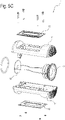
- the numeral 1 denotes a loudspeaker box (i.e. a loudspeaker).
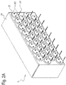
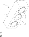
- the numeral 10 denotes a sound reproduction system, comprising a plurality of loudspeaker boxes 1.
- the plurality of loudspeaker boxes 1 may be disposed in a plane or in a line.
- the sound reproduction system 10 also comprises a supporting structure 2 to which the loudspeaker boxes 1 are removably connected.
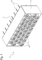
- the loudspeaker box 1 comprises a cabinet 11 which is functional to sound performance.
- Each loudspeaker box 1 includes a sound transducer 12 that includes a vibrating membrane.
- the loudspeaker box extends between a first end and a second end, the first end and the second end being spaced along a longitudinal axis A. Hence, the loudspeaker box extends between the firs end and the second end along the longitudinal axis.
- the sound transducer 12 is positioned at the first end of the loudspeaker box.
- the cabinet 11 extends around the longitudinal axis A.
- the cabinet 11 surrounds (or encloses or is associated with) a single loudspeaker box 1.
- the cabinet 11 has the shape of a cylinder around the longitudinal axis A; alternatively, the cabinet 11 might have the shape of a parallelepiped (for example, with a square cross section) that is centred on the longitudinal axis A.
- the sound transducer 12 is mounted on the cabinet 11. More specifically, the sound transducer 12 is mounted at a first longitudinal end of the cabinet 11.
- the cabinet 11 surrounds (or encloses or is associated with) a row or a matrix of loudspeaker boxes 1.
- the loudspeaker box 1 includes at least one passive resonator 15 (more specifically, a pair of passive resonators 15) including respective vibrating membranes mounted on the cabinet 11.
- the at least one passive resonator 15 is mounted along a side wall of the cabinet, between the first longitudinal end and a second longitudinal end, opposite the first along the longitudinal axis A.
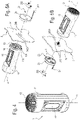
- the loudspeaker box 1 includes a connection circuit 13 configured to receive a signal and to transmit it to the sound transducer 12.
- the connection circuit 13 may be connected to the cabinet 11.
- the connection circuit 13 is positioned at the second end of the loudspeaker box. Hence, the sound transducer 12 and the connection circuit 13 are located at opposite ends of the loudspeaker box, with respect to the longitudinal axis A.
- the connection circuit 13 comprises a first conductive track 131 and a second conductive track 132.
- the first conductive track 131 and the second conductive track 132 are planar and extend in a plane perpendicular to the longitudinal axis A.
- the first conductive track 131 and the second conductive track 132 are ring-shaped (that is, they have the shape of circular crowns) surrounding the longitudinal axis A.
- the second conductive track 132 surrounds the first conductive track 131.
- the first and second conductive tracks 131, 132 are used to carry the signal to the loudspeaker box 1.
- the first conductive track 131 performs the function of positive (or negative) electrode and the second conductive track 132 performs the function of negative (or positive) electrode.
- the first and second conductive tracks 131, 132 also carry the electrical power supply.
- the first and second conductive tracks 131, 132 carry only the signal and there are two further, concentric conductive tracks (for example, surrounding the first and second conductive tracks 131, 132, or surrounded by the first and second conductive tracks 131, 132) to carry the electrical power supply.
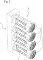
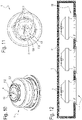
- the supporting structure 2 For each loudspeaker box 1, the supporting structure 2 comprises a distribution circuit 23.
- the distribution circuit 23 is configured to transmit the signal (and preferably also the electrical power supply) to the connection circuit 13 of the respective loudspeaker box 1.
- the sound reproduction system 10 also comprises electrical connectors 3, configured for electrically connecting the connection circuit 13 of the loudspeaker box 1 to the distribution circuit 23 of the supporting structure 2.
- the supporting structure 2 comprises a frame 24; more specifically, the frame 24 comprises a wall 241.
- each distribution circuit 23 includes a plate 25.
- the plate 25 comprises connector terminals 251 in the form of electrical cables, which carry the signal to the plate 25.
- the plate 25 is mounted on a first side of the frame 24 (or wall 241), whilst the loudspeaker box 1 is mounted on a second side of the frame 24 (or wall 241), opposite the first side.
- the frame 24 (or the wall 241) is provided with holes 240, 2400.
- the electrical connectors 3 are fixed to the plate 25, pass through the holes 240 and come into contact with the connection circuit 13 of the loudspeaker box 1. More specifically, at least a first connector 3 (positive electrode), which comes into contact with the first conductive track 131, and a second connector 3 (negative electrode), which comes into contact with the second conductive track 132, are provided. Thus, the first connector 3, which comes into contact with the first conductive track 131, is closer to the longitudinal axis A than the second connector, which comes into contact with the second conductive track 132.
- the electrical connectors 3 make contact whatever the angular position of the loudspeaker box 1 relative to the plate 25 around the longitudinal axis A.
- the supporting structure 2 comprises a plurality of mechanical connectors 242, which are fixed to the frame 24 (or wall 241).
- Each loudspeaker box 1 is removably mounted on a respective mechanical connector.
- the mechanical connectors 242 are in the form of stud bolts;
- the loudspeaker box 1 has a central hole 14 that is surrounded by the first and the second conductive track 131 and 132;
- the central hole 14 defines a female screw that is removably connected to the stud bolt 242.
- the central hole 14 is aligned with the longitudinal axis A.
- the central hole 14 is located at the second end of the loudspeaker box.
- Each plate 25 also has a plurality of mechanical connectors 252 (for example, screws) to fasten the plate 25 to the frame 24; the frame 24 (or wall 241) has a plurality of holes 2400 in which the mechanical connectors 252 are inserted.
- mechanical connectors 252 for example, screws
- the supporting structure 2 comprises a printed distribution circuit 21 associated with the frame 24.
- the printed circuit 21 may in turn include electronic, amplifying, processing and control circuitry and the printed circuit 21 itself defines the distribution circuits 23 for the loudspeaker boxes 1.
- the electrical connectors 3 are fixed to the printed circuit 21 and connect the printed circuit 21 to the connection circuit 13.
- the printed circuit 21 substantially performs the function of the plates 25 and of the connector terminals 251.
- the supporting structure 2 also includes a common interface connector 210, configured to carry the signal to the printed circuit 21.
- each plate 25, hence each loudspeaker box 1 has its own respective connector terminals 251; in the embodiment with the printed circuit 21, on the other hand, there is a single terminal for powering the entire printed circuit 21, hence all the loudspeaker boxes 1 of the sound reproduction system 10.
- the distribution circuit 23 comprises a first conductive track 231 and a second conductive track 232.
- the second conductive track 232 and the first conductive track 231 extend along paths that surround the longitudinal axis A. More specifically, the second conductive track 232 surrounds the first conductive track 231.
- the first conductive track 231 of the distribution circuit 23 has the shape of a ring (or circular crown) of the same size as the first conductive track 131 of the connection circuit 13.
- the second conductive track 232 of the distribution circuit 23 has the shape of a ring (or circular crown) of the same size as the second conductive track 132 of the connection circuit 13.
- At least one flexible electrical connector 3 (or preferably a pair of flexible electrical connectors 3) is fixed to the first conductive track 231 to connect the first conductive track 231 of the distribution circuit 23 to the first conductive track 131 of the connection circuit 13.
- at least one flexible electrical connector 3 (or preferably a pair of flexible electrical connectors 3) is fixed to the second conductive track 232 to connect the second conductive track 232 of the distribution circuit 23 to the second conductive track 132 of the connection circuit 13.
- the electrical connectors 3 create a contact between the distribution circuit 23 and the connection circuit 13 whatever the angular position of the loudspeaker box 1 relative to the distribution circuit 23 around the longitudinal axis A and whatever the angular position of the electrical connectors around the longitudinal axis A.
- the conductive tracks 131 and 132 of the connection circuit 13 and the conductive tracks 231 and 232 of the distribution circuit 23 have the shape of unbroken rings surrounding the longitudinal axis A
- the ring shapes of each of them surrounding the longitudinal axis A might, in another embodiment, not illustrated, include portions that are spaced apart. In this case, electrical contact between the connection circuit 13 of the loudspeaker box 1 and the distribution circuit 23 is made only at some of the relative angular positions.
Landscapes
- Physics & Mathematics (AREA)
- Engineering & Computer Science (AREA)
- Acoustics & Sound (AREA)
- Signal Processing (AREA)
- Health & Medical Sciences (AREA)
- Otolaryngology (AREA)
- General Health & Medical Sciences (AREA)
- Details Of Audible-Bandwidth Transducers (AREA)
- Fittings On The Vehicle Exterior For Carrying Loads, And Devices For Holding Or Mounting Articles (AREA)
- Holo Graphy (AREA)
- Toys (AREA)
Applications Claiming Priority (1)
| Application Number | Priority Date | Filing Date | Title |
|---|---|---|---|
| IT102021000003173A IT202100003173A1 (it) | 2021-02-12 | 2021-02-12 | Sistema di riproduzione acustica |
Publications (3)
| Publication Number | Publication Date |
|---|---|
| EP4044618A1 true EP4044618A1 (de) | 2022-08-17 |
| EP4044618B1 EP4044618B1 (de) | 2025-04-09 |
| EP4044618C0 EP4044618C0 (de) | 2025-04-09 |
Family
ID=75769745
Family Applications (1)
| Application Number | Title | Priority Date | Filing Date |
|---|---|---|---|
| EP22155354.8A Active EP4044618B1 (de) | 2021-02-12 | 2022-02-07 | Tonwiedergabesystem |
Country Status (4)
| Country | Link |
|---|---|
| US (1) | US12088980B2 (de) |
| EP (1) | EP4044618B1 (de) |
| CN (1) | CN114928777A (de) |
| IT (1) | IT202100003173A1 (de) |
Citations (4)
| Publication number | Priority date | Publication date | Assignee | Title |
|---|---|---|---|---|
| US4757544A (en) | 1986-12-15 | 1988-07-12 | Steven P. Surgnier | Multi-directional speaker system |
| US6374942B1 (en) | 2000-01-21 | 2002-04-23 | John M. Huggins | System and method for a combined rotatable mechanical and electrical speaker mounting system |
| US20080123894A1 (en) | 2006-06-27 | 2008-05-29 | Chen-Chi Lu | Expandable speaker apparatus |
| US20120039476A1 (en) * | 2010-08-12 | 2012-02-16 | Lg Electronics Inc. | Speaker |
Family Cites Families (17)
| Publication number | Priority date | Publication date | Assignee | Title |
|---|---|---|---|---|
| US3071728A (en) * | 1958-09-02 | 1963-01-01 | Motorola Inc | Portable auto radio receiver |
| US4234766A (en) * | 1979-02-05 | 1980-11-18 | Cacho Gibson C | Speaker assembly |
| US4392548A (en) * | 1980-11-13 | 1983-07-12 | Engineering Development Company | Speaker enclosure and method of producing same |
| US4475226A (en) * | 1983-10-21 | 1984-10-02 | Donald Blechman | Stereo sound and light track system |
| FR2569927B1 (fr) * | 1984-08-29 | 1986-09-19 | Cordier Laurent | Appareil amovible de sonorisation ou/et de visualisation |
| DE3682313D1 (de) * | 1985-04-11 | 1991-12-12 | Telefunken Fernseh & Rundfunk | Lautsprechereinheit. |
| US4953223A (en) * | 1988-09-08 | 1990-08-28 | Householder George G | Speaker mounting system |
| DE4002672A1 (de) * | 1989-01-31 | 1990-08-02 | Shintom Kk | Mobiles audiosystem |
| US4963854A (en) * | 1989-08-08 | 1990-10-16 | Stuecker Barry M | Light bulb shaped audio signal emitter |
| US5048089A (en) * | 1989-11-27 | 1991-09-10 | Moore Patrick G | Portable, removably attached speaker assembly |
| US5828765A (en) * | 1996-05-03 | 1998-10-27 | Gable; Tony L. | Audio loudspeaker assembly for recessed lighting fixture and audio system using same |
| JP2002158944A (ja) * | 2000-09-07 | 2002-05-31 | Canon Inc | 画像表示システム、画像表示装置及び画像表示装置の周辺機器 |
| US6748096B2 (en) * | 2002-07-03 | 2004-06-08 | Pao-An Chuang | Bulb type speaker structure |
| US9462361B2 (en) * | 2014-05-19 | 2016-10-04 | Logitech Europe S.A. | Sealed audio speaker design |
| US9913012B2 (en) * | 2014-09-12 | 2018-03-06 | Bose Corporation | Acoustic device with curved passive radiators |
| TWI656301B (zh) * | 2017-03-20 | 2019-04-11 | 仁寶電腦工業股份有限公司 | 電子裝置 |
| CN109922407A (zh) * | 2017-12-13 | 2019-06-21 | 富泰华工业(深圳)有限公司 | 音箱及应用该音箱的电子装置 |
-
2021
- 2021-02-12 IT IT102021000003173A patent/IT202100003173A1/it unknown
-
2022
- 2022-02-07 EP EP22155354.8A patent/EP4044618B1/de active Active
- 2022-02-09 US US17/667,677 patent/US12088980B2/en active Active
- 2022-02-14 CN CN202210135762.7A patent/CN114928777A/zh active Pending
Patent Citations (4)
| Publication number | Priority date | Publication date | Assignee | Title |
|---|---|---|---|---|
| US4757544A (en) | 1986-12-15 | 1988-07-12 | Steven P. Surgnier | Multi-directional speaker system |
| US6374942B1 (en) | 2000-01-21 | 2002-04-23 | John M. Huggins | System and method for a combined rotatable mechanical and electrical speaker mounting system |
| US20080123894A1 (en) | 2006-06-27 | 2008-05-29 | Chen-Chi Lu | Expandable speaker apparatus |
| US20120039476A1 (en) * | 2010-08-12 | 2012-02-16 | Lg Electronics Inc. | Speaker |
Also Published As
| Publication number | Publication date |
|---|---|
| US20220264206A1 (en) | 2022-08-18 |
| EP4044618B1 (de) | 2025-04-09 |
| CN114928777A (zh) | 2022-08-19 |
| IT202100003173A1 (it) | 2022-08-12 |
| US12088980B2 (en) | 2024-09-10 |
| EP4044618C0 (de) | 2025-04-09 |
Similar Documents
| Publication | Publication Date | Title |
|---|---|---|
| JP6657347B2 (ja) | 電池接続モジュール | |
| US11303993B2 (en) | Sound transducer unit for generating and/or detecting sound waves in the audible wavelength spectrum and/or in the ultrasonic range | |
| JP2003526887A (ja) | 並列配置可能なモジュールを備えた電気的な装置 | |
| JP2013084484A (ja) | コネクタ | |
| US20110158453A1 (en) | Microphone unit | |
| US11659319B2 (en) | System for reducing vibrations in loudspeaker | |
| EP4044618B1 (de) | Tonwiedergabesystem | |
| CN1305331A (zh) | 电容式话筒 | |
| EP3264495A1 (de) | Stromabnehmende plattenanordnung und batteriepack damit | |
| US6577743B2 (en) | Electroacoustic transducer and structure for mounting an electroacoustic transducer | |
| US9277328B2 (en) | Condenser microphone | |
| WO2021053764A1 (ja) | 光モジュール用パッケージ | |
| CN117678123A (zh) | 印刷电路板装置 | |
| RU2718683C2 (ru) | Модульная подвижная система электродинамического громкоговорителя (варианты) | |
| US20080310665A1 (en) | Headphone and headset | |
| CN102860044B (zh) | 音圈扬声器 | |
| CN104038856A (zh) | 扬声器模组 | |
| US8902108B2 (en) | Housing antenna system | |
| CN117694025A (zh) | 印刷电路板装置 | |
| EP1303362A1 (de) | Verbindungsvorrichtung für elektro-akustische anlage | |
| CN217849678U (zh) | 麦克风组件及电子设备 | |
| JPWO2018025378A1 (ja) | 電動駆動装置 | |
| JP4116456B2 (ja) | コネクタ | |
| EP3145219B1 (de) | Hörgerät | |
| US12306515B2 (en) | Lens apparatus and image pickup apparatus |
Legal Events
| Date | Code | Title | Description |
|---|---|---|---|
| PUAI | Public reference made under article 153(3) epc to a published international application that has entered the european phase |
Free format text: ORIGINAL CODE: 0009012 |
|
| STAA | Information on the status of an ep patent application or granted ep patent |
Free format text: STATUS: THE APPLICATION HAS BEEN PUBLISHED |
|
| AK | Designated contracting states |
Kind code of ref document: A1 Designated state(s): AL AT BE BG CH CY CZ DE DK EE ES FI FR GB GR HR HU IE IS IT LI LT LU LV MC MK MT NL NO PL PT RO RS SE SI SK SM TR |
|
| STAA | Information on the status of an ep patent application or granted ep patent |
Free format text: STATUS: REQUEST FOR EXAMINATION WAS MADE |
|
| 17P | Request for examination filed |
Effective date: 20230217 |
|
| RBV | Designated contracting states (corrected) |
Designated state(s): AL AT BE BG CH CY CZ DE DK EE ES FI FR GB GR HR HU IE IS IT LI LT LU LV MC MK MT NL NO PL PT RO RS SE SI SK SM TR |
|
| GRAP | Despatch of communication of intention to grant a patent |
Free format text: ORIGINAL CODE: EPIDOSNIGR1 |
|
| STAA | Information on the status of an ep patent application or granted ep patent |
Free format text: STATUS: GRANT OF PATENT IS INTENDED |
|
| INTG | Intention to grant announced |
Effective date: 20241008 |
|
| RIN1 | Information on inventor provided before grant (corrected) |
Inventor name: ZUCCHERINI MARTELLO, NICOLO Inventor name: BRACCIOTTI, LEONARDO Inventor name: LASTRUCCI, CLAUDIO |
|
| GRAS | Grant fee paid |
Free format text: ORIGINAL CODE: EPIDOSNIGR3 |
|
| GRAA | (expected) grant |
Free format text: ORIGINAL CODE: 0009210 |
|
| STAA | Information on the status of an ep patent application or granted ep patent |
Free format text: STATUS: THE PATENT HAS BEEN GRANTED |
|
| AK | Designated contracting states |
Kind code of ref document: B1 Designated state(s): AL AT BE BG CH CY CZ DE DK EE ES FI FR GB GR HR HU IE IS IT LI LT LU LV MC MK MT NL NO PL PT RO RS SE SI SK SM TR |
|
| REG | Reference to a national code |
Ref country code: GB Ref legal event code: FG4D |
|
| REG | Reference to a national code |
Ref country code: CH Ref legal event code: EP |
|
| REG | Reference to a national code |
Ref country code: DE Ref legal event code: R096 Ref document number: 602022012744 Country of ref document: DE |
|
| REG | Reference to a national code |
Ref country code: IE Ref legal event code: FG4D |
|
| U01 | Request for unitary effect filed |
Effective date: 20250418 |
|
| U07 | Unitary effect registered |
Designated state(s): AT BE BG DE DK EE FI FR IT LT LU LV MT NL PT RO SE SI Effective date: 20250428 |
|
| PG25 | Lapsed in a contracting state [announced via postgrant information from national office to epo] |
Ref country code: ES Free format text: LAPSE BECAUSE OF FAILURE TO SUBMIT A TRANSLATION OF THE DESCRIPTION OR TO PAY THE FEE WITHIN THE PRESCRIBED TIME-LIMIT Effective date: 20250409 |
|
| PG25 | Lapsed in a contracting state [announced via postgrant information from national office to epo] |
Ref country code: GR Free format text: LAPSE BECAUSE OF FAILURE TO SUBMIT A TRANSLATION OF THE DESCRIPTION OR TO PAY THE FEE WITHIN THE PRESCRIBED TIME-LIMIT Effective date: 20250710 Ref country code: NO Free format text: LAPSE BECAUSE OF FAILURE TO SUBMIT A TRANSLATION OF THE DESCRIPTION OR TO PAY THE FEE WITHIN THE PRESCRIBED TIME-LIMIT Effective date: 20250709 |
|
| PG25 | Lapsed in a contracting state [announced via postgrant information from national office to epo] |
Ref country code: PL Free format text: LAPSE BECAUSE OF FAILURE TO SUBMIT A TRANSLATION OF THE DESCRIPTION OR TO PAY THE FEE WITHIN THE PRESCRIBED TIME-LIMIT Effective date: 20250409 |
|
| PG25 | Lapsed in a contracting state [announced via postgrant information from national office to epo] |
Ref country code: HR Free format text: LAPSE BECAUSE OF FAILURE TO SUBMIT A TRANSLATION OF THE DESCRIPTION OR TO PAY THE FEE WITHIN THE PRESCRIBED TIME-LIMIT Effective date: 20250409 |
|
| PG25 | Lapsed in a contracting state [announced via postgrant information from national office to epo] |
Ref country code: RS Free format text: LAPSE BECAUSE OF FAILURE TO SUBMIT A TRANSLATION OF THE DESCRIPTION OR TO PAY THE FEE WITHIN THE PRESCRIBED TIME-LIMIT Effective date: 20250709 |
|
| PG25 | Lapsed in a contracting state [announced via postgrant information from national office to epo] |
Ref country code: IS Free format text: LAPSE BECAUSE OF FAILURE TO SUBMIT A TRANSLATION OF THE DESCRIPTION OR TO PAY THE FEE WITHIN THE PRESCRIBED TIME-LIMIT Effective date: 20250809 |
|
| PG25 | Lapsed in a contracting state [announced via postgrant information from national office to epo] |
Ref country code: SM Free format text: LAPSE BECAUSE OF FAILURE TO SUBMIT A TRANSLATION OF THE DESCRIPTION OR TO PAY THE FEE WITHIN THE PRESCRIBED TIME-LIMIT Effective date: 20250409 |
|
| PG25 | Lapsed in a contracting state [announced via postgrant information from national office to epo] |
Ref country code: CZ Free format text: LAPSE BECAUSE OF FAILURE TO SUBMIT A TRANSLATION OF THE DESCRIPTION OR TO PAY THE FEE WITHIN THE PRESCRIBED TIME-LIMIT Effective date: 20250409 |
|
| PG25 | Lapsed in a contracting state [announced via postgrant information from national office to epo] |
Ref country code: SK Free format text: LAPSE BECAUSE OF FAILURE TO SUBMIT A TRANSLATION OF THE DESCRIPTION OR TO PAY THE FEE WITHIN THE PRESCRIBED TIME-LIMIT Effective date: 20250409 |
|
| PLBE | No opposition filed within time limit |
Free format text: ORIGINAL CODE: 0009261 |
|
| STAA | Information on the status of an ep patent application or granted ep patent |
Free format text: STATUS: NO OPPOSITION FILED WITHIN TIME LIMIT |