EP4044384A1 - Dispositif de passage d'un câble électrique - Google Patents
Dispositif de passage d'un câble électrique Download PDFInfo
- Publication number
- EP4044384A1 EP4044384A1 EP21020066.3A EP21020066A EP4044384A1 EP 4044384 A1 EP4044384 A1 EP 4044384A1 EP 21020066 A EP21020066 A EP 21020066A EP 4044384 A1 EP4044384 A1 EP 4044384A1
- Authority
- EP
- European Patent Office
- Prior art keywords
- shells
- sealing strip
- sealing
- shell
- openings
- Prior art date
- Legal status (The legal status is an assumption and is not a legal conclusion. Google has not performed a legal analysis and makes no representation as to the accuracy of the status listed.)
- Granted
Links
- 238000007789 sealing Methods 0.000 claims abstract description 98
- 239000000463 material Substances 0.000 description 8
- 230000000694 effects Effects 0.000 description 4
- 238000001746 injection moulding Methods 0.000 description 3
- 229920001296 polysiloxane Polymers 0.000 description 3
- 230000003993 interaction Effects 0.000 description 2
- 238000004519 manufacturing process Methods 0.000 description 2
- 210000001331 nose Anatomy 0.000 description 2
- 229920001707 polybutylene terephthalate Polymers 0.000 description 2
- 239000004952 Polyamide Substances 0.000 description 1
- 239000000853 adhesive Substances 0.000 description 1
- 230000015572 biosynthetic process Effects 0.000 description 1
- 210000004907 gland Anatomy 0.000 description 1
- 239000003365 glass fiber Substances 0.000 description 1
- 230000001771 impaired effect Effects 0.000 description 1
- 239000007788 liquid Substances 0.000 description 1
- 238000000034 method Methods 0.000 description 1
- 239000004033 plastic Substances 0.000 description 1
- 229920002647 polyamide Polymers 0.000 description 1
- -1 polybutylene terephthalate Polymers 0.000 description 1
- 238000003825 pressing Methods 0.000 description 1
- 239000000126 substance Substances 0.000 description 1
- XLYOFNOQVPJJNP-UHFFFAOYSA-N water Substances O XLYOFNOQVPJJNP-UHFFFAOYSA-N 0.000 description 1
Images


Classifications
-
- H—ELECTRICITY
- H02—GENERATION; CONVERSION OR DISTRIBUTION OF ELECTRIC POWER
- H02G—INSTALLATION OF ELECTRIC CABLES OR LINES, OR OF COMBINED OPTICAL AND ELECTRIC CABLES OR LINES
- H02G3/00—Installations of electric cables or lines or protective tubing therefor in or on buildings, equivalent structures or vehicles
- H02G3/02—Details
- H02G3/08—Distribution boxes; Connection or junction boxes
- H02G3/088—Dustproof, splashproof, drip-proof, waterproof, or flameproof casings or inlets
-
- H—ELECTRICITY
- H02—GENERATION; CONVERSION OR DISTRIBUTION OF ELECTRIC POWER
- H02G—INSTALLATION OF ELECTRIC CABLES OR LINES, OR OF COMBINED OPTICAL AND ELECTRIC CABLES OR LINES
- H02G3/00—Installations of electric cables or lines or protective tubing therefor in or on buildings, equivalent structures or vehicles
- H02G3/22—Installations of cables or lines through walls, floors or ceilings, e.g. into buildings
-
- Y—GENERAL TAGGING OF NEW TECHNOLOGICAL DEVELOPMENTS; GENERAL TAGGING OF CROSS-SECTIONAL TECHNOLOGIES SPANNING OVER SEVERAL SECTIONS OF THE IPC; TECHNICAL SUBJECTS COVERED BY FORMER USPC CROSS-REFERENCE ART COLLECTIONS [XRACs] AND DIGESTS
- Y02—TECHNOLOGIES OR APPLICATIONS FOR MITIGATION OR ADAPTATION AGAINST CLIMATE CHANGE
- Y02T—CLIMATE CHANGE MITIGATION TECHNOLOGIES RELATED TO TRANSPORTATION
- Y02T10/00—Road transport of goods or passengers
- Y02T10/60—Other road transportation technologies with climate change mitigation effect
- Y02T10/70—Energy storage systems for electromobility, e.g. batteries
-
- Y—GENERAL TAGGING OF NEW TECHNOLOGICAL DEVELOPMENTS; GENERAL TAGGING OF CROSS-SECTIONAL TECHNOLOGIES SPANNING OVER SEVERAL SECTIONS OF THE IPC; TECHNICAL SUBJECTS COVERED BY FORMER USPC CROSS-REFERENCE ART COLLECTIONS [XRACs] AND DIGESTS
- Y02—TECHNOLOGIES OR APPLICATIONS FOR MITIGATION OR ADAPTATION AGAINST CLIMATE CHANGE
- Y02T—CLIMATE CHANGE MITIGATION TECHNOLOGIES RELATED TO TRANSPORTATION
- Y02T10/00—Road transport of goods or passengers
- Y02T10/60—Other road transportation technologies with climate change mitigation effect
- Y02T10/7072—Electromobility specific charging systems or methods for batteries, ultracapacitors, supercapacitors or double-layer capacitors
-
- Y—GENERAL TAGGING OF NEW TECHNOLOGICAL DEVELOPMENTS; GENERAL TAGGING OF CROSS-SECTIONAL TECHNOLOGIES SPANNING OVER SEVERAL SECTIONS OF THE IPC; TECHNICAL SUBJECTS COVERED BY FORMER USPC CROSS-REFERENCE ART COLLECTIONS [XRACs] AND DIGESTS
- Y02—TECHNOLOGIES OR APPLICATIONS FOR MITIGATION OR ADAPTATION AGAINST CLIMATE CHANGE
- Y02T—CLIMATE CHANGE MITIGATION TECHNOLOGIES RELATED TO TRANSPORTATION
- Y02T90/00—Enabling technologies or technologies with a potential or indirect contribution to GHG emissions mitigation
- Y02T90/10—Technologies relating to charging of electric vehicles
- Y02T90/14—Plug-in electric vehicles
Definitions
- the invention relates to a device for feeding through at least one electric cable through a wall, comprising a number of passage openings corresponding to the number of cables to be fed through and seals arranged on the passage openings for sealing the cable bushing.
- a cable bushing is used to insert and guide one or more cables through a hole in a housing wall.
- the housing can be a plastic housing, for example, into which a cable is to be inserted, for example to enable a power supply within the housing.
- it is desirable to seal the cable with the housing in particular to protect the interior of the housing against the ingress of liquid.
- a sealing ring usually has to be pushed over the cable by hand before the cable is fixed in the cable bushing. With regard to the manual assembly processes required and the number of individual parts, this leads to a high level of assembly work. Furthermore, there are problems with tightness because cable diameters are subject to large tolerances on the part of the manufacturer.
- a cable inserted into the housing can tear off easily under strong tensile stress if it is only fastened within the housing by means of electrical contacts.
- a clamping section is usually provided, which holds the cable in a fixed position relative to the housing. Tensile loads also often result in the cable bushing becoming leaky.
- the present invention aims to improve a grommet such that manufacture is simplified and sealing reliability is increased. Furthermore, it should be possible to form several cable bushings in one work step without additional effort.
- the invention essentially provides for a device of the type mentioned at the outset that the device is composed of two half-shells which have curved passage areas which jointly delimit the passage openings when the half-shells are in the assembled state, and the contact areas adjoining the passage areas along which the half-shells lie on top of one another in the assembled state, and which have centering means that interact with one another for mutual alignment, and that the half-shells each have at least one sealing strip extending along the passage areas and the contact areas for radial sealing of the cable bushing, the sealing strips of the two Half-shells have ribbed surfaces on the sides facing one another, which in the assembled state of the half-shells engage in one another along the contact areas in the manner of a toothing fen.
- the sealing strips are arranged on the half-shells, it is sufficient to insert the cables into the curved passage areas provided for this purpose in one half-shell, the diameter of which is adapted to the diameter of the respective cable, and then to place the second half-shell on the first half-shell in order to thereby to close the cable gland.
- the cable bushing is sealed at the same time, in that that section of the sealing strip which is arranged in the passage area of the respective half-shell is pressed against the surface of the cable. Sections of the sealing strip adjoining the passage areas are arranged in the contact areas of the two half-shells, i.e.
- the sealing strips create a seal between the two half-shells along the contact areas.
- the sealing strips run along the contact areas, i.e. next to the contact areas, so that the contact areas that make contact with one another shield the sealing strips against external mechanical influences.
- the contact areas form a height stop when the half-shells are assembled.
- the sealing strips of the two half-shells have ribbed surfaces on the sides facing one another, which, when the half-shells are in the assembled state, engage in one another along the contact areas in the manner of a toothing.
- the ribbed surface is achieved, for example, by the sealing strip having a plurality of parallel sealing lips comprises, wherein the sealing lips of the cooperating sealing strips interlock.
- one sealing strip can have four sealing lips and the other sealing strip can have three sealing lips.
- suitable connecting means are provided, such as screw connections, snap-in connections or the like.
- the half-shells have through-holes which are aligned with one another when the half-shells are assembled and which are used to hold screws for clamping the half-shells together.
- the half-shells In order for the ribbed surfaces of the sealing strips to engage in one another exactly, the half-shells have centering means which interact with one another for their mutual alignment.
- the centering means can be in the form of centering domes, which are formed on one of the two half-shells and dip into corresponding recesses in the other half-shell when the half-shells are assembled.
- the device according to the invention can have a plurality of cable bushings and thus a number of passage openings corresponding to the number of cables to be passed through.
- the passage openings are preferably arranged next to one another and parallel to one another, ie in such a way that the cables to be fed through run parallel.
- the cables to be fed through can have different diameters, with the curvature of the curved passage areas of the half-shells being adapted to the respective cable diameter.
- the sealing strips have a corresponding flexibility, but are dimensioned in such a way that they ensure tightness even in the case of negative tolerances.
- the ribbed surface has at least two parallel ribs extending in the longitudinal direction of the sealing strip, each of which has two mutually converging flanks in cross section, the angle enclosed by the two flanks of a rib in the sealing strip being one of the two half-shells is formed larger than the sealing strip of the other of the two half-shells.
- the different flank angles of the ribs lead to a centering effect when the ribbed surfaces mesh.
- the at least one sealing strip can be molded onto the respective half-shell or inserted into a groove of the half-shell.
- an integral connection between the sealing strip and the half-shell is realized.
- a particularly simple production is achieved by a 2-component injection molding process in which the Sealing strip is molded onto the half-shell, which is also produced by injection molding, in the course of an injection molding process.
- the sealing strip consists of a different material than the half-shell.
- the sealing strip particularly preferably consists of a silicone.
- a self-adhesive silicone is preferably used, which immediately enters into a chemical, materially bonded connection when it is molded or sprayed onto the respective half-shell, on the basis of which the seal adheres firmly to the half-shell.
- Preferred materials for the half-shells, which promote a material connection with the silicone include polyamide and polybutylene terephthalate (PBT), with the materials mentioned preferably being reinforced with glass fibers.
- the half-shell is preferably designed with a groove into which the sealing strip is inserted.
- the contact areas of the half-shells extend along the sealing strip on both sides of the at least one sealing strip.
- a possible weak point in the sealing of the cable bushing can arise where the sealing strip of one half-shell contacts the sealing strip of the other half-shell on the circumference of the cable. This position is in the Usually in the parting plane of the device, ie in the plane in which the two half-shells abut each other in the assembled state. In the case of a symmetrical design of the half-shells, the parting plane divides the passage openings into two semi-circular passage areas.
- a preferred embodiment of the invention provides that the sealing strip of one half-shell and the sealing strip of the other half-shell have an overlap in the area of a parting plane of the half-shells in the passage areas in the radial direction of the passage opening.
- the sealing strip of one half-shell can have extensions extending beyond the semicircular shape and directed towards the other half-shell, and the sealing strip of the other half-shell can leave a corresponding space free in this area.
- At least one of the half-shells can carry centering domes with retaining lugs, preferably in front of and behind the at least one sealing strip, for centering the cable to be passed through.
- the centering domes with holding lugs can be arranged on both sides of the cable in order to clamp the cable between the holding lugs in front of and behind the seal in such a way that it extends exactly axially through the passage opening.
- the centering domes dip into corresponding recesses on the other half-shell and serve to additionally secure the position of the half-shells relative to one another.
- the cable bushing according to the invention can be integrated into any components in which cables have to be routed from the outside into the interior of the component.
- the half-shells delimit a cavity that is closed with the exception of the through-openings and into which the cables can be introduced through the through-openings.
- the half-shells can form the housing of a component, inside which the cables are to be inserted.
- At least one of the half-shells forms a housing for a charging socket for plugging in a charging cable, the charging socket comprising electrical contacts to which the cable ends can be connected.
- the sealing strips can not only seal the area of the cable bushing, but can also be provided to seal the housing formed by the half-shells all around.
- a preferred embodiment provides that the sealing strip of one of the two half-shells is designed as a circumferential sealing strip that surrounds the cavity in the form of a ring.
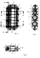
- the device is composed of two half-shells, the upper half-shell 1 and the lower half-shell 2 .
- the half-shells 1 and 2 comprise curved passage areas 5 which, when the half-shells 1, 2 are in the assembled state, together form the passage openings 8 ( figure 5 ) limit.
- the half-shells 1, 2 have contact areas 6 adjoining the passage areas 5, along which the half-shells 1, 2 lie one on top of the other in the assembled state.
- the half-shells 1, 2 form a housing which delimits a cavity 9 in which electrical connections for contacting through the cables routed through the through-openings 8 into the cavity 9 are arranged.
- the upper sealing strip 3 extends only over the length of the wall in which the passage openings 8 are formed and has curved sections adapted to the passage areas 5 and straight sections adapted to the contact areas 6 arranged between them.
- the upper sealing strip 3 is arranged in a groove provided for this purpose in the upper half-shell 1 and is preferably chemically bonded to the material of the upper half-shell 1 to form a material connection.
- the lower sealing strip 4 encloses the cavity 9 along the entire circumference and is therefore designed as a circumferential, ring-shaped seal.
- the lower sealing strip 4 like the upper sealing strip 3, has curved sections adapted to the passage areas 5 and straight sections adapted to the contact areas 6 arranged between them.
- the lower sealing strip 4 is arranged in a groove 7 of the lower half-shell 2 provided for this purpose.
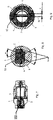
- the upper half-shell 1 has conical centering domes 10 which, when the two half-shells 1.2 are assembled, dip into corresponding receiving bores 11 in the lower half-shell 2 in order to define the relative position of the two half-shells 1.2. Furthermore, in the upper half-shell 1 and in the lower half-shell 2 there are formed through-holes 12 which are aligned with one another and which serve to receive connecting screws for pressing the two half-shells 1, 2 together. It can also be seen that the lower half-shell 2 has centering domes 13 on both sides of each through-opening 8, specifically two centering domes 13 at the front end and two centering domes 13 at the rear end of the through-opening 8, seen in the axial direction.
- the centering domes 13 are designed with retaining lugs 14 , which protrude into the respective passage opening 8 and protect the cable from twisting.
- retaining lugs 14 which protrude into the respective passage opening 8 and protect the cable from twisting.
- the lower half-shell 2 is shown with the sealing strip 4 arranged therein.
- the sealing strip 4 is preferably chemically bonded to the material of the lower half-shell 2 in order to form a material connection.
- the upper half-shell 1 is shown with the sealing strip 3 arranged therein. It can be seen that the contact areas 6 of the upper half-shell 1 comprise two parallel, bead-like elevations between which the sealing strip is arranged. Since the contact areas 6 of the upper half-shell 1 and the contact areas 6 of the lower half-shell 2 rest on one another when the half-shells 1, 2 are in the assembled state, the sealing strip 3, 4 arranged between the contact areas 6 is shielded from external influences.
- FIG. 8 shows a detailed view in the area of the sealing of the cable bushing and the interaction of the sealing strips 3 and 4 between two adjacent passage openings 8. It can be seen that the sealing strips 3 and 4 are ribbed on the surfaces facing each other, so that the two sealing strips 3, 4 Type of teeth 16 mesh. The flank angles ⁇ and ⁇ of the teeth differ in order to increase the sealing effect improve and to achieve a self-centering of the gearing.
- FIG. 9 shows the interaction of the sealing strips 3.4 in the passage area, in which the ribs of the ribbed surface have noses 17 projecting from the parting plane 18, so that the sealing strips 3.4 overlap one another in the radial direction.
- the height of the nose 17 is denoted by x and can be 1-2 mm, for example.
- the lugs 17 and the centering domes 10 are dimensioned in such a way that the centering domes 10 come into engagement before the lugs 17 when the half-shells 1, 2 are assembled.
- FIG. 10 shows a detailed view in the area of the sealing of the half-shells 1, 2 on the sides of the half-shells that are not provided with through-openings.
- the seal is only achieved on these sides by the sealing strip 4 arranged in the lower half-shell 2 .
- the sealing strip 4 lies in the groove 7, which is delimited on both sides by the contact areas 6, along which the half-shells 1, 2 lie one on top of the other and thereby shield the sealing strip 4.
- the centering mandrel 10 engages in a receiving bore 11 of the lower half-shell 2 .
- a through hole 12 is formed in the centering mandrel 10 and is aligned with a corresponding through hole 12 in the lower half-shell 2 in order to receive a connecting screw.
Priority Applications (1)
| Application Number | Priority Date | Filing Date | Title |
|---|---|---|---|
| EP21020066.3A EP4044384B1 (fr) | 2021-02-10 | 2021-02-10 | Dispositif de passage d'un câble électrique |
Applications Claiming Priority (1)
| Application Number | Priority Date | Filing Date | Title |
|---|---|---|---|
| EP21020066.3A EP4044384B1 (fr) | 2021-02-10 | 2021-02-10 | Dispositif de passage d'un câble électrique |
Publications (3)
| Publication Number | Publication Date |
|---|---|
| EP4044384A1 true EP4044384A1 (fr) | 2022-08-17 |
| EP4044384C0 EP4044384C0 (fr) | 2023-08-02 |
| EP4044384B1 EP4044384B1 (fr) | 2023-08-02 |
Family
ID=74586709
Family Applications (1)
| Application Number | Title | Priority Date | Filing Date |
|---|---|---|---|
| EP21020066.3A Active EP4044384B1 (fr) | 2021-02-10 | 2021-02-10 | Dispositif de passage d'un câble électrique |
Country Status (1)
| Country | Link |
|---|---|
| EP (1) | EP4044384B1 (fr) |
Citations (4)
| Publication number | Priority date | Publication date | Assignee | Title |
|---|---|---|---|---|
| FR2723162A1 (fr) * | 1994-07-29 | 1996-02-02 | Cab Sa | Joint annulaire d'etancheite |
| US5675124A (en) * | 1996-04-30 | 1997-10-07 | Stough; Robert Eugene | Grommet for a fiber optic enclosure |
| DE60200198T2 (de) * | 2001-04-17 | 2004-09-02 | Legrand | Abdichtung für elektrisches Kabel |
| DE102018104915A1 (de) * | 2018-03-05 | 2019-09-05 | Te Connectivity Germany Gmbh | Dichtungseinrichtung für eine Leitung sowie elektrischer Verbinder |
-
2021
- 2021-02-10 EP EP21020066.3A patent/EP4044384B1/fr active Active
Patent Citations (4)
| Publication number | Priority date | Publication date | Assignee | Title |
|---|---|---|---|---|
| FR2723162A1 (fr) * | 1994-07-29 | 1996-02-02 | Cab Sa | Joint annulaire d'etancheite |
| US5675124A (en) * | 1996-04-30 | 1997-10-07 | Stough; Robert Eugene | Grommet for a fiber optic enclosure |
| DE60200198T2 (de) * | 2001-04-17 | 2004-09-02 | Legrand | Abdichtung für elektrisches Kabel |
| DE102018104915A1 (de) * | 2018-03-05 | 2019-09-05 | Te Connectivity Germany Gmbh | Dichtungseinrichtung für eine Leitung sowie elektrischer Verbinder |
Also Published As
| Publication number | Publication date |
|---|---|
| EP4044384C0 (fr) | 2023-08-02 |
| EP4044384B1 (fr) | 2023-08-02 |
Similar Documents
| Publication | Publication Date | Title |
|---|---|---|
| EP3682515B1 (fr) | Moyens d'étanchéité pour câble et ensemble comprenant les moyens d'étanchéité | |
| DE19751844A1 (de) | Einrichtung zum Anschließen und Verbinden einer Leitung | |
| DE102016108314A1 (de) | Umspritz-Adapter | |
| EP1867024B1 (fr) | Dispositif de traversee de cable | |
| EP1088374B1 (fr) | Adaptateur de traversee pour armoire electrique | |
| DE102006062609A1 (de) | Kabeldurch-/-einführungselement zum Dichten, Klemmen, Schirmen und Leiten | |
| DE102011006928A1 (de) | Abdichtung von Gehäuse für Steckkontaktelemente | |
| EP2614565B1 (fr) | Traversée de câbles | |
| EP2742284B1 (fr) | Dispositif électrique pourvu d'un élément d'étanchéité, élément d'étanchéité pour un dispositif électrique et procédé pour rendre étanche un boîtier | |
| EP0543350A1 (fr) | Manchon de câble comprenant un boîtier divisé longitudinalement | |
| EP4044384B1 (fr) | Dispositif de passage d'un câble électrique | |
| DE102014104275A1 (de) | Kontaktierungsvorrichtung, Kontaktbolzen zur Verwendung in einer solchen und mit diesen versehene Elektronikbox | |
| DE102013111321B4 (de) | Mehrpolige elektrische Wanddurchführung | |
| DE102013113878B4 (de) | Steckverbinder mit Einzeladerabdichtung | |
| DE102005014373B3 (de) | Elektrische Steckvorrichtung | |
| EP0415136B1 (fr) | Insert pour connecteur à boîtier métallique | |
| DE202016102392U1 (de) | Umspritzadapter | |
| DE102012011449A1 (de) | Kabeldurchführung zur Hindurchführung eines Kabels durch eine Öffnung in einer Wand | |
| DE102018112222B4 (de) | Fahrzeugseitige Baugruppe eines Ladesteckverbinders für ein Fahrzeug und Verfahren zum Herstellen Derselben | |
| DE102020109786A1 (de) | Anschlusseinrichtung | |
| WO1991011835A1 (fr) | Raccord de cables rapide etanche aux liquides | |
| DE202007017488U1 (de) | Steckeranordnung | |
| DE102016006300B4 (de) | Stellantrieb mit wasserdichter Kabeldurchführung | |
| DE102022133217B3 (de) | Abgedichtete elektrische durchführung durch eine gehäusewand | |
| DE19545326C1 (de) | Anordnung zum Anschluß eines Geräte-Anschlußkabels |
Legal Events
| Date | Code | Title | Description |
|---|---|---|---|
| PUAI | Public reference made under article 153(3) epc to a published international application that has entered the european phase |
Free format text: ORIGINAL CODE: 0009012 |
|
| STAA | Information on the status of an ep patent application or granted ep patent |
Free format text: STATUS: REQUEST FOR EXAMINATION WAS MADE |
|
| 17P | Request for examination filed |
Effective date: 20211229 |
|
| AK | Designated contracting states |
Kind code of ref document: A1 Designated state(s): AL AT BE BG CH CY CZ DE DK EE ES FI FR GB GR HR HU IE IS IT LI LT LU LV MC MK MT NL NO PL PT RO RS SE SI SK SM TR |
|
| GRAP | Despatch of communication of intention to grant a patent |
Free format text: ORIGINAL CODE: EPIDOSNIGR1 |
|
| STAA | Information on the status of an ep patent application or granted ep patent |
Free format text: STATUS: GRANT OF PATENT IS INTENDED |
|
| RIC1 | Information provided on ipc code assigned before grant |
Ipc: H02G 3/22 20060101ALN20230330BHEP Ipc: H02G 3/08 20060101AFI20230330BHEP |
|
| RIC1 | Information provided on ipc code assigned before grant |
Ipc: H02G 3/22 20060101ALN20230404BHEP Ipc: H02G 3/08 20060101AFI20230404BHEP |
|
| INTG | Intention to grant announced |
Effective date: 20230421 |
|
| GRAS | Grant fee paid |
Free format text: ORIGINAL CODE: EPIDOSNIGR3 |
|
| GRAA | (expected) grant |
Free format text: ORIGINAL CODE: 0009210 |
|
| STAA | Information on the status of an ep patent application or granted ep patent |
Free format text: STATUS: THE PATENT HAS BEEN GRANTED |
|
| AK | Designated contracting states |
Kind code of ref document: B1 Designated state(s): AL AT BE BG CH CY CZ DE DK EE ES FI FR GB GR HR HU IE IS IT LI LT LU LV MC MK MT NL NO PL PT RO RS SE SI SK SM TR |
|
| REG | Reference to a national code |
Ref country code: GB Ref legal event code: FG4D Free format text: NOT ENGLISH |
|
| REG | Reference to a national code |
Ref country code: CH Ref legal event code: EP |
|
| REG | Reference to a national code |
Ref country code: DE Ref legal event code: R096 Ref document number: 502021001107 Country of ref document: DE |
|
| REG | Reference to a national code |
Ref country code: IE Ref legal event code: FG4D Free format text: LANGUAGE OF EP DOCUMENT: GERMAN |
|
| U01 | Request for unitary effect filed |
Effective date: 20230830 |
|
| U07 | Unitary effect registered |
Designated state(s): AT BE BG DE DK EE FI FR IT LT LU LV MT NL PT SE SI Effective date: 20230908 |
|
| U20 | Renewal fee paid [unitary effect] |
Year of fee payment: 4 Effective date: 20231207 |
|
| PG25 | Lapsed in a contracting state [announced via postgrant information from national office to epo] |
Ref country code: GR Free format text: LAPSE BECAUSE OF FAILURE TO SUBMIT A TRANSLATION OF THE DESCRIPTION OR TO PAY THE FEE WITHIN THE PRESCRIBED TIME-LIMIT Effective date: 20231103 |
|
| PG25 | Lapsed in a contracting state [announced via postgrant information from national office to epo] |
Ref country code: IS Free format text: LAPSE BECAUSE OF FAILURE TO SUBMIT A TRANSLATION OF THE DESCRIPTION OR TO PAY THE FEE WITHIN THE PRESCRIBED TIME-LIMIT Effective date: 20231202 |
|
| PG25 | Lapsed in a contracting state [announced via postgrant information from national office to epo] |
Ref country code: RS Free format text: LAPSE BECAUSE OF FAILURE TO SUBMIT A TRANSLATION OF THE DESCRIPTION OR TO PAY THE FEE WITHIN THE PRESCRIBED TIME-LIMIT Effective date: 20230802 Ref country code: NO Free format text: LAPSE BECAUSE OF FAILURE TO SUBMIT A TRANSLATION OF THE DESCRIPTION OR TO PAY THE FEE WITHIN THE PRESCRIBED TIME-LIMIT Effective date: 20231102 Ref country code: IS Free format text: LAPSE BECAUSE OF FAILURE TO SUBMIT A TRANSLATION OF THE DESCRIPTION OR TO PAY THE FEE WITHIN THE PRESCRIBED TIME-LIMIT Effective date: 20231202 Ref country code: HR Free format text: LAPSE BECAUSE OF FAILURE TO SUBMIT A TRANSLATION OF THE DESCRIPTION OR TO PAY THE FEE WITHIN THE PRESCRIBED TIME-LIMIT Effective date: 20230802 Ref country code: GR Free format text: LAPSE BECAUSE OF FAILURE TO SUBMIT A TRANSLATION OF THE DESCRIPTION OR TO PAY THE FEE WITHIN THE PRESCRIBED TIME-LIMIT Effective date: 20231103 |
|
| PG25 | Lapsed in a contracting state [announced via postgrant information from national office to epo] |
Ref country code: PL Free format text: LAPSE BECAUSE OF FAILURE TO SUBMIT A TRANSLATION OF THE DESCRIPTION OR TO PAY THE FEE WITHIN THE PRESCRIBED TIME-LIMIT Effective date: 20230802 |