EP4044209B1 - Einbolzensicherungsanordnung mit einem elektrisch isolierten bolzen - Google Patents
Einbolzensicherungsanordnung mit einem elektrisch isolierten bolzen Download PDFInfo
- Publication number
- EP4044209B1 EP4044209B1 EP22156321.6A EP22156321A EP4044209B1 EP 4044209 B1 EP4044209 B1 EP 4044209B1 EP 22156321 A EP22156321 A EP 22156321A EP 4044209 B1 EP4044209 B1 EP 4044209B1
- Authority
- EP
- European Patent Office
- Prior art keywords
- bolt
- fuse
- shaft
- base
- insulated
- Prior art date
- Legal status (The legal status is an assumption and is not a legal conclusion. Google has not performed a legal analysis and makes no representation as to the accuracy of the status listed.)
- Active
Links
Images




Classifications
-
- H—ELECTRICITY
- H01—ELECTRIC ELEMENTS
- H01H—ELECTRIC SWITCHES; RELAYS; SELECTORS; EMERGENCY PROTECTIVE DEVICES
- H01H85/00—Protective devices in which the current flows through a part of fusible material and this current is interrupted by displacement of the fusible material when this current becomes excessive
- H01H85/02—Details
- H01H85/20—Bases for supporting the fuse; Separate parts thereof
- H01H85/2045—Mounting means or insulating parts of the base, e.g. covers, casings
-
- H—ELECTRICITY
- H01—ELECTRIC ELEMENTS
- H01H—ELECTRIC SWITCHES; RELAYS; SELECTORS; EMERGENCY PROTECTIVE DEVICES
- H01H85/00—Protective devices in which the current flows through a part of fusible material and this current is interrupted by displacement of the fusible material when this current becomes excessive
- H01H85/02—Details
- H01H85/0241—Structural association of a fuse and another component or apparatus
-
- H—ELECTRICITY
- H01—ELECTRIC ELEMENTS
- H01H—ELECTRIC SWITCHES; RELAYS; SELECTORS; EMERGENCY PROTECTIVE DEVICES
- H01H85/00—Protective devices in which the current flows through a part of fusible material and this current is interrupted by displacement of the fusible material when this current becomes excessive
- H01H85/54—Protective devices wherein the fuse is carried, held, or retained by an intermediate or auxiliary part removable from the base, or used as sectionalisers
-
- H—ELECTRICITY
- H01—ELECTRIC ELEMENTS
- H01H—ELECTRIC SWITCHES; RELAYS; SELECTORS; EMERGENCY PROTECTIVE DEVICES
- H01H85/00—Protective devices in which the current flows through a part of fusible material and this current is interrupted by displacement of the fusible material when this current becomes excessive
- H01H85/02—Details
- H01H85/20—Bases for supporting the fuse; Separate parts thereof
-
- H—ELECTRICITY
- H01—ELECTRIC ELEMENTS
- H01H—ELECTRIC SWITCHES; RELAYS; SELECTORS; EMERGENCY PROTECTIVE DEVICES
- H01H85/00—Protective devices in which the current flows through a part of fusible material and this current is interrupted by displacement of the fusible material when this current becomes excessive
- H01H85/02—Details
- H01H85/20—Bases for supporting the fuse; Separate parts thereof
- H01H85/205—Electric connections to contacts on the base
-
- H—ELECTRICITY
- H01—ELECTRIC ELEMENTS
- H01H—ELECTRIC SWITCHES; RELAYS; SELECTORS; EMERGENCY PROTECTIVE DEVICES
- H01H85/00—Protective devices in which the current flows through a part of fusible material and this current is interrupted by displacement of the fusible material when this current becomes excessive
- H01H85/02—Details
- H01H85/22—Intermediate or auxiliary parts for carrying, holding, or retaining fuse, co-operating with base or fixed holder, and removable therefrom for renewing the fuse
-
- H—ELECTRICITY
- H01—ELECTRIC ELEMENTS
- H01R—ELECTRICALLY-CONDUCTIVE CONNECTIONS; STRUCTURAL ASSOCIATIONS OF A PLURALITY OF MUTUALLY-INSULATED ELECTRICAL CONNECTING ELEMENTS; COUPLING DEVICES; CURRENT COLLECTORS
- H01R13/00—Details of coupling devices of the kinds covered by groups H01R12/70 or H01R24/00 - H01R33/00
- H01R13/66—Structural association with built-in electrical component
- H01R13/68—Structural association with built-in electrical component with built-in fuse
-
- H—ELECTRICITY
- H01—ELECTRIC ELEMENTS
- H01H—ELECTRIC SWITCHES; RELAYS; SELECTORS; EMERGENCY PROTECTIVE DEVICES
- H01H85/00—Protective devices in which the current flows through a part of fusible material and this current is interrupted by displacement of the fusible material when this current becomes excessive
- H01H85/02—Details
- H01H85/0241—Structural association of a fuse and another component or apparatus
- H01H2085/025—Structural association with a binding post of a storage battery
-
- H—ELECTRICITY
- H01—ELECTRIC ELEMENTS
- H01H—ELECTRIC SWITCHES; RELAYS; SELECTORS; EMERGENCY PROTECTIVE DEVICES
- H01H2223/00—Casings
- H01H2223/01—Mounting on appliance
- H01H2223/024—Screw
-
- H—ELECTRICITY
- H01—ELECTRIC ELEMENTS
- H01H—ELECTRIC SWITCHES; RELAYS; SELECTORS; EMERGENCY PROTECTIVE DEVICES
- H01H85/00—Protective devices in which the current flows through a part of fusible material and this current is interrupted by displacement of the fusible material when this current becomes excessive
- H01H85/02—Details
- H01H85/04—Fuses, i.e. expendable parts of the protective device, e.g. cartridges
- H01H85/05—Component parts thereof
- H01H85/143—Electrical contacts; Fastening fusible members to such contacts
- H01H85/15—Screw-in contacts
-
- H—ELECTRICITY
- H01—ELECTRIC ELEMENTS
- H01H—ELECTRIC SWITCHES; RELAYS; SELECTORS; EMERGENCY PROTECTIVE DEVICES
- H01H85/00—Protective devices in which the current flows through a part of fusible material and this current is interrupted by displacement of the fusible material when this current becomes excessive
- H01H85/02—Details
- H01H85/20—Bases for supporting the fuse; Separate parts thereof
- H01H85/2005—Bases for supporting the fuse; Separate parts thereof for use with screw-in type fuse
Definitions
- Embodiments of the present disclosure relate to single bolt fuses and, more particularly, to a novel way to attach the single bolt fuse to a female battery or power cable.
- Fuses are current-sensitive devices designed to serve as the intentional weak link in an electronic circuit. Fuses provide protection of discrete components or of complete circuits by reliably melting under current overload conditions. Fuses come in a variety of packages and ratings to suit to their intended application.
- Single bolt fuses also known as battery terminal fuses, are a particular type of fuse package in which the fuse is attached to a device or circuitry by a threaded connection, such as a bolt or stud.
- the fuse includes a hole through which a single bolt may be inserted to mechanically connect the fuse to the device or circuit.
- the bolts are specially adapted, such as by being insulated or otherwise materially treated, so that they do not disrupt or become part of a current path through the fuses, ensuring that the single bolt fuses operate as designed.
- the specially treated bolt is separated from the fuse, the fuse is attached to the circuit or device to be protected, the bolt is inserted through the hole in the fuse.
- the bolt has an integrated nut, or bolt may be secured by a separate nut. Because of the assembly needed with single bolt fuses, the bolt (and nut, if present) may become separated from the fuse and lost. Customers may be tempted to replace the lost bolt with a standard bolt that is not specially adapted for the single bolt fuse. Unfortunately, this results in the single bolt fuse not functioning as designed. Further, the single bolt fuse is designed to be connected between a power terminal and either a battery terminal or a bus bar, which somewhat limits the applications in which the fuse may be used.
- 'A circuit protection assembly includes a mounting block, a unitary fuse assembly, a post assembly and a plug connector.
- the unitary fuse assembly is disposed the mounting block and includes a plurality of fuses each of which is defined by a portion of a bus plate disposed on the lower surface of the mounting block to form a first terminal of the fuse, a second terminal disposed at least partially on the upper surface of the mounting block and a fuse element connecting the first terminal and the second terminal.
- the post assembly is disposed at least partially within the mounting block and a post extending from the block.
- the plug connector extends from a portion of the first terminal of at least one of the plurality of fuses.'
- An exemplary embodiment of a fuse assembly in accordance with the present disclosure includes an insulated steel bolt and a metal terminal.
- the insulated steel bolt includes a shaft that is part threaded and part insulated. Connected to the shaft, the insulated steel bolt also includes a base, which is a rectangular cube having a first dimension. The shaft is positioned vertically atop one side of the base.
- the metal terminal features a bolt base receptacle, also shaped like a rectangular cube, and having a hollow interior with a second dimension that is greater than that of the base.
- the base of the steel bolt fits into the hollow interior of the bolt base receptacle.
- the metal terminal also has a threaded shaft on one side of the bolt base receptacle. The shaft of the insulated steel bolt is to be fed through a cylindrical opening of a fuse.
- a single bolt fuse assembly and method to connect a single bolt fuse to a circuit or device are disclosed.
- the single bolt fuse assembly enables the single bolt fuse to be used on any electrical device having a hole suitable for receiving a threaded shaft and connectable to a circuit or device that electrically connects to a female battery or power cable.
- the apparatus includes a separate high-conductive metal terminal that mates with the stud that mechanically attaches the fuse between the electrical devices.
- the stud is insulated, thus isolating the bolt from becoming part of the electrical circuit and ensuring proper operation of the fuse. By mechanically attaching the stud to the metal terminal, the stud is unlikely to get separated from the fuse.
- the metal terminal and stud may be part of a kit available to customers who purchase the single bolt fuse.
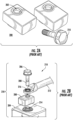
- FIG. 1 is a representative drawing of a 250A single bolt fuse 100 for providing circuit protection, according to the prior art.
- the single bolt fuse 100 features a receptacle 102, such as a cylindrical hole, for receiving a like-sized threaded bolt, known as a stud.
- the fuse simply slips over the bolt or stud.
- Two studs 110A and 110B are also shown, the stud 110A featuring a threaded shaft 104 and the stud 110B featuring a threaded shaft 106 and further including a flange nut 108.
- the studs 110 are designed to be electrically isolated when inserted through the fuse hole 102 of the single bolt fuse 100. Accordingly, the studs 110 may be insulated or otherwise materially treated so that the studs do not become part of the electrical path through which current flows when the single bolt fuse 100 is connected to a circuit or device to be protected.
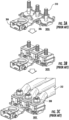
- FIGs. 2A and 2B illustrate another single bolt fuse 200, according to the prior art.
- Two fuses 200 are depicted in FIG. 2A , each including a hole 202 for receiving a threaded stud 210.
- the stud 210 includes an insulated, threaded portion 208 and an integrated nut 206.
- the fuse 200 is to be connected to a battery 204, which has a receiving aperture 214 sized to support the threaded portion 208 of the stud 210.
- a sealed power cable 212 to connect the battery 204 to other circuitry/device (not shown) also includes a receiving aperture 216.
- the single bolt fuse 200 is placed between the battery 204 and the sealed power cable 212, with the insulated bolt 210 threading through respective holes 214 and 216, sealing the components together.
- FIGs. 3A-3C illustrate an assembly 302 featuring single bolt fuses 300, according to the prior art, with the assembly shown in three parts (302A, 302B, and 302C).
- three threaded studs 310 are inserted through a busbar 306, from the bottom.
- a battery terminal 304 is then placed over the center stud.
- Three single bolt fuses 300 are then placed on the studs 310.
- Output power cables 312 are then placed on top of the fuses 300, also over the studs 310, as the cables include ring terminals for this purpose.
- the components are then secured with nuts 308.
- the fuses 100, 200, and 300 are designed to be used with their respective studs 110, 210, and 310.
- the studs are insulated to isolate current so that the current passes through the fuse (and not the stud), enabling the fuse to protect the circuit (e.g., the circuit or device connected to the output cable 212 ( FIG. 2B ) or output cable 312 ( FIG. 3C ) ) as intended.
- the fuse 200 includes a breakaway portion therein that will break, protecting any circuitry connected to the sealed cable 212.
- the assembly 218 thus operates as designed.
- the insulated stud 210 is replaced with an uninsulated stud not designed to be used with the fuse 200, current will flow from the battery 204, through the uninsulated stud, and through the sealed cable 212, completely bypassing the fuse 200. The same will happen in the other direction: current will flow from the circuitry to be protected (not shown) through the sealed cable 212, through the uninsulated stud, and to the battery 204, completely bypassing the fuse 200. Put another way, the uninsulated stud will electrically connect the top and the bottom of the fuse, removing the fuse from the circuit. Thus, the use of a stud not designed to be used with the fuse 200 will prevent the fuse from operating as designed to protect the circuitry. Similar problems will exist for the fuses 100 and 300 if they are used with uninsulated studs.
- the fuses are connected, at one end, to the battery or power cable and, at the other end, to either a battery terminal or to a bus bar.
- the fuse 200 is positioned between the power cable 212 and the battery 204.
- the fuse 300 is positioned between the power cables 312 and the busbar 306 (which is connected to the battery terminal 304).
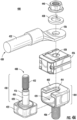
- FIGs. 4A-4C An alternative is provided in the apparatus of FIGs. 4A-4C , a single bolt fuse assembly with an electrically isolated bolt 400, according to exemplary embodiments.
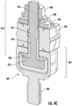
- FIGs. 4A and 4B are exploded perspective views while FIG. 4C is a perspective cutaway view of the single bolt fuse assembly 400.
- the single bolt fuse assembly 400 features a metal terminal 402, an insulated steel bolt 408 (also known herein as a stud 408), a single bolt fuse 426, and a female battery or power cable 430, which are joined together as described herein.
- the single bolt fuse assembly 400 maintains a connection between the insulated steel bolt 408 and the single bolt fuse 426, thus ensuring proper functioning of the fuse as a protector of connected circuits or devices.
- the metal terminal 402 also known as the "landing pad" of the fuse assembly 400, includes a bolt base receptacle 404 and a threaded shaft 406.
- the threaded shaft 406 enables connection of the single bolt fuse assembly 400 with any electrical device having a threaded receiving aperture.
- the metal terminal 402 further includes an adjacent side opening 424, revealing a hollow interior, as well as an inset portion 414.
- the threaded shaft 406 and the bolt base receptacle 404 of the metal terminal 402, including the opening 424 and the inset portion 414, are machined from a unitary metal piece made of electrically conductive material, such as copper or a copper alloy.
- the steel bolt or stud 408 of the single bolt fuse assembly 400 features a shaft 410 that has a threaded portion 412, an unthreaded portion 416, an insulated portion 418, an optional integrated washer 420, and a base 422.
- the integrated washer 420 and the base 422 are also insulated so as to isolate them from current transmitted through the assembly.
- the integrated washer 420 also helps to withstand pressure after the assembly 400 is secured by the nut 440.
- the insulation of the base 422 is sufficient to prevent current flow through the stud and to withstand high mechanical pressures during torque of the nut 440.
- the stud 408 may be configured without the integrated washer 420.
- the insulated components of the assembly 400 are insulated using electrically insulating material, such as overmolded plastic, though other insulation materials may also be used.
- the bolt base receptacle 404 is a rectangular cube shape of a first dimension.
- the hollow interior of the bolt base receptacle 404 which is a second dimension smaller than the first dimension, is disposed on one side adjacent the side with the threaded shaft 406.
- the base 422 of the stud 408, which is a third dimension fits snugly into the bolt base receptacle 404 of the metal terminal 402.
- the second dimension is slightly greater than the third dimension, allowing the base 422 to fit into the hollow interior via the opening 424 of the base receptacle 404.
- the inset portion 404 of the bolt base receptacle 404 is disposed opposite the threaded shaft 406, and the shaft 410 of the stud 408 fits into the inset portion 404 as the base 422 is laterally presented into the base receptacle 404.
- the threaded shaft 406 of the metal terminal 402 appears to be along the same axis as the shaft 410 of the stud 408, in an exemplary embodiment.
- the two shafts 406 and 410 may be in different axes.
- a more elongated rectangular cube-shaped receptacle may result in the shaft 406 of the metal terminal 402 being in one axis and the shaft 410 of the stud 408 being in a different axis, with the two axes being parallel to one another.
- the inset portion 414 may be machined into a different side of the bolt base receptacle 404 (a side not opposite the threaded shaft 406). This would result in the shaft 410 of the stud being in an axis orthogonal to the threaded shaft 406.
- the opening 424 which is now on a side adjacent to the threaded shaft 406, may instead be on the side opposite the threaded shaft, where the inset portion 414 is now located, in which case the shaft 410 of the stud would be orthogonal to the shaft 406 of the metal terminal 402.
- the landing pad 402 may be machined to receive the base 422 and shaft 410 of the stud 408 without departing from the spirit of this disclosure.
- the insulated steel bolt 408 may be captured or mechanically locked in the bolt base receptacle 404.
- orbital riveting, a mechanical bottleneck, a secondary lock, or other means are employed to mechanically lock the bolt 408 to the metal terminal 402.
- the fuse 426 of the single bolt fuse assembly 400 includes a cylindrical opening 428, a shaft receptacle, for receiving the shaft 410 of the stud 408.
- the single bolt fuse 426 is disposed atop and adjacent to a top surface of the bolt base receptacle 404, as illustrated in the cutaway view of FIG. 4C .
- both the unthreaded portion 416 and the insulated portion 418 of the shaft 410 are disposed within the shaft receptacle 428 of the single bolt fuse 426.
- the shaft 410 is insulated from a bottom portion of the fuse terminal, ensuring that the bolt will not conduct the fuse element (not shown) within the fuse 426. The insulation may be higher than is shown.
- the threaded portion 412 of the shaft 410 extends to the top of the fuse 426.
- the insulating layer/portion 418 and the insulating washer 420 of the single bolt fuse assembly 400 isolates the center bolt 408 from the fuse 426.
- the single bolt fuse 426 may also be known as a coaxial fuse, as the two terminals that are connected by the fuse element are actual coaxial. That is, their holes are concentric and placed in different (parallel) planes. This is in contrast to some fuses which have a linear shape with the fuse element in the middle, with a terminal on each side.
- the single bolt fuse 426 includes within its housing a fusing element (the intentional weak link that breaks upon the occurrence of an overload event, such as overcurrent, overvoltage, or both), connection means for connecting the fusing element to terminals (ensuring that the fusing element is part of a closed circuit), and fusing powder.
- This part of the fuse 426 containing the fuse element is known herein as the fuse element housing.
- the shaft receptacle 428 is isolated from the fusing element housing.
- the fusing element housing of the single bolt fuse 426 may thus be thought of as an annular housing, shaped like a rectangular donut, with the shaft receptacle 428 being both physically and electrically isolated from the fusing element housing.
- the single bolt fuse assembly 400 includes the female battery or power cable 430, which includes a cable 432 and a high-current electrical (ring) terminal 436.
- the cable 432 attaches the fuse 426 at one end to a circuit or device to be protected (not shown) while the threaded shaft 406 of the landing pad 402 attaches the fuse at the other end to virtually any electrical component that has a hole through which the landing pad may be threaded, enabling the electrical component to be electrically connected to the fuse 426.
- the threaded portion 412 of the stud 408 is fed through the ring terminal 436, and the female battery or power cable 430 is attached to the assembly by an optional washer 438 and a nut 440.
- the nut 440 is a flange nut, but a regular nut may also be used as long as torque loosening is avoided during use of the assembly 400.
- the washer and the nut are not part of the current path, and so need not be insulated. This means that, if lost, the optional washer and nut may be replaced without compromising the operation of the fuse 426.
- the low-resistant landing pad 402 lets current flow through the fuse 426 and the battery or power cable 430.
- the steel insulated bolt 408 guarantees a high torque to fix the assembly 400 without being involved in the electrical flow.
- FIGs. 5A-5C are perspective cutaway illustrations of a single bolt fuse 500 suitable for the single bolt fuse assembly 400, according to exemplary embodiments.
- a cover portion 502 when removed, reveals a fusing element 506 disposed to one side of the fuse 500.
- a shaft receptacle 504 is for receiving an insulated shaft, such as the shaft 410 described above. The shaft receptacle 504 is both physically and electrically isolated from the fusing element 506.
- FIG. 6 is a perspective illustration of a configuration 600 featuring the single bolt fuse assembly with an electrically isolated bolt 400 connected to a relay 602, according to exemplary embodiments.
- the single bolt fuse assembly 400 is connected to the relay 602 by the threaded shaft 406 of the landing pad 402.
- the relay 602 includes a threaded hole (not shown) for receiving the threaded shaft 406, thus establishing an electrical connection between the relay 602 and the fuse 426.
- the configuration 600 may further be connected to an electrical circuit or device via the female battery or power cable (such as female battery or power cable 430 in FIGs. 3A and 3B ).
- the configuration 600 is merely illustrative.
- the single bolt fuse assembly 400 is designed to connect between 1) any electrical device that includes a threaded hole for receiving the threaded shaft 406 of the landing pad 402 and 2) any electrical device or circuit that is electrically connected using the female battery or power cable.
- Single bolt fuses such as the prior art single bolt fuses described and illustrated above, feature M6, M8, and M10 sized threaded holes for connecting with M6, M8, and M10 insulated studs, respectively.
- the single bolt fuse assembly 400 may be designed with a threaded shaft of any size, sized to fit with a single bolt fuse having a hole of a similar size. The examples herein are not limited in regard to the size of the threaded shaft or the threaded hole.
- FIG. 7 is a flow diagram illustrating a method 700 of assembling a single bolt fuse assembly with an electrically isolated bolt, such as the single bolt fuse assembly 400 described and illustrated above.
- the reference numbers of the single bolt fuse assembly 400 are given in parentheses, though the method steps may apply to other configurations of single bolt fuse assemblies.
- the base (422) can be secured inside the bolt base receptacle (404), such as by orbital riveting, mechanical bottleneck, secondary lock, or other means (block 704).
- the shaft (410) is next inserted through the receiving aperture or shaft receptacle (428) of the single bolt fuse (426) until the fuse is disposed atop the bolt base receptacle (404) of the landing pad (402) (block 706).
- the insulated portion (418) of the shaft (410) is partially inserted into the receptacle (428).
- the ring terminal (436) of the female battery or power cable (430) is positioned over the shaft (410) of the stud (408) until the ring terminal (436) is flush against the top surface of the single bolt fuse (426) (block 708).
- the washer (438) ), if present, and nut (440 are disposed over the shaft (410) of the stud (408), and secured tightly thereon (block 710).
- the shaft (410) of the stud (408) is secured by a nut having an integrated washer, such as a flange nut, a trilobate nut, or other type of nut that can be used without a washer.
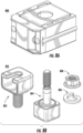
- FIGs. 8A and 8B are illustrations of a single bolt fuse 800 and a single bolt fuse assembly kit 810, respectively, according to exemplary embodiments.
- Customers may want to assemble a single bolt fuse assembly, such as the single bolt fuse assembly 400 ( FIGs. 4A-4C ) or a configuration, such as the configuration 600 ( FIG. 6 ) for connecting a single bolt fuse to an electrical device.
- the manufacturer may provide a variety of single bolt fuses for purchase, and, separately, may provide a variety of single bolt fuse assembly kits. Or the manufacturer may provide a kit including the fuse with the assembly.
- the single bolt fuse 800 FIG.
- the customer may purchase a single bolt fuse assembly kit 810 ( FIG. 8B ) containing the metal terminal 802 (landing pad), steel bolt including insulated base 804, optional washer 806, and nut 808, which is properly sized for the single bolt fuse.
- the shaft of the steel bolt 804 will fit through the hole of the single bolt fuse.
- the customer will likely already have the female battery or power cable (e.g., threaded battery or power cable 430 in FIGs. 4A and 4B ), as this component may be part of the circuitry or device in their possession.
- the female battery or power cable is not part of the assembly kit 810.
- the manufacture may sell the single bolt fuse 800 along with the assembly kit 810.
Landscapes
- Engineering & Computer Science (AREA)
- Power Engineering (AREA)
- Fuses (AREA)
Claims (9)
- Sicherungsanordnung (400), die Folgendes umfasst:einen isolierten Stahlbolzen (408), der Folgendes umfasst:einen Schaft (410) mit einem Gewindeabschnitt (412) und einem isolierten Abschnitt (418); undeine mit dem Schaft (410) gekoppelte Basis (422), wobei es sich bei der Basis (422) um einen Quader mit einer ersten Abmessung handelt, wobei der Schaft (410) vertikal auf einer Seite der Basis (422) angeordnet ist;einen Metallanschluss (402), der Folgendes umfasst:eine Bolzenbasisaufnahme (404) mit einem zweiten Quader, wobei der zweite Quader einen hohlen Innenraum mit einer zweiten Abmessung umfasst, wobei die zweite Abmessung größer als die erste Abmessung ist, wobei die Basis (422) in den hohlen Innenraum der Bolzenbasisaufnahme (404) passt; undeinen auf einer Seite der Bolzenbasisaufnahme (404) angeordneten Gewindeschaft (406), wobei der Schaft (410) des isolierten Stahlbolzens (408) durch eine zylindrische Öffnung einer Sicherung zu führen ist.
- Sicherungsanordnung (400) nach Anspruch 1, wobei die Bolzenbasisaufnahme (404) ferner eine Öffnung umfasst, um die Basis (422) in den hohlen Innenraum aufzunehmen, wobei die Öffnung vorzugsweise auf einer Oberfläche der Bolzenbasisaufnahme (404) neben dem Gewindeschaft (406) liegt.
- Sicherungsanordnung (400) nach Anspruch 1 oder 2, wobei die Bolzenbasisaufnahme (404) ferner einen eingesetzten Abschnitt (414) umfasst, um den Schaft (410) des isolierten Stahlbolzens (408) aufzunehmen, wenn die Basis (422) in dem hohlen Innenraum aufgenommen ist.
- Sicherungsanordnung (400) nach einem der vorhergehenden Ansprüche, wobei der isolierte Stahlbolzen (408) ferner eine isolierte Unterlegscheibe (420) umfasst, wobei die isolierte Unterlegscheibe (420) an einem unteren Abschnitt des Schafts (410) angeordnet ist und auf der Oberseite der Basis (422) liegt.
- Sicherungsanordnung (400) nach einem der vorhergehenden Ansprüche, wobei eine oder mehrere der folgenden Aussagen zutreffen:- die Basis (422) ist mit einem elektrisch isolierenden Umspritzmaterial isoliert;- die Bolzenbasisaufnahme (404) und der Gewindeschaft (406) des Metallanschlusses (402) sind aus einem einheitlichen, elektrisch leitenden Material gefertigt;- sie umfasst ferner eine Mutter (440) und eine Unterlegscheibe (438), wobei die Unterlegscheibe an dem Schaft (410) des isolierten Stahlbolzens (408) befestigt ist, wobei der Schaft (410) vorzugsweise von ausreichender Länge ist, um durch einen Ringanschluss eines weiblichen Kabels zu passen, bevor die Mutter (440) an dem Schaft (410) befestigt wird.
- Sicherungsanordnung (400) nach Anspruch 2, wobei die Bolzenbasisaufnahme (404) sechs Seiten umfasst und die Öffnung auf einer ersten Seite der sechs Seiten liegt.
- Sicherungsanordnung (400) nach Anspruch 6, wobei der Gewindeschaft (406) orthogonal zu einer zweiten Seite der sechs Seiten angeordnet ist, wobei die zweite Seite vorzugsweise an die erste Seite angrenzt.
- Sicherungsanordnung (400) nach einem der Ansprüche 6 und 7, wobei der Gewindeschaft (406) des Metallanschlusses (402) und der Schaftabschnitt (410) des isolierten Stahlbolzens (408) in einer einheitlichen Achse angeordnet sind.
- Sicherungsanordnung (400) nach einem der Ansprüche 6 bis 8, wobei die Bolzenbasisaufnahme (404) und der Gewindeschaft (406) aus einem einheitlichen, elektrisch leitenden Material gefertigt sind.
Applications Claiming Priority (1)
| Application Number | Priority Date | Filing Date | Title |
|---|---|---|---|
| US17/173,715 US11195683B1 (en) | 2021-02-11 | 2021-02-11 | Single bolt fuse assembly with an electrically isolated bolt |
Publications (3)
| Publication Number | Publication Date |
|---|---|
| EP4044209A2 EP4044209A2 (de) | 2022-08-17 |
| EP4044209A3 EP4044209A3 (de) | 2022-10-12 |
| EP4044209B1 true EP4044209B1 (de) | 2024-04-24 |
Family
ID=78818735
Family Applications (1)
| Application Number | Title | Priority Date | Filing Date |
|---|---|---|---|
| EP22156321.6A Active EP4044209B1 (de) | 2021-02-11 | 2022-02-11 | Einbolzensicherungsanordnung mit einem elektrisch isolierten bolzen |
Country Status (3)
| Country | Link |
|---|---|
| US (3) | US11195683B1 (de) |
| EP (1) | EP4044209B1 (de) |
| CN (1) | CN114927393A (de) |
Families Citing this family (1)
| Publication number | Priority date | Publication date | Assignee | Title |
|---|---|---|---|---|
| US11817284B1 (en) * | 2022-09-12 | 2023-11-14 | Littelfuse, Inc. | Unsealed single fuse holder |
Family Cites Families (21)
| Publication number | Priority date | Publication date | Assignee | Title |
|---|---|---|---|---|
| US4358633A (en) * | 1979-12-21 | 1982-11-09 | Reynolds Jr James W | Electrical bus bar assembly and method of manufacture |
| EP0699565B1 (de) * | 1994-08-24 | 2000-12-13 | The Whitaker Corporation | Batterieklemme mit Sicherung für Kraftfahrzeuge und ihre Verbindung |
| DE19963622A1 (de) * | 1999-12-29 | 2001-07-12 | Bosch Gmbh Robert | Elektrische Sicherung für Drehstromgeneratoren mit Gleichrichter |
| US6302709B1 (en) * | 2000-06-05 | 2001-10-16 | Power-One, Inc. | Multiple function high current interconnect with integrated bus bar |
| DE10062938A1 (de) * | 2000-12-16 | 2002-06-27 | Itt Mfg Enterprises Inc | Vorrichtung zum Verbinden von Kabeln mit einem Geräteanschluß |
| US6902434B2 (en) * | 2002-07-23 | 2005-06-07 | Cooper Technologies Company | Battery fuse bus bar assembly |
| US6855008B1 (en) * | 2003-10-06 | 2005-02-15 | Royal Die & Stamping Co., Inc. | Fuse holder with adjustable terminals |
| US20060223384A1 (en) * | 2005-03-31 | 2006-10-05 | Schuh Anthony E | Battery terminal clamp |
| US7172462B1 (en) * | 2005-08-15 | 2007-02-06 | Yazaki North America, Inc. | Fuse |
| US7924137B2 (en) * | 2007-09-10 | 2011-04-12 | Cooper Technologies Company | Battery fuse assembly |
| US8269596B2 (en) * | 2009-12-23 | 2012-09-18 | Cooper Technologies Company | Universal dual stud modular fuse holder assembly for bussed and non-bussed power connections |
| US8665056B2 (en) * | 2010-05-18 | 2014-03-04 | Littlefuse, Inc. | Fuse assembly |
| DE202011050310U1 (de) * | 2011-05-31 | 2011-07-11 | Lisa Dräxlmaier GmbH | Abgewinkelte Midi- oder Schmelzsicherung |
| JP5912610B2 (ja) * | 2012-02-07 | 2016-04-27 | 矢崎総業株式会社 | ねじ締めブロックの係止構造 |
| JP5955731B2 (ja) * | 2012-10-03 | 2016-07-20 | 矢崎総業株式会社 | バスバの配置構造 |
| US8764494B2 (en) * | 2012-10-04 | 2014-07-01 | Marathon Special Products | Power terminal block |
| US9824840B2 (en) * | 2014-09-05 | 2017-11-21 | Littelfuse, Inc. | Mechanical disconnect switch with integrated fuse protection |
| JP6262159B2 (ja) * | 2015-01-14 | 2018-01-17 | 矢崎総業株式会社 | ヒューズユニット |
| US10040412B2 (en) * | 2016-05-10 | 2018-08-07 | Deere & Company | Utility vehicle power distribution module |
| CN110574136B (zh) * | 2017-04-18 | 2022-02-11 | 德尔福技术有限公司 | 保险丝组件 |
| US11417490B2 (en) * | 2018-12-20 | 2022-08-16 | Littelfuse, Inc. | Sealed battery fuse module with energy dissipating cap |
-
2021
- 2021-02-11 US US17/173,715 patent/US11195683B1/en active Active
- 2021-10-20 US US17/506,063 patent/US11469070B2/en active Active
-
2022
- 2022-02-11 CN CN202210128986.5A patent/CN114927393A/zh active Pending
- 2022-02-11 EP EP22156321.6A patent/EP4044209B1/de active Active
- 2022-08-24 US US17/894,239 patent/US11842876B2/en active Active
Also Published As
| Publication number | Publication date |
|---|---|
| CN114927393A (zh) | 2022-08-19 |
| EP4044209A2 (de) | 2022-08-17 |
| US20220406551A1 (en) | 2022-12-22 |
| US11469070B2 (en) | 2022-10-11 |
| US20220277918A1 (en) | 2022-09-01 |
| US11195683B1 (en) | 2021-12-07 |
| US11842876B2 (en) | 2023-12-12 |
| EP4044209A3 (de) | 2022-10-12 |
Similar Documents
| Publication | Publication Date | Title |
|---|---|---|
| CA2396075C (en) | Battery fuse bus bar assembly | |
| US7891999B2 (en) | Fully insulated fuse test and ground device | |
| US4884050A (en) | Blade terminal tap fuse | |
| US7192319B1 (en) | Insulated cable termination assembly and method of fabrication | |
| US8870609B2 (en) | Attachment apparatus usable in circuit interrupter environment and structured to connect a ring terminal to the circuit interrupter | |
| JPH0845405A (ja) | パイロ技術高電流保護素子 | |
| WO1996000456A1 (en) | Automotive blade type fuse block terminal adapter | |
| US10079131B2 (en) | Mechanical disconnect switch with integrated fuse protection | |
| US7695300B2 (en) | Electrically insulated conductor connection assemblies and associated method | |
| EP4044209B1 (de) | Einbolzensicherungsanordnung mit einem elektrisch isolierten bolzen | |
| US5731944A (en) | Circuit protecting device for an automotive wiring harness | |
| US11869739B2 (en) | Attaching an isolated single stud fuse to an electrical device | |
| US6234850B1 (en) | Electrical terminal arrangement | |
| TWI376712B (en) | Switchable fused power distribution block | |
| EP0806783A2 (de) | Kontaktelement | |
| JPH0950868A (ja) | コード付き電源プラグ | |
| US20240055210A1 (en) | Distributor block and method for producing distributor blocks | |
| US20070236322A1 (en) | Fuse having connectable terminals | |
| US11823857B2 (en) | Fuse module with clamped fuse installation | |
| JPH03163769A (ja) | 電気接続具 | |
| JP2002008516A (ja) | 電線保護材 |
Legal Events
| Date | Code | Title | Description |
|---|---|---|---|
| PUAI | Public reference made under article 153(3) epc to a published international application that has entered the european phase |
Free format text: ORIGINAL CODE: 0009012 |
|
| STAA | Information on the status of an ep patent application or granted ep patent |
Free format text: STATUS: THE APPLICATION HAS BEEN PUBLISHED |
|
| AK | Designated contracting states |
Kind code of ref document: A2 Designated state(s): AL AT BE BG CH CY CZ DE DK EE ES FI FR GB GR HR HU IE IS IT LI LT LU LV MC MK MT NL NO PL PT RO RS SE SI SK SM TR |
|
| PUAL | Search report despatched |
Free format text: ORIGINAL CODE: 0009013 |
|
| AK | Designated contracting states |
Kind code of ref document: A3 Designated state(s): AL AT BE BG CH CY CZ DE DK EE ES FI FR GB GR HR HU IE IS IT LI LT LU LV MC MK MT NL NO PL PT RO RS SE SI SK SM TR |
|
| RIC1 | Information provided on ipc code assigned before grant |
Ipc: H01H 85/20 20060101AFI20220906BHEP |
|
| STAA | Information on the status of an ep patent application or granted ep patent |
Free format text: STATUS: REQUEST FOR EXAMINATION WAS MADE |
|
| 17P | Request for examination filed |
Effective date: 20230411 |
|
| RBV | Designated contracting states (corrected) |
Designated state(s): AL AT BE BG CH CY CZ DE DK EE ES FI FR GB GR HR HU IE IS IT LI LT LU LV MC MK MT NL NO PL PT RO RS SE SI SK SM TR |
|
| GRAP | Despatch of communication of intention to grant a patent |
Free format text: ORIGINAL CODE: EPIDOSNIGR1 |
|
| STAA | Information on the status of an ep patent application or granted ep patent |
Free format text: STATUS: GRANT OF PATENT IS INTENDED |
|
| INTG | Intention to grant announced |
Effective date: 20240125 |
|
| GRAS | Grant fee paid |
Free format text: ORIGINAL CODE: EPIDOSNIGR3 |
|
| GRAA | (expected) grant |
Free format text: ORIGINAL CODE: 0009210 |
|
| STAA | Information on the status of an ep patent application or granted ep patent |
Free format text: STATUS: THE PATENT HAS BEEN GRANTED |
|
| AK | Designated contracting states |
Kind code of ref document: B1 Designated state(s): AL AT BE BG CH CY CZ DE DK EE ES FI FR GB GR HR HU IE IS IT LI LT LU LV MC MK MT NL NO PL PT RO RS SE SI SK SM TR |
|
| REG | Reference to a national code |
Ref country code: GB Ref legal event code: FG4D |
|
| REG | Reference to a national code |
Ref country code: CH Ref legal event code: EP |
|
| P01 | Opt-out of the competence of the unified patent court (upc) registered |
Effective date: 20240409 |
|
| REG | Reference to a national code |
Ref country code: DE Ref legal event code: R096 Ref document number: 602022002969 Country of ref document: DE |
|
| REG | Reference to a national code |
Ref country code: IE Ref legal event code: FG4D |
|
| REG | Reference to a national code |
Ref country code: LT Ref legal event code: MG9D |
|
| REG | Reference to a national code |
Ref country code: NL Ref legal event code: MP Effective date: 20240424 |
|
| REG | Reference to a national code |
Ref country code: AT Ref legal event code: MK05 Ref document number: 1680563 Country of ref document: AT Kind code of ref document: T Effective date: 20240424 |
|
| PG25 | Lapsed in a contracting state [announced via postgrant information from national office to epo] |
Ref country code: NL Free format text: LAPSE BECAUSE OF FAILURE TO SUBMIT A TRANSLATION OF THE DESCRIPTION OR TO PAY THE FEE WITHIN THE PRESCRIBED TIME-LIMIT Effective date: 20240424 |
|
| PG25 | Lapsed in a contracting state [announced via postgrant information from national office to epo] |
Ref country code: NL Free format text: LAPSE BECAUSE OF FAILURE TO SUBMIT A TRANSLATION OF THE DESCRIPTION OR TO PAY THE FEE WITHIN THE PRESCRIBED TIME-LIMIT Effective date: 20240424 |
|
| PG25 | Lapsed in a contracting state [announced via postgrant information from national office to epo] |
Ref country code: IS Free format text: LAPSE BECAUSE OF FAILURE TO SUBMIT A TRANSLATION OF THE DESCRIPTION OR TO PAY THE FEE WITHIN THE PRESCRIBED TIME-LIMIT Effective date: 20240824 |
|
| PG25 | Lapsed in a contracting state [announced via postgrant information from national office to epo] |
Ref country code: BG Free format text: LAPSE BECAUSE OF FAILURE TO SUBMIT A TRANSLATION OF THE DESCRIPTION OR TO PAY THE FEE WITHIN THE PRESCRIBED TIME-LIMIT Effective date: 20240424 |
|
| PG25 | Lapsed in a contracting state [announced via postgrant information from national office to epo] |
Ref country code: HR Free format text: LAPSE BECAUSE OF FAILURE TO SUBMIT A TRANSLATION OF THE DESCRIPTION OR TO PAY THE FEE WITHIN THE PRESCRIBED TIME-LIMIT Effective date: 20240424 Ref country code: FI Free format text: LAPSE BECAUSE OF FAILURE TO SUBMIT A TRANSLATION OF THE DESCRIPTION OR TO PAY THE FEE WITHIN THE PRESCRIBED TIME-LIMIT Effective date: 20240424 |
|
| PG25 | Lapsed in a contracting state [announced via postgrant information from national office to epo] |
Ref country code: GR Free format text: LAPSE BECAUSE OF FAILURE TO SUBMIT A TRANSLATION OF THE DESCRIPTION OR TO PAY THE FEE WITHIN THE PRESCRIBED TIME-LIMIT Effective date: 20240725 |
|
| PG25 | Lapsed in a contracting state [announced via postgrant information from national office to epo] |
Ref country code: PT Free format text: LAPSE BECAUSE OF FAILURE TO SUBMIT A TRANSLATION OF THE DESCRIPTION OR TO PAY THE FEE WITHIN THE PRESCRIBED TIME-LIMIT Effective date: 20240826 |
|
| PG25 | Lapsed in a contracting state [announced via postgrant information from national office to epo] |
Ref country code: ES Free format text: LAPSE BECAUSE OF FAILURE TO SUBMIT A TRANSLATION OF THE DESCRIPTION OR TO PAY THE FEE WITHIN THE PRESCRIBED TIME-LIMIT Effective date: 20240424 |
|
| PG25 | Lapsed in a contracting state [announced via postgrant information from national office to epo] |
Ref country code: AT Free format text: LAPSE BECAUSE OF FAILURE TO SUBMIT A TRANSLATION OF THE DESCRIPTION OR TO PAY THE FEE WITHIN THE PRESCRIBED TIME-LIMIT Effective date: 20240424 |
|
| PG25 | Lapsed in a contracting state [announced via postgrant information from national office to epo] |
Ref country code: PL Free format text: LAPSE BECAUSE OF FAILURE TO SUBMIT A TRANSLATION OF THE DESCRIPTION OR TO PAY THE FEE WITHIN THE PRESCRIBED TIME-LIMIT Effective date: 20240424 |
|
| PG25 | Lapsed in a contracting state [announced via postgrant information from national office to epo] |
Ref country code: LV Free format text: LAPSE BECAUSE OF FAILURE TO SUBMIT A TRANSLATION OF THE DESCRIPTION OR TO PAY THE FEE WITHIN THE PRESCRIBED TIME-LIMIT Effective date: 20240424 |
|
| PG25 | Lapsed in a contracting state [announced via postgrant information from national office to epo] |
Ref country code: PT Free format text: LAPSE BECAUSE OF FAILURE TO SUBMIT A TRANSLATION OF THE DESCRIPTION OR TO PAY THE FEE WITHIN THE PRESCRIBED TIME-LIMIT Effective date: 20240826 Ref country code: PL Free format text: LAPSE BECAUSE OF FAILURE TO SUBMIT A TRANSLATION OF THE DESCRIPTION OR TO PAY THE FEE WITHIN THE PRESCRIBED TIME-LIMIT Effective date: 20240424 Ref country code: NO Free format text: LAPSE BECAUSE OF FAILURE TO SUBMIT A TRANSLATION OF THE DESCRIPTION OR TO PAY THE FEE WITHIN THE PRESCRIBED TIME-LIMIT Effective date: 20240724 Ref country code: LV Free format text: LAPSE BECAUSE OF FAILURE TO SUBMIT A TRANSLATION OF THE DESCRIPTION OR TO PAY THE FEE WITHIN THE PRESCRIBED TIME-LIMIT Effective date: 20240424 Ref country code: IS Free format text: LAPSE BECAUSE OF FAILURE TO SUBMIT A TRANSLATION OF THE DESCRIPTION OR TO PAY THE FEE WITHIN THE PRESCRIBED TIME-LIMIT Effective date: 20240824 Ref country code: HR Free format text: LAPSE BECAUSE OF FAILURE TO SUBMIT A TRANSLATION OF THE DESCRIPTION OR TO PAY THE FEE WITHIN THE PRESCRIBED TIME-LIMIT Effective date: 20240424 Ref country code: GR Free format text: LAPSE BECAUSE OF FAILURE TO SUBMIT A TRANSLATION OF THE DESCRIPTION OR TO PAY THE FEE WITHIN THE PRESCRIBED TIME-LIMIT Effective date: 20240725 Ref country code: FI Free format text: LAPSE BECAUSE OF FAILURE TO SUBMIT A TRANSLATION OF THE DESCRIPTION OR TO PAY THE FEE WITHIN THE PRESCRIBED TIME-LIMIT Effective date: 20240424 Ref country code: ES Free format text: LAPSE BECAUSE OF FAILURE TO SUBMIT A TRANSLATION OF THE DESCRIPTION OR TO PAY THE FEE WITHIN THE PRESCRIBED TIME-LIMIT Effective date: 20240424 Ref country code: BG Free format text: LAPSE BECAUSE OF FAILURE TO SUBMIT A TRANSLATION OF THE DESCRIPTION OR TO PAY THE FEE WITHIN THE PRESCRIBED TIME-LIMIT Effective date: 20240424 Ref country code: AT Free format text: LAPSE BECAUSE OF FAILURE TO SUBMIT A TRANSLATION OF THE DESCRIPTION OR TO PAY THE FEE WITHIN THE PRESCRIBED TIME-LIMIT Effective date: 20240424 Ref country code: RS Free format text: LAPSE BECAUSE OF FAILURE TO SUBMIT A TRANSLATION OF THE DESCRIPTION OR TO PAY THE FEE WITHIN THE PRESCRIBED TIME-LIMIT Effective date: 20240724 |
|
| PG25 | Lapsed in a contracting state [announced via postgrant information from national office to epo] |
Ref country code: DK Free format text: LAPSE BECAUSE OF FAILURE TO SUBMIT A TRANSLATION OF THE DESCRIPTION OR TO PAY THE FEE WITHIN THE PRESCRIBED TIME-LIMIT Effective date: 20240424 |
|
| PG25 | Lapsed in a contracting state [announced via postgrant information from national office to epo] |
Ref country code: EE Free format text: LAPSE BECAUSE OF FAILURE TO SUBMIT A TRANSLATION OF THE DESCRIPTION OR TO PAY THE FEE WITHIN THE PRESCRIBED TIME-LIMIT Effective date: 20240424 |
|
| PG25 | Lapsed in a contracting state [announced via postgrant information from national office to epo] |
Ref country code: CZ Free format text: LAPSE BECAUSE OF FAILURE TO SUBMIT A TRANSLATION OF THE DESCRIPTION OR TO PAY THE FEE WITHIN THE PRESCRIBED TIME-LIMIT Effective date: 20240424 |
|
| PG25 | Lapsed in a contracting state [announced via postgrant information from national office to epo] |
Ref country code: SK Free format text: LAPSE BECAUSE OF FAILURE TO SUBMIT A TRANSLATION OF THE DESCRIPTION OR TO PAY THE FEE WITHIN THE PRESCRIBED TIME-LIMIT Effective date: 20240424 Ref country code: RO Free format text: LAPSE BECAUSE OF FAILURE TO SUBMIT A TRANSLATION OF THE DESCRIPTION OR TO PAY THE FEE WITHIN THE PRESCRIBED TIME-LIMIT Effective date: 20240424 |
|
| REG | Reference to a national code |
Ref country code: DE Ref legal event code: R097 Ref document number: 602022002969 Country of ref document: DE |
|
| PG25 | Lapsed in a contracting state [announced via postgrant information from national office to epo] |
Ref country code: SM Free format text: LAPSE BECAUSE OF FAILURE TO SUBMIT A TRANSLATION OF THE DESCRIPTION OR TO PAY THE FEE WITHIN THE PRESCRIBED TIME-LIMIT Effective date: 20240424 |
|
| PG25 | Lapsed in a contracting state [announced via postgrant information from national office to epo] |
Ref country code: SM Free format text: LAPSE BECAUSE OF FAILURE TO SUBMIT A TRANSLATION OF THE DESCRIPTION OR TO PAY THE FEE WITHIN THE PRESCRIBED TIME-LIMIT Effective date: 20240424 Ref country code: SK Free format text: LAPSE BECAUSE OF FAILURE TO SUBMIT A TRANSLATION OF THE DESCRIPTION OR TO PAY THE FEE WITHIN THE PRESCRIBED TIME-LIMIT Effective date: 20240424 Ref country code: RO Free format text: LAPSE BECAUSE OF FAILURE TO SUBMIT A TRANSLATION OF THE DESCRIPTION OR TO PAY THE FEE WITHIN THE PRESCRIBED TIME-LIMIT Effective date: 20240424 Ref country code: EE Free format text: LAPSE BECAUSE OF FAILURE TO SUBMIT A TRANSLATION OF THE DESCRIPTION OR TO PAY THE FEE WITHIN THE PRESCRIBED TIME-LIMIT Effective date: 20240424 Ref country code: DK Free format text: LAPSE BECAUSE OF FAILURE TO SUBMIT A TRANSLATION OF THE DESCRIPTION OR TO PAY THE FEE WITHIN THE PRESCRIBED TIME-LIMIT Effective date: 20240424 Ref country code: CZ Free format text: LAPSE BECAUSE OF FAILURE TO SUBMIT A TRANSLATION OF THE DESCRIPTION OR TO PAY THE FEE WITHIN THE PRESCRIBED TIME-LIMIT Effective date: 20240424 |
|
| PLBE | No opposition filed within time limit |
Free format text: ORIGINAL CODE: 0009261 |
|
| STAA | Information on the status of an ep patent application or granted ep patent |
Free format text: STATUS: NO OPPOSITION FILED WITHIN TIME LIMIT |
|
| 26N | No opposition filed |
Effective date: 20250127 |
|
| PG25 | Lapsed in a contracting state [announced via postgrant information from national office to epo] |
Ref country code: SI Free format text: LAPSE BECAUSE OF FAILURE TO SUBMIT A TRANSLATION OF THE DESCRIPTION OR TO PAY THE FEE WITHIN THE PRESCRIBED TIME-LIMIT Effective date: 20240424 |
|
| PG25 | Lapsed in a contracting state [announced via postgrant information from national office to epo] |
Ref country code: SE Free format text: LAPSE BECAUSE OF FAILURE TO SUBMIT A TRANSLATION OF THE DESCRIPTION OR TO PAY THE FEE WITHIN THE PRESCRIBED TIME-LIMIT Effective date: 20240424 |
|
| PG25 | Lapsed in a contracting state [announced via postgrant information from national office to epo] |
Ref country code: MC Free format text: LAPSE BECAUSE OF FAILURE TO SUBMIT A TRANSLATION OF THE DESCRIPTION OR TO PAY THE FEE WITHIN THE PRESCRIBED TIME-LIMIT Effective date: 20240424 |
|
| REG | Reference to a national code |
Ref country code: CH Ref legal event code: PL |
|
| PG25 | Lapsed in a contracting state [announced via postgrant information from national office to epo] |
Ref country code: LU Free format text: LAPSE BECAUSE OF NON-PAYMENT OF DUE FEES Effective date: 20250211 |
|
| PG25 | Lapsed in a contracting state [announced via postgrant information from national office to epo] |
Ref country code: CH Free format text: LAPSE BECAUSE OF NON-PAYMENT OF DUE FEES Effective date: 20250228 |
|
| REG | Reference to a national code |
Ref country code: BE Ref legal event code: MM Effective date: 20250228 |
|
| PGFP | Annual fee paid to national office [announced via postgrant information from national office to epo] |
Ref country code: GB Payment date: 20251218 Year of fee payment: 5 |
|
| PG25 | Lapsed in a contracting state [announced via postgrant information from national office to epo] |
Ref country code: FR Free format text: LAPSE BECAUSE OF NON-PAYMENT OF DUE FEES Effective date: 20250228 |
|
| PG25 | Lapsed in a contracting state [announced via postgrant information from national office to epo] |
Ref country code: BE Free format text: LAPSE BECAUSE OF NON-PAYMENT OF DUE FEES Effective date: 20250228 |
|
| PG25 | Lapsed in a contracting state [announced via postgrant information from national office to epo] |
Ref country code: IE Free format text: LAPSE BECAUSE OF NON-PAYMENT OF DUE FEES Effective date: 20250211 |
|
| PGFP | Annual fee paid to national office [announced via postgrant information from national office to epo] |
Ref country code: DE Payment date: 20251216 Year of fee payment: 5 |
|
| PGFP | Annual fee paid to national office [announced via postgrant information from national office to epo] |
Ref country code: IT Payment date: 20260122 Year of fee payment: 5 |