EP4043655A1 - Fusseinheit und montagevorrichtung mit solch einer fusseinheit - Google Patents
Fusseinheit und montagevorrichtung mit solch einer fusseinheit Download PDFInfo
- Publication number
- EP4043655A1 EP4043655A1 EP21156806.8A EP21156806A EP4043655A1 EP 4043655 A1 EP4043655 A1 EP 4043655A1 EP 21156806 A EP21156806 A EP 21156806A EP 4043655 A1 EP4043655 A1 EP 4043655A1
- Authority
- EP
- European Patent Office
- Prior art keywords
- foot
- support
- foot unit
- pivot axis
- mounting device
- Prior art date
- Legal status (The legal status is an assumption and is not a legal conclusion. Google has not performed a legal analysis and makes no representation as to the accuracy of the status listed.)
- Granted
Links
Images


Classifications
-
- E—FIXED CONSTRUCTIONS
- E03—WATER SUPPLY; SEWERAGE
- E03D—WATER-CLOSETS OR URINALS WITH FLUSHING DEVICES; FLUSHING VALVES THEREFOR
- E03D11/00—Other component parts of water-closets, e.g. noise-reducing means in the flushing system, flushing pipes mounted in the bowl, seals for the bowl outlet, devices preventing overflow of the bowl contents; devices forming a water seal in the bowl after flushing, devices eliminating obstructions in the bowl outlet or preventing backflow of water and excrements from the waterpipe
- E03D11/13—Parts or details of bowls; Special adaptations of pipe joints or couplings for use with bowls, e.g. provisions in bowl construction preventing backflow of waste-water from the bowl in the flushing pipe or cistern, provisions for a secondary flushing, for noise-reducing
- E03D11/14—Means for connecting the bowl to the wall, e.g. to a wall outlet
- E03D11/143—Mounting frames for toilets and urinals
- E03D11/146—Mounting frames for toilets and urinals with incorporated cistern
-
- E—FIXED CONSTRUCTIONS
- E03—WATER SUPPLY; SEWERAGE
- E03D—WATER-CLOSETS OR URINALS WITH FLUSHING DEVICES; FLUSHING VALVES THEREFOR
- E03D11/00—Other component parts of water-closets, e.g. noise-reducing means in the flushing system, flushing pipes mounted in the bowl, seals for the bowl outlet, devices preventing overflow of the bowl contents; devices forming a water seal in the bowl after flushing, devices eliminating obstructions in the bowl outlet or preventing backflow of water and excrements from the waterpipe
- E03D11/13—Parts or details of bowls; Special adaptations of pipe joints or couplings for use with bowls, e.g. provisions in bowl construction preventing backflow of waste-water from the bowl in the flushing pipe or cistern, provisions for a secondary flushing, for noise-reducing
-
- E—FIXED CONSTRUCTIONS
- E03—WATER SUPPLY; SEWERAGE
- E03D—WATER-CLOSETS OR URINALS WITH FLUSHING DEVICES; FLUSHING VALVES THEREFOR
- E03D1/00—Water flushing devices with cisterns ; Setting up a range of flushing devices or water-closets; Combinations of several flushing devices
- E03D1/01—Shape or selection of material for flushing cisterns
- E03D1/012—Details of shape of cisterns, e.g. for connecting to wall, for supporting or connecting flushing-device actuators
-
- E—FIXED CONSTRUCTIONS
- E03—WATER SUPPLY; SEWERAGE
- E03D—WATER-CLOSETS OR URINALS WITH FLUSHING DEVICES; FLUSHING VALVES THEREFOR
- E03D11/00—Other component parts of water-closets, e.g. noise-reducing means in the flushing system, flushing pipes mounted in the bowl, seals for the bowl outlet, devices preventing overflow of the bowl contents; devices forming a water seal in the bowl after flushing, devices eliminating obstructions in the bowl outlet or preventing backflow of water and excrements from the waterpipe
- E03D11/13—Parts or details of bowls; Special adaptations of pipe joints or couplings for use with bowls, e.g. provisions in bowl construction preventing backflow of waste-water from the bowl in the flushing pipe or cistern, provisions for a secondary flushing, for noise-reducing
- E03D11/135—Supports for bowls
-
- E—FIXED CONSTRUCTIONS
- E03—WATER SUPPLY; SEWERAGE
- E03D—WATER-CLOSETS OR URINALS WITH FLUSHING DEVICES; FLUSHING VALVES THEREFOR
- E03D11/00—Other component parts of water-closets, e.g. noise-reducing means in the flushing system, flushing pipes mounted in the bowl, seals for the bowl outlet, devices preventing overflow of the bowl contents; devices forming a water seal in the bowl after flushing, devices eliminating obstructions in the bowl outlet or preventing backflow of water and excrements from the waterpipe
- E03D11/13—Parts or details of bowls; Special adaptations of pipe joints or couplings for use with bowls, e.g. provisions in bowl construction preventing backflow of waste-water from the bowl in the flushing pipe or cistern, provisions for a secondary flushing, for noise-reducing
- E03D11/14—Means for connecting the bowl to the wall, e.g. to a wall outlet
- E03D11/143—Mounting frames for toilets and urinals
Definitions
- the present invention relates to a foot unit for a sanitary mounting device for attaching at least one sanitary item according to claim 1 and a mounting device according to claim 11.
- Mounting devices for fastening sanitary articles are known from the prior art. Such mounting devices are permanently installed behind a pretext and are used to store sanitary articles, such as cisterns, toilet bowls, urinals, fittings, sinks, control elements, electrical elements, etc.
- sanitary articles such as cisterns, toilet bowls, urinals, fittings, sinks, control elements, electrical elements, etc.
- EP 2 662 502 such a mounting device.
- a mounting device with a footrest has become known.
- the footrest can be inserted into a hollow profile in positions offset by 90°.
- the entire footrest must be pulled out of the hollow profile and reinserted. Alignment of the footrests is very laborious and complicated, especially when space is tight.
- the invention is based on an object Specify foot unit for a sanitary mounting device, which overcomes the disadvantages of the prior art.
- it is an object of the present invention to specify a foot unit for a sanitary mounting device which can be more easily adapted to given structures.
- the foot unit is provided for a sanitary assembly device, which in turn is used to store sanitary elements.
- the foot unit comprises a connecting element with a connecting section for connecting the foot unit to the mounting device and a foot element with a bearing surface with which the foot element can be supported on a carrier structure.
- the connecting element and the foot element are connected to one another via a swivel joint.
- the swivel joint has a swivel section on the foot element side and a swivel section on the connecting element side, which swivel sections are in each case pivotably engaged with one another.
- the foot element can be pivoted via the pivot joint about a pivot axis relative to the stationary connecting element between a first position and a second position.
- the arrangement of the swivel joint allows the possibility of a simple adjustment of the foot element to given structures.
- This means that the pivoting of the footrest allows easy adaptation to the structures provided by the customer. By simply pivoting, it can be achieved that in the event of a possible collision of the foot element with fixed structures, for example the support structure, it can be avoided by pivoting the foot element accordingly.
- the foot element can also be adapted to different support structures by pivoting.
- the support structure is, for example, a profile rail or the floor of a building.
- the swivel joint is preferably designed in such a way that the adjustment can be carried out without tools. This means that the pivoting can be done by hand without using a tool.
- the pivot axis is oriented substantially at right angles to said bearing surface. Seen in the installed position, the pivot axis runs essentially in the vertical. Preferably, the pivoting angle between the first position and the second position is between 45° and 360°. The pivoting angle is particularly preferably 90° or a multiple of 90°.
- the foot element preferably has a first pair of side faces and a second pair of side faces, with the two side faces of each pair of side faces being parallel and spaced apart from one another.
- the pivot axis is offset laterally to the center between the two side surfaces.
- the pivot axis is offset laterally to the middle between two opposite side surfaces and in the middle between the other two opposite side surfaces.
- the side surfaces can also be referred to as stop surfaces.
- the side faces can hit the side walls of a profile or the wall of a building.
- the foot element has an upper side where the pivoting section on the foot element side is arranged.
- the foot element is designed like a plate.
- the swivel joint preferably has a first stop and a further stop, with the foot element being able to swivel between the two stops.
- the foot element is in said first position when the foot element strikes the first stop and in said second position when the foot element strikes the second stop.
- the two stops are in such a way that the pivoting angle described above can be achieved.
- Said stops are preferably each provided with a stop section on the foot element side and a stop section on the connecting element side.
- the two stop sections each form the stop.
- the pivot joint by a cylinder pin with a circular-cylindrical outer surface extending around the pivot axis and a cylinder opening with a circular-cylindrical inner surface extending around the pivot axis, the outer surface being in contact with the inner surface and the outer surface and inner surface sliding relative to one another during the pivoting movement.
- the cylinder hole is the link-side pivot portion.
- the cylinder hole is the base-side pivot portion.
- the pivot joint is provided by an outer sphere having a part-spherical outer surface and an inner sphere having a part-spherical inner surface, the outer surface being in contact with the inner surface, and during pivoting movement, the outer surface and inner surface sliding relative to one another.
- the inner sphere is the pivoting portion on the link member side.
- the inner sphere is the base-side pivoting portion.
- the connecting section is preferably provided by a hollow profile which can be connected to the sanitary mounting device; or which is provided by the sanitary fixture.
- the hollow profile preferably has a square cross section and the pivot axis runs parallel and laterally offset to the central axis of the hollow profile.
- the side surfaces of the foot unit preferably run parallel to the side surfaces of the hollow profile in the first layer and the second layer.
- the hollow profile is preferably arranged in a corner of two side surfaces and is at a distance of 0 to 5 millimeters from the two side surfaces.
- the swivel joint has a latching structure which upon reaching the first position and/or when the second position is reached, locking between the foot element and the connecting element is provided.
- the installer can be given haptic feedback when the first or second position is reached. Furthermore, the foot element is held in the first or second position.
- the foot part preferably includes a through-opening for passing through a fastening screw.
- a mounting device for attaching at least one sanitary item comprises two spaced-apart supports designed as hollow profiles, which each extend along a central axis, and at least one crossbar which is firmly connected to the supports and connects the supports to one another, and wherein one foot unit is arranged per support according to the above description.
- the foot unit is preferably connected to the respective support with the connecting section.
- the support itself can also provide the connection section.
- the pivot axis is preferably positioned relative to the support in such a way that at least two adjoining side faces are flush with at least one outside of the support or are essentially flush with at least one outside of the support both in the first position and in the second position.
- the supports preferably span a front plane with their front surfaces, on which a planking arrangement can be arranged.
- the pivot axis is supported in such a way that the foot element does not penetrate the front plane either in the first position or in the second position. Accordingly, the foot element does not extend through the front plane. This means that the foot element lies behind the front plane in every position with regard to the planking arrangement. In this respect, there is no collision of the planking arrangement with the foot element.
- the supports each have a side surface lying on the outside, with the pivot axis being positioned relative to the support in such a way that the foot element is flush or substantially flush with said side surface both in the first position and in the second position.
- the side surface lying on the outside lies on the outside of the support, i.e. on the side facing away from the other support.
- the connecting element and the connecting section are preferably an integral part of the support.
- the foot unit projects into the support with the connecting section.
- the support has a square cross-section and the pivot axis is parallel to and laterally offset from the central axis of the support.
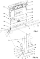
- 1a , 2 and 2a are perspective views of an assembly device 2 shown.
- the assembly device 2 comprises two supports 28 which are arranged at a distance from one another and which are connected to one another via at least one traverse 44 .
- a lower traverse, a middle traverse and an upper traverse are arranged.
- the lower crosshead is typically provided as a compression crosshead and the middle crosshead is typically provided as a tension crosshead.
- a toilet bowl, for example, can be stored on the pressure traverse and the tension traverse.
- a cistern 30 with corresponding actuating elements 31 is arranged between the middle cross member and the upper cross member in the variant shown.
- the assembly device 2 can also be used to store other sanitary elements.
- Each of the two supports 28 has a foot unit 1 .
- the mounting device 2 can be supported on a support structure 7 via the foot unit 1 .
- a profile element 32 is thereby provided for the support structure 7 .
- the profile element 32 has the shape of a U-profile.
- the support structure 7 can also be provided by a floor of a supporting structure, such as a building.
- the foot unit 1 comprises a connecting element 3 and a foot element 5 .
- the foot element 5 can be pivoted relative to the connecting element 3 .
- the connecting element 3 is connected to the support 28 or is provided by the support 28 .
- the foot element 5 can be pivoted from a first position into a second position relative to the stationary connecting element 3 or relative to the respective support 28 .
- the foot element 5 is shown in the first position and in the Figures 2 and 2a the foot element 5 is shown in the second position.
- a wider profile element 32 used than in the Figures 2 and 2a As shown by the figures, in the variant according to the Figures 1 and 1a a wider profile element 32 used than in the Figures 2 and 2a .
- the pivotability of the foot element 5 means that the foot unit 1 can be adapted to the conditions specified by the support structure 7 .
- the front surfaces 33 of the two supports 28 span a front plane.
- a paneling arrangement can be arranged on this front plane or on the front surfaces 33 .
- the foot elements 5 can be swiveled in such a way that the foot elements 5 do not penetrate the front plane or extend beyond the two front surfaces 33 either in the first position or in the second position. In this way it can be achieved that there is no collision between the foot elements 5 and planking.
- the pivot axis is such that the side surfaces of the foot element 5 are flush with an outer side surface 45 of the support in the first and the second position.
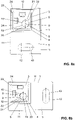
- FIGS 3 to 5b show a first embodiment of the foot unit 1 according to the present invention
- the Figures 6 to 8b show a second embodiment of the foot unit 1 according to the present invention. Based on Figures 3 to 8b the foot unit 1 will now be explained in detail. In the two embodiments, the same parts are provided with the same reference numbers and reference is made to the respective description.
- the foot unit 1 comprises a connecting element 3 with a connecting section 4 for connecting the foot unit 1 to the mounting device 2 and a foot element 5 with a bearing surface 6, with which the foot element 5 can be supported on the carrier structure 7.
- the bearing surface 6 extends horizontally in the installed position.
- the connecting element 3 and the foot element 5 are connected to one another via a swivel joint 8 .
- the foot element 5 can be pivoted relative to the connecting element 3 from the first position into the second position and from the second position back into the first position via the pivot joint 8 .
- the swivel joint 8 comprises a swivel section 9 on the foot element side and a swivel section 10 on the connecting element side.
- the two swivel sections 9, 10 are connected to one another.
- the pivoting sections 9, 10 can be pivoted relative to one another.
- the foot element 5 can be pivoted about a pivot axis S relative to the stationary connecting element 3 via the pivot joint 8 .
- the pivot axis S is essentially at right angles to the support surface 6 and runs essentially parallel to the central axis M of the supports 28. Viewed in the installed position, the pivot axis S runs in the vertical.
- pivoting angle between the first position and the second position is 90° in the embodiment shown.
- Other Pivot angles are also conceivable.
- the foot element 5 is designed as a foot plate.
- the foot element 5 has a first pair of side surfaces 11 and a second pair of side surfaces 12 .
- the side faces 11 of one pair are parallel and spaced from each other and the side faces 12 of the other pair are also parallel and spaced from each other.
- the side surfaces 11 and the side surfaces 12 are each at a right angle to one another.
- the side faces 11, 12 extend at right angles to the bearing surface 6 with respect to the bearing surface 6.
- the foot element 5 has an upper side 34 on the upper side.
- the pivoting section 9 on the side of the foot element is arranged on the upper side 34 in each case.
- the foot element 5 has the shape of a rectangle when viewed from above.
- the side surfaces 11 are the side surfaces of the broad side of the rectangle and the side surfaces 12 are the side surfaces of the narrow side of the rectangle. In other variants, it would also be conceivable for the side faces to be at a different angle to one another.
- the pivot axis S is centered between the two side surfaces 11 and laterally offset from the center between the two side surfaces 12. In other words, the pivot axis S is offset from the center of the footplate.
- the swivel joint 8 has a first stop 13 and a second stop 14 .
- the first stop 13 and the second stop 14 each provide a stop for the foot element 5 in the first or second position. This means that the foot element 5 can be pivoted between the two stops 13 , 14 .
- each of the stops 13, 14 has a stop section on the foot element side and a stop section on the connecting element side.
- the pivot joint 8 is provided by a cylinder pin 15 and a cylinder hole 17 .
- the pivoting section 9 on the foot element side is designed as a cylinder pin 15 and the pivoting section 10 on the connecting element side is designed as a cylinder opening 17 .
- the cylinder pin 15 has an outer surface 16 extending around the pivot axis S.
- the cylinder opening 17 has a pivot axis S extending around Inner surface 18 on. The outer surface 16 slides further pivoting movement relative to the inner surface 18 .
- the connecting section 4 is provided by a hollow profile 23 .
- An insert element 36 is mounted in the hollow profile 23, in which the pivoting section 10 on the connecting element side is formed.
- the insert element 36 is fixed here via a screw 37 on the hollow profile 23 .
- Said swivel joint 8 is inside the hollow profile 23.
- the insert element 36 comprises the stop section of the two stops on the connecting element side.
- a recess 38 extends from the side of the insert element 36 to the cylinder opening 17.
- the recess 38 is essentially used for easy installation of the insert element 36 on the pivoting section 9 on the foot element side.
- a flange section 39 extends from the Outer surface 16 away. This flange section 39 engages in a correspondingly designed recess 40 which extends laterally to the cylinder opening 17 . The engagement between the flange section 39 and the recess 40 means that the foot element 5 and the connecting element 3 cannot separate in the direction of the pivot axis S in the connected state.
- the pivot joint 8 is provided by an outer ball 19 having a partially spherical outer surface 20 and an inner ball 21 having a partially spherical inner surface 22 .
- the outer surface 20 is in contact with the inner surface 22 and during the pivoting movement the outer surface 20 and the inner surface 21 slide relative to one another.
- the outer sphere 19 is formed with incisions 41 .
- the incisions 41 allow the outer sphere 19 to snap over the inner sphere 21 during assembly.
- the stops 13 , 14 are provided by a comb 42 which is arranged on the outer sphere 19 and by correspondingly designed stop structures in the inner sphere 21 .
- the swivel joint 8 also has a latching structure 25.
- the latching structure 25 is arranged in such a way that when the first position is reached and/or when the second position is reached, a latching between the foot element 5 and the connecting element 3 provided.
- the locking structure is designed as a locking element 26 which is arranged on the connecting element 3 and as a corresponding locking recess 27 which is arranged on the foot element 5 .
- the latching element 26 engages in the latching recess 27 .
- the latching element 26 is preferably spring-loaded and engages in the latching recess 27 which is arranged on the outside of the flange section 39 .
- the connecting section 4 is provided by a hollow profile 23 in the embodiment shown.
- the hollow profile 23 protrudes from below into the respective support 28 and is connected to the support 28 there.
- the foot unit 1 can be arranged at different heights. It will be on the Figures 1 to 2a referred.
- Said side surfaces 11, 12 are parallel to the outer sides of the hollow profile 23.
- Two side surfaces 11, 12 are particularly preferably arranged essentially flush with the outer side 29 of the supports 28 and at a distance from the thickness of the support profile to the outer side 24 of the hollow profile 23.
- the foot element 5 also has an opening 43 through which a screw can be passed for attachment to the support structure.
Landscapes
- Health & Medical Sciences (AREA)
- Life Sciences & Earth Sciences (AREA)
- Engineering & Computer Science (AREA)
- Hydrology & Water Resources (AREA)
- Public Health (AREA)
- Water Supply & Treatment (AREA)
- Toilet Supplies (AREA)
Abstract
ein Verbindungselement (3) mit einem Verbindungsabschnitt (4) zur Verbindung der Fusseinheit (1) mit der Montagevorrichtung (2) und
ein Fusselement (5) mit einer Auflagefläche (6), mit weicher das Fusselement (5) auf einer Trägerstruktur (7) abstützbar ist,
wobei das Verbindungselement (3) und das Fusselement (5) über ein Schwenkgelenk (8) miteinander in Verbindung stehen,
wobei das Schwenkgelenk (8) ein fusselementseitiger Schwenkabschnitt (9) und ein verbindungselementseitiger Schwenkabschnitt (10) aufweist, welche Schwenkabschnitte (9, 10) jeweils verschwenkbar miteinander im Eingriff stehen, und
wobei das Fusselement (5) über das Schwenkgelenk (8) um eine Schwenkachse (S) relativ zum feststehenden Verbindungselement (3) zwischen einer ersten Lage und einer zweite Lage verschwenkbar ist.
Description
- Die vorliegende Erfindung betrifft eine Fusseinheit für eine sanitäre Montagevorrichtung für die Befestigung von mindestens einem Sanitärartikel nach Anspruch 1 sowie eine Montagevorrichtung nach Anspruch 11.
- Aus dem Stand der Technik sind Montagevorrichtungen zur Befestigung von Sanitärartikeln bekannt. Derartige Montagevorrichtungen werden hinter einer Vorwand fest installiert und dienen der Lagerung von Sanitärartikeln, wie Spülkästen, Toilettenschüsseln, Urinale, Armaturen, Waschbacken, Steuerungselemente, Elektroelemente etc. Beispielsweise offenbart die
EP 2 662 502 eine solche Montagevorrichtung. - Von der
EP 1 659 229 ist eine Montagevorrichtung mit einer Fussstütze bekannt geworden. Die Fussstütze ist dabei in je 90° versetzten Stellungen in ein Hohlprofil einsetzbar ist. Hierbei muss die gesamte Fussstütze aus dem Hohlprofil herausgezogen und wieder eingesetzt werden. Gerade bei engen Platzverhältnissen ist die Ausrichtung der Fussstützen sehr mühselig und kompliziert. - Obwohl mit den Montagevorrichtungen aus dem Stand der Technik bei der Montage in einem Gebäude sehr gute Resultate erzielt werden, ist es herstellerseitig wünschenswert die Herstellung zu vereinfachen. Viele der bekannten Montagevorrichtungen sind in der Herstellung sehr aufwändig.
- Ausgehend von diesem Stand der Technik liegt der Erfindung eine Aufgabe zugrunde, eine Fusseinheit für eine sanitäre Montagevorrichtung anzugeben, welche die Nachteile des Standes der Technik überwindet. Insbesondere ist es eine Aufgabe der vorliegenden Erfindung, Fusseinheit für eine sanitäre Montagevorrichtung anzugeben, welche einfacher an vorgegebene Strukturen anpassbar ist.
- Diese Aufgabe wird durch die Fusseinheit gemäss Anspruch 1 gelöst. Eine solche Fusseinheit ist für eine sanitäre Montagevorrichtung vorgesehen, welche ihrerseits der Lagerung von Sanitärelementen dient. Gemäss Anspruch 1 umfasst die Fusseinheit ein Verbindungselement mit einem Verbindungsabschnitt zur Verbindung der Fusseinheit mit der Montagevorrichtung und ein Fusselement mit einer Auflagefläche, mit welcher das Fusselement auf einer Trägerstruktur abstützbar ist. Das Verbindungselement und das Fusselement stehen über ein Schwenkgelenk miteinander in Verbindung. Das Schwenkgelenk weist ein fusselementseitiger Schwenkabschnitt und ein verbindungselementseitiger Schwenkabschnitt auf, welche Schwenkabschnitte jeweils verschwenkbar miteinander im Eingriff stehen. Das Fusselement ist über das Schwenkgelenk um eine Schwenkachse relativ zum feststehenden Verbindungselement zwischen einer ersten Lage und einer zweite Lage verschwenkbar.
- Durch die Anordnung des Schwenkgelenks wird die Möglichkeit einer einfachen Anpassung des Fusselements an vorgegebene Strukturen erlaubt. Das heisst, das Verschwenken der Fussstütze erlaubt eine einfache Anpassung an bauseitis vorgegebene Strukturen. Durch das einfache Verschwenken kann erreicht werden, dass bei einer allfälligen Kollision des Fusselements mit fest vorgegebenen Strukturen, beispielsweise von der Trägerstruktur ausgewichen werden kann, indem das Fusselement entsprechend verschwenkt wird. Auch kann das Fusselement durch die Verschwenkung an verschiedene Trägerstrukturen angepasst werden.
- Die Trägerstruktur ist beispielsweise eine Profilschiene oder der Boden eines Gebäudes.
- Vorzugsweise ist das Schwenkgelenk so ausgebildet, dass die Verstellung werkzeuglos erfolgen kann. Das heisst, die Verschwenkung kann von Hand, ohne Zuhilfenahme eines Werkzeuges bewerkstelligt werden.
- Die Schwenkachse ist im Wesentlichen rechtwinklig zur besagten Auflagefläche orientiert. In Einbaulage gesehen verläuft die Schwenkachse im Wesentlichen in der Vertikalen. Vorzugsweise ist der Schwenkwinkel zwischen der ersten Lage und der zweiten Lage zwischen 45° und 360° ist. Besonders bevorzugt ist der Schwenkwinkel 90° oder ein vielfaches von 90°.
- Vorzugsweise weist das Fusselement ein erstes Paar von Seitenflächen und ein zweites Paar von Seitenflächen aufweist, wobei bei jedem Paar von Seitenflächen die beiden Seitenflächen jeweils parallel und beabstandet zueinander liegen.
- Die Schwenkachse liegt in einer ersten Variante jeweils seitlich versetzt zur Mitte zwischen den beiden Seitenflächen liegt.
- In einer zweiten Variante liegt die Schwenkachse seitlich versetzt zur Mitte zwischen zwei gegenüberliegenden Seitenflächen und mittig zwischen den anderen beiden gegenüberliegenden Seitenflächen.
- Die Seitenflächen können auch als Anschlagsflächen bezeichnet werden. Beispielsweise können die Seitenflächen an Seitenwänden eines Profils oder an der Wand eines Gebäudes anschlagen.
- Die besagten Seitenflächen erstrecken sich von der Auflagefläche her gesehen rechtwinklig zur Auflagefläche weg. Gegenüber der Auflagefläche weist das Fusselement eine Oberseite auf, wo der fusselementseitige Schwenkabschnitt angeordnet ist. Mit anderen Worten gesagt ist das Fusselement plattenartig ausgebildet.
- Vorzugsweise weist das Schwenkgelenk einen ersten Anschlag und einen weiteren Anschlag auf, wobei das Fusselement zwischen den beiden Anschlägen verschwenkbar ist. Das Fusselement liegt in der besagten ersten Lage, wenn das Fusselement am ersten Anschlag anschlägt und in der besagten zweiten Lage, wenn das Fusselement am zweiten Anschlag anschlägt. Die beiden Anschläge liegen dabei derart, dass der oben beschriebene Verschwenkwinkel erreicht werden kann.
- Vorzugsweise werden die besagten Anschläge jeweils mit einem fusselementseitigen Anschlagsabschnitt und einem verbindungselementseitigen Anschlagsabschnitt bereitgestellt. Die beiden Anschlagsabschnitte bilden jeweils den Anschlag.
- In ersten Ausführungsform wird das Schwenkgelenk durch einen Zylinderzapfen mit einer kreiszylindrischen sich um die Schwenkachse herumerstrecken Aussenfläche und eine Zylinderöffnung mit einer kreiszylindrischen sich um die Schwenkachse herumerstrecken Innenfläche bereitgestellt, wobei die Aussenfläche mit der Innenfläche in Kontakt ist und wobei bei der Schwenkbewegung die Aussenfläche und die Innenfläche relativ zueinander gleiten.
- Wenn der Zylinderzapfen der fusselementseitige Schwenkabschnitt ist, ist die Zylinderöffnung der verbindungselementseitige Schwenkabschnitt. Wenn der Zylinderzapfen der verbindungselementseitige Schwenkabschnitt ist, ist die Zylinderöffnung der fusselementseitige Schwenkabschnitt.
- In einer zweiten Ausführungsform wird das Schwenkgelenk durch eine Aussenkugel mit einer teilweise kugelförmigen Aussenfläche und eine Innenkugel mit einer teilweise kugelförmigen Innenfläche bereitgestellt, wobei die Aussenfläche mit der Innenfläche in Kontakt ist und wobei bei der Schwenkbewegung die Aussenfläche und die Innenfläche relativ zueinander gleiten.
- Wenn die Aussenkugel der fusselementseitige Schwenkabschnitt ist, ist die Innenkugel der verbindungselementseitige Schwenkabschnitt. Wenn die Aussenkugel der verbindungselementseitige Schwenkabschnitt ist, ist die Innenkugel der fusselementseitige Schwenkabschnitt.
- Vorzugsweise wird der Verbindungsabschnitt durch ein Hohlprofil bereitgestellt, welches mit der sanitären Montagevorrichtung verbindbar ist; oder welches durch die sanitäre Montagevorrichtung bereitgestellt wird.
- Vorzugsweise weist das Hohlprofil einen quadratischen Querschnitt auf und die Schwenkachse verläuft parallel und seitlich versetzt zur Mittelachse des Hohlprofils verläuft.
- Vorzugsweise verlaufen die Seitenflächen der Fusseinheit in der ersten Lage und der zweiten Lage parallel zu den Seitenflächen des Hohlprofils.
- Vorzugsweise ist das Hohlprofil in einer Ecke von zwei Seitenflächen angeordnet und steht in einem Abstand von 0 bis 5 Millimeter von den beiden Seitenflächen entfernt.
- Vorzugsweise weist das Schwenkgelenk eine Raststruktur auf, welche bei Erreichen der ersten Lage und/oder bei Erreichen der zweiten Lage eine Verrastung zwischen dem Fusselement und dem Verbindungselement bereitstellt.
- Hierdurch kann dem Installateur eine haptische Rückmeldung bei Erreichen der ersten oder der zweiten Lage gegeben werden. Weiter wird das Fusselement in der ersten oder der zweiten Lage gehalten.
- Vorzugsweise umfasst das Fussteil eine Durchgangsöffnung zur Durchführung einer Befestigungsschraube.
- Eine Montagevorrichtung für die Befestigung von mindestens einem Sanitärartikel, umfasst zwei beabstandet zueinander verlaufende und als Hohlprofile ausgebildete Stützen, welche sich jeweils entlang einer Mittelachse erstrecken, und mindestens eine Traverse, welche fest mit den Stützen in Verbindung steht und die Stützen miteinander verbindet, und wobei pro Stütze je eine Fusseinheit nach obiger Beschreibung angeordnet ist.
- Vorzugsweise steht die Fusseinheit mit dem Verbindungsabschnitt mit der jeweiligen Stütze in Verbindung. Die Stütze selbst kann aber auch den Verbindungsabschnitt bereitstellen.
- Vorzugsweise steht die Schwenkachse derart zur Stütze, dass mindestens zwei aneinander anschliessende Seitenflächen sowohl in der ersten Lage wie auch in der zweiten Lage bündig mit mindestens einer Aussenseite der Stütze sind oder im Wesentlichen bündig mit mindestens einer Aussenseite der Stütze sind.
- Vorzugsweise spannen die Stützen mit ihren Frontflächen eine Frontebene auf, auf welcher eine Beplankungsanordnung anordbar ist. Die Schwenkachse steht derart zur Stütze, dass das Fusselement sowohl in der ersten Lage wie auch in der zweiten Lage die Frontebene nicht durchdringen. Das Fusselement erstreckt sich demnach nicht durch die Frontebene hindurch. Das heisst, das Fusselement liegt bezüglich der Beplankungsanordnung in jeder Lage hinter der Frontebene. Insofern kommt es zu keiner Kollision der Beplankungsanordnung mit dem Fusselement.
- Vorzugsweise weisen die Stützen jeweils eine aussenseitig liegende Seitenfläche auf, wobei die die Schwenkachse derart zur Stütze steht, dass das Fusselement sowohl in der ersten Lage wie auch in der zweiten Lage bündig oder im Wesentlichen bündig mit der besagten Seitenfläche ist. Die aussenseitig liegende Seitenfläche liegt auf der Aussenseite der Stütze, also auf der Seite, welche der anderen Stütze abgewandt ist.
- Vorzugsweise ist das Verbindungselement und der Verbindungsabschnitt integraler Bestandteil der Stütze. Alternativerweise ragt die Fusseinheit mit dem Verbindungsabschnitt in die Stütze ein.
- Vorzugsweise weist die Stütze einen quadratischen Querschnitt auf und die Schwenkachse verläuft parallel und seitlich versetzt zur Mittelachse der Stütze.
- Weitere Ausführungsformen sind in den abhängigen Ansprüchen angegeben.
- Bevorzugte Ausführungsformen der Erfindung werden im Folgenden anhand der Zeichnungen beschrieben, die lediglich zur Erläuterung dienen und nicht einschränkend auszulegen sind. In den Zeichnungen zeigen:
- Fig. 1
- eine perspektivische Ansicht einer Montagevorrichtung mit Fusseinheiten, wobei die Fusselemente der Fusseinheiten in einer ersten Lage stehen,
- Fig. 1a
- eine Detailansicht der
Figur 1 , - Fig. 2
- eine perspektivische Ansicht einer Montagevorrichtung mit Fusseinheiten, wobei die Fusselemente der Fusseinheiten in einer zweiten Lage stehen,
- Fig. 2a
- eine Detailansicht der
Figur 2 , - Fig. 3
- eine Explosionsdarstellung einer ersten Ausführungsform einer Fusseinheit,
- Fig. 4
- eine weitere Explosionsdarstellung der Fusseinheit nach
Fig. 3 ; - Fig. 5a
- eine Draufsicht auf die Fusseinheit der
Figuren 3 und 4 in einer ersten Lage; - Fig. 5b
- eine Draufsicht auf die Fusseinheit der
Figuren 3 und 4 in einer zweiten Lage; - Fig. 6
- eine Explosionsdarstellung einer zweiten Ausführungsform einer Fusseinheit,
- Fig. 7
- eine weitere Explosionsdarstellung der Fusseinheit nach
Fig. 6 ; - Fig. 8a
- eine Draufsicht auf die Fusseinheit der
Figuren 6 und 7 in einer ersten Lage; und - Fig. 8b
- eine Draufsicht auf die Fusseinheit der
Figuren 6 und 7 in einer zweiten Lage. - In den
Figuren 1, 1a ,2 und 2a werden perspektivische Ansichten einer Montagevorrichtung 2 gezeigt. Die Montagevorrichtung 2 umfasst in der gezeigten Ausführungsform zwei beanstandet zueinander angeordnete Stützen 28, welche über mindestens eine Traverse 44 miteinander verbunden sind. In der gezeigten Ausführungsform ist eine untere Traverse, eine mittlere Traverse und eine obere Traverse angeordnet. Die untere Traverse wird typischerweise als Drucktraverse und die mittlere Traverse wird typischerweise als Zugtraverse bereitgestellt. An der Drucktraverse und der Zugtraverse ist beispielsweise eine Toilettenschüssel lagerbar. Weiter ist zwischen der mittleren Traverse und der oberen Traverse in der gezeigten Variante ein Spülkasten 30 mit entsprechenden Betätigungselementen 31 angeordnet. Die Montagevorrichtung 2 kann auch der Lagerung von anderen Sanitärelementen dienen. - Jede der beiden Stützen 28 weist eine Fusseinheit 1 auf. Über die Fusseinheit 1 ist die Montagevorrichtung 2 an einer Trägerstruktur 7 abstützbar. Die Trägerstruktur 7 wird hierdurch ein Profilelement 32 bereitgestellt. Das Profilelement 32 weist in der gezeigten Ausführungsform die Form eines U-Profils auf. Die Trägerstruktur 7 kann aber auch durch einen Boden eines Tragwerks, wie beispielsweise einem Gebäude, bereitgestellt werden.
- Die Fusseinheit 1 umfasst gemäss der in den Figuren gezeigten Ausführungsform ein Verbindungselement 3 und ein Fusselement 5. Das Fusselement 5 ist dabei verschwenkbar zum Verbindungselement 3 angeordnet. Das Verbindungselement 3 steht mit der Stütze 28 in Verbindung oder wird durch die Stütze 28 bereitgestellt. Das Fusselement 5 ist von einer ersten Lage in eine zweite Lage relativ zum feststehenden Verbindungselement 3 bzw. relativ zu der jeweiligen Stütze 28 verschwenkbar. I
- In den
Figuren 1 und 1a wird das Fusselement 5 in der ersten Lage gezeigt und in denFiguren 2 und 2a wird das Fusselement 5 in der zweiten Lage gezeigt. Wie von den Figuren gezeigt wird, wird in der Variante gemäss denFiguren 1 und 1a ein breiteres Profilelement 32 eingesetzt als in denFiguren 2 und 2a . Durch die Verschwenkbarkeit des Fusselements 5 kann die Fusseinheit 1 an die durch die Trägerstruktur 7 vorgegebenen Gegebenheiten angepasst werden. - Die Frontflächen 33 der beiden Stützen 28 spannen eine Frontebene auf. Auf dieser Frontebene bzw. auf den Frontflächen 33 ist eine Beplankungsanordnung anordbar. Die Fusselemente 5 sind dabei derart schwenkbar, dass die Fusselemente 5 sowohl in der ersten Lage wie auch in der zweiten Lage die Frontebene nicht durchdringen bzw. sich nicht über die beiden Frontflächen 33 weg erstrecken. Hierdurch kann erreicht werden, dass es zu keiner Kollision zwischen den Fusselementen 5 und einer Beplankung kommt. Von den
Figuren 1, 1a und2, 2a ist weiter ersichtlich, dass die Schwenkachse derart liegt, dass die Seitenflächen des Fusselements 5 in der ersten und der zweiten Lage jeweils bündig mit einer äusseren Seitenfläche 45 der Stütze liegen. - Die
Figuren 3 bis 5b zeigen eine erste Ausführungsform der Fusseinheit 1 gemäss der vorliegenden Erfindung und dieFiguren 6 bis 8b zeigen eine zweite Ausführungsform der Fusseinheit 1 gemäss der vorliegenden Erfindung. Anhand derFiguren 3 bis 8b wird nun die Fusseinheit 1 detailliert erläutert. Bei den beiden Ausführungsformen sind gleiche Teile mit gleichen Bezugszeichen versehen und es wird auf die jeweilige Beschreibung verwiesen. - Die Fusseinheit 1 umfasst, wie bereits erwähnt, ein Verbindungselement 3 mit einem Verbindungsabschnitt 4 zur Verbindung der Fusseinheit 1 mit der Montagevorrichtung 2 und ein Fusselement 5 mit einer Auflagefläche 6, mit welcher das Fusselement 5 auf der Trägerstruktur 7 abstützbar ist. Die Auflagefläche 6 erstreckt sich in Einbaulage in der Horizontalen.
- Bei beiden Ausführungsformen stehen das Verbindungselement 3 und das Fusselement 5 über ein Schwenkgelenk 8 miteinander in Verbindung. Über das Schwenkgelenk 8 lässt sich das Fusselement 5 relativ zum Verbindungselement 3 von der ersten Lage in die zweite Lage und von der zweiten Lage zurück in die erste Lage verschwenken.
- Das Schwenkgelenk 8 umfasst jeweils ein fusselementseitiger Schwenkabschnitt 9 und ein verbindungselementseitiger Schwenkabschnitt 10. Die beiden Schwenkabschnitte 9, 10 stehen dabei in Verbindung miteinander. Die Schwenkabschnitte 9, 10 sind relativ zueinander verschwenkbar.
- Das Fusselement 5 ist über das Schwenkgelenk 8 um eine Schwenkachse S relativ zum feststehenden Verbindungselement 3 verschwenkbar. Die Schwenkachse S steht im Wesentlichen rechtwinklig zur Auflagefläche 6 und verläuft im Wesentlichen parallel zur Mittelachse M der Stützen 28. In Einbaulage gesehen verläuft die Schwenkachse S in der Vertikalen.
- Von den
Figuren 1 bis 2a wird ersichtlich, dass der Schwenkwinkel zwischen der ersten Lage und der zweiten Lage in der gezeigten Ausführungsform 90° ist. Andere Schwenkwinkel sind ebenfalls denkbar. - Das Fusselement 5 ist als Fussplatte ausgebildet. Das Fusselement 5 weist dabei ein erstes Paar von Seitenflächen 11 und ein zweites Paar von Seitenflächen 12 auf. Die Seitenflächen 11 des einen Paars verlaufen parallel und beanstandet zueinander und die Seitenflächen 12 des anderen Paars verlaufen ebenfalls parallel und beanstandet zueinander. Die Seitenflächen 11 und die Seitenflächen 12 stehen in der gezeigten Ausführungsform jeweils in einem rechten Winkel zueinander. Die Seitenflächen 11, 12 erstrecken sich bezüglich der Auflagefläche 6 rechtwinklig zur Auflagefläche 6. Oberseitig weist das Fusselement 5 eine Oberseite 34 auf. Auf der Oberseite 34 ist jeweils der fusselementseitige Schwenkabschnitt 9 angeordnet. Das Fusselement 5 weist von oben her gesehen die Form eines Rechtecks auf. Die Seitenflächen 11 sind dabei die Seitenflächen der Breitseite des Rechtecks und die Seitenflächen 12 sind die Seitenflächen der Schmalseite des Rechtecks. In anderen Varianten wäre es auch denkbar, dass die Seitenflächen in einem anderen Winkel zueinander stehen.
- In der gezeigten Ausführungsform steht die Schwenkachse S mittig zwischen den beiden Seitenflächen 11 und seitlich versetzt zur Mitte zwischen den beiden Seitenflächen 12. Mit anderen Worten gesagt steht die Schwenkachse S versetzt zur Mitte der Fussplatte.
- In der gezeigten Ausführungsform weist das Schwenkgelenk 8 einen ersten Anschlag 13 und einen zweiten Anschlag 14 auf. Der erste Anschlag 13 und der zweite Anschlag 14 stellen jeweils einen Anschlag für das Fusselement 5 in der ersten bzw. der zweiten Lage bereit. Das heisst, dass das Fusselement 5 zwischen den beiden Anschlägen 13, 14 verschwenkbar ist.
- In der gezeigten Ausführungsform weist jeder der Anschläge 13, 14 jeweils ein fusselementseitiger Anschlagsabschnitt und jeweils ein verbindungselementseitiger Anschlagsabschnitt auf.
- In der ersten Ausführungsform wird das Schwenkgelenk 8 durch einen Zylinderzapfen 15 und durch eine Zylinderöffnung 17 bereitgestellt. Dabei ist der fusselementseitige Schwenkabschnitt 9 als Zylinderzapfen 15 und der verbindungselementseitige Schwenkabschnitt 10 als Zylinderöffnung 17 ausgebildet. Der Zylinderzapfen 15 weist eine sich um die Schwenkachse S herum erstreckende Aussenfläche 16 auf. Die Zylinderöffnung 17 weist eine sich um die Schwenkachse S herum erstreckende Innenfläche 18 auf. Weitere Schwenkbewegung gleitet die Aussenfläche 16 relativ zur Innenfläche 18. In der gezeigten Ausführungsform erstreckt sich der fusselementseitige Anschlagsabschnitt als Nocke 35 von der Aussenfläche 16 weg.
- In beiden Ausführungsformen wird der Verbindungsabschnitt 4 durch ein Hohlprofil 23 bereitgestellt. Im Hohlprofil 23 ist ein Einsatzelement 36 gelagert, in welchem der verbindungselementseitige Schwenkabschnitt 10 ausgebildet ist. Das Einsatzelement 36 wird hier über eine Schraube 37 am Hohlprofil 23 fest gelagert. Das besagte Schwenkgelenk 8 liegt im Inneren des Hohlprofils 23.
- Weiter umfasst das Einsatzelement 36 den verbindungselementseitigen Anschlagsabschnitt der beiden Anschläge.
- In der ersten Ausführungsform erstreckt sich von der Seite des Einsatzelements 36 eine Ausnehmung 38 bis hin zur Zylinderöffnung 17. Die Ausnehmung 38 dient im Wesentlichen der einfachen Montage des Einsatzelementes 36 auf dem fusselementseitigen Schwenkabschnitt 9. In der gezeigten Ausführungsform erstreckt sich ein Flanschabschnitt 39 von der Aussenfläche 16 weg. Dieser Flanschabschnitt 39 greift in eine entsprechend ausgebildete Ausnehmung 40, die sich seitlich zur Zylinderöffnung 17 erstreckt. Über den Eingriff zwischen Flanschabschnitt 39 und Ausnehmung 40 wird erreicht, dass es sich das Fusselement 5 und das Verbindungselement 3 in Richtung der Schwenkachse S im verbunden Zustand nicht trennen können.
- In der zweiten Ausführungsform wird das Schwenkgelenk 8 durch eine Aussenkugel 19 mit einer teilweise kugelförmigen Aussenfläche 20 und eine Innenkugel 21 mit einer teilweise kugelförmigen Innenfläche 22 bereitgestellt. Die Aussenfläche 20 ist dabei mit der Innenfläche 22 in Kontakt und bei der Schwenkbewegung gleiten die Aussenfläche 20 und die Innenfläche 21 relativ zueinander. Die Aussenkugel 19 ist mit Einschnitten 41 ausgebildet. Die Einschnitte 41 erlauben ein Überschnappen der Aussenkugel 19 über die Innenkugel 21 bei der Montage. Die Anschläge 13, 14 werden in der gezeigten Ausführungsform durch einen Kamm 42, der auf der Aussenkugel 19 angeordnet ist, und durch entsprechend ausgebildete Anschlagsstrukturen in der Innenkugel 21 bereitgestellt.
- Weiter weist das Schwenkgelenk 8 eine Raststruktur 25. Die Raststruktur 25 ist dabei derart angeordnet, dass bei Erreichen der ersten Lage und oder bei Erreichen der zweiten Lage eine Verrastung zwischen dem Fusselement 5 und dem Verbindungselement 3 bereitgestellt wird.
- In der ersten Ausführungsform ist die Raststruktur als Rastelement 26, welches am Verbindungselement 3 angeordnet ist und als korrespondierende Rastausnehmung 27, die am Fusselement 5 angeordnet ist, ausgebildet. Das Rastelement 26 greift dabei in die Rastausnehmung 27 ein. Vorzugsweise ist das Rastelement 26 gefedert ausgebildet und greift in die Rastausnehmung 27 ein, die aussenseitig am Flanschabschnitt 39 angeordnet ist.
- Wie oben erwähnt ist der Verbindungsabschnitt 4 in der gezeigten Ausführungsform durch ein Hohlprofil 23 bereitgestellt. Das Hohlprofil 23 ragt dabei von unten her in die jeweilige Stütze 28 ein und wird dort mit der Stütze 28 verbunden. Die Fusseinheit 1 kann auf verschiedenen Höhen angeordnet werden. Es wird auf die
Figuren 1 bis 2a verwiesen. Die besagten Seitenflächen 11, 12 sind dabei parallel zu den Aussenseiten des Hohlprofils 23. Besonders bevorzugt sind zwei Seitenflächen 11, 12 im Wesentlichen bündig zur Aussenseite 29 der Stützen 28 und mit einem Abstand von der Dicke des Stützenprofils zur Aussenseite 24 des Hohlprofils 23 angeordnet. - Das Fusselement 5 weist weiterhin einen Durchbruch 43 auf, durch welchen eine Schraube zur Befestigung an die Trägerstruktur hindurchgeführt werden kann.
BEZUGSZEICHENLISTE 1 Fusseinheit 30 Spülkasten 2 sanitäre Montagevorrichtung 31 Betätigungselemente 3 Verbindungselement 32 Profilelement 4 Verbindungsabschnitt 33 Frontfläche 5 Fusselement 34 Oberseite 6 Auflagefläche 35 Nocke 7 Trägerstruktur 36 Einsatzelement 8 Schwenkgelenk 37 Schraube 9 fusselementseitiger 38 Ausnehmung Schwenkabschnitt 39 Flanschabschnitt 10 verbindungselementseitiger Schwenkabschnitt 40 Ausnehmung 41 Einschnitt 11 seitliche Seitenflächen vom ersten Paar 42 Kamm 43 Durchbruch 12 seitliche Anschlagsfläche vom zweiten Paar 44 Traverse 45 äussere Seitenfläche 13 erster Anschlag 14 weiterer Anschlag S Schwenkachse 15 Zylinderzapfen M Mittelachse 16 Aussenfläche 17 Zylinderöffnung 18 Innenfläche 19 Aussenkugel 20 kugelförmige Aussenfläche 21 Innenkugel 22 Innenfläche 23 Hohlprofil 24 Seitenflächen 25 Raststruktur 26 Rastlasche 27 Rastausnehmung 28 Stütze 29 Aussenseite
Claims (16)
- Fusseinheit (1) für eine sanitäre Montagevorrichtung (2) umfassend
ein Verbindungselement (3) mit einem Verbindungsabschnitt (4) zur Verbindung der Fusseinheit (1) mit der Montagevorrichtung (2) und
ein Fusselement (5) mit einer Auflagefläche (6), mit welcher das Fusselement (5) auf einer Trägerstruktur (7) abstützbar ist,
wobei das Verbindungselement (3) und das Fusselement (5) über ein Schwenkgelenk (8) miteinander in Verbindung stehen,
wobei das Schwenkgelenk (8) ein fusselementseitiger Schwenkabschnitt (9) und ein verbindungselementseitiger Schwenkabschnitt (10) aufweist, welche Schwenkabschnitte (9, 10) jeweils verschwenkbar miteinander im Eingriff stehen, und
wobei das Fusselement (5) über das Schwenkgelenk (8) um eine Schwenkachse (S) relativ zum feststehenden Verbindungselement (3) zwischen einer ersten Lage und einer zweite Lage verschwenkbar ist. - Fusseinheit (1) nach Anspruch 1, dadurch gekennzeichnet, dass der Schwenkwinkel zwischen der ersten Lage und der zweiten Lage zwischen 45° und 360° ist, insbesondere dass der Schwenkwinkel 90° oder ein vielfaches von 90° ist.
- Fusseinheit (1) nach einem der vorhergehenden Ansprüche, dadurch gekennzeichnet, dass das Fusselement (5) ein erstes Paar von Seitenflächen (11) und ein zweites Paar von Seitenflächen (12) aufweist, wobei bei jedem Paar von Seitenflächen (11, 12) die beiden Seitenflächen (11, 12) jeweils parallel und beabstandet zueinander liegen,
wobei die Schwenkachse (S) jeweils seitlich versetzt zur Mitte zwischen den beiden Seitenflächen (11, 12) liegt, oder
wobei die Schwenkachse (S) seitlich versetzt zur Mitte zwischen zwei gegenüberliegenden Seitenflächen (11) und mittig zwischen den anderen beiden gegenüberliegenden Seitenflächen (12) liegt. - Fusseinheit (1) nach einem der vorhergehenden Ansprüche, dadurch gekennzeichnet, dass das Schwenkgelenk (8) einen ersten Anschlag (13) und einen weiteren Anschlag (14) aufweist, wobei das Fusselement zwischen den beiden Anschlägen (13, 14) verschwenkbar ist.
- Fusseinheit (1) nach einem der vorhergehenden Ansprüche, dadurch gekennzeichnet, dass das Schwenkgelenk (8) durch einen Zylinderzapfen (15) mit einer kreiszylindrischen sich um die Schwenkachse (S) herumerstrecken Aussenfläche (16) und eine Zylinderöffnung (17) mit einer kreiszylindrischen sich um die Schwenkachse (S) herumerstrecken Innenfläche (18) bereitgestellt ist, wobei die Aussenfläche (16) mit der Innenfläche (18) in Kontakt ist und wobei bei der Schwenkbewegung die Aussenfläche (16) und die Innenfläche (18) relativ zueinander gleiten.
- Fusseinheit (1) nach einem der vorhergehenden Ansprüche, dadurch gekennzeichnet, dass das Schwenkgelenk (8) durch eine Aussenkugel (19) mit einer teilweise kugelförmigen Aussenfläche (20) und eine Innenkugel (21) mit einer teilweise kugelförmigen Innenfläche (22) bereitgestellt ist, wobei die Aussenfläche (20) mit der Innenfläche (22) in Kontakt ist und wobei bei der Schwenkbewegung die Aussenfläche (20) und die Innenfläche (21) relativ zueinander gleiten.
- Fusseinheit (1) nach einem der vorhergehenden Ansprüche, dadurch gekennzeichnet, dass der Verbindungsabschnitt (4) durch ein Hohlprofil (23) bereitgestellt wird, welches mit der sanitären Montagevorrichtung (2) verbindbar ist, oder welches durch die sanitäre Montagevorrichtung (2) bereitgestellt wird.
- Fusseinheit (1) nach Anspruch 7, dadurch gekennzeichnet, dass das Hohlprofil (23) einen quadratischen Querschnitt aufweist und dass die Schwenkachse (S) parallel und seitlich versetzt zur Mittelachse (M) des Hohlprofils (23) verläuft.
- Fusseinheit (1) nach Anspruch 3 und einem der vorhergehenden Ansprüche 7 und 8, dadurch gekennzeichnet, dass die Seitenflächen (11, 12) der Fusseinheit (1) in der ersten Lage und der zweiten Lage parallel zu den Seitenflächen (24) des Hohlprofils (23) verlaufen.
- Fusseinheit (1) nach einem der vorhergehenden Ansprüche, dadurch gekennzeichnet, dass das Schwenkgelenk (8) eine Raststruktur (25, 26, 27) aufweist, welche bei Erreichen der ersten Lage und/oder bei Erreichen der zweiten Lage eine Verrastung zwischen dem Fusselement (5) und dem Verbindungselement (3) bereitstellt.
- Montagevorrichtung (2) für die Befestigung von mindestens einem Sanitärartikel, umfassend
zwei beabstandet zueinander verlaufende und als Hohlprofile ausgebildete Stützen (28), welche sich jeweils entlang einer Mittelachse (M) erstrecken, und
mindestens eine Traverse (44), welche fest mit den Stützen (28) in Verbindung steht und die Stützen (28) miteinander verbindet, und
pro Stütze (28) je eine Fusseinheit (1) nach einem der vorhergehenden Ansprüche angeordnet ist. - Montagevorrichtung (2) nach Anspruch 11, dadurch gekennzeichnet, dass die Schwenkachse (S) derart zur Stütze (28) steht, dass mindestens zwei aneinander anschliessende Seitenflächen (11, 12) sowohl in der ersten Lage wie auch in der zweiten Lage bündig mit mindestens einer Aussenseite (29) der Stütze (28) sind oder im Wesentlichen bündig mit mindestens einer Aussenseite (29) der Stütze (28) sind.
- Montagevorrichtung (2) nach Montagevorrichtung (1) nach Anspruch 11, dadurch gekennzeichnet, dass die Stützen (28) mit ihren Fronflächen (33) eine Frontebene aufspannen, auf weicher eine Beplankungsanordnung anordbar ist, und die Schwenkachse (S) derart zur Stütze (28) steht, dass das Fusselement sowohl in der ersten Lage wie auch in der zweiten Lage die Frontebene nicht durchdringen.
- Montagevorrichtung nach Anspruch 12 oder 13, dadurch gekennzeichnet, dass die Stützen jeweils eine aussenseitig liegende Seitenfläche (45) aufweisen, wobei die die Schwenkachse (S) derart zur Stütze (28) steht, dass das Fusselement sowohl in der ersten Lage wie auch in der zweiten Lage bündig oder im Wesentlichen bündig mit der besagten Seitenfläche (45) ist.
- Montagevorrichtung (2) nach einem der Ansprüche 11 bis 14, dadurch gekennzeichnet, dass das Verbindungselement (3) und der Verbindungsabschnitt (4) integraler Bestandteil der Stütze (28) ist; oder dass die Fusseinheit (1) mit dem Verbindungsabschnitt (4) in die Stütze (28) einragt.
- Montagevorrichtung (2) nach einem der Ansprüche 11 bis 15, dadurch gekennzeichnet, dass die Stütze (28) einen quadratischen Querschnitt aufweist und dass die Schwenkachse (S) parallel und seitlich versetzt zur Mittelachse (M) der Stütze verläuft.
Priority Applications (2)
| Application Number | Priority Date | Filing Date | Title |
|---|---|---|---|
| EP21156806.8A EP4043655B1 (de) | 2021-02-12 | 2021-02-12 | Fusseinheit und montagevorrichtung mit solch einer fusseinheit |
| CN202210070523.8A CN114922267A (zh) | 2021-02-12 | 2022-01-21 | 脚单元和安装装置 |
Applications Claiming Priority (1)
| Application Number | Priority Date | Filing Date | Title |
|---|---|---|---|
| EP21156806.8A EP4043655B1 (de) | 2021-02-12 | 2021-02-12 | Fusseinheit und montagevorrichtung mit solch einer fusseinheit |
Publications (2)
| Publication Number | Publication Date |
|---|---|
| EP4043655A1 true EP4043655A1 (de) | 2022-08-17 |
| EP4043655B1 EP4043655B1 (de) | 2024-06-05 |
Family
ID=74595136
Family Applications (1)
| Application Number | Title | Priority Date | Filing Date |
|---|---|---|---|
| EP21156806.8A Active EP4043655B1 (de) | 2021-02-12 | 2021-02-12 | Fusseinheit und montagevorrichtung mit solch einer fusseinheit |
Country Status (2)
| Country | Link |
|---|---|
| EP (1) | EP4043655B1 (de) |
| CN (1) | CN114922267A (de) |
Citations (7)
| Publication number | Priority date | Publication date | Assignee | Title |
|---|---|---|---|---|
| US2810917A (en) * | 1952-07-29 | 1957-10-29 | J A Zurn Mfg Co | Lavatory carrier |
| DE1803775A1 (de) * | 1967-10-26 | 1969-06-19 | Ankarsrums Bruk Ab | Stuezenvorrichtung fuer eine Badewanne |
| EP1659229A2 (de) | 2004-10-22 | 2006-05-24 | VIEGA GmbH & Co. KG. | Montagefuss und Sanitärelement |
| DE202006011801U1 (de) * | 2006-08-01 | 2006-09-28 | Mayr, Frank | Rahmenkonstruktion für die Montage eines Sanitärgegenstandes |
| EP2662502A1 (de) | 2012-05-09 | 2013-11-13 | Geberit International AG | Montagevorrichtung für die Befestigung eines Sanitärapparates |
| EP2740849A1 (de) * | 2011-09-21 | 2014-06-11 | Fominaya, S.A. | Einbaurahmen zur fixierung von toilettenelementen und herstellungsverfahren dafür |
| WO2020220059A1 (de) * | 2019-04-29 | 2020-11-05 | Christian Micheluzzi | Montagegestell zur montage einer bodenebenen duschtasse |
Family Cites Families (6)
| Publication number | Priority date | Publication date | Assignee | Title |
|---|---|---|---|---|
| DE19929497A1 (de) * | 1999-06-28 | 2001-01-04 | Correcta Gmbh | Mit einem Vorwandelement verbundener Wannenträger |
| JP4062914B2 (ja) * | 2001-12-14 | 2008-03-19 | Sus株式会社 | フットコネクタ |
| EP2789931B1 (de) * | 2013-04-12 | 2020-08-12 | Renusol Europe GmbH | Haltervorrichtung zum Befestigen eines Flächenmoduls an einem Träger |
| DE102014222325A1 (de) * | 2014-10-31 | 2016-05-04 | Hünnebeck GmbH | Höhenverstellbares Fußstück als Bestandteil eines Gerüsts sowie Gerüst mit einem solchen |
| EP3067477B1 (de) * | 2015-03-11 | 2019-05-08 | Raccords et Plastiques Nicoll | Befestigungssystem für stützrahmen, befestigungseinheit, die eine solche vorrichtung umfasst, und befestigungsverfahren auf einem stützrahmen |
| CN210151844U (zh) * | 2019-02-18 | 2020-03-17 | 厦门瑞尔特卫浴科技股份有限公司 | 一种隐藏式水箱的安装架及具有其的卫生设备 |
-
2021
- 2021-02-12 EP EP21156806.8A patent/EP4043655B1/de active Active
-
2022
- 2022-01-21 CN CN202210070523.8A patent/CN114922267A/zh active Pending
Patent Citations (7)
| Publication number | Priority date | Publication date | Assignee | Title |
|---|---|---|---|---|
| US2810917A (en) * | 1952-07-29 | 1957-10-29 | J A Zurn Mfg Co | Lavatory carrier |
| DE1803775A1 (de) * | 1967-10-26 | 1969-06-19 | Ankarsrums Bruk Ab | Stuezenvorrichtung fuer eine Badewanne |
| EP1659229A2 (de) | 2004-10-22 | 2006-05-24 | VIEGA GmbH & Co. KG. | Montagefuss und Sanitärelement |
| DE202006011801U1 (de) * | 2006-08-01 | 2006-09-28 | Mayr, Frank | Rahmenkonstruktion für die Montage eines Sanitärgegenstandes |
| EP2740849A1 (de) * | 2011-09-21 | 2014-06-11 | Fominaya, S.A. | Einbaurahmen zur fixierung von toilettenelementen und herstellungsverfahren dafür |
| EP2662502A1 (de) | 2012-05-09 | 2013-11-13 | Geberit International AG | Montagevorrichtung für die Befestigung eines Sanitärapparates |
| WO2020220059A1 (de) * | 2019-04-29 | 2020-11-05 | Christian Micheluzzi | Montagegestell zur montage einer bodenebenen duschtasse |
Also Published As
| Publication number | Publication date |
|---|---|
| EP4043655B1 (de) | 2024-06-05 |
| CN114922267A (zh) | 2022-08-19 |
Similar Documents
| Publication | Publication Date | Title |
|---|---|---|
| EP3746608B1 (de) | Befestigungssystem zur befestigung eines sanitärartikels | |
| EP3296474B1 (de) | Befestigungseinrichtung für ein wandhängendes sanitärobjekt und befestigungsanordnung | |
| EP3910118B1 (de) | Ablaufanordnung | |
| EP3569102A1 (de) | Befestigungssystem für einen waschtisch | |
| EP4043655B1 (de) | Fusseinheit und montagevorrichtung mit solch einer fusseinheit | |
| EP1812167B1 (de) | Strahlaustrittselement für sanitärarmaturen | |
| EP4230885B1 (de) | Wandanker | |
| EP4202132B1 (de) | Sanitäranordnung, wandanordnung umfassend eine solche sanitäranordnung und verfahren zur montage einer solchen wandanordnung | |
| EP4279674A1 (de) | Betätigungseinheit | |
| EP4474658B1 (de) | Wandankeranordnung | |
| EP3766396B1 (de) | Stützvorrichtung | |
| EP4259882B1 (de) | Montagevorrichtung | |
| EP4279675A1 (de) | Betätigungseinheit | |
| EP4279672A1 (de) | Betätigungseinheit | |
| EP4223946B1 (de) | Montagesystem für sanitärartikel | |
| EP3933129A1 (de) | Sanitäres installationssystem | |
| EP3741274B1 (de) | Befestigungsvorrichtung für toilettenabdeckungen | |
| EP3819513A1 (de) | Geitlager, ausstattungsvorrichtung mit wenigstens einem gleitlager und ausstattungsvorrichtung mit wenigstens einem drehbaren aufgenommenen lager | |
| EP4365381A2 (de) | Betätigungseinheit | |
| EP3910119B1 (de) | Ablaufanordnung | |
| EP3569777A1 (de) | Sanitäres tragsystem | |
| EP3756959B1 (de) | Höhenverstellbare schaltfahne | |
| EP1038489B1 (de) | Duscheinrichtung | |
| EP4424939A2 (de) | Wandhalterung zur befestigung eines montagerahmens für einen sanitärausstattungsgegenstand und system zur befestigung eines sanitärausstattungsgegenstandes | |
| EP4600509A1 (de) | Verbindungselement |
Legal Events
| Date | Code | Title | Description |
|---|---|---|---|
| PUAI | Public reference made under article 153(3) epc to a published international application that has entered the european phase |
Free format text: ORIGINAL CODE: 0009012 |
|
| STAA | Information on the status of an ep patent application or granted ep patent |
Free format text: STATUS: THE APPLICATION HAS BEEN PUBLISHED |
|
| AK | Designated contracting states |
Kind code of ref document: A1 Designated state(s): AL AT BE BG CH CY CZ DE DK EE ES FI FR GB GR HR HU IE IS IT LI LT LU LV MC MK MT NL NO PL PT RO RS SE SI SK SM TR |
|
| STAA | Information on the status of an ep patent application or granted ep patent |
Free format text: STATUS: REQUEST FOR EXAMINATION WAS MADE |
|
| 17P | Request for examination filed |
Effective date: 20221207 |
|
| RBV | Designated contracting states (corrected) |
Designated state(s): AL AT BE BG CH CY CZ DE DK EE ES FI FR GB GR HR HU IE IS IT LI LT LU LV MC MK MT NL NO PL PT RO RS SE SI SK SM TR |
|
| GRAP | Despatch of communication of intention to grant a patent |
Free format text: ORIGINAL CODE: EPIDOSNIGR1 |
|
| STAA | Information on the status of an ep patent application or granted ep patent |
Free format text: STATUS: GRANT OF PATENT IS INTENDED |
|
| INTG | Intention to grant announced |
Effective date: 20240109 |
|
| GRAS | Grant fee paid |
Free format text: ORIGINAL CODE: EPIDOSNIGR3 |
|
| GRAA | (expected) grant |
Free format text: ORIGINAL CODE: 0009210 |
|
| STAA | Information on the status of an ep patent application or granted ep patent |
Free format text: STATUS: THE PATENT HAS BEEN GRANTED |
|
| AK | Designated contracting states |
Kind code of ref document: B1 Designated state(s): AL AT BE BG CH CY CZ DE DK EE ES FI FR GB GR HR HU IE IS IT LI LT LU LV MC MK MT NL NO PL PT RO RS SE SI SK SM TR |
|
| REG | Reference to a national code |
Ref country code: CH Ref legal event code: EP |
|
| P01 | Opt-out of the competence of the unified patent court (upc) registered |
Effective date: 20240514 |
|
| REG | Reference to a national code |
Ref country code: DE Ref legal event code: R096 Ref document number: 502021003899 Country of ref document: DE |
|
| REG | Reference to a national code |
Ref country code: IE Ref legal event code: FG4D Free format text: LANGUAGE OF EP DOCUMENT: GERMAN |
|
| RAP2 | Party data changed (patent owner data changed or rights of a patent transferred) |
Owner name: GEBERIT INTERNATIONAL AG |
|
| REG | Reference to a national code |
Ref country code: LT Ref legal event code: MG9D |
|
| PG25 | Lapsed in a contracting state [announced via postgrant information from national office to epo] |
Ref country code: BG Free format text: LAPSE BECAUSE OF FAILURE TO SUBMIT A TRANSLATION OF THE DESCRIPTION OR TO PAY THE FEE WITHIN THE PRESCRIBED TIME-LIMIT Effective date: 20240605 |
|
| REG | Reference to a national code |
Ref country code: NL Ref legal event code: MP Effective date: 20240605 |
|
| PG25 | Lapsed in a contracting state [announced via postgrant information from national office to epo] |
Ref country code: HR Free format text: LAPSE BECAUSE OF FAILURE TO SUBMIT A TRANSLATION OF THE DESCRIPTION OR TO PAY THE FEE WITHIN THE PRESCRIBED TIME-LIMIT Effective date: 20240605 Ref country code: FI Free format text: LAPSE BECAUSE OF FAILURE TO SUBMIT A TRANSLATION OF THE DESCRIPTION OR TO PAY THE FEE WITHIN THE PRESCRIBED TIME-LIMIT Effective date: 20240605 |
|
| PG25 | Lapsed in a contracting state [announced via postgrant information from national office to epo] |
Ref country code: GR Free format text: LAPSE BECAUSE OF FAILURE TO SUBMIT A TRANSLATION OF THE DESCRIPTION OR TO PAY THE FEE WITHIN THE PRESCRIBED TIME-LIMIT Effective date: 20240906 |
|
| PG25 | Lapsed in a contracting state [announced via postgrant information from national office to epo] |
Ref country code: ES Free format text: LAPSE BECAUSE OF FAILURE TO SUBMIT A TRANSLATION OF THE DESCRIPTION OR TO PAY THE FEE WITHIN THE PRESCRIBED TIME-LIMIT Effective date: 20240605 |
|
| PG25 | Lapsed in a contracting state [announced via postgrant information from national office to epo] |
Ref country code: LV Free format text: LAPSE BECAUSE OF FAILURE TO SUBMIT A TRANSLATION OF THE DESCRIPTION OR TO PAY THE FEE WITHIN THE PRESCRIBED TIME-LIMIT Effective date: 20240605 |
|
| PG25 | Lapsed in a contracting state [announced via postgrant information from national office to epo] |
Ref country code: NO Free format text: LAPSE BECAUSE OF FAILURE TO SUBMIT A TRANSLATION OF THE DESCRIPTION OR TO PAY THE FEE WITHIN THE PRESCRIBED TIME-LIMIT Effective date: 20240905 Ref country code: LV Free format text: LAPSE BECAUSE OF FAILURE TO SUBMIT A TRANSLATION OF THE DESCRIPTION OR TO PAY THE FEE WITHIN THE PRESCRIBED TIME-LIMIT Effective date: 20240605 Ref country code: HR Free format text: LAPSE BECAUSE OF FAILURE TO SUBMIT A TRANSLATION OF THE DESCRIPTION OR TO PAY THE FEE WITHIN THE PRESCRIBED TIME-LIMIT Effective date: 20240605 Ref country code: GR Free format text: LAPSE BECAUSE OF FAILURE TO SUBMIT A TRANSLATION OF THE DESCRIPTION OR TO PAY THE FEE WITHIN THE PRESCRIBED TIME-LIMIT Effective date: 20240906 Ref country code: FI Free format text: LAPSE BECAUSE OF FAILURE TO SUBMIT A TRANSLATION OF THE DESCRIPTION OR TO PAY THE FEE WITHIN THE PRESCRIBED TIME-LIMIT Effective date: 20240605 Ref country code: ES Free format text: LAPSE BECAUSE OF FAILURE TO SUBMIT A TRANSLATION OF THE DESCRIPTION OR TO PAY THE FEE WITHIN THE PRESCRIBED TIME-LIMIT Effective date: 20240605 Ref country code: BG Free format text: LAPSE BECAUSE OF FAILURE TO SUBMIT A TRANSLATION OF THE DESCRIPTION OR TO PAY THE FEE WITHIN THE PRESCRIBED TIME-LIMIT Effective date: 20240605 Ref country code: RS Free format text: LAPSE BECAUSE OF FAILURE TO SUBMIT A TRANSLATION OF THE DESCRIPTION OR TO PAY THE FEE WITHIN THE PRESCRIBED TIME-LIMIT Effective date: 20240905 |
|
| PG25 | Lapsed in a contracting state [announced via postgrant information from national office to epo] |
Ref country code: NL Free format text: LAPSE BECAUSE OF FAILURE TO SUBMIT A TRANSLATION OF THE DESCRIPTION OR TO PAY THE FEE WITHIN THE PRESCRIBED TIME-LIMIT Effective date: 20240605 |
|
| PG25 | Lapsed in a contracting state [announced via postgrant information from national office to epo] |
Ref country code: NL Free format text: LAPSE BECAUSE OF FAILURE TO SUBMIT A TRANSLATION OF THE DESCRIPTION OR TO PAY THE FEE WITHIN THE PRESCRIBED TIME-LIMIT Effective date: 20240605 |
|
| PG25 | Lapsed in a contracting state [announced via postgrant information from national office to epo] |
Ref country code: PT Free format text: LAPSE BECAUSE OF FAILURE TO SUBMIT A TRANSLATION OF THE DESCRIPTION OR TO PAY THE FEE WITHIN THE PRESCRIBED TIME-LIMIT Effective date: 20241007 |
|
| PG25 | Lapsed in a contracting state [announced via postgrant information from national office to epo] |
Ref country code: PT Free format text: LAPSE BECAUSE OF FAILURE TO SUBMIT A TRANSLATION OF THE DESCRIPTION OR TO PAY THE FEE WITHIN THE PRESCRIBED TIME-LIMIT Effective date: 20241007 |
|
| PG25 | Lapsed in a contracting state [announced via postgrant information from national office to epo] |
Ref country code: PL Free format text: LAPSE BECAUSE OF FAILURE TO SUBMIT A TRANSLATION OF THE DESCRIPTION OR TO PAY THE FEE WITHIN THE PRESCRIBED TIME-LIMIT Effective date: 20240605 |
|
| PG25 | Lapsed in a contracting state [announced via postgrant information from national office to epo] |
Ref country code: EE Free format text: LAPSE BECAUSE OF FAILURE TO SUBMIT A TRANSLATION OF THE DESCRIPTION OR TO PAY THE FEE WITHIN THE PRESCRIBED TIME-LIMIT Effective date: 20240605 |
|
| PG25 | Lapsed in a contracting state [announced via postgrant information from national office to epo] |
Ref country code: IS Free format text: LAPSE BECAUSE OF FAILURE TO SUBMIT A TRANSLATION OF THE DESCRIPTION OR TO PAY THE FEE WITHIN THE PRESCRIBED TIME-LIMIT Effective date: 20241005 |
|
| PG25 | Lapsed in a contracting state [announced via postgrant information from national office to epo] |
Ref country code: CZ Free format text: LAPSE BECAUSE OF FAILURE TO SUBMIT A TRANSLATION OF THE DESCRIPTION OR TO PAY THE FEE WITHIN THE PRESCRIBED TIME-LIMIT Effective date: 20240605 |
|
| PG25 | Lapsed in a contracting state [announced via postgrant information from national office to epo] |
Ref country code: RO Free format text: LAPSE BECAUSE OF FAILURE TO SUBMIT A TRANSLATION OF THE DESCRIPTION OR TO PAY THE FEE WITHIN THE PRESCRIBED TIME-LIMIT Effective date: 20240605 Ref country code: SK Free format text: LAPSE BECAUSE OF FAILURE TO SUBMIT A TRANSLATION OF THE DESCRIPTION OR TO PAY THE FEE WITHIN THE PRESCRIBED TIME-LIMIT Effective date: 20240605 |
|
| PG25 | Lapsed in a contracting state [announced via postgrant information from national office to epo] |
Ref country code: SM Free format text: LAPSE BECAUSE OF FAILURE TO SUBMIT A TRANSLATION OF THE DESCRIPTION OR TO PAY THE FEE WITHIN THE PRESCRIBED TIME-LIMIT Effective date: 20240605 |
|
| PG25 | Lapsed in a contracting state [announced via postgrant information from national office to epo] |
Ref country code: SM Free format text: LAPSE BECAUSE OF FAILURE TO SUBMIT A TRANSLATION OF THE DESCRIPTION OR TO PAY THE FEE WITHIN THE PRESCRIBED TIME-LIMIT Effective date: 20240605 Ref country code: SK Free format text: LAPSE BECAUSE OF FAILURE TO SUBMIT A TRANSLATION OF THE DESCRIPTION OR TO PAY THE FEE WITHIN THE PRESCRIBED TIME-LIMIT Effective date: 20240605 Ref country code: RO Free format text: LAPSE BECAUSE OF FAILURE TO SUBMIT A TRANSLATION OF THE DESCRIPTION OR TO PAY THE FEE WITHIN THE PRESCRIBED TIME-LIMIT Effective date: 20240605 Ref country code: PL Free format text: LAPSE BECAUSE OF FAILURE TO SUBMIT A TRANSLATION OF THE DESCRIPTION OR TO PAY THE FEE WITHIN THE PRESCRIBED TIME-LIMIT Effective date: 20240605 Ref country code: IS Free format text: LAPSE BECAUSE OF FAILURE TO SUBMIT A TRANSLATION OF THE DESCRIPTION OR TO PAY THE FEE WITHIN THE PRESCRIBED TIME-LIMIT Effective date: 20241005 Ref country code: EE Free format text: LAPSE BECAUSE OF FAILURE TO SUBMIT A TRANSLATION OF THE DESCRIPTION OR TO PAY THE FEE WITHIN THE PRESCRIBED TIME-LIMIT Effective date: 20240605 Ref country code: CZ Free format text: LAPSE BECAUSE OF FAILURE TO SUBMIT A TRANSLATION OF THE DESCRIPTION OR TO PAY THE FEE WITHIN THE PRESCRIBED TIME-LIMIT Effective date: 20240605 |
|
| PG25 | Lapsed in a contracting state [announced via postgrant information from national office to epo] |
Ref country code: IT Free format text: LAPSE BECAUSE OF FAILURE TO SUBMIT A TRANSLATION OF THE DESCRIPTION OR TO PAY THE FEE WITHIN THE PRESCRIBED TIME-LIMIT Effective date: 20240605 |
|
| REG | Reference to a national code |
Ref country code: DE Ref legal event code: R097 Ref document number: 502021003899 Country of ref document: DE |
|
| PLBE | No opposition filed within time limit |
Free format text: ORIGINAL CODE: 0009261 |
|
| STAA | Information on the status of an ep patent application or granted ep patent |
Free format text: STATUS: NO OPPOSITION FILED WITHIN TIME LIMIT |
|
| PG25 | Lapsed in a contracting state [announced via postgrant information from national office to epo] |
Ref country code: DK Free format text: LAPSE BECAUSE OF FAILURE TO SUBMIT A TRANSLATION OF THE DESCRIPTION OR TO PAY THE FEE WITHIN THE PRESCRIBED TIME-LIMIT Effective date: 20240605 |
|
| PGFP | Annual fee paid to national office [announced via postgrant information from national office to epo] |
Ref country code: AT Payment date: 20250417 Year of fee payment: 5 |
|
| 26N | No opposition filed |
Effective date: 20250306 |
|
| PG25 | Lapsed in a contracting state [announced via postgrant information from national office to epo] |
Ref country code: SE Free format text: LAPSE BECAUSE OF FAILURE TO SUBMIT A TRANSLATION OF THE DESCRIPTION OR TO PAY THE FEE WITHIN THE PRESCRIBED TIME-LIMIT Effective date: 20240605 |
|
| PG25 | Lapsed in a contracting state [announced via postgrant information from national office to epo] |
Ref country code: MC Free format text: LAPSE BECAUSE OF FAILURE TO SUBMIT A TRANSLATION OF THE DESCRIPTION OR TO PAY THE FEE WITHIN THE PRESCRIBED TIME-LIMIT Effective date: 20240605 |
|
| REG | Reference to a national code |
Ref country code: CH Ref legal event code: PL |
|
| PG25 | Lapsed in a contracting state [announced via postgrant information from national office to epo] |
Ref country code: LU Free format text: LAPSE BECAUSE OF NON-PAYMENT OF DUE FEES Effective date: 20250212 |
|
| PG25 | Lapsed in a contracting state [announced via postgrant information from national office to epo] |
Ref country code: CH Free format text: LAPSE BECAUSE OF NON-PAYMENT OF DUE FEES Effective date: 20250228 |
|
| GBPC | Gb: european patent ceased through non-payment of renewal fee |
Effective date: 20250212 |
|
| REG | Reference to a national code |
Ref country code: BE Ref legal event code: MM Effective date: 20250228 |
|
| PG25 | Lapsed in a contracting state [announced via postgrant information from national office to epo] |
Ref country code: GB Free format text: LAPSE BECAUSE OF NON-PAYMENT OF DUE FEES Effective date: 20250212 |
|
| PG25 | Lapsed in a contracting state [announced via postgrant information from national office to epo] |
Ref country code: FR Free format text: LAPSE BECAUSE OF NON-PAYMENT OF DUE FEES Effective date: 20250228 |
|
| PG25 | Lapsed in a contracting state [announced via postgrant information from national office to epo] |
Ref country code: BE Free format text: LAPSE BECAUSE OF NON-PAYMENT OF DUE FEES Effective date: 20250228 |
|
| PG25 | Lapsed in a contracting state [announced via postgrant information from national office to epo] |
Ref country code: IE Free format text: LAPSE BECAUSE OF NON-PAYMENT OF DUE FEES Effective date: 20250212 |
|
| PGFP | Annual fee paid to national office [announced via postgrant information from national office to epo] |
Ref country code: DE Payment date: 20260218 Year of fee payment: 6 |