EP4040667B1 - Rotorantriebssystem - Google Patents
Rotorantriebssystem Download PDFInfo
- Publication number
- EP4040667B1 EP4040667B1 EP20871513.6A EP20871513A EP4040667B1 EP 4040667 B1 EP4040667 B1 EP 4040667B1 EP 20871513 A EP20871513 A EP 20871513A EP 4040667 B1 EP4040667 B1 EP 4040667B1
- Authority
- EP
- European Patent Office
- Prior art keywords
- motor
- inverter
- switch
- state
- rotating body
- Prior art date
- Legal status (The legal status is an assumption and is not a legal conclusion. Google has not performed a legal analysis and makes no representation as to the accuracy of the status listed.)
- Active
Links
Images


Classifications
-
- B—PERFORMING OPERATIONS; TRANSPORTING
- B60—VEHICLES IN GENERAL
- B60L—PROPULSION OF ELECTRICALLY-PROPELLED VEHICLES; SUPPLYING ELECTRIC POWER FOR AUXILIARY EQUIPMENT OF ELECTRICALLY-PROPELLED VEHICLES; ELECTRODYNAMIC BRAKE SYSTEMS FOR VEHICLES IN GENERAL; MAGNETIC SUSPENSION OR LEVITATION FOR VEHICLES; MONITORING OPERATING VARIABLES OF ELECTRICALLY-PROPELLED VEHICLES; ELECTRIC SAFETY DEVICES FOR ELECTRICALLY-PROPELLED VEHICLES
- B60L7/00—Electrodynamic brake systems for vehicles in general
- B60L7/003—Dynamic electric braking by short circuiting the motor
-
- H—ELECTRICITY
- H02—GENERATION; CONVERSION OR DISTRIBUTION OF ELECTRIC POWER
- H02P—CONTROL OR REGULATION OF ELECTRIC MOTORS, ELECTRIC GENERATORS OR DYNAMO-ELECTRIC CONVERTERS; CONTROLLING TRANSFORMERS, REACTORS OR CHOKE COILS
- H02P6/00—Arrangements for controlling synchronous motors or other dynamo-electric motors using electronic commutation dependent on the rotor position; Electronic commutators therefor
- H02P6/04—Arrangements for controlling or regulating the speed or torque of more than one motor
-
- B—PERFORMING OPERATIONS; TRANSPORTING
- B60—VEHICLES IN GENERAL
- B60K—ARRANGEMENT OR MOUNTING OF PROPULSION UNITS OR OF TRANSMISSIONS IN VEHICLES; ARRANGEMENT OR MOUNTING OF PLURAL DIVERSE PRIME-MOVERS IN VEHICLES; AUXILIARY DRIVES FOR VEHICLES; INSTRUMENTATION OR DASHBOARDS FOR VEHICLES; ARRANGEMENTS IN CONNECTION WITH COOLING, AIR INTAKE, GAS EXHAUST OR FUEL SUPPLY OF PROPULSION UNITS IN VEHICLES
- B60K7/00—Disposition of motor in, or adjacent to, traction wheel
- B60K7/0007—Disposition of motor in, or adjacent to, traction wheel the motor being electric
-
- B—PERFORMING OPERATIONS; TRANSPORTING
- B60—VEHICLES IN GENERAL
- B60L—PROPULSION OF ELECTRICALLY-PROPELLED VEHICLES; SUPPLYING ELECTRIC POWER FOR AUXILIARY EQUIPMENT OF ELECTRICALLY-PROPELLED VEHICLES; ELECTRODYNAMIC BRAKE SYSTEMS FOR VEHICLES IN GENERAL; MAGNETIC SUSPENSION OR LEVITATION FOR VEHICLES; MONITORING OPERATING VARIABLES OF ELECTRICALLY-PROPELLED VEHICLES; ELECTRIC SAFETY DEVICES FOR ELECTRICALLY-PROPELLED VEHICLES
- B60L15/00—Methods, circuits, or devices for controlling the traction-motor speed of electrically-propelled vehicles
- B60L15/007—Physical arrangements or structures of drive train converters specially adapted for the propulsion motors of electric vehicles
-
- B—PERFORMING OPERATIONS; TRANSPORTING
- B60—VEHICLES IN GENERAL
- B60L—PROPULSION OF ELECTRICALLY-PROPELLED VEHICLES; SUPPLYING ELECTRIC POWER FOR AUXILIARY EQUIPMENT OF ELECTRICALLY-PROPELLED VEHICLES; ELECTRODYNAMIC BRAKE SYSTEMS FOR VEHICLES IN GENERAL; MAGNETIC SUSPENSION OR LEVITATION FOR VEHICLES; MONITORING OPERATING VARIABLES OF ELECTRICALLY-PROPELLED VEHICLES; ELECTRIC SAFETY DEVICES FOR ELECTRICALLY-PROPELLED VEHICLES
- B60L15/00—Methods, circuits, or devices for controlling the traction-motor speed of electrically-propelled vehicles
- B60L15/20—Methods, circuits, or devices for controlling the traction-motor speed of electrically-propelled vehicles for control of the vehicle or its driving motor to achieve a desired performance, e.g. speed, torque, programmed variation of speed
-
- H—ELECTRICITY
- H02—GENERATION; CONVERSION OR DISTRIBUTION OF ELECTRIC POWER
- H02M—APPARATUS FOR CONVERSION BETWEEN AC AND AC, BETWEEN AC AND DC, OR BETWEEN DC AND DC, AND FOR USE WITH MAINS OR SIMILAR POWER SUPPLY SYSTEMS; CONVERSION OF DC OR AC INPUT POWER INTO SURGE OUTPUT POWER; CONTROL OR REGULATION THEREOF
- H02M1/00—Details of apparatus for conversion
- H02M1/08—Circuits specially adapted for the generation of control voltages for semiconductor devices incorporated in static converters
- H02M1/088—Circuits specially adapted for the generation of control voltages for semiconductor devices incorporated in static converters for the simultaneous control of series or parallel connected semiconductor devices
-
- H—ELECTRICITY
- H02—GENERATION; CONVERSION OR DISTRIBUTION OF ELECTRIC POWER
- H02M—APPARATUS FOR CONVERSION BETWEEN AC AND AC, BETWEEN AC AND DC, OR BETWEEN DC AND DC, AND FOR USE WITH MAINS OR SIMILAR POWER SUPPLY SYSTEMS; CONVERSION OF DC OR AC INPUT POWER INTO SURGE OUTPUT POWER; CONTROL OR REGULATION THEREOF
- H02M7/00—Conversion of AC power input into DC power output; Conversion of DC power input into AC power output
- H02M7/42—Conversion of DC power input into AC power output without possibility of reversal
- H02M7/44—Conversion of DC power input into AC power output without possibility of reversal by static converters
- H02M7/48—Conversion of DC power input into AC power output without possibility of reversal by static converters using discharge tubes with control electrode or semiconductor devices with control electrode
- H02M7/53—Conversion of DC power input into AC power output without possibility of reversal by static converters using discharge tubes with control electrode or semiconductor devices with control electrode using devices of a triode or transistor type requiring continuous application of a control signal
- H02M7/537—Conversion of DC power input into AC power output without possibility of reversal by static converters using discharge tubes with control electrode or semiconductor devices with control electrode using devices of a triode or transistor type requiring continuous application of a control signal using semiconductor devices only, e.g. single switched pulse inverters
- H02M7/5387—Conversion of DC power input into AC power output without possibility of reversal by static converters using discharge tubes with control electrode or semiconductor devices with control electrode using devices of a triode or transistor type requiring continuous application of a control signal using semiconductor devices only, e.g. single switched pulse inverters in a bridge configuration
- H02M7/53871—Conversion of DC power input into AC power output without possibility of reversal by static converters using discharge tubes with control electrode or semiconductor devices with control electrode using devices of a triode or transistor type requiring continuous application of a control signal using semiconductor devices only, e.g. single switched pulse inverters in a bridge configuration with automatic control of output voltage or current
-
- H—ELECTRICITY
- H02—GENERATION; CONVERSION OR DISTRIBUTION OF ELECTRIC POWER
- H02P—CONTROL OR REGULATION OF ELECTRIC MOTORS, ELECTRIC GENERATORS OR DYNAMO-ELECTRIC CONVERTERS; CONTROLLING TRANSFORMERS, REACTORS OR CHOKE COILS
- H02P29/00—Arrangements for regulating or controlling electric motors, appropriate for both AC and DC motors
- H02P29/02—Providing protection against overload without automatic interruption of supply
- H02P29/024—Detecting a fault condition, e.g. short circuit, locked rotor, open circuit or loss of load
- H02P29/028—Detecting a fault condition, e.g. short circuit, locked rotor, open circuit or loss of load the motor continuing operation despite the fault condition, e.g. eliminating, compensating for or remedying the fault
-
- H—ELECTRICITY
- H02—GENERATION; CONVERSION OR DISTRIBUTION OF ELECTRIC POWER
- H02P—CONTROL OR REGULATION OF ELECTRIC MOTORS, ELECTRIC GENERATORS OR DYNAMO-ELECTRIC CONVERTERS; CONTROLLING TRANSFORMERS, REACTORS OR CHOKE COILS
- H02P29/00—Arrangements for regulating or controlling electric motors, appropriate for both AC and DC motors
- H02P29/02—Providing protection against overload without automatic interruption of supply
- H02P29/032—Preventing damage to the motor, e.g. setting individual current limits for different drive conditions
-
- B—PERFORMING OPERATIONS; TRANSPORTING
- B60—VEHICLES IN GENERAL
- B60K—ARRANGEMENT OR MOUNTING OF PROPULSION UNITS OR OF TRANSMISSIONS IN VEHICLES; ARRANGEMENT OR MOUNTING OF PLURAL DIVERSE PRIME-MOVERS IN VEHICLES; AUXILIARY DRIVES FOR VEHICLES; INSTRUMENTATION OR DASHBOARDS FOR VEHICLES; ARRANGEMENTS IN CONNECTION WITH COOLING, AIR INTAKE, GAS EXHAUST OR FUEL SUPPLY OF PROPULSION UNITS IN VEHICLES
- B60K1/00—Arrangement or mounting of electrical propulsion units
- B60K1/02—Arrangement or mounting of electrical propulsion units comprising more than one electric motor
-
- B—PERFORMING OPERATIONS; TRANSPORTING
- B60—VEHICLES IN GENERAL
- B60L—PROPULSION OF ELECTRICALLY-PROPELLED VEHICLES; SUPPLYING ELECTRIC POWER FOR AUXILIARY EQUIPMENT OF ELECTRICALLY-PROPELLED VEHICLES; ELECTRODYNAMIC BRAKE SYSTEMS FOR VEHICLES IN GENERAL; MAGNETIC SUSPENSION OR LEVITATION FOR VEHICLES; MONITORING OPERATING VARIABLES OF ELECTRICALLY-PROPELLED VEHICLES; ELECTRIC SAFETY DEVICES FOR ELECTRICALLY-PROPELLED VEHICLES
- B60L2200/00—Type of vehicles
- B60L2200/10—Air crafts
-
- B—PERFORMING OPERATIONS; TRANSPORTING
- B60—VEHICLES IN GENERAL
- B60L—PROPULSION OF ELECTRICALLY-PROPELLED VEHICLES; SUPPLYING ELECTRIC POWER FOR AUXILIARY EQUIPMENT OF ELECTRICALLY-PROPELLED VEHICLES; ELECTRODYNAMIC BRAKE SYSTEMS FOR VEHICLES IN GENERAL; MAGNETIC SUSPENSION OR LEVITATION FOR VEHICLES; MONITORING OPERATING VARIABLES OF ELECTRICALLY-PROPELLED VEHICLES; ELECTRIC SAFETY DEVICES FOR ELECTRICALLY-PROPELLED VEHICLES
- B60L2220/00—Electrical machine types; Structures or applications thereof
- B60L2220/40—Electrical machine applications
- B60L2220/42—Electrical machine applications with use of more than one motor
-
- H—ELECTRICITY
- H02—GENERATION; CONVERSION OR DISTRIBUTION OF ELECTRIC POWER
- H02P—CONTROL OR REGULATION OF ELECTRIC MOTORS, ELECTRIC GENERATORS OR DYNAMO-ELECTRIC CONVERTERS; CONTROLLING TRANSFORMERS, REACTORS OR CHOKE COILS
- H02P6/00—Arrangements for controlling synchronous motors or other dynamo-electric motors using electronic commutation dependent on the rotor position; Electronic commutators therefor
- H02P6/04—Arrangements for controlling or regulating the speed or torque of more than one motor
- H02P2006/045—Control of current
-
- H—ELECTRICITY
- H02—GENERATION; CONVERSION OR DISTRIBUTION OF ELECTRIC POWER
- H02P—CONTROL OR REGULATION OF ELECTRIC MOTORS, ELECTRIC GENERATORS OR DYNAMO-ELECTRIC CONVERTERS; CONTROLLING TRANSFORMERS, REACTORS OR CHOKE COILS
- H02P5/00—Arrangements specially adapted for regulating or controlling the speed or torque of two or more electric motors
- H02P5/74—Arrangements specially adapted for regulating or controlling the speed or torque of two or more electric motors controlling two or more AC dynamo-electric motors
Definitions
- a rotating body drive system according to the preamble of claim 1 is known from document US 2019/214931 A1 .
- the present disclosure has been made in light of the circumstances described above and mainly aims that, in a predetermined abnormal state of a rotating body, sufficiently high power is ensured in other rotating bodies without the need of providing a high-power inverter.
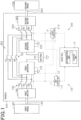
- the second drive system 200 inputs the second motor information i2 into not only the second control unit 210 but also the first control unit 110. Also, in the second abnormal state, the first drive system 100 inputs the first motor information i1 into not only the first control unit 110 but also the second control unit 210.
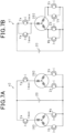
- a circuit diagram as shown in Fig. 7A can be obtained.
- the positive terminal of the battery 20 and the second motor 260 are connected to each other via one upper switch (Ya).
- the negative terminal of the battery 20 and the second motor 260 are connected to each other via two lower switches (Xb, Zb) which are parallel to each other. Therefore, the maximum value of current that can be passed through the second motor 260 corresponds to the maximum value (Imax) of current that can be passed through the single upper switch (Ya).
- the second drive system 200 inputs the second motor information i2 into the first control unit 110, and accordingly, the first control unit 110 can use the second motor information i2 to control the first inverter 120 driving the second motor 260, without any problem.
- the first drive system 100 inputs the first motor information i1 into the second control unit 210, and accordingly, the second control unit 210 can use the first motor information i 1 to control the second inverter 220 driving the first motor 160, without any problem.
- the second inverter 220 when changing state from the normal state s0 to the second countermeasure state s2, the second inverter 220 is caused to stop driving the second motor 260, and then the second switch 250 is turned OFF and at the same time the gang switch 50 is turned ON for change of state into the second countermeasure state s2.
- withstand voltage required of the second switch 250 can be minimized as in the case of the first switch 150.
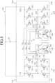
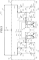
- circuit diagrams ( Figs. 2 to 5 and 7 ) indicate the upper switches (Ua, Va, Wa, Xa, Ya, Za) and the lower switches (Ub, Vb, Wb, Xb, Yb, Zb) with normal symbols of transistors; however, these switches may be MOSFETs, IGBTs, or the like.
Landscapes
- Engineering & Computer Science (AREA)
- Power Engineering (AREA)
- Transportation (AREA)
- Mechanical Engineering (AREA)
- Chemical & Material Sciences (AREA)
- Combustion & Propulsion (AREA)
- Electric Propulsion And Braking For Vehicles (AREA)
- Control Of Multiple Motors (AREA)
Claims (6)
- Drehkörperantriebssystem (300), das einen ersten Motor (160), der einen vorbestimmten ersten Drehkörper (190) antreibt, einen zweiten Motor (260), der einen zweiten Drehkörper (290), der zu dem ersten Drehkörper unterschiedlich ist, antreibt, einen ersten Wechselrichter (120), der den ersten Motor ansteuert, und einen zweiten Wechselrichter (220), der den zweiten Motor ansteuert, umfasst, wobei das Drehkörperantriebssystem umfasst:einen ersten Schalter (150), der, wenn er auf EIN geschaltet ist, eine Verbindung zwischen dem ersten Wechselrichter und dem ersten Motor herstellt, sodass ein Strom dort hindurchgeleitet werden kann, und der, wenn er auf AUS geschaltet ist, die Verbindung trennt;einen Gruppenschalter (50), der, wenn er auf EIN geschaltet ist, eine Verbindung zwischen dem ersten Wechselrichter und dem zweiten Motor herstellt, sodass ein Strom dort hindurchgeleitet werden kann, und der, wenn er auf AUS geschaltet ist, die Verbindung trennt;gekennzeichnet durcheine Bestimmungseinheit (14), die bestimmt, ob der erste Drehkörper in einem anormalen Zustand ist; undeine Steuerungseinheit (15), die den ersten Schalter und den Gruppenschalter steuert, wobeiin dem Fall, in dem die Bestimmungseinheit bestimmt, dass es keine Anomalie in dem Zustand des ersten Drehkörpers gibt, die Steuerungseinheit einen normalen Zustand (s0) etabliert, in dem der erste Schalter auf EIN ist und der Gruppenschalter auf AUS ist, um zu veranlassen, dass der erste Wechselrichter den ersten Motor ansteuert, während veranlasst wird, dass der zweite Wechselrichter den zweiten Motor ansteuert; undin dem Fall, in dem die Bestimmungseinheit bestimmt, dass es eine Anomalie in dem Zustand des ersten Drehkörpers gibt, die Steuerungseinheit einen ersten Gegenmaßnahmenzustand (s1) etabliert, in dem der erste Schalter auf AUS ist und der Gruppenschalter auf EIN ist, um zu veranlassen, dass sowohl der erste Wechselrichter als auch der zweite Wechselrichter den zweiten Motor ansteuern.
- Drehkörperantriebssystem (300) Anspruch 1, ferner mit:einem zweiten Schalter (250), der, wenn er auf EIN geschaltet ist, eine Verbindung zwischen dem zweiten Wechselrichter und dem zweiten Motor herstellt, sodass ein Strom dort hindurchgeleitet werden kann, und der, wenn er auf AUS geschaltet ist, die Verbindung trennt;wobei der Gruppenschalter (50) ferner konfiguriert ist, wenn er auf EIN geschaltet ist, eine Verbindung zwischen dem ersten Wechselrichter und dem zweiten Motor herzustellen, sodass ein Strom dort in einem Zustand, in dem der zweite Schalter auf EIN ist, hindurchgeleitet werden kann, und eine Verbindung zwischen dem zweiten Wechselrichter und dem ersten Motor herzustellen, sodass ein Strom dort in einem Zustand, in dem der erste Schalter auf EIN ist, hindurchgeleitet werden kann, und, wenn er auf AUS geschaltet ist, den ersten Wechselrichter und den zweiten Motor voneinander zu trennen, sodass kein Strom dort hindurchgeleitet werden kann, und den zweiten Wechselrichter und den ersten Motor voneinander zu trennen, sodass dort kein Strom hindurchgeleitet werden kann;wobei die Bestimmungseinheit (14) ferner konfiguriert ist, zu bestimmen, ob der erste Drehkörper und der zweite Drehkörper in einem anormalen Zustand sind; undwobei die Steuerungseinheit (15) ferner konfiguriert ist, den zweiten Schalter zu steuern, wobeiin dem Fall, in dem die Bestimmungseinheit bestimmt, dass keiner von dem ersten Drehkörper und dem zweiten Drehkörper eine Anomalie in einem Kraftschluss aufweist, die Steuerungseinheit einen normalen Zustand (s0) etabliert, in dem der erste Schalter auf EIN ist, der zweite Schalter auf EIN ist und der Gruppenschalter auf AUS ist, um zu veranlassen, dass der erste Wechselrichter den ersten Motor ansteuert, während veranlasst wird, dass der zweite Wechselrichter den zweiten Motor ansteuert;in dem Fall, in dem die Bestimmungseinheit bestimmt, dass es eine Anomalie in dem Zustand des ersten Drehkörpers gibt, die Steuerungseinheit einen ersten Gegenmaßnahmenzustand (s1) etabliert, in dem der erste Schalter auf AUS ist, der zweite Schalter auf EIN ist und der Gruppenschalter auf EIN ist, um zu veranlassen, dass sowohl der erste Wechselrichter als auch der zweite Wechselrichter den zweiten Motor ansteuern; undin dem Fall, in dem die Bestimmungseinheit bestimmt, dass es eine Anomalie in dem Zustand des zweiten Drehkörpers gibt, die Steuerungseinheit einen zweiten Gegenmaßnahmenzustand (s2) etabliert, in dem der erste Schalter auf EIN ist, der zweite Schalter auf AUS ist und der Gruppenschalter auf EIN ist, um zu veranlassen, dass sowohl der erste Wechselrichter als auch der zweite Wechselrichter den ersten Motor ansteuern.
- Drehkörperantriebssystem nach Anspruch 1 oder 2, wobeider erste Drehkörper eines von rechten und linken Rädern eines Fahrzeugs (400) ist und der zweite Drehkörper das andere der rechten und linken Räder ist; unddie Bestimmungseinheit als eine Bestimmung, ob der Zustand anormal ist, bestimmt, ob ein Kraftschluss anormal ist.
- Drehkörperantriebssystem nach einem der Ansprüche 1 bis 3, ferner miteinem ersten Antriebssystem (100), das den ersten Motor, den ersten Wechselrichter und eine vorbestimmte erste Steuerungseinheit (110), die den ersten Wechselrichter steuert, umfasst; undeinem zweiten Antriebssystem (200), das den zweiten Motor, den zweiten Wechselrichter und eine vorbestimmte zweite Steuerungseinheit (210), die den zweiten Wechselrichter steuert, umfasst, wobeiin dem ersten Gegenmaßnahmenzustand das zweite Antriebssystem vorbestimmte Informationen (i2), die auf der Grundlage des zweiten Motors, der angesteuert wird, erhalten werden, in die erste Steuerungseinheit eingibt; unddie erste Steuerungseinheit die vorbestimmten Informationen verwendet, um den ersten Wechselrichter, der den zweiten Motor ansteuert, zu steuern.
- Drehkörperantriebssystem nach einem der Ansprüche 1 bis 4, wobei,
wenn der normale Zustand zu dem ersten Gegenmaßnahmenzustand geändert wird, der erste Motor gestoppt wird, der durch den ersten Wechselrichter während des normalen Zustands angesteuert wird, wobei dann der erste Schalter für ein Ändern in den ersten Gegenmaßnahmenzustand auf AUS geschaltet wird. - Drehkörperantriebssystem nach einem der Ansprüche 1 bis 5, wobeiin dem normalen Zustand der zweite Wechselrichter veranlasst wird, den zweiten Motor mit einer Leistung anzusteuern, die kleiner oder gleich einer vorbestimmten oberen Grenzleistung ist, und in dem ersten Gegenmaßnahmenzustand der erste Wechselrichter und der zweite Wechselrichter veranlasst werden, miteinander zusammenzuarbeiten, um eine Leistung, die höher als die obere Grenzleistung ist, innerhalb einer vorbestimmten Zeitgrenze zu erzeugen, sodass der zweite Motor angesteuert wird; unddie Zeitgrenze eine Zeit ist, die auf der Grundlage einer Zeit bestimmt wird, die von dem zweiten Motor benötigt wird, um eine vorbestimmte Verschlechterung in einer Leistungsfähigkeit zu verursachen, indem er mit einer höheren Leistung als der oberen Grenzleistung angesteuert wird.
Applications Claiming Priority (2)
| Application Number | Priority Date | Filing Date | Title |
|---|---|---|---|
| JP2019181703A JP7255439B2 (ja) | 2019-10-01 | 2019-10-01 | 回転体駆動システム |
| PCT/JP2020/036485 WO2021065756A1 (ja) | 2019-10-01 | 2020-09-25 | 回転体駆動システム |
Publications (4)
| Publication Number | Publication Date |
|---|---|
| EP4040667A1 EP4040667A1 (de) | 2022-08-10 |
| EP4040667A4 EP4040667A4 (de) | 2022-11-23 |
| EP4040667B1 true EP4040667B1 (de) | 2024-07-03 |
| EP4040667C0 EP4040667C0 (de) | 2024-07-03 |
Family
ID=75271370
Family Applications (1)
| Application Number | Title | Priority Date | Filing Date |
|---|---|---|---|
| EP20871513.6A Active EP4040667B1 (de) | 2019-10-01 | 2020-09-25 | Rotorantriebssystem |
Country Status (5)
| Country | Link |
|---|---|
| US (1) | US11990855B2 (de) |
| EP (1) | EP4040667B1 (de) |
| JP (1) | JP7255439B2 (de) |
| CN (1) | CN114503422A (de) |
| WO (1) | WO2021065756A1 (de) |
Families Citing this family (3)
| Publication number | Priority date | Publication date | Assignee | Title |
|---|---|---|---|---|
| CN115833704B (zh) * | 2021-10-19 | 2025-08-05 | 宁德时代新能源科技股份有限公司 | 一种电机控制系统及其控制方法、电动车辆 |
| WO2023176295A1 (ja) * | 2022-03-16 | 2023-09-21 | 株式会社デンソー | 診断装置及びプログラム |
| JP7632497B2 (ja) * | 2022-03-16 | 2025-02-19 | 株式会社デンソー | 診断装置及びプログラム |
Family Cites Families (10)
| Publication number | Priority date | Publication date | Assignee | Title |
|---|---|---|---|---|
| JPH07194187A (ja) * | 1993-12-28 | 1995-07-28 | Toshiba Corp | 車両用空調制御装置 |
| JP5277433B2 (ja) | 2007-07-06 | 2013-08-28 | 株式会社小松製作所 | 電動車両の駆動装置 |
| JP2010268566A (ja) | 2009-05-13 | 2010-11-25 | Nissan Motor Co Ltd | 独立車輪駆動電動車の制御装置 |
| DE102010060380B3 (de) * | 2010-11-05 | 2012-02-02 | Lti Drives Gmbh | Notbetriebsfähige Pitchmotor-Antriebsschaltung |
| JP2015109775A (ja) | 2013-12-05 | 2015-06-11 | 株式会社ジェイテクト | モータ制御装置 |
| JP2017100210A (ja) | 2015-11-30 | 2017-06-08 | 株式会社デンソーウェーブ | ロボットシステム |
| US11001297B2 (en) * | 2016-03-14 | 2021-05-11 | Mitsubishi Electric Corporation | Electric motor control system and electric power steering apparatus therewith |
| JP6992517B2 (ja) * | 2018-01-09 | 2022-01-13 | トヨタ自動車株式会社 | 自動車 |
| CN108429491B (zh) * | 2018-03-14 | 2021-03-16 | 长安大学 | 一种双永磁同步电机容错控制系统及其控制方法 |
| JP7091786B2 (ja) | 2018-04-02 | 2022-06-28 | コニカミノルタ株式会社 | 画像形成装置、トレイ決定方法、およびコンピュータプログラム |
-
2019
- 2019-10-01 JP JP2019181703A patent/JP7255439B2/ja active Active
-
2020
- 2020-09-25 CN CN202080068804.9A patent/CN114503422A/zh active Pending
- 2020-09-25 EP EP20871513.6A patent/EP4040667B1/de active Active
- 2020-09-25 WO PCT/JP2020/036485 patent/WO2021065756A1/ja not_active Ceased
-
2022
- 2022-03-29 US US17/706,739 patent/US11990855B2/en active Active
Also Published As
| Publication number | Publication date |
|---|---|
| US11990855B2 (en) | 2024-05-21 |
| WO2021065756A1 (ja) | 2021-04-08 |
| EP4040667A4 (de) | 2022-11-23 |
| JP2021058054A (ja) | 2021-04-08 |
| EP4040667A1 (de) | 2022-08-10 |
| EP4040667C0 (de) | 2024-07-03 |
| CN114503422A (zh) | 2022-05-13 |
| US20220224257A1 (en) | 2022-07-14 |
| JP7255439B2 (ja) | 2023-04-11 |
Similar Documents
| Publication | Publication Date | Title |
|---|---|---|
| US11990855B2 (en) | Rotating body drive system | |
| EP3403904B1 (de) | Elektrische servolenkvorrichtung | |
| JP5731360B2 (ja) | 電力変換装置 | |
| US7909124B2 (en) | Power systems for hybrid electric vehicle (HEV) | |
| US9680405B2 (en) | Onboard motor controller | |
| US8755973B2 (en) | Vehicular power supply system | |
| US11833912B2 (en) | Traction control system | |
| CN102245424B (zh) | 扭矩控制系统 | |
| CN108778896A (zh) | 电动机控制系统及具备电动机控制系统的电动助力转向装置 | |
| US9731605B2 (en) | Method and apparatus for controlling an electrified powertrain system of a vehicle | |
| JP2013247754A (ja) | 電動機の駆動制御装置 | |
| JP6799674B2 (ja) | 車両 | |
| US11533015B2 (en) | Drive device-integrated rotary electric machine and electric power steering device using same | |
| CA2936680A1 (en) | Redundant drive system | |
| WO2016031696A1 (ja) | 車輪独立駆動式車両の駆動制御装置 | |
| JP2016073061A (ja) | 電気自動車の制御装置 | |
| JP7298433B2 (ja) | 回転電機システム | |
| US10819267B2 (en) | Controller for switched reluctance motor | |
| JP2016063587A (ja) | 車両の駆動制御装置 | |
| CN112953350A (zh) | 回转机械控制装置以及控制方法 | |
| WO2025164218A1 (ja) | 回転電機の制御装置、プログラム、及び回転電機の制御方法 | |
| JP7631745B2 (ja) | インバータ制御装置、プログラム | |
| CN120792527A (zh) | 电机控制系统、方法、动力总成以及车辆 |
Legal Events
| Date | Code | Title | Description |
|---|---|---|---|
| STAA | Information on the status of an ep patent application or granted ep patent |
Free format text: STATUS: THE INTERNATIONAL PUBLICATION HAS BEEN MADE |
|
| PUAI | Public reference made under article 153(3) epc to a published international application that has entered the european phase |
Free format text: ORIGINAL CODE: 0009012 |
|
| STAA | Information on the status of an ep patent application or granted ep patent |
Free format text: STATUS: REQUEST FOR EXAMINATION WAS MADE |
|
| 17P | Request for examination filed |
Effective date: 20220411 |
|
| AK | Designated contracting states |
Kind code of ref document: A1 Designated state(s): AL AT BE BG CH CY CZ DE DK EE ES FI FR GB GR HR HU IE IS IT LI LT LU LV MC MK MT NL NO PL PT RO RS SE SI SK SM TR |
|
| STAA | Information on the status of an ep patent application or granted ep patent |
Free format text: STATUS: EXAMINATION IS IN PROGRESS |
|
| A4 | Supplementary search report drawn up and despatched |
Effective date: 20221020 |
|
| RIC1 | Information provided on ipc code assigned before grant |
Ipc: B60L 7/00 20060101ALI20221014BHEP Ipc: B60L 15/00 20060101ALI20221014BHEP Ipc: B60L 9/18 20060101ALI20221014BHEP Ipc: B60L 3/00 20190101ALI20221014BHEP Ipc: H02P 5/46 20060101AFI20221014BHEP |
|
| 17Q | First examination report despatched |
Effective date: 20221115 |
|
| DAV | Request for validation of the european patent (deleted) | ||
| DAX | Request for extension of the european patent (deleted) | ||
| REG | Reference to a national code |
Ref legal event code: R079 Free format text: PREVIOUS MAIN CLASS: H02P0005460000 Ipc: B60K0007000000 Ref country code: DE Ref legal event code: R079 Ref document number: 602020033532 Country of ref document: DE Free format text: PREVIOUS MAIN CLASS: H02P0005460000 Ipc: B60K0007000000 |
|
| GRAP | Despatch of communication of intention to grant a patent |
Free format text: ORIGINAL CODE: EPIDOSNIGR1 |
|
| STAA | Information on the status of an ep patent application or granted ep patent |
Free format text: STATUS: GRANT OF PATENT IS INTENDED |
|
| RIC1 | Information provided on ipc code assigned before grant |
Ipc: B60L 15/00 20060101ALI20240105BHEP Ipc: B60L 7/00 20060101ALI20240105BHEP Ipc: H02P 29/028 20160101ALI20240105BHEP Ipc: H02P 5/74 20060101ALI20240105BHEP Ipc: B60K 7/00 20060101AFI20240105BHEP |
|
| INTG | Intention to grant announced |
Effective date: 20240124 |
|
| GRAS | Grant fee paid |
Free format text: ORIGINAL CODE: EPIDOSNIGR3 |
|
| GRAA | (expected) grant |
Free format text: ORIGINAL CODE: 0009210 |
|
| STAA | Information on the status of an ep patent application or granted ep patent |
Free format text: STATUS: THE PATENT HAS BEEN GRANTED |
|
| AK | Designated contracting states |
Kind code of ref document: B1 Designated state(s): AL AT BE BG CH CY CZ DE DK EE ES FI FR GB GR HR HU IE IS IT LI LT LU LV MC MK MT NL NO PL PT RO RS SE SI SK SM TR |
|
| REG | Reference to a national code |
Ref country code: CH Ref legal event code: EP |
|
| REG | Reference to a national code |
Ref country code: DE Ref legal event code: R096 Ref document number: 602020033532 Country of ref document: DE |
|
| U01 | Request for unitary effect filed |
Effective date: 20240709 |
|
| U07 | Unitary effect registered |
Designated state(s): AT BE BG DE DK EE FI FR IT LT LU LV MT NL PT SE SI Effective date: 20240719 |
|
| U20 | Renewal fee for the european patent with unitary effect paid |
Year of fee payment: 5 Effective date: 20240925 |
|
| PG25 | Lapsed in a contracting state [announced via postgrant information from national office to epo] |
Ref country code: NO Free format text: LAPSE BECAUSE OF FAILURE TO SUBMIT A TRANSLATION OF THE DESCRIPTION OR TO PAY THE FEE WITHIN THE PRESCRIBED TIME-LIMIT Effective date: 20241003 |
|
| PG25 | Lapsed in a contracting state [announced via postgrant information from national office to epo] |
Ref country code: PL Free format text: LAPSE BECAUSE OF FAILURE TO SUBMIT A TRANSLATION OF THE DESCRIPTION OR TO PAY THE FEE WITHIN THE PRESCRIBED TIME-LIMIT Effective date: 20240703 Ref country code: GR Free format text: LAPSE BECAUSE OF FAILURE TO SUBMIT A TRANSLATION OF THE DESCRIPTION OR TO PAY THE FEE WITHIN THE PRESCRIBED TIME-LIMIT Effective date: 20241004 |
|
| PG25 | Lapsed in a contracting state [announced via postgrant information from national office to epo] |
Ref country code: IS Free format text: LAPSE BECAUSE OF FAILURE TO SUBMIT A TRANSLATION OF THE DESCRIPTION OR TO PAY THE FEE WITHIN THE PRESCRIBED TIME-LIMIT Effective date: 20241103 |
|
| PG25 | Lapsed in a contracting state [announced via postgrant information from national office to epo] |
Ref country code: HR Free format text: LAPSE BECAUSE OF FAILURE TO SUBMIT A TRANSLATION OF THE DESCRIPTION OR TO PAY THE FEE WITHIN THE PRESCRIBED TIME-LIMIT Effective date: 20240703 Ref country code: CZ Free format text: LAPSE BECAUSE OF FAILURE TO SUBMIT A TRANSLATION OF THE DESCRIPTION OR TO PAY THE FEE WITHIN THE PRESCRIBED TIME-LIMIT Effective date: 20240703 |
|
| PG25 | Lapsed in a contracting state [announced via postgrant information from national office to epo] |
Ref country code: ES Free format text: LAPSE BECAUSE OF FAILURE TO SUBMIT A TRANSLATION OF THE DESCRIPTION OR TO PAY THE FEE WITHIN THE PRESCRIBED TIME-LIMIT Effective date: 20240703 Ref country code: RS Free format text: LAPSE BECAUSE OF FAILURE TO SUBMIT A TRANSLATION OF THE DESCRIPTION OR TO PAY THE FEE WITHIN THE PRESCRIBED TIME-LIMIT Effective date: 20241003 |
|
| PG25 | Lapsed in a contracting state [announced via postgrant information from national office to epo] |
Ref country code: RS Free format text: LAPSE BECAUSE OF FAILURE TO SUBMIT A TRANSLATION OF THE DESCRIPTION OR TO PAY THE FEE WITHIN THE PRESCRIBED TIME-LIMIT Effective date: 20241003 Ref country code: PL Free format text: LAPSE BECAUSE OF FAILURE TO SUBMIT A TRANSLATION OF THE DESCRIPTION OR TO PAY THE FEE WITHIN THE PRESCRIBED TIME-LIMIT Effective date: 20240703 Ref country code: NO Free format text: LAPSE BECAUSE OF FAILURE TO SUBMIT A TRANSLATION OF THE DESCRIPTION OR TO PAY THE FEE WITHIN THE PRESCRIBED TIME-LIMIT Effective date: 20241003 Ref country code: IS Free format text: LAPSE BECAUSE OF FAILURE TO SUBMIT A TRANSLATION OF THE DESCRIPTION OR TO PAY THE FEE WITHIN THE PRESCRIBED TIME-LIMIT Effective date: 20241103 Ref country code: HR Free format text: LAPSE BECAUSE OF FAILURE TO SUBMIT A TRANSLATION OF THE DESCRIPTION OR TO PAY THE FEE WITHIN THE PRESCRIBED TIME-LIMIT Effective date: 20240703 Ref country code: GR Free format text: LAPSE BECAUSE OF FAILURE TO SUBMIT A TRANSLATION OF THE DESCRIPTION OR TO PAY THE FEE WITHIN THE PRESCRIBED TIME-LIMIT Effective date: 20241004 Ref country code: ES Free format text: LAPSE BECAUSE OF FAILURE TO SUBMIT A TRANSLATION OF THE DESCRIPTION OR TO PAY THE FEE WITHIN THE PRESCRIBED TIME-LIMIT Effective date: 20240703 Ref country code: CZ Free format text: LAPSE BECAUSE OF FAILURE TO SUBMIT A TRANSLATION OF THE DESCRIPTION OR TO PAY THE FEE WITHIN THE PRESCRIBED TIME-LIMIT Effective date: 20240703 |
|
| PG25 | Lapsed in a contracting state [announced via postgrant information from national office to epo] |
Ref country code: SM Free format text: LAPSE BECAUSE OF FAILURE TO SUBMIT A TRANSLATION OF THE DESCRIPTION OR TO PAY THE FEE WITHIN THE PRESCRIBED TIME-LIMIT Effective date: 20240703 |
|
| PG25 | Lapsed in a contracting state [announced via postgrant information from national office to epo] |
Ref country code: MC Free format text: LAPSE BECAUSE OF FAILURE TO SUBMIT A TRANSLATION OF THE DESCRIPTION OR TO PAY THE FEE WITHIN THE PRESCRIBED TIME-LIMIT Effective date: 20240703 |
|
| PG25 | Lapsed in a contracting state [announced via postgrant information from national office to epo] |
Ref country code: SK Free format text: LAPSE BECAUSE OF FAILURE TO SUBMIT A TRANSLATION OF THE DESCRIPTION OR TO PAY THE FEE WITHIN THE PRESCRIBED TIME-LIMIT Effective date: 20240703 |
|
| REG | Reference to a national code |
Ref country code: CH Ref legal event code: PL |
|
| PLBE | No opposition filed within time limit |
Free format text: ORIGINAL CODE: 0009261 |
|
| STAA | Information on the status of an ep patent application or granted ep patent |
Free format text: STATUS: NO OPPOSITION FILED WITHIN TIME LIMIT |
|
| 26N | No opposition filed |
Effective date: 20250404 |
|
| GBPC | Gb: european patent ceased through non-payment of renewal fee |
Effective date: 20241003 |
|
| PG25 | Lapsed in a contracting state [announced via postgrant information from national office to epo] |
Ref country code: GB Free format text: LAPSE BECAUSE OF NON-PAYMENT OF DUE FEES Effective date: 20241003 |
|
| PG25 | Lapsed in a contracting state [announced via postgrant information from national office to epo] |
Ref country code: CH Free format text: LAPSE BECAUSE OF NON-PAYMENT OF DUE FEES Effective date: 20240930 |
|
| PG25 | Lapsed in a contracting state [announced via postgrant information from national office to epo] |
Ref country code: IE Free format text: LAPSE BECAUSE OF NON-PAYMENT OF DUE FEES Effective date: 20240925 |
|
| U20 | Renewal fee for the european patent with unitary effect paid |
Year of fee payment: 6 Effective date: 20250924 |
|
| PG25 | Lapsed in a contracting state [announced via postgrant information from national office to epo] |
Ref country code: RO Free format text: LAPSE BECAUSE OF FAILURE TO SUBMIT A TRANSLATION OF THE DESCRIPTION OR TO PAY THE FEE WITHIN THE PRESCRIBED TIME-LIMIT Effective date: 20240703 |