US11001297B2 - Electric motor control system and electric power steering apparatus therewith - Google Patents
Electric motor control system and electric power steering apparatus therewith Download PDFInfo
- Publication number
- US11001297B2 US11001297B2 US16/070,341 US201616070341A US11001297B2 US 11001297 B2 US11001297 B2 US 11001297B2 US 201616070341 A US201616070341 A US 201616070341A US 11001297 B2 US11001297 B2 US 11001297B2
- Authority
- US
- United States
- Prior art keywords
- windings
- electric motor
- current
- control system
- abnormality
- Prior art date
- Legal status (The legal status is an assumption and is not a legal conclusion. Google has not performed a legal analysis and makes no representation as to the accuracy of the status listed.)
- Active, expires
Links
Images


Classifications
-
- B—PERFORMING OPERATIONS; TRANSPORTING
- B62—LAND VEHICLES FOR TRAVELLING OTHERWISE THAN ON RAILS
- B62D—MOTOR VEHICLES; TRAILERS
- B62D5/00—Power-assisted or power-driven steering
- B62D5/04—Power-assisted or power-driven steering electrical, e.g. using an electric servo-motor connected to, or forming part of, the steering gear
- B62D5/0457—Power-assisted or power-driven steering electrical, e.g. using an electric servo-motor connected to, or forming part of, the steering gear characterised by control features of the drive means as such
- B62D5/0481—Power-assisted or power-driven steering electrical, e.g. using an electric servo-motor connected to, or forming part of, the steering gear characterised by control features of the drive means as such monitoring the steering system, e.g. failures
- B62D5/0484—Power-assisted or power-driven steering electrical, e.g. using an electric servo-motor connected to, or forming part of, the steering gear characterised by control features of the drive means as such monitoring the steering system, e.g. failures for reaction to failures, e.g. limp home
-
- B—PERFORMING OPERATIONS; TRANSPORTING
- B62—LAND VEHICLES FOR TRAVELLING OTHERWISE THAN ON RAILS
- B62D—MOTOR VEHICLES; TRAILERS
- B62D5/00—Power-assisted or power-driven steering
- B62D5/04—Power-assisted or power-driven steering electrical, e.g. using an electric servo-motor connected to, or forming part of, the steering gear
- B62D5/0457—Power-assisted or power-driven steering electrical, e.g. using an electric servo-motor connected to, or forming part of, the steering gear characterised by control features of the drive means as such
- B62D5/046—Controlling the motor
-
- B—PERFORMING OPERATIONS; TRANSPORTING
- B62—LAND VEHICLES FOR TRAVELLING OTHERWISE THAN ON RAILS
- B62D—MOTOR VEHICLES; TRAILERS
- B62D5/00—Power-assisted or power-driven steering
- B62D5/04—Power-assisted or power-driven steering electrical, e.g. using an electric servo-motor connected to, or forming part of, the steering gear
- B62D5/0457—Power-assisted or power-driven steering electrical, e.g. using an electric servo-motor connected to, or forming part of, the steering gear characterised by control features of the drive means as such
- B62D5/0481—Power-assisted or power-driven steering electrical, e.g. using an electric servo-motor connected to, or forming part of, the steering gear characterised by control features of the drive means as such monitoring the steering system, e.g. failures
- B62D5/0487—Power-assisted or power-driven steering electrical, e.g. using an electric servo-motor connected to, or forming part of, the steering gear characterised by control features of the drive means as such monitoring the steering system, e.g. failures detecting motor faults
-
- H—ELECTRICITY
- H02—GENERATION; CONVERSION OR DISTRIBUTION OF ELECTRIC POWER
- H02P—CONTROL OR REGULATION OF ELECTRIC MOTORS, ELECTRIC GENERATORS OR DYNAMO-ELECTRIC CONVERTERS; CONTROLLING TRANSFORMERS, REACTORS OR CHOKE COILS
- H02P25/00—Arrangements or methods for the control of AC motors characterised by the kind of AC motor or by structural details
- H02P25/16—Arrangements or methods for the control of AC motors characterised by the kind of AC motor or by structural details characterised by the circuit arrangement or by the kind of wiring
- H02P25/22—Multiple windings; Windings for more than three phases
-
- H—ELECTRICITY
- H02—GENERATION; CONVERSION OR DISTRIBUTION OF ELECTRIC POWER
- H02P—CONTROL OR REGULATION OF ELECTRIC MOTORS, ELECTRIC GENERATORS OR DYNAMO-ELECTRIC CONVERTERS; CONTROLLING TRANSFORMERS, REACTORS OR CHOKE COILS
- H02P29/00—Arrangements for regulating or controlling electric motors, appropriate for both AC and DC motors
- H02P29/02—Providing protection against overload without automatic interruption of supply
- H02P29/032—Preventing damage to the motor, e.g. setting individual current limits for different drive conditions
-
- H—ELECTRICITY
- H02—GENERATION; CONVERSION OR DISTRIBUTION OF ELECTRIC POWER
- H02P—CONTROL OR REGULATION OF ELECTRIC MOTORS, ELECTRIC GENERATORS OR DYNAMO-ELECTRIC CONVERTERS; CONTROLLING TRANSFORMERS, REACTORS OR CHOKE COILS
- H02P6/00—Arrangements for controlling synchronous motors or other dynamo-electric motors using electronic commutation dependent on the rotor position; Electronic commutators therefor
- H02P6/12—Monitoring commutation; Providing indication of commutation failure
-
- H—ELECTRICITY
- H02—GENERATION; CONVERSION OR DISTRIBUTION OF ELECTRIC POWER
- H02P—CONTROL OR REGULATION OF ELECTRIC MOTORS, ELECTRIC GENERATORS OR DYNAMO-ELECTRIC CONVERTERS; CONTROLLING TRANSFORMERS, REACTORS OR CHOKE COILS
- H02P6/00—Arrangements for controlling synchronous motors or other dynamo-electric motors using electronic commutation dependent on the rotor position; Electronic commutators therefor
- H02P6/28—Arrangements for controlling current
Definitions
- the present disclosure relates to an electric motor control system including an electric motor which is provided with a stator equipped with 2 sets of plural phase windings and a rotor equipped with a permanent magnet and drives a steering mechanism of a vehicle, and a controller which controls the electric motor, and an electric power steering apparatus therewith.
- PLT 1 With regard to the above electric motor control system, the technology described in PLT 1 is already known.
- a supply current to 2 sets of the windings provided in the electric motor is controlled by 2 sets of control systems.
- a supply current to the windings of the abnormality occurrence set is set to 0, and drive of the electric motor is continued by performing electric power supply to the normal set of the windings.
- An electric motor control system including:
- the electric motor is provided with a stator equipped with 2 sets of plural phase windings, and a rotor equipped with a permanent magnet, and
- controller is provided with 2 sets of control systems which control a supply current to each set of the windings;
- the controller distributes and supplies current to 2 sets of the windings;
- the controller sets 0 to the supply current to all phase or partial phase windings of an abnormality occurrence set, and increases the supply current to a normal set of the windings up to an irreversible current that increase an irreversible demagnetizing factor of the permanent magnet more than normal time.
- An electric power steering apparatus according to the present disclosure is provided with the above electric motor control system.
- the electric motor control system When abnormality occurs in one set, the electric motor control system increases the supply current to the normal set of the windings up to the irreversible current that increase the irreversible demagnetizing factor of the permanent magnet more than normal time. Therefore, even at the time of abnormality occurrence, torque of the electric motor can be increased and steering performance can be ensured. Thus, by sacrificing deterioration of irreversible demagnetizing factor, deterioration of the steering performance at the time of abnormality occurrence is suppressed, and priority is given to ensuring of driving performance.
- FIG. 1 is a schematic configuration diagram of an electric motor control system according to Embodiment 1;
- FIG. 2 is a schematic configuration diagram of an electric power steering device according to Embodiment 1;
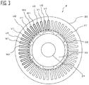
- FIG. 3 is a cross-sectional view of an electric motor according to Embodiment 1;
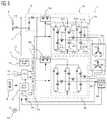
- FIG. 4 is a schematic block diagram of a control circuit according to Embodiment 1;
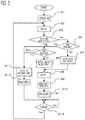
- FIG. 5 is a flowchart for explaining processing of a control circuit according to Embodiment 1;
- FIG. 6 is a schematic configuration diagram of an electric motor control system according to Embodiment 5.
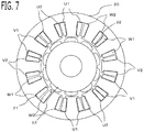
- FIG. 7 is a cross-sectional view of an electric motor according to Embodiment 5.
- FIG. 8 is a FIG. for explaining a winding connection according to Embodiment 5;
- FIG. 9 is a cross-sectional view of an electric motor according to Embodiment 6.
- FIG. 10 is a figure showing a deterioration rate of demagnetizing factor according to Embodiment 5.
- FIG. 11 is a figure showing an increase rate of torque according to Embodiment 5.
- FIG. 1 is a schematic configuration diagram of the electric motor control system 1 according to the present embodiment.
- the electric motor control system 1 is provided with an electric motor 2 which drives a steering mechanism of a vehicle, and a controller 18 which controls the electric motor 2 . That is to say, the electric motor control system 1 performs driving control of the electric motor 2 , and steers the handle.
- the electric motor control system 1 is built into an electric power steering apparatus 60 .
- the electric power steering apparatus 60 will be explained.
- a handle 61 which a driver operates is connected with a steering shaft 62 .
- a torque sensor 63 which detects a steering force of the driver is attached to the steering shaft 62 .
- the steering shaft 62 is connected with a pinion gear 66 in a rack shaft 65 via an intermediate shaft 64 .
- Knuckle arms 68 a and 68 b of front wheels 67 a and 67 b which are steering control wheels are connected to tie rods 69 a and 69 b connected with the rack shaft 65 .
- the front wheels 67 a and 67 b are steered, when a motion of the rack shaft 65 transmits to the front wheels 67 a and 67 b through the tie rods 69 a and 69 b and the steering knuckle arms 68 a and 68 b .
- the rack shaft 65 is connected with the electric motor 2 via gears, and a rotational driving force of the electric motor 2 is a driving force for driving the rack shaft 65 .
- the electric power steering apparatus 60 constituted in this way, when the driver steers the handle 61 , a torque signal according to steering is transmitted to the controller 18 from the torque sensor 63 , The controller 18 calculates a required assist torque based on vehicle signals, such as the torque signal and vehicle speed, and controls a supply current to the electric motor 2 so that the electric motor 2 outputs the assist torque.
- vehicle signals such as the torque signal and vehicle speed
- the electric motor 2 is provided with a stator 20 which has 2 sets of plural phase windings (in this example, three phase windings), and a rotor 23 which has a permanent magnet 22 .
- the electric motor 2 is a brush-less motor whose three phase windings of each set is delta connection, respectively.
- the electric motor 2 mounts rotation sensors 9 a and 9 b for detecting rotational position of the rotor.
- the rotation sensors 9 a and 9 b are 2 sets of sensors, in order to ensure redundant system, and an output signal of each sensor is inputted into an input circuit 12 of a control circuit 4 . 2 sets of sensors may be packed into one package and be mounted in one place, or may be independently mounted in two places.
- the electric motor 2 may be a brush-less motor whose three phase windings is star connection, or may be a motor with a brush of two poles and two pairs.
- FIG. 3 shows a cross-sectional view cut by a plane perpendicular to an axial direction of the electric motor 2 .
- the stator 20 is constituted by laminating thin steel plates in which a plurality of slots 21 (in this example, 48 slots) are arranged circumferentially.
- the rotor 23 is concentrically arranged in the radial-direct ion inner side of this stator 20 .
- the permanent magnets 22 are arranged in order of N pole and S pole in the peripheral direction (in this example, 8 poles). It may not be surface magnet structure, but embedded magnet structure in which the permanent magnets 22 are embedded inside the rotor 23 .
- An output shaft 24 is provided in the center of the rotor 23 , and a gear is allocated in the end of the output shaft 24 and is connected with the steering apparatus of the handle. Therefore, the assist force which assists handle operation is exhibited by the rotational driving force of the output shaft 24 .
- the controller 18 controls the output of the electric motor 2 so that desired assist force is obtained.
- a plurality of windings (for example, 4) is arranged at each slot 21 of the stator 20 .
- the winding which extended from each slot 21 is wound, and the left half of FIG. 3 shows those states partially.
- the first set of windings and the second set of windings are arranged at slot 21 adjacent to each other.
- the winding of first set of U phase (U 1 ) which is inserted in the predetermined slot 21 , extends to outside of the slot 21 , and then is again inserted in the 6th slot 21 beyond five slots.
- the winding of the second set of U phase (U 2 ) is inserted; in the slot 21 adjacent to U 2 , the winding of the first set of V phase (V 1 ) is inserted; in the slot 21 adjacent to V 1 , the winding of the second set of V phase (V 2 ) is inserted; in the slot 21 adjacent to V 2 , the winding of the first set of W phase (W 1 ) is inserted; and in the slot 21 adjacent to W 1 , the winding of the second set of W phase (W 2 ) is inserted.
- the windings are inserted regularly.
- 2 sets of the windings are alternately wound in the peripheral direction, and are distributed winding with a preliminarily set phase difference (in this example, 7.5 degrees).
- Each set of windings are connected so that the end of each phase winding becomes delta connection.
- 2 sets of the windings are distributed in the peripheral direction of one stator, it may be so-called a tandem type motor which arranges a stator equipped with the first set of windings and a stator equipped with the second set of windings in series for one rotor.
- the tandem type motor may become long in the axial direction, and mountability may be deteriorated.
- the controller 18 is provided with 2 sets of control systems which control the supply current to each set of the windings.
- the controller 18 is provided with 2 sets of inverters 3 a and 3 b which supply AC power to each set of the three phase windings, and a control circuit 4 which controls each set of the inverters 3 a and 3 b .
- the first set of inverter 3 a converts DC power supplied from the DC power source 6 (in this example, vehicle battery) into AC power, and supplies to the first set of windings U 1 , V 1 , and W 1 .
- the second set of inverter 3 b converts DC power supplied from the DC power source 6 into AC power, and supplies to the second set of windings U 2 , V 2 , and W 2 . Power is supplied to a power supply circuit 13 of the control circuit 4 from the DC power source 6 via an ignition switch 7 .
- the first set of inverter 3 a is provided with three sets of a series circuit (leg) where a positive electrode side switching device 31 (upper arm) connected to the positive electrode terminal of the DC power source 6 and a negative electrode side switching device 32 (lower arm) connected to the negative electrode terminal of the DC power source 6 are connected in series, corresponding to respective phase of the three phase windings.
- the first set of inverter 3 a is provided with a total of six switching devices for power conversion of the three positive electrode side switching devices 31 U, 31 V, and 31 W and the three negative electrode side switching devices 32 U, 32 V, and 32 W.
- a free-wheel diode is connected in inverse parallel to each switching device.
- connection node of the positive electrode side switching device 31 and the negative electrode side switching device 32 of each phase is connected to the winding of the corresponding phase in the first set of windings U 1 , V 1 , and W 1 .
- a switching device 34 U, 34 V, and 34 W for motor relay as a relay circuit is provided, respectively.
- a shunt resistance 33 U, 33 V, and 33 W for current detection is provided in the series circuit (leg) of each phase, respectively. The both-ends potential difference of the shunt resistance 33 U, 33 V, and 33 W is inputted into the control circuit 4 , respectively.
- a switching device 5 a for power source relay of first set On a power source line from the DC power source 6 to the first set of inverter 3 a , a switching device 5 a for power source relay of first set is provided.
- the switching device 31 U, 31 V, 31 W, 32 U, 32 V, 32 W, 34 U, 34 V, 34 W, and 5 a is turned on and off by a control signal outputted from a first driving circuit 11 a of the control circuit 4 , respectively.
- the second set of inverter 3 b is constituted similar to the first set of inverter 3 a . That is to say, the second set of inverter 3 b is provided with six switching devices 31 U, 31 V, 31 W, 32 U, 32 V, and 32 W for power conversion, switching devices 34 U, 34 V, and 34 W for motor relay, shunt resistances 33 U, 33 V, and 33 W, and a switching device 5 b for power source relay of second set.
- the switching device 31 U, 31 V, 31 W, 32 U, 32 V, 32 W, 34 U, 34 V, 34 W, and 5 b is turned on and off by a control signal outputted from a second driving circuit 11 b of the control circuit 4 , respectively.
- the control circuit 4 is provided with a first motor current control unit 40 a that controls current supplied to the first set of windings U 1 , V 1 , and W 1 by controlling the first set of inverter 3 a , a second motor current control unit 40 b that controls current supplied to the second set of windings U 2 , V 2 , and W 2 by controlling the second set of inverter 3 b , a first abnormality detection unit 41 a that detects abnormality of the first set of control system, and a second abnormality detection unit 41 b that detects abnormality of the second set of control system.
- control circuit 4 includes, as processing circuits, a arithmetic: processor 10 (computer) such as a CPU (Central Processing Unit), storage apparatuses 17 that exchange data with the arithmetic processor 10 , an input circuit 12 that inputs external signals to the arithmetic processor 10 , an output circuit that outputs signals from the arithmetic: processor 10 to the outside, and the like.
- a arithmetic: processor 10 computer
- CPU Central Processing Unit
- storage apparatuses 17 that exchange data with the arithmetic processor 10
- input circuit 12 that inputs external signals to the arithmetic processor 10
- output circuit that outputs signals from the arithmetic: processor 10 to the outside, and the like.
- a RAM Random Access Memory
- a ROM Read Only Memory
- the input circuit 12 is connected with various kinds of sensors and switches and is provided with an A/D converter and the like for inputting output signals from the sensors and the switches to the arithmetic processor 10 .
- the output circuit is connected with electric loads such as a driving circuit 11 that drive on/off of the switching devices and an informing device driving circuit 16 ; and is provided with a driving circuit and the like for outputting a control signal from the arithmetic processor 10 .
- the input circuit 12 is connected with various sensors 8 , such as the shunt resistances 33 as current sensors, the rotation sensors 9 a and 9 b , the voltage sensors of the DC power source and the winding terminals, the torque sensor 63 for detecting the steering wheel torque of the handle, and a vehicle speed sensor for detecting the travelling speed of the vehicle.
- the driving circuit 11 is connected with each switching device.
- the arithmetic processor 10 runs software items (programs) stored in the storage apparatus 17 such as a ROM and collaborates with other hardware devices in the control circuit 4 , such as the storage apparatus 17 , the input circuit 12 , and the output circuit, so that the each function of the control units 40 a , 40 b , 41 a , and 41 b provided in the control circuit 4 are realized.
- software items programs stored in the storage apparatus 17 such as a ROM and collaborates with other hardware devices in the control circuit 4 , such as the storage apparatus 17 , the input circuit 12 , and the output circuit, so that the each function of the control units 40 a , 40 b , 41 a , and 41 b provided in the control circuit 4 are realized.
- the first set of control system and the second set of control system are independent of each other.
- the control circuit 4 is provided with a first arithmetic processor 10 a (in this example, CPU 1 ), a first storage apparatus 17 a only for the first arithmetic processor 10 a , and a first driving circuit 11 a only for the first arithmetic processor 10 a .
- the control circuit 4 is provided with a second arithmetic processor 10 b (in this example, CPU 2 ), a second storage apparatus 17 b only for the second arithmetic processor 10 b , and a second driving circuit 11 b only for the second arithmetic processor 10 b .
- the first arithmetic processor 10 a and the second arithmetic processor 10 b are connected by a communication line 14 , and can transmit information with each other.
- the input circuit 12 is commonly used for the first and second arithmetic processors 10 a and 10 b .
- the control circuit 4 is provided with the common informing device driving circuit 16 for driving an informing device 15 .
- the first and second motor current control units 40 a and 40 b calculate the assist torque which the electric motor 2 outputs, based on the vehicle speed and the steering wheel torque detected based on the output signal of the torque sensor 63 , Then, each of the first and second motor current control units 40 a and 40 b calculates a current command of each set of the windings, based on a divided assist torque obtained by multiplying a dividing ratio of each set (1 ⁇ 2 at normal time) to the assist torque, respectively, Each of the first and second motor current control units 40 a and 40 b controls on/off of each set of the switching devices by current feedback control using the vector control method, respectively.
- each of the first and second motor current control units 40 a and 40 b calculates dq-axis current commands represented in a dq-axis rotating coordinate system, based on the divided assist torque, respectively.
- the dq-axis current commands are calculated, according to the maximum torque current control method that calculates the dq-axis current commands which maximize the generated torque for the same current.
- the dq-axis rotating system consists of a d-axis defined in the direction of the N pole (magnetic pole position) of the permanent magnet provided in the rotor and a q-axis defined in the direction advanced to d-axis by 90 degrees (n/2) in an electrical angle, and which is the two-axis rotating coordinate system which rotates synchronizing with rotation of the rotor in the electrical angle.
- Each of the first and second motor current control units 40 a and 40 b calculates the dq-axis voltage commands by proportional-integral control and the like, based on a deviation between current commands and actual currents, in the dq-axis (2 phases) rotating coordinate system; and calculates three phase voltage commands by performing a fixed coordinate conversion and a two-phase/three-phase conversion to the dq-axis voltage commands, respectively. Then, each of the control units perform PWM (Pulse Width Modulation) controls that change a duty ratio of rectangular pulse wave signal which turns on or turns off the switching devices of each phase by comparing the three phase voltage commands with a carrier, respectively.
- PWM Pulse Width Modulation
- Each of the first and second abnormality detection units 41 a and 41 b detects abnormality of each set of control systems, such as inverters 3 a and 3 b and windings, from sensor information, such as current detecting values, respectively.
- each of the first and second motor current control units 40 a and 40 b about the set in which abnormality occurred, turns off the switching devices 34 for motor relay of all phases or phase in which abnormality occurred; shuts down current supply to the windings of all phases or phase in which abnormality occurred; and prevents a counter electromotive force generated by rotation of the electric motor 2 from being applied to the inverter 3 a and 3 b .
- the switching devices 34 U, 34 V, and 34 W for motor relay of all phases of the abnormality occurrence set are turned off, it becomes unnecessary to consider the counter electromotive force generated in the windings of the abnormality occurrence set.
- each of the first, and second motor current control units 40 a and 40 b may turn off the switching device 5 a and 5 b for power source relay of the set in which abnormality occurred.
- each of the first and second motor current control units 40 a and 40 b may set 0 to the current commands of the set in which abnormality occurred, or may turn off the switching devices of the upper and lower arms of the inverter 3 a and 3 b of the set in which abnormality occurred.
- each of the first and second abnormality detection units 41 a and 41 b supplies power and turns on the informing device 15 , such as a lamp, via the informing device driving circuit 16 ; and informs that abnormality of one set occurred.
- the switching device 5 a and 5 b for power source relay may be included in the inverter 3 a and 3 b , respectively.
- Each of the first and second arithmetic processors 10 a and 10 b monitors a mutual operating state by mutual information transfer through the communication line 14 , respectively.
- the first arithmetic processor 10 a (the first abnormality detection unit 41 a ) transmits that the first arithmetic processor 10 a detected abnormality of the first control system and turned off the predetermined switching devices, to the second arithmetic processor 10 b (the second motor current control unit 40 b ).
- each of the first and second arithmetic processors 10 a and 10 b determines that abnormality has occurred in the other arithmetic processor, and determines that current supply of the other control system has stopped, respectively.
- each of the first and second arithmetic processors 10 a and 10 b detects abnormality of own or the other arithmetic processor, each of the first and second arithmetic processors 10 a and 10 b informs that abnormality has occurred via the informing device 15 , respectively,
- abnormality detection processing will be explained along with flowchart of FIG. 5 . Since the first and second arithmetic processors 10 a and 10 b perform similar processing, processing of the first arithmetic processor 10 a is explained as a representative.
- the first arithmetic processor 10 a When the ignition switch 7 is turned on, power is supplied to the first arithmetic processor 10 a , and the first arithmetic processor 10 a starts processing of each control unit.
- the first arithmetic processor 10 a initializes RAM memory, ROM memory, input/output port, and the like.
- the first motor current control unit 40 a obtains various kinds of information inputted via the input circuit 12 , and stores it in RAM memory. In that information, the communications data of the other second arithmetic processor 10 b is also included.
- the first abnormality detection unit 41 a checks presence/absence of abnormality detection of the other second set of control system.
- the presence/absence of abnormality of the second set of control system can be determined by decoding communications data with the second arithmetic processor 10 b .
- the first abnormality detection unit 41 a advances to the step S 4 and checks presence/absence of abnormality detection of the own first set of control system.
- the first motor current control unit 40 a advances to the step S 5 and calculates normal control amount 1 for when abnormality of the first set and second set of control systems does not occur.
- the first abnormality detection unit 41 a advances to the step S 6 and checks presence/absence of abnormality detection of the own first set of control system, as well as the step S 4 .
- the first motor current control unit 40 a advances to the step S 11 and performs processing at the own abnormal time.
- the first motor current control unit 40 a advances to the step S 7 and calculates control amount 2 in conditions of abnormal in the other and normal in own, and then advances to the step S 8 .
- the first motor current control unit 40 a advances to the step S 11 and outputs a control signal so as to stop output of the first driving circuit 11 a .
- the first motor current control unit 40 a may classify into plural levels based on the abnormality content which occurred. For example, when ground fault or power short-circuit occurs in the winding of the electric motor 2 or the switching device of the inverter 3 a , the first motor current control unit 40 a outputs control signal so as to turn off all switching devices including the switching device 5 a for power source relay.
- the first motor current control unit 40 a can also stop the drive of the switching device of only the phase which abnormality occurs, and output control command to other phases as usual. Therefore, in the step 11 , besides abnormal time processing which stops all, processing which continues a part of control can be performed. Since processing which calculates control amount is also required when two phases can be driven as described above, it may be more efficient to process in the steps S 5 and S 7 .
- the first abnormality detection unit 41 a transmits abnormal condition data of the first set of control system using the communication line 14 .
- This transmitting data also includes abnormality level, for example all switching devices are off state.
- this data can also include a ratio obtained by comparing control amount at the time of turning off only a certain phase with control amount at the normal time, communication of such the abnormality content can also be processed through the step S 9 and the step S 10 . Accordingly, the other can grasp the abnormality content. Therefore, the own control amount can be corrected and outputted according to the other abnormality.
- the first motor current control unit 40 a calculates current value required to the electric motor 2 based on the steering wheel torque and the vehicle speed, and sets one half of the required current value of the electric motor 2 to current command of the first set of windings.
- the first motor current control unit 40 a calculates the current command of the first set of windings for outputting one half of the assist torques calculated based on the steering wheel torque and the vehicle speed.
- step S 7 since abnormality occurs in the other second set of control system, it is necessary to calculate the current command of the first set of windings as the control amount 2, considering abnormality of the second set. For example, when current supply of all phases of the second set is stopped, the first motor current control unit 40 a sets the required current value of the electric motor 2 to the current command of the first set of windings. When current supply to one phase of the second set is stopped, the first motor current control unit 40 a sets two thirds of the required current value of the electric motor 2 to the current command of the first set of windings.
- the first motor current control unit 40 a calculates the current command of the first set of windings for outputting the assist torque.
- the first motor current control unit 40 a calculates the current command of the first set of windings for outputting two thirds of the assist torques.
- the first motor current control unit 40 a outputs control command which controls on/off of each switching device of the first set by current feedback control and PWM control, based on the current command of the first set of windings.
- the first abnormality detection unit 41 a determines presence/absence of abnormality of the first set of control system. Specifically, the first abnormality detection unit 41 a detects current, which flows when each switching device is turned on and off, by each shunt resistance 33 , and determines abnormal part by determining whether or not the current value is normal.
- the first abnormality detection unit 41 a detects winding terminal voltages of the electric motor 2 , and determines abnormal part by determining whether or not predetermined voltage appears according to turning on and off of the switching devices. When actual current does not approach the current command even if a predetermined time elapses, the first abnormality detection unit 41 a can also determine as abnormal since there is possibility of an electric leakage.
- the first abnormality detection unit 41 a memorizes the abnormal condition, and communicates the abnormal condition to the second arithmetic processor 10 b via the communication line 14 in the step S 10 . If there is other necessary information, it is efficient to transmit it by including in this processing. For example, it is also possible to transmit and receive information on the input circuit 12 and control amount information, and to check accuracy of control amount calculation with each other.
- step S 13 the first arithmetic processor 10 a waits until a predetermined time (for example, 5 m seconds) elapses.
- a predetermined time for example, 5 m seconds
- the first arithmetic processor 10 a returns to the step S 2 , and processes in the similar procedure again.
- the second arithmetic processor 10 b also performs the similarly processing operation of the above mentioned first arithmetic processors 10 a , and forms double redundant system.
- each arithmetic processor 10 a and 10 b takes charge of one half of the required current value of the electric motor 2 , and controls the electric motor 2 .
- the normal arithmetic processor can also take charge of the required current value of the electric motor 2 of the control system which abnormality occurred, and can control the electric motor 2 .
- the first system and the second system are arranged with 30 degrees deviation in electrical angle as shown in FIG. 3 ; and in driving of the electric motor 2 , the first system and the second system need to shift output of the control command in accordance with this structure. Noise and vibration can be reduced by this 30 degrees phase difference control.
- the motor current control units 40 a and 40 b distribute and supply current to 2 sets of the windings.
- the motor current control units 40 a and 40 b set 0 to the supply current to all phase or partial phase windings of abnormality occurrence set, and increase the supply current to the normal set of the windings up to an irreversible current that increase an irreversible demagnetizing factor of the permanent magnet more than normal time.
- a volume of magnet which irreversible demagnetization causes becomes larger than the normal time, and a region where irreversible demagnetization causes decreases output torque rather than the normal time.
- the region where irreversible demagnetization causes is limited to a region where a permeance coefficient is small, for example near the both circumferential ends of the magnet where air gap is large and magnet thickness is small. Therefore, most regions where irreversible demagnetization does not cause can increase output torque by increasing the supply current. Consequently, as the whole of the electric motor 2 , torque can be increased by increasing the supply current more than the normal time up to irreversible current.
- the motor current control units 40 a and 40 b increase the supply current up to irreversible current in which the irreversible demagnetizing factor of the permanent magnet increases by at least 10% or more compared with the normal time (for example, the flux linkage of the permanent magnet decreases by 10% or more compared with the normal time).
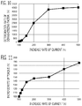
- FIG. 10 shows a demagnetizing factor when the supply current to the normal set of the windings is increased more than the normal time at the time of abnormality occurrence, in the surface magnet type motor of 10 poles 12 slots of Embodiment 5 described below.
- the horizontal axis of FIG. 10 shows an increase rate of current at the abnormal time to current at the normal time (current at the abnormal time/current at the normal time ⁇ 100%).
- the vertical axis of FIG. 10 shows a deterioration rate of irreversible demagnetizing factor at the abnormal time to irreversible demagnetizing factor at the normal time (demagnetizing factor at the abnormal time/demagnetizing factor at the normal time ⁇ 100%).
- the demagnetizing factor at the normal time is within the range from 0.
- the demagnetizing factor at the normal time is 1%
- the irreversible demagnetizing factor at the abnormal time becomes 10% at 1000% of the deterioration rate of the demagnetizing factor
- the irreversible demagnetizing factor at the abnormal time becomes 50% at 5000% of the deterioration rate of the demagnetizing factor.
- the increase rate of current increases
- the demagnetizing factor at the abnormal time increases; and when the increase rate of current increases more than 300%, the deterioration rate of the demagnetizing factor becomes almost constant.
- FIG. 11 shows an increase rate of torque in the case of FIG. 10 .
- the horizontal axis of FIG. 11 shows the increase rate of current at the abnormal time to the current at the normal time, as well as the horizontal axis of FIG. 10 .
- the vertical axis of FIG. 11 shows an increase rate of torque of the electric motor 2 at the abnormal time to torque of the electric motor 2 at the time when abnormality occurs and the increase rate of current is 100% (torque at the abnormal time/torque at the time of abnormal and 100% increase rate of current ⁇ 100%).
- the deterioration rate of the demagnetizing factor of FIG. 10 is deteriorated as the increase rate of current increases, the part of permanent magnet where the irreversible demagnetization does not cause increases output torque. Therefore, for example, since the increase rate of torque exceeds 140% at 200% of the increase rate of current, 70% of the torque at the normal time can be outputted. If 70% of the torque at the normal time can be outputted, most of steering by the driver can be covered.
- the motor current control units 40 a and 40 b increase up to an irreversible current that torque of the electric motor 2 does not drop by an excessive increase of the volume of magnet which irreversible demagnetization causes by increase in the supply current.
- the motor current control units 40 a and 40 b upper-limit the supply current to the normal set of the windings which is increased at the time of abnormality occurrence by a preliminarily set upper limit irreversible current.
- the upper limit irreversible current is preliminarily set to a supply current in which torque of the electric motor 2 becomes the maximum to the increase in the supply current, by a balance between a characteristic that the volume of magnet which irreversible demagnetization causes increases as the supply current increases, and a characteristic that torque of the electric motor 2 increases as the supply current increases.
- the supply current to the normal set of the windings is increased more than the normal time at the time of abnormality occurrence, heating amount of the normal set of the windings and the switching devices increase more than the normal time.
- the supply current can be increased up to the irreversible current continuously.
- the electric motor control system 1 according to Embodiment 2 will be explained. The explanation for constituent parts the same as those in Embodiment 1 will be omitted.
- the basic configuration of the electric motor control system 1 according to the present embodiment is the same as that of Embodiment 1; however, Embodiment 2 is different from Embodiment 1 in that the supply current to the normal set of the windings is increased considering the cooling performance of the electric motor 2 .
- the electric motor 2 does not have enough cooling performance for increase in heating amount of the normal set of the windings at the time of abnormality occurrence. Therefore, if the supply current is increased up to irreversible current continuously, temperature of the normal set of the windings rises too much, and there is a possibility of exceeding allowable temperature. Then, when abnormality occurs, after increasing the supply current to the normal set of the windings up to irreversible current, the motor current control units 40 a and 40 b decrease gradually.
- a winding temperature of the normal set can be prevented from rising too much by increasing the supply current up to irreversible current continuously.
- the motor current control units 40 a and 40 b upper-limit supply current (current command) of the normal set of the windings, which is set according to the assist torque, by an upper limit current.
- An initial value of the upper limit current is set to irreversible current, such as the upper limit irreversible current mentioned above, for example.
- the motor current control units 40 a and 40 b decrease the upper limit current gradually to a preliminarily set final value with a preliminarily set slope.
- the determination period can limit a period in which the supply current of the normal set is increased, and the winding temperature of the normal set can be prevented from rising too much. Since the supply current of the normal set decreases gradually forcibly after the determination period elapses, rapid deterioration of steering performance can be prevented.
- the motor current control units 40 a and 40 b permit increasing up to irreversible current again.
- the motor current control units 40 a and 40 b return the upper limit current to the initial values, such as the upper limit irreversible current, and permit increasing the supply current to the normal set of the windings up to irreversible current.
- the electric motor control system 1 according to Embodiment 3 will be explained. The explanation for constituent parts the same as those in Embodiment 1 will be omitted.
- the basic configuration of the electric motor control system 1 according to the present embodiment is the same as that of Embodiment 1; however, Embodiment 3 is different from Embodiment 1 in that the supply current to the normal set of the windings is increased considering the cooling performance of the electric motor 2 .
- the electric motor 2 according to the present embodiment does not have enough cooling performance for increase in heating amount of the normal set of the windings at the time of abnormality occurrence, as is the case with Embodiment 2.
- the motor current control units 40 a and 40 b prohibit increasing up to irreversible current again. According to this configuration, by prohibiting increasing up to irreversible current again, it is not necessary to decrease the supply current again after increase in the supply current of the normal set of the windings, and continuous assistance by half assist torque can be performed.
- the motor current control units 40 a and 40 b upper-limit the supply current (current command) of the normal set of the windings, which is set according to the assist torque, by the upper limit current, as is the case with Embodiment 2 mentioned above.
- the initial value of the upper limit current is set to irreversible current, such as the upper limit irreversible current mentioned above, for example.
- the motor current control units 40 a and 40 b decrease the upper limit current gradually up to a preliminarily set final value with a preliminarily set slope. Then, after decreasing the upper limit current up to the final value, the motor current control units 40 a and 40 b sets the upper limit current to the maximum current at the normal time.
- the electric motor control system 1 according to Embodiment 4 will be explained. The explanation for constituent parts the same as those in Embodiment 1 will be omitted.
- the basic configuration of the electric motor control system 1 according to the present embodiment is the same as that of Embodiment 1; however, Embodiment 4 is different from Embodiment 1 in processing after the electric motor control system 1 stops.
- the motor current control units 40 a and 40 b do not restart the electric motor control system 1 again, after the electric motor control system 1 stops once.
- the supply current to the normal set of the windings is increased up to irreversible current at the time of abnormality occurrence, magnetic force of the permanent magnet drops by irreversible demagnetization.
- the steering assistance by the electric motor control system 1 is performed until the vehicle stops at place where vehicle check and maintenance are possible, the ignition switch 7 is turned off, and the electric motor control system 1 stops. After that, the steering assistance by the electric motor 2 is not performed since abnormality occurs in the system and the magnetic force of the permanent magnet drops.
- Embodiment 5 The electric motor control system 1 according to Embodiment 5 will be explained. The explanation for constituent parts the same as those in Embodiment 1 will be omitted.
- the basic configuration of the electric motor control system 1 according to the present embodiment is the same as that of Embodiment 1; however, Embodiment 5 is different from Embodiment 1 in that the control circuit 4 is constituted by one CPU, and in the winding method.
- a schematic configuration diagram of the electric motor control system 1 in FIG. 6 it is a processing circuit configuration in which the first set of control system and the second set of control system were unified.
- the control circuit 4 is provided with one arithmetic processor 10 (CPU) and storage apparatus 17 for the arithmetic processor 10 .
- the first motor current control unit 40 a and the second motor current control unit 40 b can transmit information with each other inside the arithmetic processor 10 .
- the control circuit 4 is provided with a first driving circuit 11 a for the first motor current control unit 40 a , and a second driving circuit 11 b for the second motor current control unit 40 b .
- the input circuit 12 is commonly used for the first arithmetic processor 10 a and the second arithmetic processor 10 b .
- the control circuit 4 is provided with the common informing device driving circuit 16 for driving an informing device 15 .
- FIG. 7 shows a cross-sectional view cut by a plane perpendicular to an axial direction of the electric motor 2 according to the present embodiment.
- the stator 20 is constituted by laminating thin steel plates in which a plurality of slots 21 (in this example, 12 slots) (teeth) are arranged circumferentially.
- the rotor 23 is concentrically arranged in the radial-direction inner side of this stator 20 .
- the permanent magnets 22 are arranged in order of N pole and S pole in the peripheral direction (in this example, 10 poles).
- the winding of one phase is wound around each tooth of the stator 20 .
- Each of the first set of windings and the second set of windings is wound around tooth adjacent to each other.
- the winding of first set of U phase (U 1 ) is wound around a predetermined tooth, and then is wound around the 6th tooth.
- the winding of the second set of U phase (U 2 ) is wound; around the tooth adjacent to U 2 , the winding of the first set of V phase (V 1 ) is wound; around the tooth adjacent to V 1 , the winding of the second set of V phase (V 2 ) is wound; around the tooth adjacent to V 2 , the winding of the first set of W phase (W 1 ) is wound; and around the tooth adjacent to W 1 , the winding of the second set of W phase (W 2 ) is wound.
- the windings are wound regularly.
- 2 sets of the windings are alternately wound in the peripheral direction, and are concentrated winding with a preliminarily set phase difference (in this example, 30 degrees).
- each set of windings are connected so that the end of each phase winding becomes star connection.
- 2 sets of the windings are distributed in the peripheral direction of one stator, it may be so-called a tandem type motor which arranges a stator equipped with the first set of windings and a stator equipped with the second set of windings in series for one rotor.
- the electric motor control system 1 according to Embodiment 6 will be explained. The explanation for constituent parts the same as those in Embodiment 1 will be omitted.
- the basic configuration of the electric motor control system 1 according to the present embodiment is the same as that of Embodiment 1; however, Embodiment 6 is different from Embodiment 1 in the winding method,
- FIG. 9 shows a cross-sectional view cut by a plane perpendicular to an axial direction of the electric motor 2 according to the present embodiment. It is concentrated winding of 10 poles 12 slots, as is the case with Embodiment 5. However, unlike Embodiment 5, it is concentrated winding in which 2 sets of the windings are divided into two in a peripheral direction and wound. The first set of windings is wound around six teeth of the left-hand side in FIG. 9 , and the second set of windings is wound around six teeth of the right-hand side in FIG. 9 .
- the whole stator 20 was divided into two in the peripheral direction and each was distributed to each set of the windings, the whole stator 20 may be divided into four in the peripheral direction and each may be distributed to each set of the windings. It may be delta connection.
- Embodiment 7 The electric motor control system 1 according to Embodiment 7 will be explained. The explanation for constituent parts the same as those in Embodiment 1 will be omitted.
- the basic configuration of the electric motor control system 1 according to the present embodiment is the same as that of Embodiment 1; however, Embodiment 7 is different from Embodiment 1 in a setting method of conduction phase at the time of abnormality occurrence.
- the motor current control units 40 a and 40 b set conduction phase to a phase in which torque becomes the maximum, That is, the maximum torque current control is performed also at the time of abnormality occurrence.
- Conduction states to each set of the windings are different between the normal time and the time of abnormality occurrence. But, by setting to the current phase in which torque becomes the maximum at both times, the assist torque of the electric motor 2 can be increased to the maximum degree also at the time of abnormality occurrence.
- each set of the windings uses a winding in which resin layer is formed on its surface, According to this configuration, when the supply current to the normal set of the windings is increased up to irreversible current, a temperature rise of winding can be suppressed,
- the present disclosure can be preferably used for an electric motor control system including an electric motor which is provided with a stator equipped with 2 sets of plural phase windings and a rotor equipped with a permanent magnet and drives a steering mechanism of a vehicle, and a controller which controls the electric motor, and an electric power steering apparatus therewith.
Landscapes
- Engineering & Computer Science (AREA)
- Power Engineering (AREA)
- Chemical & Material Sciences (AREA)
- Combustion & Propulsion (AREA)
- Transportation (AREA)
- Mechanical Engineering (AREA)
- Control Of Ac Motors In General (AREA)
- Power Steering Mechanism (AREA)
- Steering Control In Accordance With Driving Conditions (AREA)
- Control Of Motors That Do Not Use Commutators (AREA)
Abstract
Description
Claims (12)
Applications Claiming Priority (1)
| Application Number | Priority Date | Filing Date | Title |
|---|---|---|---|
| PCT/JP2016/057965 WO2017158681A1 (en) | 2016-03-14 | 2016-03-14 | Electric motor control system and electric power steering device equipped with same |
Publications (2)
| Publication Number | Publication Date |
|---|---|
| US20190023315A1 US20190023315A1 (en) | 2019-01-24 |
| US11001297B2 true US11001297B2 (en) | 2021-05-11 |
Family
ID=59850865
Family Applications (1)
| Application Number | Title | Priority Date | Filing Date |
|---|---|---|---|
| US16/070,341 Active 2036-05-24 US11001297B2 (en) | 2016-03-14 | 2016-03-14 | Electric motor control system and electric power steering apparatus therewith |
Country Status (5)
| Country | Link |
|---|---|
| US (1) | US11001297B2 (en) |
| EP (1) | EP3431366B1 (en) |
| JP (1) | JP6472570B2 (en) |
| CN (1) | CN108778896B (en) |
| WO (1) | WO2017158681A1 (en) |
Cited By (1)
| Publication number | Priority date | Publication date | Assignee | Title |
|---|---|---|---|---|
| US20230142843A1 (en) * | 2020-04-14 | 2023-05-11 | Mando Corporation | Steering-assisting device |
Families Citing this family (24)
| Publication number | Priority date | Publication date | Assignee | Title |
|---|---|---|---|---|
| JP6533754B2 (en) * | 2016-03-17 | 2019-06-19 | 日立オートモティブシステムズ株式会社 | Electronic control device and control method thereof |
| CN109496190B (en) * | 2016-07-20 | 2020-01-21 | 日本精工株式会社 | Electric power steering apparatus |
| WO2018016356A1 (en) * | 2016-07-20 | 2018-01-25 | 日本精工株式会社 | Electric power steering device |
| JP6747329B2 (en) * | 2017-02-10 | 2020-08-26 | 株式会社デンソー | Rotating electric machine control device |
| KR20180095355A (en) * | 2017-02-17 | 2018-08-27 | 주식회사 만도 | Apparatus and method for controlling motor output during failure |
| KR101991257B1 (en) * | 2017-10-27 | 2019-06-21 | 주식회사 만도 | Control apparatus for dual winding motor and method thereof |
| KR102518904B1 (en) * | 2018-06-29 | 2023-04-06 | 에이치엘만도 주식회사 | Apparatus and method for controlling motor for vehicle |
| EP3826168A4 (en) * | 2018-07-19 | 2022-08-03 | Robert Bosch GmbH | ENGINE AND ASSOCIATED CONTROL METHOD |
| JP7230488B2 (en) * | 2018-12-21 | 2023-03-01 | 株式会社ジェイテクト | motor controller |
| US11479291B2 (en) * | 2018-12-27 | 2022-10-25 | Denso Corporation | Control apparatus |
| JP7346993B2 (en) * | 2018-12-27 | 2023-09-20 | 株式会社デンソー | Control device |
| KR102637909B1 (en) * | 2019-01-23 | 2024-02-19 | 에이치엘만도 주식회사 | Redundancy circuit for electric power steering system |
| KR102693162B1 (en) * | 2019-03-14 | 2024-08-08 | 에이치엘만도 주식회사 | System for assisting steering, Apparatus for controlling steering and Method thereof |
| JP7205352B2 (en) * | 2019-04-02 | 2023-01-17 | 株式会社デンソー | Rotating electric machine control device and electric power steering device using the same |
| JP7280099B2 (en) * | 2019-04-19 | 2023-05-23 | 株式会社ジェイテクト | Motor control system and motor control device |
| JP7243519B2 (en) | 2019-08-15 | 2023-03-22 | 株式会社デンソー | Rotating electric machine controller |
| CN112441108B (en) * | 2019-08-30 | 2022-04-01 | 广州汽车集团股份有限公司 | Motor control device, fault control method, vehicle steering system and vehicle |
| JP7255439B2 (en) * | 2019-10-01 | 2023-04-11 | 株式会社デンソー | Rotating body drive system |
| US11231297B2 (en) | 2020-01-09 | 2022-01-25 | Robert Bosch Gmbh | Providing availability of rotary position sensor information after hardware failures |
| CN112234903A (en) * | 2020-09-30 | 2021-01-15 | 环旭电子股份有限公司 | Vehicle driving apparatus and method thereof |
| US11942887B2 (en) * | 2021-12-02 | 2024-03-26 | Dana Tm4 Italia S.R.L. | Dual segmented motor drive |
| EP4274091A1 (en) * | 2022-05-06 | 2023-11-08 | Volvo Car Corporation | Method for operating an electric drive unit, data processing device and electric drive unit |
| KR102807645B1 (en) * | 2023-01-30 | 2025-05-19 | 에이치엘만도 주식회사 | Apparatus and method for steering control |
| SE547648C2 (en) * | 2023-11-10 | 2025-11-04 | Chassis Autonomy Sba Ab | Dual-Motor Steer-by-Wire Steering Assembly |
Citations (16)
| Publication number | Priority date | Publication date | Assignee | Title |
|---|---|---|---|---|
| US5969919A (en) * | 1997-09-16 | 1999-10-19 | Honda Giken Kogyo Kabushiki Kaisha | Drive unit for electric motor |
| WO2004010562A1 (en) | 2002-07-22 | 2004-01-29 | Nsk Ltd. | Motor, method of manufacturing motor, and driving control device for motor |
| US20060138883A1 (en) * | 2004-12-28 | 2006-06-29 | Hitachi, Ltd. | Motor for electric power steering and method for manufacturing the same |
| JP2006223037A (en) | 2005-02-09 | 2006-08-24 | Yaskawa Electric Corp | Motor control device and control method thereof |
| US20110074333A1 (en) | 2009-09-30 | 2011-03-31 | Denso Corporation | Control apparatus for multi-phase rotary machine and electric power steering system |
| US20110156629A1 (en) * | 2009-12-25 | 2011-06-30 | Denso Corporation | Electric power steering device |
| US20110315470A1 (en) | 2010-06-24 | 2011-12-29 | Denso Corporation | Motor drive apparatus and method, and electric power steering system using the same |
| JP2013038950A (en) | 2011-08-09 | 2013-02-21 | Denso Corp | Three-phase rotary machine control device |
| US20130200827A1 (en) * | 2012-02-07 | 2013-08-08 | Mitsubishi Electric Corporation | Motor control device, current control method applied to motor control device, and electric power steering device using motor control device |
| US8569981B2 (en) * | 2009-12-25 | 2013-10-29 | Denso Corporation | Motor drive and electric power steering apparatus using the same |
| US20140009093A1 (en) | 2012-07-04 | 2014-01-09 | Denso Corporation | Controller for multiple-phase rotating machine |
| US20140062362A1 (en) * | 2012-09-06 | 2014-03-06 | Fanuc Corporation | Control device of permanent magnet synchronous motor for preventing irreversible demagnetization of permanent magnet and control system including the same |
| US20150130329A1 (en) * | 2012-05-25 | 2015-05-14 | Yoshichika Kawashima | Electric motor |
| US20160065027A1 (en) * | 2014-08-29 | 2016-03-03 | Denso Corporation | Electric rotating machine |
| US20180062556A1 (en) * | 2015-03-12 | 2018-03-01 | Hitachi Automotive Systems, Ltd. | Drive Control Unit for Motor |
| US20190052218A1 (en) * | 2016-03-02 | 2019-02-14 | Hitachi Automotive Systems, Ltd. | Motor Driving Device |
Family Cites Families (2)
| Publication number | Priority date | Publication date | Assignee | Title |
|---|---|---|---|---|
| JP5449429B2 (en) * | 2012-02-24 | 2014-03-19 | 三菱電機株式会社 | AC rotating machine control device and method, and electric power steering device |
| JP6015693B2 (en) * | 2014-03-07 | 2016-10-26 | 株式会社デンソー | Control device and electric power steering device using the same |
-
2016
- 2016-03-14 JP JP2018505070A patent/JP6472570B2/en active Active
- 2016-03-14 US US16/070,341 patent/US11001297B2/en active Active
- 2016-03-14 EP EP16894305.8A patent/EP3431366B1/en active Active
- 2016-03-14 CN CN201680083278.7A patent/CN108778896B/en active Active
- 2016-03-14 WO PCT/JP2016/057965 patent/WO2017158681A1/en not_active Ceased
Patent Citations (22)
| Publication number | Priority date | Publication date | Assignee | Title |
|---|---|---|---|---|
| US5969919A (en) * | 1997-09-16 | 1999-10-19 | Honda Giken Kogyo Kabushiki Kaisha | Drive unit for electric motor |
| WO2004010562A1 (en) | 2002-07-22 | 2004-01-29 | Nsk Ltd. | Motor, method of manufacturing motor, and driving control device for motor |
| US20050189828A1 (en) | 2002-07-22 | 2005-09-01 | Nsk Ltd. | Motor, method for manufacturing motor, and motor drive controller |
| US20060138883A1 (en) * | 2004-12-28 | 2006-06-29 | Hitachi, Ltd. | Motor for electric power steering and method for manufacturing the same |
| JP2006223037A (en) | 2005-02-09 | 2006-08-24 | Yaskawa Electric Corp | Motor control device and control method thereof |
| US20110074333A1 (en) | 2009-09-30 | 2011-03-31 | Denso Corporation | Control apparatus for multi-phase rotary machine and electric power steering system |
| JP2011078230A (en) | 2009-09-30 | 2011-04-14 | Denso Corp | Control apparatus for multi-phase rotary machine and electric power steering system using the same |
| US20110156629A1 (en) * | 2009-12-25 | 2011-06-30 | Denso Corporation | Electric power steering device |
| US8569981B2 (en) * | 2009-12-25 | 2013-10-29 | Denso Corporation | Motor drive and electric power steering apparatus using the same |
| US8528689B2 (en) * | 2010-06-24 | 2013-09-10 | Denso Corporation | Motor drive apparatus and method, and electric power steering system using the same |
| US20110315470A1 (en) | 2010-06-24 | 2011-12-29 | Denso Corporation | Motor drive apparatus and method, and electric power steering system using the same |
| JP2012025374A (en) | 2010-06-24 | 2012-02-09 | Denso Corp | Motor drive apparatus, and electric power steering system using the same |
| JP2013038950A (en) | 2011-08-09 | 2013-02-21 | Denso Corp | Three-phase rotary machine control device |
| US20130200827A1 (en) * | 2012-02-07 | 2013-08-08 | Mitsubishi Electric Corporation | Motor control device, current control method applied to motor control device, and electric power steering device using motor control device |
| US20150130329A1 (en) * | 2012-05-25 | 2015-05-14 | Yoshichika Kawashima | Electric motor |
| US20140009093A1 (en) | 2012-07-04 | 2014-01-09 | Denso Corporation | Controller for multiple-phase rotating machine |
| JP2014014240A (en) | 2012-07-04 | 2014-01-23 | Denso Corp | Controller of multiphase rotary machine |
| US9257930B2 (en) * | 2012-07-04 | 2016-02-09 | Denso Corporation | Controller for multiple-phase rotating machine |
| US20140062362A1 (en) * | 2012-09-06 | 2014-03-06 | Fanuc Corporation | Control device of permanent magnet synchronous motor for preventing irreversible demagnetization of permanent magnet and control system including the same |
| US20160065027A1 (en) * | 2014-08-29 | 2016-03-03 | Denso Corporation | Electric rotating machine |
| US20180062556A1 (en) * | 2015-03-12 | 2018-03-01 | Hitachi Automotive Systems, Ltd. | Drive Control Unit for Motor |
| US20190052218A1 (en) * | 2016-03-02 | 2019-02-14 | Hitachi Automotive Systems, Ltd. | Motor Driving Device |
Non-Patent Citations (4)
| Title |
|---|
| Communication dated May 26, 2020, from the State Intellectual Property Office of the P.R. of China in Application No. 201680083278.7. |
| Communication dated Nov. 6, 2018, from the Japanese Patent Office in counterpart application No. 2018-505070. |
| Extended European Search Report dated Feb. 27, 2019 issued by the European Patent Office in application No. 16894305.8. |
| International Search Report for PCT/JP2016/057965 dated May 31, 2016 [PCT/ISA/210]. |
Cited By (2)
| Publication number | Priority date | Publication date | Assignee | Title |
|---|---|---|---|---|
| US20230142843A1 (en) * | 2020-04-14 | 2023-05-11 | Mando Corporation | Steering-assisting device |
| US12589795B2 (en) * | 2020-04-14 | 2026-03-31 | Hl Mando Corporation | Steering-assisting device |
Also Published As
| Publication number | Publication date |
|---|---|
| EP3431366B1 (en) | 2019-10-23 |
| WO2017158681A1 (en) | 2017-09-21 |
| CN108778896B (en) | 2021-01-01 |
| EP3431366A1 (en) | 2019-01-23 |
| JPWO2017158681A1 (en) | 2018-05-24 |
| US20190023315A1 (en) | 2019-01-24 |
| EP3431366A4 (en) | 2019-03-27 |
| CN108778896A (en) | 2018-11-09 |
| JP6472570B2 (en) | 2019-02-20 |
Similar Documents
| Publication | Publication Date | Title |
|---|---|---|
| US11001297B2 (en) | Electric motor control system and electric power steering apparatus therewith | |
| EP3210849B1 (en) | Electric power steering device | |
| JP5168307B2 (en) | Electric motor control device | |
| US10644642B2 (en) | Three phase duplexing motor for electric power steering apparatus | |
| US11018611B2 (en) | Control apparatus for multi-phase rotating electric machine | |
| WO2014141342A1 (en) | Motor control device, and electric power steering device and vehicle using same | |
| US11070158B2 (en) | Rotary electric machine control apparatus | |
| US10720873B2 (en) | Electric drive device and control method for same | |
| WO2014136166A1 (en) | Motor control device, electric power steering device using same, and vehicle | |
| US11190124B2 (en) | Motor control method, power conversion device, motor module, and electric power steering device | |
| US10298165B2 (en) | Rotary electric machine system | |
| JP2016019330A (en) | Controller of rotary machine | |
| US11554805B2 (en) | Vehicle control apparatus | |
| CN110463026A (en) | Electric power steering | |
| JP2017077048A (en) | Dynamo-electric machine controller, and electric power steering device using the same | |
| CN101193787A (en) | electric steering system | |
| US20260088745A1 (en) | Rotary electric machine control device |
Legal Events
| Date | Code | Title | Description |
|---|---|---|---|
| AS | Assignment |
Owner name: MITSUBISHI ELECTRIC CORPORATION, JAPAN Free format text: ASSIGNMENT OF ASSIGNORS INTEREST;ASSIGNORS:TAKIZAWA, YUJI;AKUTSU, SATORU;ASAO, YOSHIHITO;SIGNING DATES FROM 20180605 TO 20180606;REEL/FRAME:046358/0222 |
|
| FEPP | Fee payment procedure |
Free format text: ENTITY STATUS SET TO UNDISCOUNTED (ORIGINAL EVENT CODE: BIG.); ENTITY STATUS OF PATENT OWNER: LARGE ENTITY |
|
| STPP | Information on status: patent application and granting procedure in general |
Free format text: DOCKETED NEW CASE - READY FOR EXAMINATION |
|
| STPP | Information on status: patent application and granting procedure in general |
Free format text: NON FINAL ACTION MAILED |
|
| STPP | Information on status: patent application and granting procedure in general |
Free format text: RESPONSE TO NON-FINAL OFFICE ACTION ENTERED AND FORWARDED TO EXAMINER |
|
| STPP | Information on status: patent application and granting procedure in general |
Free format text: FINAL REJECTION MAILED |
|
| STPP | Information on status: patent application and granting procedure in general |
Free format text: ADVISORY ACTION MAILED |
|
| STCV | Information on status: appeal procedure |
Free format text: NOTICE OF APPEAL FILED |
|
| STPP | Information on status: patent application and granting procedure in general |
Free format text: NOTICE OF ALLOWANCE MAILED -- APPLICATION RECEIVED IN OFFICE OF PUBLICATIONS |
|
| STPP | Information on status: patent application and granting procedure in general |
Free format text: NOTICE OF ALLOWANCE MAILED -- APPLICATION RECEIVED IN OFFICE OF PUBLICATIONS |
|
| STPP | Information on status: patent application and granting procedure in general |
Free format text: PUBLICATIONS -- ISSUE FEE PAYMENT RECEIVED |
|
| STPP | Information on status: patent application and granting procedure in general |
Free format text: PUBLICATIONS -- ISSUE FEE PAYMENT VERIFIED |
|
| STCF | Information on status: patent grant |
Free format text: PATENTED CASE |
|
| AS | Assignment |
Owner name: MITSUBISHI ELECTRIC MOBILITY CORPORATION, JAPAN Free format text: COMPANY SPLIT;ASSIGNOR:MITSUBISHI ELECTRIC CORPORATION;REEL/FRAME:068834/0585 Effective date: 20240401 |
|
| MAFP | Maintenance fee payment |
Free format text: PAYMENT OF MAINTENANCE FEE, 4TH YEAR, LARGE ENTITY (ORIGINAL EVENT CODE: M1551); ENTITY STATUS OF PATENT OWNER: LARGE ENTITY Year of fee payment: 4 |