JP6747329B2 - Rotating electric machine control device - Google Patents
Rotating electric machine control device Download PDFInfo
- Publication number
- JP6747329B2 JP6747329B2 JP2017023439A JP2017023439A JP6747329B2 JP 6747329 B2 JP6747329 B2 JP 6747329B2 JP 2017023439 A JP2017023439 A JP 2017023439A JP 2017023439 A JP2017023439 A JP 2017023439A JP 6747329 B2 JP6747329 B2 JP 6747329B2
- Authority
- JP
- Japan
- Prior art keywords
- power supply
- abnormality
- relay
- electric machine
- power
- Prior art date
- Legal status (The legal status is an assumption and is not a legal conclusion. Google has not performed a legal analysis and makes no representation as to the accuracy of the status listed.)
- Active
Links
Images


Classifications
-
- H—ELECTRICITY
- H02—GENERATION; CONVERSION OR DISTRIBUTION OF ELECTRIC POWER
- H02P—CONTROL OR REGULATION OF ELECTRIC MOTORS, ELECTRIC GENERATORS OR DYNAMO-ELECTRIC CONVERTERS; CONTROLLING TRANSFORMERS, REACTORS OR CHOKE COILS
- H02P29/00—Arrangements for regulating or controlling electric motors, appropriate for both AC and DC motors
- H02P29/02—Providing protection against overload without automatic interruption of supply
- H02P29/024—Detecting a fault condition, e.g. short circuit, locked rotor, open circuit or loss of load
-
- B—PERFORMING OPERATIONS; TRANSPORTING
- B62—LAND VEHICLES FOR TRAVELLING OTHERWISE THAN ON RAILS
- B62D—MOTOR VEHICLES; TRAILERS
- B62D5/00—Power-assisted or power-driven steering
- B62D5/04—Power-assisted or power-driven steering electrical, e.g. using an electric servo-motor connected to, or forming part of, the steering gear
- B62D5/0403—Power-assisted or power-driven steering electrical, e.g. using an electric servo-motor connected to, or forming part of, the steering gear characterised by constructional features, e.g. common housing for motor and gear box
-
- B—PERFORMING OPERATIONS; TRANSPORTING
- B62—LAND VEHICLES FOR TRAVELLING OTHERWISE THAN ON RAILS
- B62D—MOTOR VEHICLES; TRAILERS
- B62D5/00—Power-assisted or power-driven steering
- B62D5/04—Power-assisted or power-driven steering electrical, e.g. using an electric servo-motor connected to, or forming part of, the steering gear
- B62D5/0409—Electric motor acting on the steering column
- B62D5/0412—Electric motor acting on the steering column the axes of motor and steering column being parallel
-
- B—PERFORMING OPERATIONS; TRANSPORTING
- B62—LAND VEHICLES FOR TRAVELLING OTHERWISE THAN ON RAILS
- B62D—MOTOR VEHICLES; TRAILERS
- B62D5/00—Power-assisted or power-driven steering
- B62D5/04—Power-assisted or power-driven steering electrical, e.g. using an electric servo-motor connected to, or forming part of, the steering gear
- B62D5/0457—Power-assisted or power-driven steering electrical, e.g. using an electric servo-motor connected to, or forming part of, the steering gear characterised by control features of the drive means as such
- B62D5/046—Controlling the motor
- B62D5/0463—Controlling the motor calculating assisting torque from the motor based on driver input
-
- B—PERFORMING OPERATIONS; TRANSPORTING
- B62—LAND VEHICLES FOR TRAVELLING OTHERWISE THAN ON RAILS
- B62D—MOTOR VEHICLES; TRAILERS
- B62D5/00—Power-assisted or power-driven steering
- B62D5/04—Power-assisted or power-driven steering electrical, e.g. using an electric servo-motor connected to, or forming part of, the steering gear
- B62D5/0457—Power-assisted or power-driven steering electrical, e.g. using an electric servo-motor connected to, or forming part of, the steering gear characterised by control features of the drive means as such
- B62D5/0481—Power-assisted or power-driven steering electrical, e.g. using an electric servo-motor connected to, or forming part of, the steering gear characterised by control features of the drive means as such monitoring the steering system, e.g. failures
- B62D5/0484—Power-assisted or power-driven steering electrical, e.g. using an electric servo-motor connected to, or forming part of, the steering gear characterised by control features of the drive means as such monitoring the steering system, e.g. failures for reaction to failures, e.g. limp home
-
- B—PERFORMING OPERATIONS; TRANSPORTING
- B62—LAND VEHICLES FOR TRAVELLING OTHERWISE THAN ON RAILS
- B62D—MOTOR VEHICLES; TRAILERS
- B62D5/00—Power-assisted or power-driven steering
- B62D5/04—Power-assisted or power-driven steering electrical, e.g. using an electric servo-motor connected to, or forming part of, the steering gear
- B62D5/0457—Power-assisted or power-driven steering electrical, e.g. using an electric servo-motor connected to, or forming part of, the steering gear characterised by control features of the drive means as such
- B62D5/0481—Power-assisted or power-driven steering electrical, e.g. using an electric servo-motor connected to, or forming part of, the steering gear characterised by control features of the drive means as such monitoring the steering system, e.g. failures
- B62D5/0493—Power-assisted or power-driven steering electrical, e.g. using an electric servo-motor connected to, or forming part of, the steering gear characterised by control features of the drive means as such monitoring the steering system, e.g. failures detecting processor errors, e.g. plausibility of steering direction
-
- H—ELECTRICITY
- H02—GENERATION; CONVERSION OR DISTRIBUTION OF ELECTRIC POWER
- H02P—CONTROL OR REGULATION OF ELECTRIC MOTORS, ELECTRIC GENERATORS OR DYNAMO-ELECTRIC CONVERTERS; CONTROLLING TRANSFORMERS, REACTORS OR CHOKE COILS
- H02P27/00—Arrangements or methods for the control of AC motors characterised by the kind of supply voltage
- H02P27/04—Arrangements or methods for the control of AC motors characterised by the kind of supply voltage using variable-frequency supply voltage, e.g. inverter or converter supply voltage
- H02P27/06—Arrangements or methods for the control of AC motors characterised by the kind of supply voltage using variable-frequency supply voltage, e.g. inverter or converter supply voltage using dc to ac converters or inverters
-
- H—ELECTRICITY
- H02—GENERATION; CONVERSION OR DISTRIBUTION OF ELECTRIC POWER
- H02P—CONTROL OR REGULATION OF ELECTRIC MOTORS, ELECTRIC GENERATORS OR DYNAMO-ELECTRIC CONVERTERS; CONTROLLING TRANSFORMERS, REACTORS OR CHOKE COILS
- H02P29/00—Arrangements for regulating or controlling electric motors, appropriate for both AC and DC motors
- H02P29/02—Providing protection against overload without automatic interruption of supply
- H02P29/024—Detecting a fault condition, e.g. short circuit, locked rotor, open circuit or loss of load
- H02P29/028—Detecting a fault condition, e.g. short circuit, locked rotor, open circuit or loss of load the motor continuing operation despite the fault condition, e.g. eliminating, compensating for or remedying the fault
Description
本発明は、回転電機制御装置、および、これを用いた電動パワーステアリング装置に関する。 The present invention relates to a rotary electric machine control device and an electric power steering device using the same.
従来、モータを駆動源とした電動パワーステアリング装置が知られている。例えば特許文献1では、他相における過大な電流偏差の発生を監視することにより異常判定を実行している。
Conventionally, an electric power steering device using a motor as a drive source is known. For example, in
特許文献1では、構成を簡素化すべく、過大な電流偏差の発生を監視することで異常判定を実行しており、電流偏差以外による異常判定については何ら言及されていない。
本発明は、上述の課題に鑑みてなされたものであり、その目的は、他系統の異常を適切に監視可能な回転電機制御装置、および、これを用いた電動パワーステアリング装置を提供することにある。
In
The present invention has been made in view of the above problems, and an object thereof is to provide a rotating electric machine control device capable of appropriately monitoring abnormality of another system, and an electric power steering device using the same. is there.
本発明の回転電機制御装置は、複数の巻線組(180、280)を有する回転電機(80)を制御するものであって、複数のインバータ回路(120、220)と、複数の電源リレー(121、221)と、複数の制御部(150、250)と、を備える。
インバータ回路は、巻線組ごとに対応して設けられる。
巻線組、および、巻線組に対応して設けられる構成の組み合わせを系統とする。電源リレーは、バッテリ(101、201)とインバータ回路との間の通電の断接を切り替え可能であって、系統ごとに設けられる。
The rotary electric machine control device of the present invention controls a rotary electric machine (80) having a plurality of winding groups (180, 280), and includes a plurality of inverter circuits (120, 220) and a plurality of power supply relays ( 121, 221) and a plurality of control units (150, 250).
The inverter circuit is provided corresponding to each winding set.
A system includes a winding set and a combination of configurations provided corresponding to the winding set. The power supply relay can switch connection and disconnection of energization between the battery (101, 201) and the inverter circuit, and is provided for each system.
制御部は、系統ごとに設けられる。制御部は、駆動制御部(151、251)、自系統監視部(152、252)、および、他系統監視部(153、253)を有する。
駆動制御部は、インバータ回路、および、電源リレーを制御する。
自系統監視部は、自身の系統である自系統の異常を監視する。
他系統監視部は、他の系統である他系統の異常を監視する。
The control unit is provided for each system. The control unit includes a drive control unit (151, 251), an own system monitoring unit (152, 252), and another system monitoring unit (153, 253).
The drive control unit controls the inverter circuit and the power supply relay.
The own system monitoring unit monitors an abnormality of its own system, which is its own system.
The other system monitoring unit monitors an abnormality in another system, which is another system.
駆動制御部は、給電停止を要する異常が自系統に生じた場合、自系統の電源リレーをオフにする。
第1の態様では、制御部は、通信により相互に送受信可能である。他系統監視部は、通信経路とは別途の信号線(31〜33、41〜43)を経由して、他系統の電源リレーの状態に係る電源リレー情報を直接的に取得し、電源リレー情報に基づいて他系統の異常を監視する。
第2の態様では、他系統監視部は、信号線(31〜33、41〜43)を経由して、他系統の電源リレーの状態に係る電源リレー情報を取得し、電源リレー情報に基づいて他系統の異常を監視する。他系統監視部は、起動時のイニシャルチェックにて、電源リレー情報に基づき、他系統の電源リレーの異常を判定する。
The drive control unit turns off the power relay of the own system when an abnormality that requires power supply stop occurs in the own system.
In the first aspect, the control units can mutually transmit and receive by communication. The other system monitoring unit directly obtains the power supply relay information related to the state of the power supply relay of the other system via the signal lines (31 to 33, 41 to 43) separate from the communication path, and the power supply relay information. The abnormality of other system is monitored based on .
In the second aspect, the other system monitoring unit acquires the power supply relay information regarding the state of the power supply relay of the other system via the signal lines (31 to 33, 41 to 43), and based on the power supply relay information. Monitor for abnormalities in other systems. The other system monitoring unit determines the abnormality of the power supply relay of the other system based on the power supply relay information in the initial check at startup.
制御部は、自系統監視部により、自系統の異常を監視しており、給電停止を要する異常が自系統に生じた場合、自系統のリレーをオフにする。すなわち、電源リレーは、自系統が正常であれば、オンされており、給電停止を要する異常が生じていればオフされる。したがって、他系統監視部は、他系統の電源リレーの状態に基づき、他系統の状態を監視可能である。これにより、他系統の異常を適切に監視することができる。 The control unit monitors the abnormality of the own system by the own system monitoring unit, and turns off the relay of the own system when the abnormality that requires the power supply stop occurs in the own system. That is, the power supply relay is turned on when its own system is normal, and is turned off when an abnormality requiring stopping the power supply occurs. Therefore, the other system monitoring unit can monitor the state of the other system based on the state of the power relay of the other system. Accordingly, it is possible to properly monitor the abnormality of the other system.
以下、本発明による回転電機制御装置を図面に基づいて説明する。以下、複数の実施形態において、実質的に同一の構成には同一の符号を付して説明を省略する。
(第1実施形態)
本発明の第1実施形態を図1〜図9に示す。
図1および図2に示すように、本実施形態の回転電機制御装置としてのモータ制御装置10は、回転電機としてのモータ80とともに、例えば車両のステアリング操作を補助するための電動パワーステアリング装置8に適用される。図中、モータ制御装置10を「ECU」と記載する。
Hereinafter, a rotary electric machine control device according to the present invention will be described with reference to the drawings. Hereinafter, in a plurality of embodiments, the substantially same configurations are denoted by the same reference numerals, and description thereof will be omitted.
(First embodiment)
1st Embodiment of this invention is shown in FIGS.
As shown in FIGS. 1 and 2, a
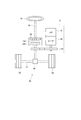
図1は、電動パワーステアリング装置8を備えるステアリングシステム90の構成を示す。ステアリングシステム90は、操舵部材であるステアリングホイール91、ステアリングシャフト92、ピニオンギア96、ラック軸97、車輪98、および、電動パワーステアリング装置8等を備える。
FIG. 1 shows a configuration of a
ステアリングホイール91は、ステアリングシャフト92と接続される。ステアリングシャフト92には、操舵トルクTsを検出するトルクセンサ94が設けられる。トルクセンサ94は、第1センサ部194および第2センサ部294を有しており、二重化されている。
ステアリングシャフト92の先端には、ピニオンギア96が設けられる。ピニオンギア96は、ラック軸97に噛み合っている。ラック軸97の両端には、タイロッド等を介して一対の車輪98が連結される。
The
A
運転者がステアリングホイール91を回転させると、ステアリングホイール91に接続されたステアリングシャフト92が回転する。ステアリングシャフト92の回転運動は、ピニオンギア96によってラック軸97の直線運動に変換される。一対の車輪98は、ラック軸97の変位量に応じた角度に操舵される。
When the driver rotates the
電動パワーステアリング装置8は、モータ80、モータ80の回転を減速してステアリングシャフト92に伝える動力伝達部としての減速ギア89、および、モータ制御装置10等を備える。すなわち、本実施形態の電動パワーステアリング装置8は、所謂「コラムアシストタイプ」であるが、モータ80の回転をラック軸97に伝える所謂「ラックアシストタイプ」等としてもよい。本実施形態では、ステアリングシャフト92が「駆動対象」に対応する。
The electric power steering device 8 includes a
モータ80は、運転者によるステアリングホイール91の操舵を補助する補助トルクを出力するものであって、電源であるバッテリ101、201から電力が供給されることにより駆動され、減速ギア89を正逆回転させる。モータ80は、3相ブラシレスモータであって、いずれも図示しないロータおよびステータを有する。図2に示すように、モータ80は、巻線組としての第1モータ巻線180および第2モータ巻線280を有する。図中、第1モータ巻線180を「モータ巻線1」、第2モータ巻線280を「モータ巻線2」とする。後述の他の構成についても、図中適宜、「第1」を添え字の「1」、「第2」を添え字の「2」として記載する。
The
以下、第1モータ巻線180、および、第1モータ巻線180に対応して設けられ、第1モータ巻線180の通電制御に係る第1インバータ回路120および第1制御部150等の組み合わせを第1系統L1とする。第2モータ巻線280、および、第2モータ巻線280に対応して設けられ、第2モータ巻線280の通電制御に係る第2インバータ回路220および第2制御部250等の組み合わせを第2系統L2とする。
以下、第1系統L1に係る構成を100番台で符番し、第2系統L2に係る構成を200番台で符番する。また、第1系統L1および第2系統L2において、同様の構成には、下2桁が同じとなるように符番する。
Hereinafter, a combination of the first motor winding 180 and the
Hereinafter, configurations related to the first system L1 are numbered in the 100s, and configurations related to the second system L2 are numbered in the 200s. Further, in the first system L1 and the second system L2, similar configurations are numbered so that the last two digits are the same.
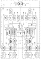
モータ制御装置10は、インバータ回路120、220、電源リレー121、221、および、制御部150、250等を備える。
モータ制御装置10には、コネクタ部105、205が設けられる。コネクタ部105には、電源コネクタ111、車両通信コネクタ112、および、トルクコネクタ113が含まれる。コネクタ部205には、電源コネクタ211、車両通信コネクタ212、および、トルクコネクタ213が含まれる。図2では、コネクタ部105、205が、それぞれ単一のコネクタとして形成されていてもよいし、複数のコネクタに分割されていてもよい。
The
The
第1電源コネクタ111は、第1バッテリ101に接続される。第1バッテリ101の電力は、電源コネクタ111、電源リレー121、インバータ回路120、および、モータリレー122を経由して、第1モータ巻線180に供給される。また、第1バッテリ101の電力は、第1制御部150および第1系統L1のセンサ類にも供給される。
第2電源コネクタ211は、第2バッテリ201に接続される。第2バッテリ201の電力は、電源コネクタ211、電源リレー221、インバータ回路220、および、モータリレー222を経由して、第2モータ巻線280に供給される。
電源コネクタ111、211は、同一のバッテリに接続され、系統L1、L2にてバッテリを共用していてもよい。
The first
The
The
第1車両通信コネクタ112は、車両通信網195に接続され、第2車両通信コネクタ212は、車両通信網295に接続される。車両通信コネクタ112、212は、同一の車両通信網に接続されてもよい。図2では、車両通信網195、295としてCAN(Controller Area Network)を例示しているが、CAN−FD(CAN with Flexible Data rate)やFlexRay等、どのような規格のものでもよい。
第1トルクコネクタ113は、トルクセンサ94の第1センサ部194と接続される。
第2トルクコネクタ213は、トルクセンサ94の第2センサ部294と接続される。
The first
The
The
第1インバータ回路120は、図示しないスイッチング素子を有する3相インバータであって、第1モータ巻線180へ供給される電力を変換する。第1インバータ回路120のスイッチング素子は、第1制御部150から出力される駆動信号に基づいてオンオフ作動が制御される。
第2インバータ回路220は、図示しないスイッチング素子を有する3相インバータであって、第2モータ巻線280へ供給される電力を変換する。第2インバータ回路220のスイッチング素子は、第2制御部250から出力される駆動信号に基づいてオンオフ作動が制御される。
The
The
第1電源リレー121は、第1電源コネクタ111と第1インバータ回路120との間に設けられる。第1電源リレー121は、第1制御部150により制御され、オンのときに第1バッテリ101側と第1インバータ回路120側との間の通電が許容され、オフのときに第1バッテリ101側と第1インバータ回路120側との通電が禁止される。
第2電源リレー221は、第2電源コネクタ211と第2インバータ回路220との間に設けられる。第2電源リレー221は、第2制御部250により制御され、オンのときに第2バッテリ201側と第2インバータ回路220側との間の通電が許容され、オフのときに第2バッテリ201側と第2インバータ回路220側との通電が禁止される。
The first
The second
本実施形態の電源リレー121、221は、MOSFET等の半導体リレーである。電源リレー121、221がMOSFETのように寄生ダイオードを有する場合、電源リレー121、221と寄生ダイオードの向きが逆向きになるように接続される図示しない逆接保護リレーを設けることが望ましい。また、電源リレー121、221は、メカリレーであってもよい。 The power supply relays 121 and 221 of this embodiment are semiconductor relays such as MOSFETs. When the power supply relays 121 and 221 have parasitic diodes like MOSFETs, it is desirable to provide a reverse connection protection relay (not shown) that is connected so that the power supply relays 121 and 221 and the parasitic diodes are in opposite directions. Further, the power relays 121 and 221 may be mechanical relays.
第1モータリレー122は、第1インバータ回路120と第1モータ巻線180との間の各相に設けられる。第1モータリレー122は、第1制御部150により制御され、オンのときに第1インバータ回路120側と第1モータ巻線180との間の通電が許容され、オフのときに第1インバータ回路120側と第1モータ巻線180との間の通電が禁止される。
第2モータリレー222は、第2インバータ回路220と第2モータ巻線280との間の各相に設けられる。第2モータリレー222は、第2制御部250により制御され、オンのときに第2インバータ回路220側と第2モータ巻線280との間の通電が許容され、オフのときに第2インバータ回路220側と第2モータ巻線280との間の通電が禁止される。
The
The
第1電流センサ125は、第1モータ巻線180の各相に通電される第1U相電流Iu1、第1V相電流Iv1、および、第1W相電流Iw1を検出し、検出値を第1制御部150に出力する。
第2電流センサ225は、第2モータ巻線280の各相に通電される第2U相電流Iu2、第2V相電流Iv2、および、第2W相電流Iw2を検出し、検出値を第2制御部250に出力する。
第1回転角センサ126は、モータ80の回転角を検出し、第1制御部150に出力する。第2回転角センサ226は、モータ80の回転角を検出し、第2制御部250に出力する。
The first
The second
The first
第1ドライバ回路140は、第1制御部150からの制御信号に基づき、第1インバータ回路120のスイッチング素子、第1電源リレー121、および、第1モータリレー122を駆動する信号を各素子に出力する。
第2ドライバ回路240は、第2制御部250からの制御信号に基づき、第2インバータ回路220のスイッチング素子、第1電源リレー221、および、第1モータリレー222を駆動する信号を各素子に出力する。
The
The
第1制御部150は、駆動制御部151、自系統監視部152、および、他系統監視部153を有する。第2制御部250は、駆動制御部251、自系統監視部252、および、他系統監視部253を有する。
制御部150、250は、マイコンを主体として構成される。制御部150、250における各処理は、ROM等の実体的なメモリ装置に予め記憶されたプログラムをCPUで実行することによるソフトウェア処理であってもよいし、専用の電子回路によるハードウェア処理であってもよい。
制御部150、250は、通信により、相互に情報を送受信可能である。以下適宜、制御部150、250間の通信を、「マイコン間通信」という。また、マイコン間通信にて他系統から取得された信号を「他系統信号」とする。
The
The
The
駆動制御部151は、インバータ回路120のスイッチング素子のオンオフ作動を制御するインバータ駆動信号を生成する。生成されたインバータ駆動信号に基づいてスイッチング素子がオンオフされることで、モータ80の駆動が制御される。
また、駆動制御部151は、電源リレー121を制御する電源リレー駆動信号Vrd1、および、モータリレー122を制御するモータリレー駆動信号を生成する。
The
The
駆動制御部251は、インバータ回路220のスイッチング素子のオンオフ作動を制御するインバータ駆動信号を生成する。生成されたインバータ駆動信号に基づいてスイッチング素子がオンオフされることで、モータ80の駆動が制御される。
また、駆動制御部251は、電源リレー221を制御する電源リレー駆動信号Vrd2、および、モータリレー222を制御するリレー制御信号を生成する。
The
The
駆動制御部151、251は、マイコン間通信により情報を共有する。
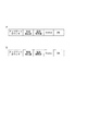
図3に示すように、マイコン間通信の通信フレームには、アップデートカウンタ、電流検出値、電流指令値、電流制限値、ステータス信号、および、誤り検出値信号であるCRC信号が含まれる。ビット数等は、適宜設定可能である。また、信号順は変更してもよいし、他の情報を追加してもよい。また、誤り検出信号は、例えばチェックサム信号等、CRC信号以外のものであってもよい。本実施形態では、電流検出値、電流指令値および電流制限値はdq軸の値とするが、3相の値等としてもよい。また、電流指令値に替えて、トルク指令値や電圧指令値としてもよい。
The
As shown in FIG. 3, the communication frame for inter-microcomputer communication includes an update counter, a current detection value, a current command value, a current limit value, a status signal, and a CRC signal which is an error detection value signal. The number of bits and the like can be set as appropriate. The signal order may be changed, or other information may be added. The error detection signal may be something other than the CRC signal, such as a checksum signal. In the present embodiment, the current detection value, the current command value, and the current limit value are dq-axis values, but may be three-phase values or the like. Further, a torque command value or a voltage command value may be used instead of the current command value.
制御部150、250では、マイコン間通信にて、電流検出値や電流指令値等を相互に送受信し、系統L1、L2を同期させてモータ80を駆動するように、協調制御を行う。
例えば、制御部150、250の一方のマスター、他方をスレーブとし、マスターからの指令に応じてスレーブを協調させるようにしてもよい。マスター側からスレーブ側へ送信される信号と、スレーブ側からマスター側へ送信される信号とは、同様であってもよいし、スレーブ側からマスター側への指令値の送信を省略してもよい。また、マスター側から送信される信号と、スレーブ側から送信される信号とが異なっていてもよい。例えば図4(a)に示すように、マスター側からスレーブ側へ送られる信号の通信フレームには、アップデートカウンタ、電流検出値、電流指令値、ステータス信号、および、CRC信号が含まれる。また、図4(b)に示すように、スレーブ側からマスター側へ送られる信号の通信フレームには、電流指令値に替えて、電流制限値が含まれる。複数の制御部をマスター側とスレーブ側とに分けて用いる場合、それぞれに必要な情報に絞って通信を行うことで、通信量を削減することができる。
また、系統L1、L2の電流の和と差を制御することで2系統を協調させるようにしてもよい。
The
For example, one of the
Alternatively, the two systems may be coordinated by controlling the sum and difference of the currents of the systems L1 and L2.
自系統監視部152は、自系統である第1系統L1内での異常を監視する。自系統内にて給電停止を要する異常が生じた場合、第1制御部150は、第1電源リレー121をオフにし、第1モータ巻線180への給電を停止する。
他系統監視部153は、第2制御部250からマイコン間通信にて取得された情報、および、第2電源リレー221の状態に基づき、他系統である第2系統L2の異常を監視する。本実施形態では、第1制御部150は、駆動制御部251から出力される第2電源リレー221の駆動に係る第2電源リレー駆動信号Vrd2を、信号線41を経由して取得し、第2電源リレー駆動信号Vrd2に基づいて第2電源リレー221の状態を監視する。
The own
The other
自系統監視部252は、自系統である第2系統L2内での異常を監視する。自系統内にて給電停止を要する異常が生じた場合、第2制御部250は、第2電源リレー221をオフにし、第2モータ巻線280への給電を停止する。
他系統監視部253は、第1制御部150からマイコン間通信にて取得された情報、および、第1電源リレー121の状態に基づき、他系統である第1系統L1の異常を監視する。本実施形態では、第2制御部250は、駆動制御部151から出力される第1電源リレー121の駆動に係る第1電源リレー駆動信号Vrd1を、信号線31を経由して取得し、第1電源リレー駆動信号Vrd1に基づいて第1電源リレー121の状態を監視する。
電源リレー駆動信号Vrd1、Vrd2は、制御部150、250から出力される信号であって、制御部150、250から出力される信号の電圧は、バッテリ電圧等の影響による変動が小さいため、閾値の設定がしやすい。
The own
The other
The power supply relay drive signals Vrd1 and Vrd2 are signals output from the
以下、異常監視について説明する。ここでは、第1系統L1を自系統、第2系統L2を他系統とし、第1制御部150での処理を中心に説明する。なお、第2制御部250での処理は、自系統を第2系統L2とし、他系統を第1系統L1とすれば、第1制御部150での処理と同様である。
The abnormality monitoring will be described below. Here, the first system L1 is its own system and the second system L2 is another system, and the description will be centered on the processing in the
第1制御部150は、第2電源リレー221のオンオフ状態を直接的に取得可能に構成されている。本実施形態では、他系統監視部153は、信号線41を経由して直接的に取得される第2電源リレー駆動信号Vrd2を監視する。上述のように、第2制御部250は、給電停止を要する異常が第2系統L2に発生した場合、第2電源リレー221をオフにし、第2モータ巻線280への給電を停止する。そのため、システム起動中に第2電源リレー221がオフされている場合、第2系統L2に異常が生じていると判定することができる。ただし、電源リレー駆動信号Vrd2を取得する信号線41に断線や短絡等の異常が生じた場合、誤判定の可能性がある。
The
また、第1制御部150は、マイコン間通信にて第2制御部250から取得される情報に基づき、第2系統L2の異常を監視する。
詳細には、アップデートカウンタを監視することで通信途絶を検出可能であり、CRC信号によりビット化け等の信号異常を検出可能である。また、ステータス信号は、第2制御部250の自系統監視部252の監視結果に応じた情報を含む信号であるので、第1制御部150では、ステータス信号に基づき、第2系統L2に生じている異常の種類を特定可能である。異常が発生した場合、フェイル情報やセンサ情報等を追加したり、通信フレームの内容を変更したりしてもよい。
Further, the
In detail, it is possible to detect communication interruption by monitoring the update counter, and it is possible to detect signal abnormality such as garbled bit by the CRC signal. In addition, since the status signal is a signal including information according to the monitoring result of the own
例えば、第2センサ部294に異常が生じている旨の情報が第2制御部250から取得されたステータス信号に含まれている場合、第1センサ部194が正常であれば、第1制御部150から第2制御部250に送信する。図5(a)は、図3と同様であって、正常時の通信フレームである。図5(b)は、第1制御部150から第2制御部250に送信される信号の通信フレームに、操舵トルク値を追加している。また、通信量に制限があり、新たな情報を追加できない場合、優先度を考慮して通信フレームに含める情報を決定する。例えば、操舵トルク値の優先度が電流制限値よりも高ければ、図5(c)に示すように、電流制限値に替えて操舵トルク値を通信フレームに含める。
For example, if the status signal acquired from the
ここでは一例として、第2センサ部294に異常が生じた場合について説明したが、回転角センサ226等に異常が生じた場合にも同様に通信フレームを変更可能である。また、第1系統L1側にて異常が生じた場合、第2制御部250から送信される信号の通信フレームを適宜変更すればよい。
これにより、多重化されているセンサ等に異常が生じた場合、マイコン間通信にて正常な情報を送信することで、正常な検出値を用いて適切に制御を継続可能である。
Here, as an example, the case where the abnormality occurs in the
As a result, when an abnormality occurs in the multiplexed sensor or the like, normal information can be transmitted by inter-microcomputer communication so that the control can be appropriately continued using the normal detection value.
ただし、マイコン間通信に用いられる通信線に断線や短絡等の異常が生じた場合や、通信異常が生じた場合、誤判定の可能性がある。
そこで本実施形態では、他系統の電源リレーのオンオフ状態、および、マイコン間通信にて得られる情報を組み合わせて、他系統の異常を監視している。
However, if an abnormality such as a disconnection or a short circuit occurs in a communication line used for communication between microcomputers, or if a communication abnormality occurs, there is a possibility of misjudgment.
Therefore, in the present embodiment, the abnormality of the other system is monitored by combining the on/off state of the power relay of the other system and the information obtained by the communication between the microcomputers.
まず、第1制御部150の他系統監視部153は、モータ制御装置10の起動時に、イニシャルチェックにて、第2電源リレー221が正常に動作しているか否かを判定する。
図6に示すように、ECUが起動された時刻x1から所定時間内の時刻x2にて、第2系統L2において、駆動制御部251からの電源リレー駆動信号Vrd2に基づき、第2電源リレー221がオンされる。また、他系統監視部153にて、信号線41を経由して取得される電源リレー駆動信号Vrd2がオンとなれば、第2電源リレー221が正常に動作していると判定する。
First, the other
As shown in FIG. 6, at the time x2 within a predetermined time from the time x1 when the ECU is started, the second
また、図7に示すように、他系統監視部153は、第2制御部250から第2電源リレー221をオンした旨の信号をマイコン間通信にて取得する。そして、他系統監視部153では、マイコン間通信にて取得された情報が「電源リレーオン」であり、かつ、信号線41を経由して取得される電源リレー駆動信号Vrd2がオンであれば、第2電源リレー221が正常に動作していると判定する。
他系統の電源リレーの動作は、図6のように、信号線41により取得される電源リレー駆動信号Vrd2に基づいて確認してもよいし、図7のように、マイコン間通信と電源リレー駆動信号Vrd2との整合性に基づいて確認してもよい。
他系統監視部153にて、第2電源リレー221が正常に動作していることがイニシャルチェックで確認できれば、他系統監視機能が正常であるとみなす。
Further, as illustrated in FIG. 7, the other
The operation of the power relay of the other system may be confirmed based on the power relay drive signal Vrd2 obtained by the
If the other
第1制御部150における異常監視処理を図8のフローチャートに基づいて説明する。この処理は、イニシャルチェックにて他系統監視機能が正常であると判定された後に、所定の周期で実施される。以下、ステップS101の「ステップ」を省略し、単に記号「S」と記す。他のステップも同様とする。
最初のS101では、他系統監視部153は、マイコン間通信が異常、かつ、他系統の電源リレー情報が異常か否かを判断する。ここでは、電源リレー情報は、電源リレー駆動信号Vrd2であって、電源リレー駆動信号Vrd2の電圧が判定閾値より低い場合、電源リレー情報の異常と判定する。
The abnormality monitoring processing in the
In first step S101, the other
マイコン間通信が正常、または、電源リレー情報が正常であると判断された場合(S101:NO)、S102へ移行し、他系統は正常であると判断し、通常制御を継続する。例えば、マイコン間通信が異常であっても、電源リレー駆動信号Vrd2が正常であって、第2電源リレー221がオンされていることが確認されれば、マイコン間通信に異常が生じているものの、第2系統L2自体は正常であると判定可能である。また例えば、電源リレー駆動信号Vrd2の電圧が低下していても、マイコン間通信にて第2系統L2が正常であることが確認されれば、信号線41の断線等による電圧低下であると判定可能である。
When it is determined that the communication between the microcomputers is normal or the power supply relay information is normal (S101: NO), the process proceeds to S102, it is determined that the other system is normal, and the normal control is continued. For example, even if the communication between the microcomputers is abnormal, if it is confirmed that the power supply relay drive signal Vrd2 is normal and the second
マイコン間通信が異常、かつ、他系統の電源リレー情報が異常であると判断された場合(S101:YES)、S103へ移行する。
S103では、第1制御部150は、他系統である第2系統L2が停止していると判定し、片系統駆動に移行する。
When it is determined that the communication between the microcomputers is abnormal and the power relay information of the other system is abnormal (S101: YES), the process proceeds to S103.
In S103, the
本実施形態では、2つの制御部150、250が、それぞれモータ巻線180、280の通電を制御し、2系統にてモータ80を駆動している。そのため、図9(b)に示すように、時刻xaにて第2系統L2に異常が生じ、第2系統L2を停止した場合、第1系統L1にて、なりゆきにて制御を継続すると、指令値等が変更されず、出力が低下してしまう。
In this embodiment, the two
そこで本実施形態では、第1制御部150にて、他系統である第2系統L2の動作状態を監視している。
図9(a)に示すように、第2系統L2に異常が生じ、時刻xaにて第2系統L2が停止した場合、時刻xbにて、バックアップ制御として片系統駆動に移行し、第1系統L1にて出力変更処置を行うことで、出力の低下を抑制することができる。例えば、系統L1、L2の出力が等しく、2系統合計での出力の和が定格の(1/2)以下であれば、第1系統L1の出力を2倍にすることで、第2系統L2における異常発生前と同等の出力とすることができる。また、2系統合計での出力の和が定格の(1/2)より大きい場合、第1系統L1の出力を定格等に応じた最大出力とすることが望ましい。
Therefore, in the present embodiment, the
As shown in FIG. 9A, when an abnormality occurs in the second system L2 and the second system L2 is stopped at time xa, at time xb, the system is switched to the single system drive as the backup control and the first system is driven. By performing the output change procedure at L1, it is possible to suppress the output reduction. For example, if the outputs of the lines L1 and L2 are equal and the sum of the outputs of the two lines is less than (1/2) of the rating, the output of the first line L1 is doubled to output the second line L2. The output can be the same as that before the occurrence of the abnormality. Further, when the sum of the outputs of the two systems is larger than the rated value (1/2), it is desirable that the output of the first system L1 be the maximum output according to the rating and the like.
なお、異常が発生した時刻xaから片系統駆動に移行するまでの時刻xbまでの時間dは、異常確定に要する時間、他系統監視に要する時間、および、片系統駆動時の出力変更処置に要する時間に応じた時間である。出力変更処置には、例えばマップの変更や電流制御の変更等のアシスト特性の変更や、PI制御に用いられる定数、過熱保護に係る定数、電流制限値および電力制限値等の制御定数の変更等が含まれる。
図9では、第2系統L2の出力を梨地で示した。
The time d from the time xa when the abnormality occurs to the time xb until the transition to the single system drive is required for the time required to determine the abnormality, the time required to monitor the other system, and the output change procedure during the single system drive. It is time according to time. The output changing procedure includes, for example, changing assist characteristics such as changing maps and changing current control, changing constants used for PI control, constants related to overheat protection, and control constants such as current limit value and power limit value. Is included.
In FIG. 9, the output of the second system L2 is shown in satin.
以上説明したように、本実施形態のモータ制御装置10は、複数のモータ巻線180、280を有するモータ80を制御するものであって、複数のインバータ回路120、220と、複数の電源リレー121、221と、複数の制御部150、250と、を備える。
インバータ回路120、220は、モータ巻線180、280ごとに対応して設けられる。
モータ巻線180、280、および、モータ巻線180、280に対応して設けられる構成の組み合わせを系統とすると、電源リレー121、221は、系統ごとに設けられる。
第1電源リレー121は、第1バッテリ101と第1インバータ回路120との間の通電の断接を切り替え可能である。第2電源リレー221は、第2バッテリ201と第2インバータ回路220との間の通電の断接を切り替え可能である。
As described above, the
Assuming that the system is a combination of the
The first
制御部150、250は、系統ごとに設けられる。
第1制御部150は、駆動制御部151、自系統監視部152、および、他系統監視部153を有する。第2制御部250は、駆動制御部251、自系統監視部252、および、他系統監視部253を有する。
駆動制御部151、251は、インバータ回路120、220、および、電源リレー121、221を制御する。
自系統監視部152、252は、自身の系統である自系統の異常を監視する。
他系統監視部153、253は、他の系統である他系統の異常を監視する。
The
The
The
The own
The other
駆動制御部151、251は、給電停止を要する異常が自系統に生じた場合、自系統の電源リレー121、221をオフにする。給電停止を要する異常とは、例えば、インバータ回路120、220や、モータ巻線180、280の異常等である。また例えば、トルクセンサ94や回転角センサ126、226等のセンサ異常は、給電停止を要する異常とみなしてもよいし、給電停止を要さない異常とみなしてもよい。
The
他系統監視部153は、信号線41を経由して、他系統である第2系統L2の電源リレー221の状態に係る電源リレー情報を取得し、電源リレー情報に基づいて第2系統L2の異常を監視する。
他系統監視部253は、信号線31を経由して、他系統である第1系統L1の電源リレー121の状態に係る電源リレー情報を取得し、電源リレー情報に基づいて第1系統L1の異常を監視する。
本実施形態の電源リレー情報は、電源リレー駆動信号Vrd1、Vrd2である。
The other
The other
The power supply relay information of this embodiment is the power supply relay drive signals Vrd1 and Vrd2.
本実施形態では、制御部150、250は、自系統監視部152、252により自系統の異常を監視しており、給電停止を要する異常が生じた場合、自系統の電源リレー121、221をオフにする。すなわち、電源リレー121、221は、自系統が正常であればオンされており、給電停止を要する何らかの異常が生じていればオフされる。本実施形態では、他系統監視部153、253が、他系統の電源リレー221、121の状態に係る電源リレー情報を取得しているので、電源リレー情報に基づき、他系統の状態を適切に監視することができる。
In this embodiment, the
制御部150、250は、マイコン間通信により、相互に情報を送受信可能である。他系統監視部153、253は、通信により他系統の制御部250、150から取得された情報に基づき、他系統の異常を監視する。
電源リレー情報に加え、マイコン間通信にて取得された情報を用いることで、他系統の状態をより適切に監視することができる。
他系統監視部153、253は、電源リレー情報が異常であり、かつ、通信異常が生じている場合、他系統に異常が生じていると判定する。これにより、誤判定を防ぐことができる。
The
By using the information acquired by the communication between the microcomputers in addition to the power supply relay information, it is possible to more appropriately monitor the state of the other system.
The other
駆動制御部151、251は、他系統の異常が検出された場合、バックアップ制御に移行する。本実施形態では、他系統の異常が検出された場合、片系統駆動に移行する。これにより、モータ80の駆動を適切に継続することができる。
他系統監視部153、253は、起動時のイニシャルチェックにて、電源リレー情報に基づき、他系統の電源リレー221、121の異常を判定する。これにより、電源リレー121、221自体の異常を適切に検出することができる。
The
The other
電動パワーステアリング装置8は、モータ制御装置10と、モータ80と、減速ギア89を備える。
モータ80は、運転者によるステアリングホイール91の操舵を補助するアシストトルクを出力する。
減速ギア89は、モータ80の駆動力をステアリングシャフト92に伝達する。
本実施形態では、モータ巻線180、280およびインバータ回路120、220だけでなく、制御部150、250およびセンサ類を含む制御部品についても2系統化されている。これにより、一方の制御部品に異常が生じた場合であっても、モータ80の駆動を継続し、操舵のアシストを継続することができる。また、制御部150、250は、他系統の異常を監視しているので、他系統に異常が生じた場合、バックアップ制御に適切に移行することができる。
また、他系統監視部153、253により他系統の異常が監視されており、異常時にはバックアップ制御に移行させることができるので、例えば、自動制御される電動パワーステアリング装置8にも、本実施形態のモータ制御装置10を好適に用いることができる。
The electric power steering device 8 includes a
The
The
In this embodiment, not only the
Further, since the abnormality of the other system is monitored by the other
(第2実施形態)
本発明の第2実施形態を図10に示す。第2実施形態および第3実施形態は、異常監視処理が上記実施形態と異なっているので、この点を中心に説明する。第2実施形態および第3実施形態においても、第1系統L1を「自系統」、第2系統L2を「他系統」とし、第1制御部150での処理について説明する。
S201では、他系統監視部153は、他系統信号のアップデートカウンタのカウント値に基づき、第2制御部250からの信号の通信途絶が生じているか否かを判断する。通信途絶が生じていると判断された場合(S201:YES)、S203へ移行する。通信途絶が生じていないと判断された場合(S201:NO)、S202へ移行する。
(Second embodiment)
The second embodiment of the present invention is shown in FIG. The abnormality monitoring process of the second and third embodiments is different from that of the above-described embodiment, and therefore the description will be focused on this point. Also in the second embodiment and the third embodiment, the processing in the
In S201, the other
S202では、他系統監視部153は、他系統信号のステータス信号に基づき、第2系統L2が駆動停止しているか否かを判断する。第2系統L2が駆動停止していないと判断された場合(S202:NO)、S204へ移行する。第2系統L2が駆動停止していると判断された場合(S202:YES)、S205へ移行する。
In S202, the other
通信途絶が生じている場合に移行するS203では、他系統監視部153は、電源リレー情報が異常か否かを判断する。第1実施形態と同様、電源リレー情報である電源リレー駆動信号Vrd2の電圧が判定閾値より低い場合、電源リレー情報の異常と判定する。電源リレー情報が正常であると判断された場合(S203:NO)、S204へ移行する。電源リレー情報が異常であると判断された場合(S203:YES)S205へ移行する。
S204およびS205の処理は、図8中のS102およびS103の処理と同様である。
In S203, which is performed when the communication interruption occurs, the other
The processing of S204 and S205 is the same as the processing of S102 and S103 in FIG.
例えば、本処理とは別途にマイコン間通信の異常監視がなされており、他系統信号が正常である場合、本実施形態のように、マイコン間通信による情報を優先して異常監視を行う。また本実施形態では、通信途絶が生じた場合、電源リレー情報に基づき、第2系統L2の異常により他系統信号が出力されていないのか、第2系統L2は正常であって通信異常が生じているのかを判別している。 For example, abnormality monitoring of inter-microcomputer communication is performed separately from this processing, and when the other system signal is normal, abnormality monitoring is performed by prioritizing information by inter-microcomputer communication as in the present embodiment. Further, in the present embodiment, when the communication interruption occurs, whether the other system signal is not output due to the abnormality of the second system L2 or the second system L2 is normal and the communication abnormality occurs based on the power relay information. It is determined whether there is.
本実施形態では、他系統監視部153、253は、通常時、通信により他系統の制御部250、150から取得された情報に基づき、他系統の異常を監視する。また、他系統監視部153、253は、通信途絶が生じた場合、信号線31、41を経由して取得される電源リレー情報に基づき、他系統の異常を監視する。詳細には、他系統監視部153、253は、通信途絶が生じた場合、電源リレー情報である電源リレー駆動信号Vrd1、Vrd2に基づき、他系統異常か通信異常かを判別している。
これにより、他系統異常をより適切に監視することができる。
また、上記実施形態と同様の効果を奏する。
In the present embodiment, the other
This makes it possible to monitor other system abnormalities more appropriately.
Further, the same effect as that of the above-described embodiment is obtained.
(第3実施形態)
本発明の第3実施形態を図11に示す。
S301の処理は、図10中のS201の処理と同様である。
S302では、他系統監視部153は、他系統信号のステータス信号が正常か否かを判断する。ステータス信号が正常であると判断された場合(S302:YES)、S304へ移行する。ステータス信号に異常を示す情報が含まれると判断された場合(S302:NO)、S305へ移行する。
S303およびS304の処理は、図10中のS203およびS204の処理と同様である。S303にて肯定判断された場合、S306へ移行する。
(Third Embodiment)
A third embodiment of the present invention is shown in FIG.
The process of S301 is the same as the process of S201 in FIG.
In S302, the other
The processing of S303 and S304 is the same as the processing of S203 and S204 in FIG. If an affirmative decision is made in S303, the operation moves to S306.
ステータス信号に異常情報が含まれる場合に移行するS305では、他系統監視部153は、第2系統L2が駆動停止しているか否かを判断する。第2系統L2が駆動停止していると判断された場合、S306へ移行する。第2系統L2が駆動停止していないと判断された場合(S305:NO)、S307へ移行する。
S306の処理は、図10中のS205の処理と同様である。
In S305, which is performed when the status signal includes abnormality information, the other
The process of S306 is the same as the process of S205 in FIG.
S307では、他系統監視部153は、他系統信号のステータス信号に基づき、他系統電流系異常が生じているか否かを判断する。他系統電流系異常には、電流センサ125の異常等が含まれる。他系統電流系異常が生じていると判断された場合(S307:YES)、S308へ移行する。他系統電流系異常が生じていないと判断された場合(S307:NO)、S309へ移行する。
S308では、第1制御部150は、第2系統L2の電流値を用いない制御に切り替える。例えば、通常時、系統L1、L2の電流の和と差を制御している場合、系統ごとの電流制御に切り替える。
In S307, the other
In S308, the
S309では、他系統監視部153は、他系統信号のステータス信号に基づき、他系統センサ異常が生じているか否かを判断する。ここでは、回転角センサ226またはトルクセンサ94の第2センサ部294の異常を「他系統センサ異常」とする。他系統センサ異常が生じていると判断された場合(S309:YES)、S310へ移行する。他系統センサ異常が生じていないと判断された場合(S309:NO)、S311へ移行する。
In S309, the other
S310では、第1制御部150は、異常が生じているセンサの値に替えて、正常値を用いた制御に移行する。
S311では、第1制御部150は、第2系統L2にて何らかの異常検出中であると判定し、バックアップ制御への移行準備を行う。また、異常カウンタをインクリメントする。例えば、所定時間内に異常カウンタが判定値以上となった場合、異常を確定する。
In S310, the
In S311, the
ステータス信号には、他系統が駆動停止しているか否かを示す情報や、他系統のセンサ等の状態を示す情報等が含まれる。
他系統が駆動停止している場合、バックアップ制御は、正常系統での片系統駆動とする。このときのアシスト量は、第1実施形態にて説明したように変更することが望ましい。
他系統になんらかの異常が生じており、かつ、異常確定前であることを示す情報がステータス信号に含まれる場合、バックアップ制御への移行準備を行う。例えば、バックアップ制御にて片系統駆動に移行する場合、移行準備としてアシスト増加の準備をしておく。これにより、より速やかにバックアップ制御へ移行することができる。また、他系統から取得される情報の信頼性判定を行う。
The status signal includes information indicating whether or not the drive of the other system is stopped, information indicating the state of the sensor of the other system, and the like.
When the drive of the other system is stopped, the backup control is the one-system drive in the normal system. It is desirable to change the assist amount at this time as described in the first embodiment.
If any abnormality has occurred in the other system and the status signal includes information indicating that the abnormality has not yet been determined, preparation for transition to backup control is performed. For example, when shifting to single-system drive by backup control, preparation for increasing assist is made in advance as shift preparation. This makes it possible to shift to backup control more quickly. In addition, the reliability of information acquired from other systems is determined.
ステータス信号が、電流センサ225の異常等、第2系統L2の電流系の異常であることを示す場合、バックアップ制御として、第2系統L2の電流検出値を用いない制御に切り替える。本実施形態では、第1制御部150は、和と差の制御に替えて、系統ごとの制御に切り替える。
ステータス信号が、回転角センサ226またはトルクセンサ94の第2センサ部942の異常であることを示す場合、必要な情報をマイコン間通信にて補完し、2系統でのアシストを継続する。このとき、協調制御を中止し、系統ごとの制御に切り替えてもよい。
本実施形態では、電流系の異常、または、他系統センサ異常の場合、バックアップ制御にて、2系統でのアシストを継続するが、バックアップ制御を片系統駆動としてもよい。
When the status signal indicates an abnormality of the current system of the second system L2, such as an abnormality of the
When the status signal indicates that the
In the present embodiment, in the case of an abnormality in the current system or an abnormality in the other system sensor, the backup control continues the assistance in the two systems, but the backup control may be a single system drive.
また、ステータス信号が、イニシャルチェック中であることを示す場合、このステータス信号を含む出力信号を用いた制御を行わずに待機する。
本実施形態では、ステータス信号に、それぞれの系統の駆動状態や異常状態を示す情報が含まれているので、他系統の状態に応じて、最適なバックアップ制御を選択することができる。
また、上記実施形態と同様に効果を奏する。
When the status signal indicates that the initial check is in progress, the control waits without performing control using the output signal including this status signal.
In the present embodiment, since the status signal includes information indicating the drive status and abnormal status of each system, the optimum backup control can be selected according to the status of the other system.
Further, the same effects as the above-described embodiment are obtained.
(第4実施形態)
本発明の第4実施形態を図12に示す。第4実施形態および第5実施形態は、他系統監視部153、253における監視箇所が上記実施形態と異なっているので、この点を中心に説明する。
本実施形態のモータ制御装置11では、他系統監視部153は、第2電源リレー221と第2インバータ回路220との間の電圧である第2リレー後電圧Vpig2を、信号線42を経由して取得し、第2リレー後電圧Vpig2に基づいて第2電源リレー221の状態を監視する。
また、他系統監視部253は、第1電源リレー121と第1インバータ回路120との間の電圧である第1リレー後電圧Vpig1を、信号線32を経由して取得し、第1リレー後電圧Vpig1に基づいて第1電源リレー121の状態を監視する。
(Fourth Embodiment)
A fourth embodiment of the present invention is shown in FIG. In the fourth embodiment and the fifth embodiment, the monitoring points in the other
In the
In addition, the other
本実施形態では、電源リレー駆動信号Vrd1、Vrd2に替えて、リレー後電圧Vpig1、Vpig2に基づいて、電源リレー121、221の状態を監視している。異常監視処理は、異常判定に係る閾値が異なる以外は、上記実施形態と同様であって、第1実施形態〜第3実施形態のいずれの処理としてもよい。第5実施形態についても同様である。 In the present embodiment, the states of the power supply relays 121 and 221 are monitored based on the post-relay voltages Vpig1 and Vpig2 instead of the power supply relay drive signals Vrd1 and Vrd2. The abnormality monitoring process is the same as that of the above-described embodiment except that the threshold for abnormality determination is different, and may be any of the processes of the first to third embodiments. The same applies to the fifth embodiment.
本実施形態では、電源リレー情報は、電源リレー121、221とインバータ回路120、220との間の電圧であるリレー後電圧Vpig1、Vpig2である。リレー後電圧Vpig1、Vpig2を監視することで、系統L1、L2の状態を、より直接的に監視することができる。
また、上記実施形態と同様の効果を奏する。
In the present embodiment, the power relay information is the post-relay voltages Vpig1 and Vpig2 that are the voltages between the power relays 121 and 221 and the
Further, the same effect as that of the above-described embodiment is obtained.
(第5実施形態)
本発明の第5実施形態を図13に示す。
本実施形態のモータ制御装置12では、他系統監視部153は、第2ドライバ回路240から第2電源リレー221に出力される第2電源リレーゲート信号Vrg2を、信号線43を経由して取得し、第2電源リレーゲート信号Vrg2に基づいて第2電源リレー221の状態を監視する。
(Fifth Embodiment)
A fifth embodiment of the present invention is shown in FIG.
In the
また、他系統監視部253は、第1ドライバ回路140から第1電源リレー121に出力される第1電源リレーゲート信号Vrg1を、信号線33を経由して取得し、第1電源リレーゲート信号Vrg1に基づいて第1電源リレー121の状態を監視する。
すなわち本実施形態では、電源リレー駆動信号Vrd1、Vrd2に替えて、電源リレーゲート信号Vrg1、Vrg2に基づいて、電源リレー121、221の状態を監視している。
Further, the other
That is, in the present embodiment, the states of the power supply relays 121 and 221 are monitored based on the power supply relay gate signals Vrg1 and Vrg2 instead of the power supply relay drive signals Vrd1 and Vrd2.
第1制御部150と第1電源リレー121との間には、第1ドライバ回路140が設けられる。第2制御部250と第2電源リレー221との間には、第2ドライバ回路240が設けられる。
本実施形態の電源リレー情報は、ドライバ回路140、240から出力される電源リレーゲート信号Vrg1、Vrg2である。
このように構成しても、上記実施形態と同様の効果を奏する。
A
The power supply relay information of this embodiment is the power supply relay gate signals Vrg1 and Vrg2 output from the
Even with this configuration, the same effect as that of the above-described embodiment can be obtained.
(他の実施形態)
上記実施形態では、電源リレー情報およびマイコン間通信にて取得された情報に基づき、他系統の異常を監視する。他の実施形態では、マイコン間通信の情報を用いず、電源リレー情報に基づいて他系統を監視するようにしてもよい。
第1実施形態では、マイコン間通信が異常、かつ、電源リレー情報が異常である場合、他系統駆動停止と判定する。他の実施形態では、マイコン間通信が異常、または、電源リレー情報が異常である場合、他系統駆動停止と判定してもよい。
(Other embodiments)
In the above embodiment, the abnormality of the other system is monitored based on the power relay information and the information acquired by the communication between the microcomputers. In another embodiment, the other system may be monitored based on the power relay information without using the information of the communication between the microcomputers.
In the first embodiment, when the communication between the microcomputers is abnormal and the power supply relay information is abnormal, it is determined that the other system drive is stopped. In another embodiment, when the communication between the microcomputers is abnormal or the power relay information is abnormal, it may be determined that the other system drive is stopped.
上記実施形態では、巻線組、駆動回路および制御部が2つずつ設けられており、2系統である。他の実施形態では、巻線組、駆動回路および制御部を3つ以上設けて、3系統以上としてもよい。また、1つの系統に制御部を複数設ける、または、1つの制御部に対して複数の駆動回路および巻線組を設ける、といった具合に、各系統の部品を複数設けてもよい。 In the above embodiment, two winding groups, two drive circuits, and two control units are provided, and there are two systems. In another embodiment, three or more winding sets, drive circuits, and control units may be provided to form three or more systems. In addition, a plurality of control units may be provided in one system, or a plurality of drive circuits and winding groups may be provided in one control unit, and a plurality of components of each system may be provided.
上記実施形態では、回転電機は、3相のブラシレスモータである。他の実施形態では、回転電機は、ブラシレスモータに限らず、どのようなモータとしてもよい。また、回転電機は、モータに限らず、発電機であってもよいし、電動機と発電機の機能を併せ持つ、所謂モータジェネレータであってもよい。
上記実施形態では、回転電機制御装置は、電動パワーステアリング装置に適用される。他の実施形態では、回転電機制御装置を電動パワーステアリング装置以外の装置に適用してもよい。
以上、本発明は、上記実施形態になんら限定されるものではなく、発明の趣旨を逸脱しない範囲において種々の形態で実施可能である。
In the above embodiment, the rotating electric machine is a three-phase brushless motor. In other embodiments, the rotary electric machine is not limited to a brushless motor, and may be any motor. Further, the rotating electrical machine is not limited to a motor, and may be a generator, or may be a so-called motor generator having the functions of both an electric motor and a generator.
In the above embodiment, the rotary electric machine control device is applied to the electric power steering device. In another embodiment, the rotary electric machine control device may be applied to a device other than the electric power steering device.
As described above, the present invention is not limited to the above-described embodiments, and can be implemented in various forms without departing from the spirit of the invention.
10〜12・・・モータ制御装置(回転電機制御装置)
31〜33、41〜43・・・信号線
80・・・モータ(回転電機)
120、220・・・インバータ回路
121、221・・・電源リレー
150、250・・・制御部
151、251・・・駆動制御部
152、252・・・自系統監視部
153、253・・・他系統監視部
180、280・・・モータ巻線(巻線組)
10-12... Motor control device (rotary electric machine control device)
31-33, 41-43...
120, 220...
Claims (12)
前記巻線組ごとに対応して設けられる複数のインバータ回路(120、220)と
前記巻線組および前記巻線組に対応して設けられる構成の組み合わせを系統とすると、バッテリ(101、201)と前記インバータ回路との間の通電の断接を切り替え可能であって、系統ごとに設けられる複数の電源リレー(121、221)と、
前記インバータ回路および前記電源リレーを制御する駆動制御部(151、252)、自身の系統である自系統の異常を監視する自系統監視部(152、252)、および、他の系統である他系統の異常を監視する他系統監視部(153、253)を有し、系統ごとに設けられる複数の制御部(150、250)と、
を備え、
前記駆動制御部は、給電停止を要する異常が自系統に生じた場合、自系統の前記電源リレーをオフにし、
前記制御部は、通信により相互に情報を送受信可能であって、
前記他系統監視部は、通信経路とは別途の信号線(31〜33、41〜43)を経由して、他系統の前記電源リレーの状態に係る電源リレー情報を直接的に取得し、前記電源リレー情報に基づいて他系統の状態を監視する回転電機制御装置。 A rotating electric machine control device for controlling a rotating electric machine (80) having a plurality of winding groups (180, 280), comprising:
Assuming that a combination of a plurality of inverter circuits (120, 220) provided corresponding to each winding set and the winding set and the configuration provided corresponding to the winding set is a system, a battery (101, 201) And a plurality of power supply relays (121, 221) provided for each system, capable of switching connection and disconnection of energization between the inverter circuit and the inverter circuit,
A drive control unit (151, 252) that controls the inverter circuit and the power supply relay, an own system monitoring unit (152, 252) that monitors an abnormality of the own system that is its own system, and another system that is another system. A plurality of control units (150, 250) provided for each system and having other system monitoring units (153, 253) for monitoring the abnormality of
Equipped with
The drive control unit turns off the power relay of the own system when an abnormality requiring power supply stop occurs in the own system,
The control unit is capable of transmitting and receiving information to and from each other by communication,
The other system monitoring unit directly obtains power relay information relating to the state of the power relay of another system via a signal line (31 to 33, 41 to 43) separate from the communication path, and A rotating electrical machine control device that monitors the status of other systems based on power relay information.
前記巻線組ごとに対応して設けられる複数のインバータ回路(120、220)と
前記巻線組および前記巻線組に対応して設けられる構成の組み合わせを系統とすると、バッテリ(101、201)と前記インバータ回路との間の通電の断接を切り替え可能であって、系統ごとに設けられる複数の電源リレー(121、221)と、
前記インバータ回路および前記電源リレーを制御する駆動制御部(151、252)、自身の系統である自系統の異常を監視する自系統監視部(152、252)、および、他の系統である他系統の異常を監視する他系統監視部(153、253)を有し、系統ごとに設けられる複数の制御部(150、250)と、
を備え、
前記駆動制御部は、給電停止を要する異常が自系統に生じた場合、自系統の前記電源リレーをオフにし、
前記他系統監視部は、
信号線(31〜33、41〜43)を経由して、他系統の前記電源リレーの状態に係る電源リレー情報を取得し、前記電源リレー情報に基づいて他系統の状態を監視し、
起動時のイニシャルチェックにて、前記電源リレー情報に基づき、他系統の前記電源リレーの異常を判定する回転電機制御装置。 A rotating electric machine control device for controlling a rotating electric machine (80) having a plurality of winding groups (180, 280), comprising:
Assuming that a combination of a plurality of inverter circuits (120, 220) provided corresponding to each of the winding sets and the winding set and the configuration provided corresponding to the winding set is a system, the battery (101, 201) And a plurality of power supply relays (121, 221) provided for each system, which can switch connection and disconnection of energization between the inverter circuit and the inverter circuit,
A drive control unit (151, 252) that controls the inverter circuit and the power supply relay, an own system monitoring unit (152, 252) that monitors an abnormality of the own system that is its own system, and another system that is another system. A plurality of control units (150, 250) provided for each system and having other system monitoring units (153, 253) for monitoring the abnormality of
Equipped with
The drive control unit turns off the power relay of the own system when an abnormality requiring power supply stop occurs in the own system,
The other system monitoring unit,
Via the signal lines (31 to 33, 41 to 43), power supply relay information relating to the status of the power supply relay of another system is acquired, and the status of the other system is monitored based on the power supply relay information .
A rotary electric machine control device that determines an abnormality of the power relay of another system based on the power relay information in an initial check at startup .
前記他系統監視部は、通信により他系統の前記制御部から取得された情報、および、通信経路とは別途の前記信号線を経由して他系統から直接的に取得された前記電源リレー情報に基づき、他系統の異常を監視する請求項1〜4のいずれか一項に記載の回転電機制御装置。 The control unit is capable of transmitting and receiving information to and from each other by communication,
The other system monitoring unit uses the information acquired from the control unit of the other system by communication, and the power relay information directly acquired from the other system via the signal line separate from the communication path. The rotary electric machine control device according to any one of claims 1 to 4, which monitors the abnormality of the other system based on the above.
通常時、通信により他系統の前記制御部から取得された情報に基づき、他系統の異常を監視し、
通信途絶が生じた場合、前記信号線を経由して取得される前記電源リレー情報に基づき、他系統の異常を監視する請求項5に記載の回転電機制御装置。 The other system monitoring unit,
Normally, based on the information obtained from the control unit of the other system by communication, monitor the abnormality of the other system,
The rotary electric machine control device according to claim 5 , wherein when a communication interruption occurs, an abnormality of another system is monitored based on the power relay information acquired via the signal line.
前記電源リレー情報は、前記ドライバ回路から出力される電源リレーゲート信号である請求項1〜8のいずれか一項に記載の回転電機制御装置。 A driver circuit (140, 240) is provided between the control unit and the power relay,
The power supply relay information, the rotary electric machine control apparatus according to any one of the claims 1-8 is a power supply relay gate signal output from the driver circuit.
運転者による操舵部材(91)の操舵を補助するアシストトルクを出力する前記回転電機と、
前記回転電機の駆動力を駆動対象(92)に伝達する動力伝達部(89)と、
を備える電動パワーステアリング装置。 A rotary electric machine control device according to any one of claims 1 to 11 ,
The rotating electric machine that outputs an assist torque for assisting the steering of the steering member (91) by the driver;
A power transmission unit (89) for transmitting the driving force of the rotating electric machine to a drive target (92);
An electric power steering device comprising:
Priority Applications (3)
| Application Number | Priority Date | Filing Date | Title |
|---|---|---|---|
| JP2017023439A JP6747329B2 (en) | 2017-02-10 | 2017-02-10 | Rotating electric machine control device |
| PCT/JP2018/004523 WO2018147402A1 (en) | 2017-02-10 | 2018-02-09 | Rotary electric machine control device and electric power steering device using same |
| US16/534,102 US11545925B2 (en) | 2017-02-10 | 2019-08-07 | Rotary electric machine control device and electric power steering device using same |
Applications Claiming Priority (1)
| Application Number | Priority Date | Filing Date | Title |
|---|---|---|---|
| JP2017023439A JP6747329B2 (en) | 2017-02-10 | 2017-02-10 | Rotating electric machine control device |
Publications (3)
| Publication Number | Publication Date |
|---|---|
| JP2018129996A JP2018129996A (en) | 2018-08-16 |
| JP2018129996A5 JP2018129996A5 (en) | 2019-05-23 |
| JP6747329B2 true JP6747329B2 (en) | 2020-08-26 |
Family
ID=63108364
Family Applications (1)
| Application Number | Title | Priority Date | Filing Date |
|---|---|---|---|
| JP2017023439A Active JP6747329B2 (en) | 2017-02-10 | 2017-02-10 | Rotating electric machine control device |
Country Status (3)
| Country | Link |
|---|---|
| US (1) | US11545925B2 (en) |
| JP (1) | JP6747329B2 (en) |
| WO (1) | WO2018147402A1 (en) |
Families Citing this family (26)
| Publication number | Priority date | Publication date | Assignee | Title |
|---|---|---|---|---|
| US10328972B2 (en) | 2016-04-06 | 2019-06-25 | Denso Corporation | Rotation detecting apparatus and electric power steering apparatus using the same |
| JP6926504B2 (en) | 2017-02-10 | 2021-08-25 | 株式会社デンソー | Rotation detector |
| DE102017114556A1 (en) * | 2017-06-29 | 2019-01-03 | Ipgate Ag | Device for a hydraulic actuation system |
| US11081998B2 (en) * | 2018-01-10 | 2021-08-03 | Mitsubishi Electric Corporation | Controller of rotary electric machine |
| CN111630773B (en) * | 2018-03-13 | 2023-11-10 | 日立安斯泰莫株式会社 | Control device for vehicle-mounted equipment |
| KR102517947B1 (en) * | 2018-06-20 | 2023-04-04 | 에이치엘만도 주식회사 | Apparatus and method for controlling motor for vehicle |
| KR102086432B1 (en) * | 2018-08-23 | 2020-03-09 | 주식회사 만도 | Steering apparatus for vehicle |
| CN109192705B (en) * | 2018-09-12 | 2021-03-16 | 京东方科技集团股份有限公司 | Integrated circuit packaging structure and packaging method |
| JP6606780B1 (en) * | 2018-10-09 | 2019-11-20 | 三菱電機株式会社 | Electric braking device for vehicle and control method thereof |
| CN112805915A (en) * | 2018-10-10 | 2021-05-14 | 日本电产株式会社 | Motor control system, motor, and electric power steering device |
| JP7354766B2 (en) * | 2018-12-03 | 2023-10-03 | 株式会社ジェイテクト | Steering control device |
| JP7005792B2 (en) * | 2019-01-18 | 2022-02-10 | 日立Astemo株式会社 | Control device for vehicle-mounted equipment |
| JP7232067B2 (en) * | 2019-02-07 | 2023-03-02 | 株式会社ジェイテクト | motor controller |
| JP7205352B2 (en) * | 2019-04-02 | 2023-01-17 | 株式会社デンソー | Rotating electric machine control device and electric power steering device using the same |
| JP7207106B2 (en) | 2019-04-02 | 2023-01-18 | 株式会社デンソー | Control device |
| KR20200142983A (en) * | 2019-06-14 | 2020-12-23 | 현대모비스 주식회사 | Brake device for vehicle |
| JP7375357B2 (en) * | 2019-07-30 | 2023-11-08 | マツダ株式会社 | vehicle control system |
| JP7205415B2 (en) * | 2019-08-15 | 2023-01-17 | 株式会社デンソー | Rotating electric machine controller |
| JP7272168B2 (en) * | 2019-08-15 | 2023-05-12 | 株式会社デンソー | Rotating electric machine controller |
| JP7243519B2 (en) * | 2019-08-15 | 2023-03-22 | 株式会社デンソー | Rotating electric machine controller |
| JP7205414B2 (en) | 2019-08-15 | 2023-01-17 | 株式会社デンソー | Rotating electric machine controller |
| JP2021069249A (en) * | 2019-10-28 | 2021-04-30 | ルネサスエレクトロニクス株式会社 | Semiconductor device and motor control method |
| JP7359070B2 (en) | 2020-04-09 | 2023-10-11 | 株式会社ジェイテクト | Control device |
| JP7464484B2 (en) | 2020-09-07 | 2024-04-09 | 株式会社ジェイテクト | Motor control device |
| WO2022269823A1 (en) * | 2021-06-23 | 2022-12-29 | 株式会社EViP | Discharge control circuit and motor system |
| US11665613B1 (en) * | 2021-12-23 | 2023-05-30 | Lenovo (Singapore) Pte. Ltd. | Configuring repeater-assisted communication |
Family Cites Families (7)
| Publication number | Priority date | Publication date | Assignee | Title |
|---|---|---|---|---|
| JP3367598B2 (en) * | 1998-03-12 | 2003-01-14 | 株式会社日立製作所 | Dual inverter |
| JP2011195089A (en) | 2010-03-23 | 2011-10-06 | Jtekt Corp | Electric power steering device |
| JP5683667B1 (en) * | 2013-10-11 | 2015-03-11 | 三菱電機株式会社 | Electric power steering device |
| CN105705401B (en) * | 2013-11-08 | 2018-05-29 | 三菱电机株式会社 | Motor-driven power steering control device and electric power-assisted steering control method |
| US10167012B2 (en) | 2014-10-22 | 2019-01-01 | Mitsubishi Electric Corporation | Electric power steering device |
| CN108473156B (en) * | 2016-01-14 | 2020-05-22 | 三菱电机株式会社 | Electric power steering apparatus |
| EP3431366B1 (en) * | 2016-03-14 | 2019-10-23 | Mitsubishi Electric Corporation | Electric motor control system and electric power steering device equipped with same |
-
2017
- 2017-02-10 JP JP2017023439A patent/JP6747329B2/en active Active
-
2018
- 2018-02-09 WO PCT/JP2018/004523 patent/WO2018147402A1/en active Application Filing
-
2019
- 2019-08-07 US US16/534,102 patent/US11545925B2/en active Active
Also Published As
| Publication number | Publication date |
|---|---|
| US11545925B2 (en) | 2023-01-03 |
| US20190363664A1 (en) | 2019-11-28 |
| WO2018147402A1 (en) | 2018-08-16 |
| JP2018129996A (en) | 2018-08-16 |
Similar Documents
| Publication | Publication Date | Title |
|---|---|---|
| JP6747329B2 (en) | Rotating electric machine control device | |
| JP6926504B2 (en) | Rotation detector | |
| JP7205352B2 (en) | Rotating electric machine control device and electric power steering device using the same | |
| JP6505257B2 (en) | Electric power steering device | |
| CN110268625B (en) | Rotating electric machine control device and electric power steering device using same | |
| WO2016063368A1 (en) | Electric power steering device | |
| JP5229645B2 (en) | Electric motor drive device and electric power steering device using the same | |
| JP5229644B2 (en) | Electric motor drive device and electric power steering device using the same | |
| WO2017159091A1 (en) | Motor control apparatus | |
| JP6642278B2 (en) | Rotating electric machine control device and electric power steering device using the same | |
| JPWO2019049731A1 (en) | Power steering device controller | |
| WO2021085228A1 (en) | Motor drive system | |
| JP2020184855A (en) | Rotary electric machine control device | |
| WO2021029407A1 (en) | Dynamo-electric machine control device | |
| JP2021035070A (en) | Rotary electric machine control device | |
| JP2006205878A (en) | Steering device for vehicle | |
| JP2018536376A (en) | Electric drive for industrial robots | |
| WO2021085168A1 (en) | Motor drive system | |
| JP7225689B2 (en) | motor controller | |
| JP7156211B2 (en) | Rotating electric machine controller | |
| CN114174147B (en) | Steering assist system and electronic control device | |
| US11973453B2 (en) | Motor drive system | |
| JP7226687B2 (en) | motor controller | |
| JP2021035071A (en) | Rotary electric machine control device | |
| JP2021054304A (en) | Electric power steering control device |
Legal Events
| Date | Code | Title | Description |
|---|---|---|---|
| A521 | Request for written amendment filed |
Free format text: JAPANESE INTERMEDIATE CODE: A523 Effective date: 20190409 |
|
| A621 | Written request for application examination |
Free format text: JAPANESE INTERMEDIATE CODE: A621 Effective date: 20190409 |
|
| A131 | Notification of reasons for refusal |
Free format text: JAPANESE INTERMEDIATE CODE: A131 Effective date: 20200317 |
|
| A521 | Request for written amendment filed |
Free format text: JAPANESE INTERMEDIATE CODE: A523 Effective date: 20200423 |
|
| TRDD | Decision of grant or rejection written | ||
| A01 | Written decision to grant a patent or to grant a registration (utility model) |
Free format text: JAPANESE INTERMEDIATE CODE: A01 Effective date: 20200707 |
|
| A61 | First payment of annual fees (during grant procedure) |
Free format text: JAPANESE INTERMEDIATE CODE: A61 Effective date: 20200720 |
|
| R151 | Written notification of patent or utility model registration |
Ref document number: 6747329 Country of ref document: JP Free format text: JAPANESE INTERMEDIATE CODE: R151 |
|
| R250 | Receipt of annual fees |
Free format text: JAPANESE INTERMEDIATE CODE: R250 |