JP2020184855A - Rotary electric machine control device - Google Patents
Rotary electric machine control device Download PDFInfo
- Publication number
- JP2020184855A JP2020184855A JP2019088832A JP2019088832A JP2020184855A JP 2020184855 A JP2020184855 A JP 2020184855A JP 2019088832 A JP2019088832 A JP 2019088832A JP 2019088832 A JP2019088832 A JP 2019088832A JP 2020184855 A JP2020184855 A JP 2020184855A
- Authority
- JP
- Japan
- Prior art keywords
- current command
- command value
- axis current
- torque
- value
- Prior art date
- Legal status (The legal status is an assumption and is not a legal conclusion. Google has not performed a legal analysis and makes no representation as to the accuracy of the status listed.)
- Granted
Links
Images


Classifications
-
- B—PERFORMING OPERATIONS; TRANSPORTING
- B62—LAND VEHICLES FOR TRAVELLING OTHERWISE THAN ON RAILS
- B62D—MOTOR VEHICLES; TRAILERS
- B62D5/00—Power-assisted or power-driven steering
- B62D5/04—Power-assisted or power-driven steering electrical, e.g. using an electric servo-motor connected to, or forming part of, the steering gear
- B62D5/0457—Power-assisted or power-driven steering electrical, e.g. using an electric servo-motor connected to, or forming part of, the steering gear characterised by control features of the drive means as such
- B62D5/046—Controlling the motor
-
- H—ELECTRICITY
- H02—GENERATION; CONVERSION OR DISTRIBUTION OF ELECTRIC POWER
- H02P—CONTROL OR REGULATION OF ELECTRIC MOTORS, ELECTRIC GENERATORS OR DYNAMO-ELECTRIC CONVERTERS; CONTROLLING TRANSFORMERS, REACTORS OR CHOKE COILS
- H02P21/00—Arrangements or methods for the control of electric machines by vector control, e.g. by control of field orientation
- H02P21/22—Current control, e.g. using a current control loop
-
- H—ELECTRICITY
- H02—GENERATION; CONVERSION OR DISTRIBUTION OF ELECTRIC POWER
- H02K—DYNAMO-ELECTRIC MACHINES
- H02K11/00—Structural association of dynamo-electric machines with electric components or with devices for shielding, monitoring or protection
- H02K11/20—Structural association of dynamo-electric machines with electric components or with devices for shielding, monitoring or protection for measuring, monitoring, testing, protecting or switching
- H02K11/27—Devices for sensing current, or actuated thereby
-
- H—ELECTRICITY
- H02—GENERATION; CONVERSION OR DISTRIBUTION OF ELECTRIC POWER
- H02P—CONTROL OR REGULATION OF ELECTRIC MOTORS, ELECTRIC GENERATORS OR DYNAMO-ELECTRIC CONVERTERS; CONTROLLING TRANSFORMERS, REACTORS OR CHOKE COILS
- H02P21/00—Arrangements or methods for the control of electric machines by vector control, e.g. by control of field orientation
- H02P21/0085—Arrangements or methods for the control of electric machines by vector control, e.g. by control of field orientation specially adapted for high speeds, e.g. above nominal speed
- H02P21/0089—Arrangements or methods for the control of electric machines by vector control, e.g. by control of field orientation specially adapted for high speeds, e.g. above nominal speed using field weakening
-
- H—ELECTRICITY
- H02—GENERATION; CONVERSION OR DISTRIBUTION OF ELECTRIC POWER
- H02P—CONTROL OR REGULATION OF ELECTRIC MOTORS, ELECTRIC GENERATORS OR DYNAMO-ELECTRIC CONVERTERS; CONTROLLING TRANSFORMERS, REACTORS OR CHOKE COILS
- H02P25/00—Arrangements or methods for the control of AC motors characterised by the kind of AC motor or by structural details
- H02P25/02—Arrangements or methods for the control of AC motors characterised by the kind of AC motor or by structural details characterised by the kind of motor
- H02P25/022—Synchronous motors
- H02P25/03—Synchronous motors with brushless excitation
-
- H—ELECTRICITY
- H02—GENERATION; CONVERSION OR DISTRIBUTION OF ELECTRIC POWER
- H02P—CONTROL OR REGULATION OF ELECTRIC MOTORS, ELECTRIC GENERATORS OR DYNAMO-ELECTRIC CONVERTERS; CONTROLLING TRANSFORMERS, REACTORS OR CHOKE COILS
- H02P25/00—Arrangements or methods for the control of AC motors characterised by the kind of AC motor or by structural details
- H02P25/16—Arrangements or methods for the control of AC motors characterised by the kind of AC motor or by structural details characterised by the circuit arrangement or by the kind of wiring
- H02P25/22—Multiple windings; Windings for more than three phases
-
- H—ELECTRICITY
- H02—GENERATION; CONVERSION OR DISTRIBUTION OF ELECTRIC POWER
- H02P—CONTROL OR REGULATION OF ELECTRIC MOTORS, ELECTRIC GENERATORS OR DYNAMO-ELECTRIC CONVERTERS; CONTROLLING TRANSFORMERS, REACTORS OR CHOKE COILS
- H02P27/00—Arrangements or methods for the control of AC motors characterised by the kind of supply voltage
- H02P27/04—Arrangements or methods for the control of AC motors characterised by the kind of supply voltage using variable-frequency supply voltage, e.g. inverter or converter supply voltage
- H02P27/06—Arrangements or methods for the control of AC motors characterised by the kind of supply voltage using variable-frequency supply voltage, e.g. inverter or converter supply voltage using DC to AC converters or inverters
- H02P27/08—Arrangements or methods for the control of AC motors characterised by the kind of supply voltage using variable-frequency supply voltage, e.g. inverter or converter supply voltage using DC to AC converters or inverters with pulse width modulation
-
- H—ELECTRICITY
- H02—GENERATION; CONVERSION OR DISTRIBUTION OF ELECTRIC POWER
- H02P—CONTROL OR REGULATION OF ELECTRIC MOTORS, ELECTRIC GENERATORS OR DYNAMO-ELECTRIC CONVERTERS; CONTROLLING TRANSFORMERS, REACTORS OR CHOKE COILS
- H02P29/00—Arrangements for regulating or controlling electric motors, appropriate for both AC and DC motors
- H02P29/40—Regulating or controlling the amount of current drawn or delivered by the motor for controlling the mechanical load
-
- B—PERFORMING OPERATIONS; TRANSPORTING
- B62—LAND VEHICLES FOR TRAVELLING OTHERWISE THAN ON RAILS
- B62D—MOTOR VEHICLES; TRAILERS
- B62D5/00—Power-assisted or power-driven steering
- B62D5/04—Power-assisted or power-driven steering electrical, e.g. using an electric servo-motor connected to, or forming part of, the steering gear
- B62D5/0457—Power-assisted or power-driven steering electrical, e.g. using an electric servo-motor connected to, or forming part of, the steering gear characterised by control features of the drive means as such
- B62D5/0481—Power-assisted or power-driven steering electrical, e.g. using an electric servo-motor connected to, or forming part of, the steering gear characterised by control features of the drive means as such monitoring the steering system, e.g. failures
-
- H—ELECTRICITY
- H02—GENERATION; CONVERSION OR DISTRIBUTION OF ELECTRIC POWER
- H02P—CONTROL OR REGULATION OF ELECTRIC MOTORS, ELECTRIC GENERATORS OR DYNAMO-ELECTRIC CONVERTERS; CONTROLLING TRANSFORMERS, REACTORS OR CHOKE COILS
- H02P6/00—Arrangements for controlling synchronous motors or other dynamo-electric motors using electronic commutation dependent on the rotor position; Electronic commutators therefor
- H02P6/04—Arrangements for controlling or regulating the speed or torque of more than one motor
- H02P2006/045—Control of current
-
- H—ELECTRICITY
- H02—GENERATION; CONVERSION OR DISTRIBUTION OF ELECTRIC POWER
- H02P—CONTROL OR REGULATION OF ELECTRIC MOTORS, ELECTRIC GENERATORS OR DYNAMO-ELECTRIC CONVERTERS; CONTROLLING TRANSFORMERS, REACTORS OR CHOKE COILS
- H02P2205/00—Indexing scheme relating to controlling arrangements characterised by the control loops
- H02P2205/01—Current loop, i.e. comparison of the motor current with a current reference
-
- H—ELECTRICITY
- H02—GENERATION; CONVERSION OR DISTRIBUTION OF ELECTRIC POWER
- H02P—CONTROL OR REGULATION OF ELECTRIC MOTORS, ELECTRIC GENERATORS OR DYNAMO-ELECTRIC CONVERTERS; CONTROLLING TRANSFORMERS, REACTORS OR CHOKE COILS
- H02P2205/00—Indexing scheme relating to controlling arrangements characterised by the control loops
- H02P2205/05—Torque loop, i.e. comparison of the motor torque with a torque reference
Landscapes
- Engineering & Computer Science (AREA)
- Power Engineering (AREA)
- Chemical & Material Sciences (AREA)
- Combustion & Propulsion (AREA)
- Transportation (AREA)
- Mechanical Engineering (AREA)
- Microelectronics & Electronic Packaging (AREA)
- Control Of Ac Motors In General (AREA)
- Steering Control In Accordance With Driving Conditions (AREA)
- Power Steering Mechanism (AREA)
Abstract
【課題】複数系統にて回転電機の駆動を適切に制御可能な回転電機制御装置を提供する。【解決手段】ECU10は、モータ巻線180、280を有するモータ80の駆動を制御するものであって、相互に通信可能な複数の制御部151、251を備える。制御部151、251は、基本指令演算部512、612、弱め界磁演算部521、621、ならびに、電流制御演算部530、630およびPWM出力部555、655を有する。電流制御演算部530、630およびPWM出力部555、655は、基本電流指令値Ib1*、Ib2*と弱め界磁d軸電流指令値Id_w1*、Id_w2*とに基づいて演算されるd軸電流指令値Id1*、Id2*およびq軸電流指令値Iq1*、Iq2*に基づいてPWM信号を生成する。PWM信号の生成に用いられる指令値の少なくとも一部が、複数の制御部151、251にて共有される。【選択図】 図6PROBLEM TO BE SOLVED: To provide a rotary electric machine control device capable of appropriately controlling the drive of a rotary electric machine in a plurality of systems. An ECU 10 controls the drive of a motor 80 having motor windings 180 and 280, and includes a plurality of control units 151 and 251 capable of communicating with each other. The control units 151 and 251 include basic command calculation units 512 and 612, field weakening calculation units 521 and 621, and current control calculation units 530 and 630 and PWM output units 555 and 655. The current control calculation units 530 and 630 and the PWM output units 555 and 655 are d-axis current commands calculated based on the basic current command values Ib1 * and Ib2 * and the field weakening field d-axis current command values Id_w1 * and Id_w2 *. A PWM signal is generated based on the values Id1 * and Id2 * and the q-axis current command values Iq1 * and Iq2 *. At least a part of the command value used for generating the PWM signal is shared by the plurality of control units 151 and 251. [Selection diagram] Fig. 6
Description
本発明は、回転電機制御装置に関する。 The present invention relates to a rotary electric machine control device.
従来、回転電機の駆動を制御する回転電機制御装置が知られている。例えば特許文献1では、1つのマスター制御部にて演算される指令値を、スレーブ制御部に送信することで、2系統を協調動作させる。
Conventionally, a rotary electric machine control device for controlling the drive of a rotary electric machine is known. For example, in
特許文献1では、d軸に係る電流フィードバック制御をq軸と同様にしている。ところで例えば回転電機がIPM(Interior Permanent Magnet)モータの場合、d軸インダクタンスとq軸インダクタンスとの差により発生するリラクタンストルクの影響を考慮したd軸電流制御が必要となる。本発明は、上述の課題に鑑みてなされたものであり、その目的は、複数系統にて回転電機の駆動を適切に制御可能な回転電機制御装置を提供することにある。
In
本発明の回転電機制御装置は、モータ巻線(180、280)を有する回転電機(80)の駆動を制御するものであって、相互に通信可能である複数の制御部(151〜154、251〜254)を備える。制御部は、基本指令演算部(512、560、612、660、661)、弱め界磁演算部(521、621)、および、信号生成部(530、555、630、655)を有する。 The rotary electric machine control device of the present invention controls the drive of a rotary electric machine (80) having a motor winding (180, 280), and has a plurality of control units (151 to 154, 251) capable of communicating with each other. ~ 254). The control unit includes a basic command calculation unit (512, 560, 612, 660, 661), a field weakening calculation unit (521, 621), and a signal generation unit (530, 555, 630, 655).
基本指令演算部は、トルク指令値に基づいて基本電流指令値を演算する。弱め界磁演算部は、弱め界磁電流指令値を演算する。信号生成部は、基本電流指令値と弱め界磁電流指令値とに基づいて演算されるd軸電流指令値およびq軸電流指令値に基づいて駆動信号を生成する。駆動信号の生成に用いられる指令値の少なくとも一部は、複数の制御部にて共有される。これにより、指令値を共有しない独立制御と比較し、系統間誤差を低減することができ、d軸電流を考慮しつつ、回転電機の駆動を適切に制御することができる。 The basic command calculation unit calculates the basic current command value based on the torque command value. The field weakening calculation unit calculates the field weakening current command value. The signal generation unit generates a drive signal based on the d-axis current command value and the q-axis current command value calculated based on the basic current command value and the field weakening current command value. At least a part of the command value used for generating the drive signal is shared by a plurality of control units. As a result, it is possible to reduce the error between systems as compared with the independent control that does not share the command value, and it is possible to appropriately control the drive of the rotary electric machine while considering the d-axis current.
(第1実施形態)
以下、本発明による回転電機制御装置を図面に基づいて説明する。以下、複数の実施形態において、実質的に同一の構成には同一の符号を付して説明を省略する。第1実施形態を図1〜図9に示す。図1に示すように、回転電機制御装置としてのECU10は、回転電機としてのモータ80とともに、例えば車両のステアリング操作を補助するための電動パワーステアリング装置8に適用される。
(First Embodiment)
Hereinafter, the rotary electric machine control device according to the present invention will be described with reference to the drawings. Hereinafter, in a plurality of embodiments, substantially the same configuration will be designated by the same reference numerals and description thereof will be omitted. The first embodiment is shown in FIGS. 1 to 9. As shown in FIG. 1, the
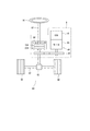
図1は、電動パワーステアリング装置8を備えるステアリングシステム90の全体構成を示すものである。ステアリングシステム90は、操舵部材であるステアリングホイール91、ステアリングシャフト92、ピニオンギア96、ラック軸97、車輪98、および、電動パワーステアリング装置8等を備える。
FIG. 1 shows the overall configuration of the
ステアリングホイール91は、ステアリングシャフト92と接続される。ステアリングシャフト92には、操舵トルクを検出するトルクセンサ94が設けられる。トルクセンサ94は、第1トルク検出部194および第2トルク検出部294を有しており、各々自身の故障検出ができるセンサが二重化されている。ステアリングシャフト92の先端には、ピニオンギア96が設けられる。ピニオンギア96は、ラック軸97に噛み合っている。ラック軸97の両端には、タイロッド等を介して一対の車輪98が連結される。
The
運転者がステアリングホイール91を回転させると、ステアリングホイール91に接続されたステアリングシャフト92が回転する。ステアリングシャフト92の回転運動は、ピニオンギア96によってラック軸97の直線運動に変換される。一対の車輪98は、ラック軸97の変位量に応じた角度に操舵される。
When the driver rotates the
電動パワーステアリング装置8は、モータ80、モータ80の回転を減速してステアリングシャフト92に伝える動力伝達部としての減速ギア89、および、ECU10等を備える。すなわち、本実施形態の電動パワーステアリング装置8は、所謂「コラムアシストタイプ」であるが、モータ80の回転をラック軸97に伝える所謂「ラックアシストタイプ」等としてもよい。本実施形態では、ステアリングシャフト92が「駆動対象」に対応する。
The electric power steering device 8 includes a
図2および図3に示すように、モータ80は、操舵に要するトルクの一部または全部を出力するものであって、電源としてのバッテリ191、291(図4参照)から電力が供給されることにより駆動され、減速ギア89を正逆回転させる。モータ80は、3相ブラシレスモータであって、ロータ860およびステータ840を有する。
As shown in FIGS. 2 and 3, the
モータ80は、第1モータ巻線180および第2モータ巻線280を有する。モータ巻線180、280は電気的特性が同等であり、共通のステータ840に、互いに電気角30[deg]ずらしてキャンセル巻きされる。これに応じて、モータ巻線180、280には、位相φが30[deg]ずれた相電流が通電されるように制御される。通電位相差を最適化することで、出力トルクが向上する。また、6次のトルクリプルを低減することができ、騒音、振動の低減することができる。また、電流も分散されることで発熱が分散、平準化されるため、各センサの検出値やトルク等、温度依存の系統間誤差を低減可能であるとともに、通電可能な電流量を増やすことができる。モータ巻線180、280の電気的特性は異なっていてもよい。
The
以下、第1モータ巻線180の通電制御に係る第1インバータ回路120および第1制御部151等の組み合わせを第1系統L1、第2モータ巻線280の通電制御に係る第2インバータ回路220および第2制御部251等の組み合わせを第2系統L2とする。また、第1系統L1に係る構成を主に100番台で付番し、第2系統L2に係る構成を主に200番台で付番する。また、後述の第1系統L1の第1制御部151に係る構成を500番台、第2系統L2の第2制御部251に係る構成を600番台で付番する。第1系統L1および第2系統L2において、同様または類似の構成には、下2桁が同じとなるように付番し、適宜説明を省略する。以下適宜、「第1」を添え字の「1」、「第2」を添え字の「2」として記載する。
Hereinafter, the combination of the
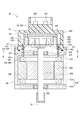
駆動装置40は、モータ80の軸方向の一方側にECU10が一体的に設けられており、いわゆる「機電一体型」であるが、モータ80とECU10とは別途に設けられていてもよい。ECU10は、モータ80の出力軸とは反対側において、シャフト870の軸Axに対して同軸に配置されている。ECU10は、モータ80の出力軸側に設けられていてもよい。機電一体型とすることで、搭載スペースに制約のある車両において、ECU10とモータ80とを効率的に配置することができる。
The
モータ80は、ステータ840、ロータ860、および、これらを収容するハウジング830等を備える。ステータ840は、ハウジング830に固定されており、モータ巻線180、280が巻回される。ロータ860は、ステータ840の径方向内側に設けられ、内部に磁石が埋め込まれており、ステータ840に対して相対回転可能に設けられる。すなわち本実施形態のモータ80は、埋め込み磁石型(IPM:Interior Permanent Magnet)モータである。
The
シャフト870は、ロータ860に嵌入され、ロータ860と一体に回転する。シャフト870は、軸受835、836により、ハウジング830に回転可能に支持される。シャフト870のECU10側の端部は、ハウジング830からECU10側に突出する。シャフト870のECU10側の端部には、マグネット875が設けられる。
The
ハウジング830は、リアフレームエンド837を含む有底筒状のケース834、および、ケース834の開口側に設けられるフロントフレームエンド838を有する。ケース834とフロントフレームエンド838とは、ボルト等により互いに締結されている。リアフレームエンド837には、リード線挿通孔839が形成される。リード線挿通孔839には、モータ巻線180、280の各相と接続されるリード線185、285が挿通される。リード線185、285は、リード線挿通孔839からECU10側に取り出され、基板470に接続される。
The
ECU10は、カバー460、カバー460に固定されているヒートシンク465、ヒートシンク465に固定されている基板470、および、基板470に実装される各種の電子部品等を備える。
The
カバー460は、外部の衝撃から電子部品を保護したり、ECU10の内部への埃や水等の浸入を防止したりする。カバー460は、カバー本体461、および、コネクタ部103、203が一体に形成される。コネクタ部103、203は、カバー本体461と別体であってもよい。コネクタ部103には、後述の電源コネクタ111、車両通信コネクタ112およびトルクコネクタが含まれ、コネクタ部203には、電源コネクタ211、車両通信コネクタ212およびトルクコネクタ213が含まれる(図4参照)。コネクタ部103、203の端子463は、図示しない配線等を経由して基板470と接続される。コネクタ数および端子数は、信号数等に応じて適宜変更可能である。コネクタ部103、203は、駆動装置40の軸方向の端部に設けられ、モータ80と反対側に開口する。
The
基板470は、例えばプリント基板であり、リアフレームエンド837と対向して設けられる。基板470には、2系統分の電子部品が系統ごとに独立して実装されており、完全冗長構成をなしている。本実施形態では、1枚の基板470に電子部品が実装されているが、複数枚の基板に電子部品を実装するようにしてもよい。
The
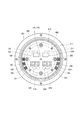
基板470の2つの主面のうち、モータ80側の面をモータ面471、モータ80と反対側の面をカバー面472とする。図3に示すように、モータ面471には、インバータ回路120を構成するスイッチング素子121、インバータ回路220を構成するスイッチング素子221、回転角検出部126、226、カスタムIC135、235等が実装される。回転角検出部126、226は、マグネット875の回転に伴う磁界の変化を検出可能なように、マグネット875と対向する箇所に実装される。
Of the two main surfaces of the
カバー面472には、コンデンサ128、228、インダクタ129、229、および、制御部151、251を構成するマイコン等が実装される。図3では、制御部151、251を構成するマイコンについて、それぞれ「151」、「251」を付番した。コンデンサ128、228は、バッテリ191、291から入力された電力を平滑化する。また、コンデンサ128、228は、電荷を蓄えることで、モータ80への電力供給を補助する。コンデンサ128、228、および、インダクタ129、229は、フィルタ回路を構成し、バッテリを共用する他の装置から伝わるノイズを低減するとともに、駆動装置40からバッテリを共用する他の装置に伝わるノイズを低減する。なお、図3中には図示を省略しているが、電源リレー、モータリレー、および、電流検出部127、227等についても、モータ面471またはカバー面472に実装される。
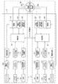
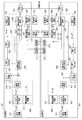
図4に示すように、ECU10は、インバータ回路120、220、および、制御部151、251等を備える。ECU10には、電源コネクタ111、211、車両通信コネクタ112、212、および、トルクコネクタ113、213が設けられる。第1電源コネクタ111は、第1バッテリ191に接続され、第2電源コネクタ211は、第2バッテリ291に接続される。電源コネクタ111、211は、同一のバッテリに接続されていてもよい。第1電源コネクタ111は、第1電源回路116を経由して、第1インバータ回路120と接続される。第2電源コネクタ211は、第2電源回路216を経由して、第2インバータ回路220と接続される。電源回路116、216は、例えば電源リレーである。
As shown in FIG. 4, the
車両通信コネクタ112は車両通信網195に接続され、車両通信コネクタ212は車両通信網295に接続される。車両通信コネクタ112、212は、それぞれ別途の車両通信網195、295に接続されているが、同一の車両通信網に接続されてもよい。また、図4では、車両通信網195、295として、CAN(Controller Area Network)を例示しているが、CAN−FD(CAN with Flexible Data rate)やFlexRay等、どのような規格のものでもよい。制御部151、251は、それぞれ、車両通信回路117、217を経由して車両通信網195、295と各種信号の送受信を行う。
The
トルクコネクタ113、213は、トルクセンサ94と接続される。詳細には、第1トルクコネクタ113は、トルクセンサ94の第1トルク検出部194と接続される。第2トルクコネクタ213は、トルクセンサ94に第2トルク検出部294と接続される。図4では、第1トルク検出部194を「トルクセンサ1」、第2トルク検出部294を「トルクセンサ2」と記載した。
The
第1制御部151は、トルクコネクタ113およびトルクセンサ入力回路118を経由して、トルクセンサ94の第1トルク検出部194から操舵トルクTsに係るトルク信号を取得可能である。第2制御部251は、トルクコネクタ213およびトルクセンサ入力回路218を経由して、トルクセンサ94の第2トルク検出部294から操舵トルクTsに係るトルク信号を取得可能である。これにより、制御部151、251は、トルク信号に基づき、操舵トルクTsを演算可能である。
The
第1インバータ回路120は、6つのスイッチング素子121を有する3相インバータであって、第1モータ巻線180へ供給される電力を変換する。スイッチング素子121は、第1制御部151から出力される制御信号に基づいてオンオフ作動が制御される。第2インバータ回路220は、6つのスイッチング素子221を有する3相インバータであって、第2モータ巻線280へ供給される電力を変換する。スイッチング素子221は、第2制御部251から出力される制御信号に基づいてオンオフ作動が制御される。
The
第1電流検出部127は、第1モータ巻線180の各相に通電される電流を検出し、検出値を第1制御部151に出力する。第2電流検出部227は、第2モータ巻線280の各相に通電される電流を検出し、検出値を第2制御部251に出力する。第1回転角検出部126は、モータ80の回転角を検出し、検出値を第1制御部151に出力する。第2回転角検出部226は、モータ80の回転角を検出し、検出値を第2制御部251に出力する。
The first
制御部151、251は、マイコン等を主体として構成され、内部にはいずれも図示しないCPU、ROM、RAM、I/O及び、これらの構成を接続するバスライン等を備えている。制御部151、251における各処理は、ROM等の実体的なメモリ装置(すなわち、読み出し可能非一時的有形記録媒体)に予め記憶されたプログラムをCPUで実行することによるソフトウェア処理であってもよいし、専用の電子回路によるハードウェア処理であってもよい。第1制御部151および第2制御部251は、相互に通信可能に設けられる。以下、制御部151、251間の通信を、「マイコン間通信」という。通信方法は、SPIやSENT等のシリアル通信や、CAN通信、FlexRay通信等、どのような方法を用いてもよい。後述の実施形態の各制御部についても同様である。
The
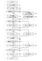
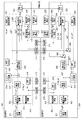
図5および図6に示すように、第1制御部151は、電気角演算部506、検出電流演算部507、トルク指令演算部511、基本指令演算部512、トルクd軸電流指令演算部519、弱め界磁演算部521、弱め界磁d軸電流指令調停部522、d軸電流指令演算部525、q軸電流指令演算部526、電流制御演算部530、PWM出力部555、送信部171、および、受信部172等を有する。
As shown in FIGS. 5 and 6, the
第2制御部251は、電気角演算部606、検出電流演算部607、トルク指令演算部611、基本指令演算部612、トルクd軸電流指令演算部619、弱め界磁演算部621、弱め界磁d軸電流指令調停部622、d軸電流指令演算部625、q軸電流指令演算部626、電流制御演算部630、PWM出力部655、送信部271、および、受信部272等を有する。
The
送信部171は、第1制御部151にて演算された値を第2制御部251に送信する。受信部172は、第2制御部251から送信された値を受信する。送信部271は、第2制御部251にて演算された値を第1制御部151に送信する。受信部272は、第1制御部151から送信された値を受信する。図6等では、記載の都合上、送信部171、271および受信部172、272を適宜分けて記載した。以下、自系統の値と他系統の値とを読み替えれば同様である点については、第2制御部251に係る説明は適宜省略し、第1制御部151を例に説明する。なお、図5については、第1制御部151について示しており、第2制御部251の記載は省略した。
The
電気角演算部506は、回転角検出部126の検出値に基づき、電気角θe1を演算する。検出電流演算部507は、電流検出部127の検出値に基づいて各相電流Iu1、Iv1、Iw2を演算する。また、検出電流演算部507は、電気角θe1を用いて各相電流Iu1、Iv1、Iw1をdq変換し、d軸電流検出値Id1およびq軸電流検出値Iq1を演算する。以下、d軸とq軸の値をまとめて記載する場合、「dq軸」とする。dq軸電流検出値Id1、Iq1は、自系統での電流制御演算に用いられる他、マイコン間通信にて第2制御部250に送信され、他系統での電流制御にも用いられる。
The electric
図5に示すように和差演算部508は、第1系統L1のdq軸電流検出値Id1、Iq1、および、第2系統L2のdq軸電流検出値Id2、Iq2を取得する。和差演算部508は、d軸電流検出値Id1、Id2の和であるd軸電流和Id+、d軸電流検出値Id1、Id2の差であるd軸電流差Id−、q軸電流検出値Iq1、Iq2の和であるq軸電流和Iq+、および、q軸電流検出値Iq1、Iq2の差であるq軸電流差Iq−を演算する。トルク電流演算部509は、d軸電流和Id+およびIq軸電流和Iq+に基づき、トルク電流検出値I_trq1を演算する。本実施形態では、トルク電流検出値I_trq1をモニタすることで、モータ80の出力トルクをモニタしている。
As shown in FIG. 5, the sum
図6に示すように、トルク指令演算部511は、操舵トルクや車速等に基づき、トルク指令値Trq1*を演算する。第1制御部151の基本指令演算部512は、トルク電流指令演算部513、電流制限演算部515、電流制限調停部516、および、電流制限部517を有し、基本電流指令値Ib1*を演算する。第2制御部251の基本指令演算部612は、トルク電流指令演算部613、切替部614、電流制限演算部615、電流制限調停部616、および、電流制限部617を有し、基本電流指令値Ib2*を演算する。
As shown in FIG. 6, the torque
トルク電流指令演算部513、613は、トルク指令値Trq1*、Trq2*に基づき、例えば所定の係数を乗じることで、トルク電流指令値Itrq1*、Itrq2*を演算する。第1トルク電流指令値Itrq1*は、第2制御部251に送信される。
Torque current command calculation unit 513,613 torque command value Trq1 *, based on Trq2 *, for example, by multiplying a predetermined coefficient, the torque current command value Itrq1 *, calculates the Itrq2 *. The first torque current command value Itrq1 * is transmitted to the
切替部614は、制御に用いるトルク電流指令値Itrq1*、Itrq2*を切替可能である。本実施形態では、第1制御部151をマスター制御部、第2制御部251をスレーブ制御部とし、第2制御部251は、第1トルク電流指令値Itrq1*が正常であれば、第1トルク電流指令値Itrq1*を優先的に用いる。また、故障等により第1トルク電流指令値Itrq1*が取得できない、或いは、トルク電流指令値Itrq1*、Itrq2*の差が異常判定閾値より大きい等、トルク電流指令値Itrq1*が信頼できない場合には、自系統のトルク電流指令値Itrq2*を用いる。ここでは、第1トルク電流指令値Itrq1*が正常であって、切替部614にて第1トルク電流指令値Itrq1*が選択されるものとする。
The
電流制限演算部515は、過熱保護等のための電流制限値Ilim1を演算する。電流制限値Ilim1は、第2制御部251に送信される。また、第1制御部151は、第2制御部251で演算された電流制限値Ilim2を取得する。
The current
電流制限調停部516は、自系統の電流制限値Ilim1、および、他系統の電流制限値Ilim2に基づき、調停後電流制限値Ilim_a1を演算する。本実施形態では、ミニマムセレクトにて、調停後電流制限値Ilim_a1を演算する。すなわち、自系統の電流制限値Ilim1が他系統の電流制限値Ilim2より小さい場合、自系統の電流制限値Ilim1を調停後電流制限値Ilim_a1とし、自系統の電流制限値Ilim1が他系統の電流制限値Ilim2以上の場合、他系統の電流制限値Ilim2を調停後電流制限値Ilim_a1とする。
The current
電流制限部517は、トルク電流指令値Itrq1*および調停後電流制限値Ilim_a1に基づき、基本電流指令値Ib1*を演算する。トルク電流指令値Itrq1*が調停後電流制限値Ilim_a1より小さい場合、トルク電流指令値Itrq1*を基本電流指令値Ib1*とし、トルク電流指令値Itrq1*が調停後電流制限値Ilim_a1以上の場合、調停後電流制限値Ilim_a1を基本電流指令値Ib1*とする。電流制限部617では、切替部614で選択されたトルク電流指令値および調停後電流制限値Ilim_a2に基づき、基本電流指令値Ib2*を演算する。
The current limiting
トルクd軸電流指令演算部519は、基本電流指令値Ib1*に基づき、マップ演算等によりトルクd軸電流指令値Id_t1*を演算する。
The torque d-axis current
弱め界磁演算部521は、電流制限値Ilim1、最大印加電圧に対する飽和値、および、電圧指令値の変調率等に基づき、制限前弱め界磁d軸電流指令値Id_wb1*を演算する。
The field
また、弱め界磁演算部521は、和差演算部508からq軸電流和Iq+を取得し、q軸電流和Iq+に基づいて弱め界磁d軸電流制限値Id_lim_w1を演算する。本実施形態では、図7に示すマップを用いたマップ演算により弱め界磁d軸電流制限値Id_lim_w1を演算する。図7では、系統を示す添え字を省略する。弱め界磁d軸電流制限値Id_lim_w1の演算に用いるマップは、基本電流指令値Ib1*に基づいて選択される。詳細には、基本電流指令値Ib1*がマップ切替判定値より大きい場合、制限値算出マップHiを用い、基本電流指令値Ib1*がマップ切替判定値以下の場合、制限値算出マップLoを用いる。マップ切替判定値は任意に設定可能である。また、図7の例では2つのマップを切り替えているが、切り替えるマップ数は1つでも3つ以上であってもよい。
Further, the field weakening
弱め界磁演算部521は、制限前弱め界磁d軸電流指令値Id_wb1*の絶対値が弱め界磁d軸電流制限値Id_lim_w1の絶対値より小さい場合、制限前弱め界磁d軸電流指令値Id_wb1*をそのまま弱め界磁d軸電流指令値Id_w1*とする。また、制限前弱め界磁d軸電流指令値Id_wb1*の絶対値が弱め界磁d軸電流制限値Id_lim_w1の絶対値以上の場合、弱め界磁d軸電流制限値Id_lim_w1を弱め界磁d軸電流指令値Id_w1*とする。弱め界磁d軸電流指令値Id_w1*は、第2制御部251に送信される。また、第1制御部151は、第2制御部251で演算された弱め界磁d軸電流指令値Id_w2*を取得する。すなわち電流制限において、d軸電流が負の値であれば、絶対値が小さい方の値が選択される。
When the absolute value of the field weakening field d-axis current command value Id_wb1 * before the limit is smaller than the absolute value of the field weakening field d-axis current limit value Id_lim_w1, the field weakening
弱め界磁d軸電流指令調停部522は、自系統の弱め界磁d軸電流指令値Id_w1*、および、他系統の弱め界磁d軸電流指令値Id_w2*に基づき、調停後弱め界磁d軸電流指令値Id_wa1*を演算する。本実施形態では、ミニマムセレクトにて、調停後弱め界磁d軸電流指令値Id_wa1*を演算する。すなわち、自系統の弱め界磁d軸電流指令値Id_wa1*が他系統の弱め界磁d軸電流指令値Id_wa2*より小さい場合、自系統の弱め界磁d軸電流指令値Id_wa1*を調停後弱め界磁d軸電流指令値Id_wa1*とし、自系統の弱め界磁d軸電流指令値Id_wa1*が他系統の弱め界磁d軸電流指令値Id_wa2*以上の場合、他系統の弱め界磁d軸電流指令値Id_wa2*を調停後弱め界磁d軸電流指令値Id_wa1*とする。なお、d軸電流が負の値であれば、ミニマムセレクトでは、絶対値が大きい方の値が選択されることを補足しておく。他のd軸電流に係るミニマムセレクトも同様である。なお、図5では、簡略化のため、弱め界磁d軸電流指令調停部522の記載を省略し、自系統の弱め界磁d軸電流指令値Id_w1*がd軸電流指令演算部525に入力されるものとして記載した。
Field weakening d-axis current
d軸電流指令演算部525は、トルクd軸電流指令値Id_t1*および調停後弱め界磁d軸電流指令値Id_wa1*に基づき、d軸電流指令値Id1*を演算する。本実施形態では、ミニマムセレクトにて、d軸電流指令値Id1*を演算する。すなわち、トルクd軸電流指令値Id_t1*が調停後弱め界磁d軸電流指令値Id_wa1*より小さい場合、トルクd軸電流指令値Id_t1*をd軸電流指令値Id1*とし、トルクd軸電流指令値Id_t1*が調停後弱め界磁d軸電流指令値Id_wa1*より大きい場合、調停後弱め界磁d軸電流指令値Id_wa1*をd軸電流指令値Id1*とする。q軸電流指令演算部526は、基本電流指令値Ib1*およびd軸電流指令値Id1*に基づき、例えばマップ演算によりq軸電流指令値Iq1*を演算する。
The d-axis current
電流制御演算部530は、減算器531〜534、電流フィードバック制御部541〜544、および、電圧指令演算部550等を有する。減算器531は、d軸電流指令値Id1*からd軸電流和Id+を減算し、d軸電流和偏差ΔId+を演算する。減算器532は、q軸電流指令値Iq1*からq軸電流和Iq+を減算し、q軸電流和偏差ΔIq+を演算する。減算器533は、d軸電流差指令値Id−*からd軸電流差Id−を減算し、d軸電流差偏差ΔId−を演算する。減算器534は、q軸電流差指令値Iq−*からq軸電流差Iq−を減算し、q軸電流差偏差ΔIq−を演算する。
The current
電流フィードバック制御部541〜544は、それぞれ、d軸電流和偏差ΔId+、q軸電流和偏差ΔIq+、d軸電流差偏差ΔId−、q軸電流差偏差ΔIq−が0に収束するように、例えばPI演算等により、d軸電圧和指令値Vd+*、q軸電圧和指令値Vq+*、d軸電圧差指令値Vd−*、q軸電圧差指令値Vq−*を演算する。電圧指令演算部550は、d軸電圧和指令値Vd+*、q軸電圧和指令値Vq+*、d軸電圧差指令値Vd−*、および、q軸電圧差指令値Vq−*に基づき、電圧指令値Vd1*、Vq1*、Vd2*、Vq2*を演算する。
The current
PWM出力部555は、電圧指令値Vd1*、Vq1*を逆dq変換した3相電圧指令Vu1*、Vv1*、Vw1*に基づき、PWM信号を生成する。PWM信号は、信号タイミングが系統間で揃うよう、例えば同期信号等により同期される。同期信号は、一方の系統から他方の信号に送信されるようにしてもよいし、両系統が外部から取得するようにしてもよい。
The
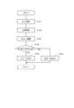
本実施形態の電流指令演算処理を図8のフローチャートに基づいて説明する。この処理は、制御部151、251にて所定の周期で実行されるものであって、主にd軸電流指令演算について示すものである。以下、ステップS11の「ステップ」を省略し、単に記号「S」と記す。他のステップも同様である。S11、S12およびS17以降の処理については、制御部151、251にて共通であるので、主に第1制御部151での制御として説明する。第2制御部251については、自系統の値と他系統の値とを読み替えればよい。他の実施形態の制御についても、制御部151、251で共通の制御については同様とする。フローチャートにおいては、系統を示す添え字の「1」、「2」を省略し、自系統の値を「自」、他系統の値を「他」とした。
The current command calculation process of this embodiment will be described with reference to the flowchart of FIG. This process is executed by the
S11では、トルク電流指令演算部513はトルク電流指令値Itrq1*を演算し、電流制限演算部515は電流制限値Ilim1を演算する。S22では、弱め界磁演算部521は、弱め界磁d軸電流指令値Id_w1*を演算する。弱め界磁d軸電流指令演算処理を図9のサブフローに基づいて説明する。
In S11, the torque current
S121では、弱め界磁演算部521は、制限前弱め界磁d軸電流指令値Id_wb1*を演算する。S122では、弱め界磁演算部521は、和差演算部508からq軸電流和Iq+を取得する。S123では、q軸電流和Iq+に基づくマップ演算(図7参照)により、弱め界磁d軸電流制限値Id_lim_w1を演算する。S121と、S122およびS123との処理順は入れ替えてもよい。
In S121, the field weakening
S124では、弱め界磁演算部521は、制限前弱め界磁d軸電流指令値Id_wb1*の絶対値が弱め界磁d軸電流制限値Id_lim_w1の絶対値より小さいか否かを判断する。制限前弱め界磁d軸Id_wb1*の絶対値が弱め界磁d軸電流制限値Id_lim_w1の絶対値より小さいと判断された場合(S124:YES)、S125へ移行し、制限前弱め界磁d軸電流指令値Id_wb1*を、弱め界磁d軸電流指令値Id_w1*とする。制限前弱め界磁d軸Id_wb1*の絶対値が弱め界磁d軸電流制限値Id_lim_w1の絶対値以上であると判断された場合(S124:NO)、S126へ移行し、弱め界磁d軸電流制限値Id_lim_w1を、弱め界磁d軸電流指令値Id_w1*とする。
In S124, the field weakening
図8へ戻り、S13では、制御部151、251は、自系統が電流指令値演算に係るマスター系統か否かを判断する。自系統が電流指令値演算に係るマスター系統であると判断された場合(S13:YES)、S14へ移行し、自系統が電流指令値演算に係るマスター系統ではないと判断された場合(S13:NO)、すなわち自系統が電流指令値演算に係るスレーブ系統である場合、S15へ移行する。本実施形態では、第1系統L1をマスター、第2系統L2をスレーブとするので、第1制御部151では肯定判断され、第2制御部251では否定判断されるので、S14については第1制御部151の処理として説明し、S15およびS16については第2制御部251の処理として説明する。図13中のS54〜S56、および、図15中のS88〜S90も同様とする。
Returning to FIG. 8, in S13, the
自系統がマスター系統である場合に移行するS14では、第1制御部151は、トルク電流指令値Itrq1*を送信し、電流制限値Ilim1、Ilim2および弱め界磁d軸電流指令値Id_w1*、Id_w2*を送受信する。自系統がスレーブ系統である場合に移行するS15では、第2制御部251は、マスター系統のトルク電流指令値Itrq1*を受信し、電流制限値Ilim1、Ilim2および弱め界磁d軸電流指令値Id_w1*、Id_w2*を送受信する。また、フローチャート中の記載は省略しているが、S14およびS15では、同時にdq軸の電流検出値Id1、Iq1、Id2、Iq2を送り合う。dq軸の電流検出値に替えて、3相の電流検出値を送り合い、受信した側でdq変換を行ってもよい。後述のS33、S54、S55、S73も同様である。
In S14, which shifts to the case where the own system is the master system, the
S16では、第2制御部251は、制御に用いるトルク電流指令を選択する。本実施形態では、マイコン間通信が正常、マスター系統である第1系統L1の駆動が正常、かつ、トルク電流指令値Itrq1*、Itrq2*の差がトルク指令異常判定閾値以下の場合、制御に用いるトルク電流指令値として、マスター系統のトルク電流指令値Itrq1*を選択する。また、マイコン間通信が異常、第1系統L1が正常動作していない、または、トルク電流指令値Itrq1*、Itrq2*の差が異常判定閾値より大きい場合、制御に用いるトルク電流指令値として、自系統のトルク電流指令値Itrq2*を選択する。
In S16, the
S17では、電流制限調停部516は、自系統の電流制限値Ilim1が他系統の電流制限値Ilim2より小さいか否かを判断する。自系統の電流制限値Ilim1が他系統の電流制限値Ilim2より小さいと判断された場合(S17:YES)、S18へ移行し、自系統の電流制限値Ilim1を、調停後電流制限値Ilim_a1とする。自系統の電流制限値Ilim1が他系統の電流制限値Ilim2以上であると判断された場合(S17:NO)、S19へ移行し、他系統の電流制限値Ilim2を、調停後電流制限値Ilim_a1とする。
In S17, the current
S20では、電流制限部517は、トルク電流指令値Itrq1*が調停後電流制限値Ilim_a1より小さいか否か判断する。トルク電流指令値Itrq1*が調停後電流制限値Ilim_a1より小さいと判断された場合(S20:YES)、S21へ移行し、トルク電流指令値Itrq1*を基本電流指令値Ib1*とする。トルク電流指令値Itrq1*が調停後電流制限値Ilim_a1以上であると判断された場合(S18:YES)、S20へ移行し、調停後電流制限値Ilim_a1を、基本電流指令値Ib1*とする。
In S20, the current limiting
S23では、トルクd軸電流指令演算部519は、トルクd軸電流指令値Id_t1*を演算する。トルクd軸電流指令値Id_t1*の演算は、基本電流指令値Ib1*の演算後、S27までのいずれのタイミングで行ってもよく、ステップ順は適宜入れ替え可能である。
In S23, the torque d-axis current
S24では、弱め界磁d軸電流指令調停部522は、自系統の弱め界磁d軸電流指令値Id_w1*が他系統の弱め界磁d軸電流指令値Id_w2*より小さいか否かを判断する。自系統の弱め界磁d軸電流指令値Id_w1*が他系統の弱め界磁d軸電流指令値Id_w2*より小さいと判断された場合(S24:YES)、S25へ移行し、自系統の弱め界磁d軸電流指令値Id_w1*を、調停後弱め界磁d軸電流指令値Id_wa1*とする。自系統の弱め界磁d軸電流指令値Id_w1*が他系統の弱め界磁d軸電流指令値Id_w2*以上であると判断された場合(S24:NO)、S26へ移行し、他系統の弱め界磁d軸電流指令値Id_w2*を、調停後弱め界磁d軸電流指令値Id_wa1*とする。
In S24, the field weakening field d-axis
S27では、d軸電流指令演算部625は、トルクd軸電流指令値Id_t1*が調停後弱め界磁d軸電流指令値Id_wa1*より小さいか否かを判断する。トルクd軸電流指令値Id_t1*が調停後弱め界磁d軸電流指令値Id_wa1*より小さいと判断された場合(S27:YES)、S28へ移行し、トルクd軸電流指令値Id_t1*を、d軸電流指令値Id1*とする。トルクd軸電流指令値Id_t1*が調停後弱め界磁d軸電流指令値Id_wa1*以上であると判断された場合(S27:NO)、S29へ移行し、調停後弱め界磁d軸電流指令値Id_wa1*を、d軸電流指令値Id1*とする。演算されたd軸電流指令値Id1*は、q軸電流指令演算、および、電流制御演算に用いられる。
In S27, the d-axis current
本実施形態では、マスター系統のトルク電流指令値Itrq1*を全系統で用いるとともに、電流制限値Ilim1、Ilim2および弱め界磁d軸電流指令値Id_w1*、Id_w2*を系統間で共有している。これにより、各系統の電流制御演算部530、630にて用いられる最終的なd軸電流指令値Id1*、Id2*およびq軸電流指令値Iq1*、Iq2*が揃うので、d軸電流でもトルクが発生するIPMモータにも好適に適用可能である。
In the present embodiment, the torque current command value Itrq1 * of the master system is used in all the systems, and the current limit values Illim1, Ilim2 and the field weakening field d-axis current command values Id_w1 * and Id_w2 * are shared between the systems. As a result, the final d-axis current command values Id1 * and Id2 * and the q-axis current command values Iq1 * and Iq2 * used in the current
また、各系統にて共有される値は、電流検出値を共有するタイミングにて同時に送受信可能であって、最終的なd軸電流指令値Id1*、Id2*およびq軸電流指令値Iq1*、Iq2*はそれぞれの系統で演算している。そのため、制御性を悪化させることなく、1回の電流制御における双方向通信回数を1回とすることができるので、複数回の通信を行う場合と比較して、演算負荷を低減することができる。 Further, the values shared by each system can be transmitted and received at the same time when the current detection value is shared, and the final d-axis current command values Id1 * , Id2 * and q-axis current command value Iq1 * , Iq2 * is calculated in each system. Therefore, since the number of bidirectional communications in one current control can be set to one without deteriorating the controllability, the calculation load can be reduced as compared with the case where a plurality of communications are performed. ..
以上説明したように、ECU10は、モータ巻線180、280を有するモータ80の駆動を制御するものであって、相互に通信可能な複数の制御部151、251を備える。制御部151、251は、基本指令演算部512、612、弱め界磁演算部521、621、および、信号生成部を有する。本実施形態では、電流制御演算部530、630およびPWM出力部555、655が「信号生成部」に対応し、基本電流指令値Ib1*、Ib2*と弱め界磁d軸電流指令値Id_w1*、Id_w2*とに基づいて演算されるd軸電流指令値Id1*、Id2*およびq軸電流指令値Iq1*、Iq2*に基づいて駆動信号としてのPWM信号を生成する。
As described above, the
本実施形態では、PWM信号の生成に用いられる指令値の少なくとも一部が、複数の制御部151、251にて共有される。これにより、指令値を共有しない独立制御と比較し、系統間誤差を低減することができ、d軸電流を考慮しつつ、モータ80の駆動を適切に制御することができる。
In the present embodiment, at least a part of the command values used for generating the PWM signal is shared by the plurality of
d軸電流指令演算部625、625は、基本電流指令値Ib1*、Ib2*に基づいて演算されるトルクd軸電流指令値Id_t1、Id_t2、および、弱め界磁電流指令値に基づき、d軸電流指令値Id1*、Id2*を演算する。本実施形態では、トルクd軸電流指令値Id_t1、Id_t2、または、d軸に係る値である弱め界磁電流指令値の小さい方の値を、d軸電流指令値Id1*、Id2*として選択する。 d-axis current command calculating unit 625,625, the basic current instruction value Ib1 *, Ib2 * torque d-axis current command value calculated based on Id_t1, Id_t2, and, based on the weak field current command value, the d-axis current The command values Id1 * and Id2 * are calculated. In the present embodiment, the torque d-axis current command values Id_t1, Id_t2, or the smaller value of the field weakening current command value, which is a value related to the d-axis, is selected as the d-axis current command values Id1 * and Id2 * . ..
本実施形態では、弱め界磁d軸電流指令値Id_w1*、Id_w2*が複数の制御部151、251にて共有され、弱め界磁d軸電流指令調停部522、622は、共有された弱め界磁d軸電流指令値Id_w1*、Id_w2*に基づいて調停後弱め界磁d軸電流指令値Id_wa1*、Id_wa2*を演算する。本実施形態では、調停後弱め界磁d軸電流指令値Id_wa1*、Id_wa2*として、弱め界磁d軸電流指令値Id_w1*、Id_w2*の小さい方の値を選択する。d軸電流指令演算部525、625は、調停後弱め界磁d軸電流指令値Id_wa1*、Id_wa2*を「弱め界磁電流指令値」として用いる。これにより、d軸電流を系統間で揃えることができる。また、駆動信号の生成に用いられる最終的なd軸電流指令値Id1*、Id2*は、各制御部151、251にて演算されたものを用いるため、最終的なd軸電流指令値Id1*、Id2*を共有する場合と比較し、制御性を低下させることなく、演算負荷を低減することができる。
In the present embodiment, the field weakening field d-axis current command values Id_w1 * and Id_w2 * are shared by the plurality of
第1制御部151は、トルク指令値trq1*に応じたトルク電流指令値Itrq1*をマスタートルク電流指令値として第2制御部251に送信し、第2制御部251は、マスタートルク電流指令値であるトルク電流指令値Itrq1*が正常である場合、トルク電流指令値Itrq1*に基づいて基本電流指令値Ib2*を演算し、トルク電流指令値Itrq1*が信頼できない場合、自身で演算したトルク電流指令値Itrq2*に基づいて基本電流指令値Ib2*を演算する。
The
ここで、「トルク電流指令値が信頼できない場合」とは、通信異常等によりトルク電流指令値が取得できない場合、マスター制御部に係る系統が異常停止している場合、および、自系統のトルク電流指令値との差が異常判定閾値より大きい場合の少なくとも1つを含む。その他の情報を用いて信頼できるか否か判定してもよい。第4実施形態におけるd軸電流指令値についても同様である。 Here, "when the torque current command value is unreliable" means that the torque current command value cannot be obtained due to a communication error or the like, the system related to the master control unit is abnormally stopped, and the torque current of the own system. Includes at least one case where the difference from the command value is larger than the abnormality determination threshold. Other information may be used to determine if it is reliable. The same applies to the d-axis current command value in the fourth embodiment.
これにより、正常時のトルク電流指令値を揃えることができるとともに、マスタートルク電流指令値が信頼できない場合であっても、モータ80の駆動制御を継続することができる。
As a result, the torque / current command values in the normal state can be made uniform, and the drive control of the
特に本実施形態では、トルク電流指令値Itrq1*が第1制御部151から第2制御部251に送信されることで共有され、弱め界磁d軸電流指令値Id_w1*、Id_w2*が相互に送受信されることで共有される。トルク電流指令値Itrq1*に加え、弱め界磁d軸電流指令値Id_w1*、Id_w2*を共有することで、d軸電流でもトルクが発生するIPMモータであっても各系統から出力されるトルクを揃えることができる。
In particular, in the present embodiment, the torque current command value Itrq1 * is shared by being transmitted from the
弱め界磁演算部521、621は、複数のモータ巻線180、280のq軸電流の和であるq軸電流和Iq+に基づいて弱め界磁d軸電流制限値Id_lim_w1、Id_lim_w2を演算し、制限前弱め界磁d軸電流指令値Id_wb1*、Id_wb2*の絶対値が弱め界磁d軸電流制限値Id_lim_w1、Id_lim_w2の絶対値以上である場合、弱め界磁電流指令値を弱め界磁d軸電流制限値Id_lim_w1、Id_lim_w2に制限する。また、弱め界磁演算部521、621は、基本電流指令値Ib1*、Ib2*に応じ、弱め界磁d軸電流制限値Id_lim_w1、Id_lim_w2の演算を切り替える。本実施形態では、基本電流指令値Ib1*、Ib2*に応じ、演算に用いるマップを切り替える。これにより、弱め界磁電流指令値を適切に演算することができる。
The field
(第2実施形態)
第2実施形態を図10および図11に示す。図10に示すように、本実施形態の制御部152、252は、基本指令演算部560、660が上記実施形態と異なる。基本指令演算部560は、トルク電流指令演算部513、電流制限演算部515、および、電流制限部517を有する。基本指令演算部660は、トルク電流指令演算部613、電流制限演算部615、および、電流制限部617を有する。
(Second Embodiment)
A second embodiment is shown in FIGS. 10 and 11. As shown in FIG. 10, in the
本実施形態では、第1制御部152から第2制御部252へのトルク電流指令値Itrq1*の送信を行っておらず、電流制限値Ilim1、Ilim2の送受信を行っていないため、切替部614および電流制限調停部516、616が省略されている。すなわち、本実施形態では、弱め界磁d軸電流指令値Id_w1*、Id_w2*を共有して調停しており、トルク電流指令値Itrq1*および電流制限値Ilim1、Ilim2は共有していない。
In the present embodiment, the torque current command value Itrq1 * is not transmitted from the
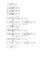
本実施形態の電流指令演算処理を図11のフローチャートに基づいて説明する。S31およびS32の処理は、図8中のS11およびS12の処理と同様である。S33では、制御部152、252は、弱め界磁d軸電流指令値Id_w1*、Id_w2*を送受信する。S34〜S43の処理は、図8中のS20〜S29の処理と同様である。
The current command calculation process of this embodiment will be described with reference to the flowchart of FIG. The processing of S31 and S32 is the same as the processing of S11 and S12 in FIG. In S33, the
本実施形態では、電流検出値と同時の1回の通信にて、弱め界磁d軸電流指令値Id_w1*、Id_w2*を系統間で共有することができ、例えばd軸電流指令演算部525、625にて、調停後弱め界磁d軸電流指令値Id_wa1*、Id_wa2*が選択されれば、d軸電流指令値Id1*、Id2*を揃えることができる。また、上記実施形態と同様の効果を奏する。
In the present embodiment, the field weakening field d-axis current command values Id_w1 * and Id_w2 * can be shared between the systems by one communication at the same time as the current detection value. For example, the d-axis current
(第3実施形態)
第3実施形態を図12および図13に示す。本実施形態の制御部153、253では、弱め界磁d軸電流指令値Id_w1*、Id_w2*が共有されておらず、弱め界磁d軸電流指令調停部522、622が省略されている点を除き、第1実施形態の制御部151、251と同様である。
(Third Embodiment)
A third embodiment is shown in FIGS. 12 and 13. The
本実施形態の電流指令演算処理を図13のフローチャートに基づいて説明する。S51〜S53の処理は、図8中のS11〜S13の処理と同様である。自系統がマスター系統である場合に移行するS54では、第1制御部151は、トルク電流指令値Itrq1*を送信し、電流制限値Ilim1、Ilim2を送受信する。自系統がスレーブ系統である場合に移行するS55では、トルク電流指令値Itrq1*を受信し、電流制限値Ilim1、Ilim2を送受信する。
The current command calculation process of this embodiment will be described with reference to the flowchart of FIG. The processing of S51 to S53 is the same as the processing of S11 to S13 in FIG. In S54, which shifts to the case where the own system is the master system, the
S56〜S63は、図8中のS16〜S23と同様である。S64では、d軸電流指令演算部525は、トルクd軸電流指令値Id_t1*が弱め界磁d軸電流指令値Id_w1*より小さいか否か判断する。トルクd軸電流指令値Id_t1*が弱め界磁d軸電流指令値Id_w1*より小さいと判断された場合(S64:YES)、S65へ移行し、トルクd軸電流指令値Id_t1*を、d軸電流指令値Id1*とする。トルクd軸電流指令値Id_t1*が弱め界磁d軸電流指令値Id_w1*以上であると判断された場合(S64:NO)、S66へ移行し、弱め界磁d軸電流指令値Id_w1*を、d軸電流指令値Id1*とする。
S56 to S63 are the same as S16 to S23 in FIG. In S64, the d-axis current
本実施形態では、電流検出値と同時の1回の通信にて、トルク電流指令値Itrq1*、Itrq2*を系統間で共有することができるので、モータ80がSPMモータであれば、q軸電流指令値Iq1*、Iq2*が揃えることができる。また、上記実施形態と同様の効果を奏する。
In the present embodiment, the torque current command values Itrq1 * and Itrq2 * can be shared between the systems by one communication at the same time as the current detection value. Therefore, if the
(第4実施形態)
第4実施形態を図14および図15に示す。本実施形態の第1制御部154は、トルク電流指令値Itrq1*に替えて、最終的なd軸電流指令値Id1*およびq軸電流指令値Iq1*を第2制御部254に送信している点が第3実施形態の第1制御部153と異なる。
(Fourth Embodiment)
A fourth embodiment is shown in FIGS. 14 and 15. The
第2制御部254の基本指令演算部661は、切替部614が省略されている点が上記実施形態の基本指令演算部612と異なる。本実施形態では、第1制御部154からトルク電流指令値Itrq1*が送信されないので、電流制限部617では、自系統のトルク電流指令値Itrq2*を用いる。
The basic
また、第2制御部254は、トルク電流指令値Itrq1*に替えて、最終的なd軸電流指令値Id1*およびq軸電流指令値Iq1*を取得しており、切替部665、666を備える。切替部665は、電流制御演算部630にて用いるq軸電流指令値Iq1*、Iq2*を切替可能である。また、切替部666は、電流制御演算部630にて用いるd軸電流指令値Id1*、Id2*を切替可能である。
Further, the
本実施形態では、第1制御部154をマスター、第2制御部254をスレーブとし、マスター系統のdq軸電流指令値Id1*、Iq1*が正常であれば、dq軸の電流指令値Id1*、Iq1*を優先的に用いる。また、故障等により、マスター系統のdq軸電流指令値Id1*、Iq1*が取得できない、或いは、マスター系統のdq軸の電流指令値Id1*、Iq1*とId2*、Iq2*との差が異常判定閾値より大きい等、dq軸電流指令値Id1*、Iq1*が信頼できない場合には、自系統のdq軸電流指令値Id2*、Iq2*を用いる。
In the present embodiment, the
本実施形態の電流指令演算処理を図15のフローチャートに基づいて説明する。S71およびS72の処理は、図8中のS11およびS12の処理と同様である。S73では、制御部154、254は、電流制限値Ilim1、Ilim2および弱め界磁d軸電流Id_w1*、Id_w2*を送受信する。S74〜S86の処理は、図8中のS17〜S29の処理と同様である。
The current command calculation process of this embodiment will be described with reference to the flowchart of FIG. The processing of S71 and S72 is the same as the processing of S11 and S12 in FIG. In S73, the
S87の処理は、図8中のS13の処理と同様であって、自系統がマスター系統であると判断された場合(S87:YES)、S88へ移行し、自系統がスレーブ系統であると判断された場合(S87:NO)、S89へ移行する。 The processing of S87 is the same as the processing of S13 in FIG. 8, and when it is determined that the own system is the master system (S87: YES), the process proceeds to S88 and the own system is determined to be the slave system. If so (S87: NO), the process proceeds to S89.
自系統がマスター系統である場合に移行するS88では、第1制御部154は、dq軸電流指令値Id1*、Iq1*を第2制御部254に送信する。自系統がスレーブ系統である場合に移行するS89では、第2制御部254は、dq軸電流指令値Id1*、Iq2*を第1制御部154から受信する。
In S88, which shifts to the case where the own system is the master system, the
S90では、第2制御部254は、電流制御に用いるdq軸電流指令を選択する。本実施形態では、マイコン間通信が正常、マスター系統である第1系統L1の駆動が正常、d軸電流指令値Id1*、Id2*の差がd軸異常判定閾値以下、かつ、q軸電流指令値Iq1*、Iq2*の差がq軸異常判定閾値以下の場合、電流制御演算部630での演算に用いる電流指令として、マスター系統のdq軸電流指令値Id1*、Iq1*を選択する。また、マイコン間通信が異常、第1系統L1が正常動作していない、d軸電流指令値Id1*、Id2*の差がd軸異常判定閾値より大きい、または、q軸電流指令値Iq1*、Iq2*の差がq軸異常判定閾値より大きい場合、電流制御演算部630での演算に用いる電流指令として、自系統のdq軸の電流指令値Id2*、Iq2*を選択する。
In S90, the
本実施形態では、第1制御部154は、マスターd軸電流指令値としてd軸電流指令値Id1*、マスターq軸電流指令値としてq軸電流指令値Iq1*を第2制御部254に送信する。第2制御部254は、dq軸電流指令値Id1*、Iq1*が正常である場合、dq軸電流指令値Id1*、Iq1*を用いて駆動信号を生成し、qd軸電流指令値Id1*、Iq1*が信頼できない場合、自身で演算したdq軸電流指令値Id2*、Iq2*を用いて駆動信号を生成する。
In the present embodiment, the
本実施形態では、最終的なdq軸の電流指令値Id1*、Iq1*をマスターからスレーブに送るので、正常時において、各系統から出力されるトルクを揃えることができる。また、マスター側のdq軸電流指令値Id1*、Iq1*が信頼できない場合であっても、スレーブ側にて自身で演算したdq軸電流指令値Id2*、Iq2*を用いることで、モータ80の駆動制御を継続することができる。また、上記実施形態と同様の効果を奏する。
In the present embodiment, since the final dq-axis current command values Id1 * and Iq1 * are sent from the master to the slave, the torque output from each system can be made uniform in the normal state. Even if the dq-axis current command values Id1 * and Iq1 * on the master side are unreliable, the
上記実施形態では、ECU10が「回転電機制御装置」、モータ80が「回転電機」、電流制御演算部530、630およびPWM出力部555、655が「信号生成部」、PWM信号が「駆動信号」に対応する。また、第1制御部151〜154および第2制御部251〜254が「制御部」、第1制御部151〜154が「マスター制御部」、第2制御部251〜254が「スレーブ制御部」に対応し、トルク電流指令値Itrq1*が「マスタートルク電流指令値」、d軸電流指令値Id1*が「マスターd軸電流指令値」、q軸電流指令値Iq1*が「マスターq軸電流指令値」に対応する。
In the above embodiment, the
(他の実施形態)
上記実施形態では、制御部は2つである。他の実施形態では、制御部は3つ以上であってもよい。例えば第1実施形態等のように、マスタースレーブ構成とする場合、1つの制御部をマスター制御部、残りの制御部をスレーブ制御部とする。上記実施形態では、弱め界磁d軸電流指令調停部では、ミニマムセレクトにて、弱め界磁d軸電流指令値を演算する。他の実施形態では、例えば平均値等の演算値を弱め界磁d軸電流指令値とする、といった具合に、調停演算はミニマムセレクトに限らない。ミニマムセレクトとした他の演算処理についても同様である。
(Other embodiments)
In the above embodiment, there are two control units. In other embodiments, the number of control units may be three or more. For example, in the case of a master-slave configuration as in the first embodiment, one control unit is a master control unit and the remaining control units are slave control units. In the above embodiment, the field weakening d-axis current command arbitrator calculates the field weakening d-axis current command value by the minimum select. In another embodiment, the arbitration calculation is not limited to the minimum select, for example, the calculated value such as the average value is weakened to be the field d-axis current command value. The same applies to other arithmetic processing with minimum select.
上記実施形態では、モータ巻線およびインバータ部が2つずつ設けられる。他の実施形態では、モータ巻線およびインバータ部は、1つまたは3つ以上であってもよい。また、例えば複数のモータ巻線およびインバータ部に対して1つの制御部を設ける、或いは、1つの制御部に対して複数のインバータ部およびモータ巻線を設ける、といった具合に、モータ巻線、インバータ部および制御部の数が異なっていてもよい。 In the above embodiment, two motor windings and two inverters are provided. In other embodiments, there may be one or more motor windings and inverters. Further, for example, one control unit is provided for a plurality of motor windings and an inverter unit, or a plurality of inverter units and a motor winding are provided for one control unit, and so on. The number of units and the number of control units may be different.
上記実施形態では、回転電機は、3相ブラシレスのIPMモータである。他の実施形態では、回転電機は、IPMモータに限らず、SPMモータであってもよい。また、回転電機は、ブラシレスモータに限らず、発電機の機能を併せ持つ、所謂モータジェネレータであってもよい。また、上記実施形態では、回転電機制御装置は、電動パワーステアリング装置に適用される。他の実施形態では、回転電機制御装置を、ステアバイワイヤ装置等、操舵を司る電動パワーステアリング装置以外の装置に適用してもよい。 In the above embodiment, the rotary electric machine is a three-phase brushless IPM motor. In another embodiment, the rotary electric machine is not limited to the IPM motor, but may be an SPM motor. Further, the rotary electric machine is not limited to the brushless motor, and may be a so-called motor generator having a function of a generator. Further, in the above embodiment, the rotary electric machine control device is applied to the electric power steering device. In another embodiment, the rotary electric machine control device may be applied to a device other than the electric power steering device that controls steering, such as a steer-by-wire device.
本開示に記載の制御部及びその手法は、コンピュータプログラムにより具体化された一つ乃至は複数の機能を実行するようにプログラムされたプロセッサ及びメモリを構成することによって提供された専用コンピュータにより、実現されてもよい。あるいは、本開示に記載の制御部及びその手法は、一つ以上の専用ハードウェア論理回路によってプロセッサを構成することによって提供された専用コンピュータにより、実現されてもよい。もしくは、本開示に記載の制御部及びその手法は、一つ乃至は複数の機能を実行するようにプログラムされたプロセッサ及びメモリと一つ以上のハードウェア論理回路によって構成されたプロセッサとの組み合わせにより構成された一つ以上の専用コンピュータにより、実現されてもよい。また、コンピュータプログラムは、コンピュータにより実行されるインストラクションとして、コンピュータ読み取り可能な非遷移有形記録媒体に記憶されていてもよい。以上、本発明は、上記実施形態になんら限定されるものではなく、発明の趣旨を逸脱しない範囲において種々の形態で実施可能である。 The controls and methods thereof described in the present disclosure are realized by a dedicated computer provided by configuring a processor and memory programmed to perform one or more functions embodied by a computer program. May be done. Alternatively, the controls and methods thereof described in the present disclosure may be implemented by a dedicated computer provided by configuring the processor with one or more dedicated hardware logic circuits. Alternatively, the control unit and method thereof described in the present disclosure may be a combination of a processor and memory programmed to perform one or more functions and a processor composed of one or more hardware logic circuits. It may be realized by one or more dedicated computers configured. Further, the computer program may be stored in a computer-readable non-transitional tangible recording medium as an instruction executed by the computer. As described above, the present invention is not limited to the above-described embodiment, and can be implemented in various embodiments without departing from the spirit of the invention.
10・・・ECU(回転電機制御装置)
80・・・モータ(回転電機)
151〜154・・・第1制御部(制御部、マスター制御部)
251〜254・・・第2制御部(制御部、スレーブ制御部)
512、560、612、660、661・・・基本指令演算部
521、621・・・弱め界磁演算部
522、622・・・d軸電流指令調停部
525、625・・・d軸電流指令演算部
530、630・・・電流制御演算部(信号生成部)
555、655・・・PWM出力部(信号生成部)
10 ... ECU (rotary electric machine control device)
80 ... Motor (rotary machine)
151-154 ... 1st control unit (control unit, master control unit)
251 to 254 ... Second control unit (control unit, slave control unit)
512, 560, 612, 660, 661 ... Basic
555, 655 ... PWM output unit (signal generation unit)
Claims (7)
トルク指令値に基づいて基本電流指令値を演算する基本指令演算部(512、560、612、660、661)、弱め界磁電流指令値を演算する弱め界磁演算部(521、621)、ならびに、前記基本電流指令値と前記弱め界磁電流指令値とに基づいて演算されるd軸電流指令値およびq軸電流指令値に基づいて駆動信号を生成する信号生成部(530、555、630、655)を有し、相互に通信可能である複数の制御部(151〜154、251〜254)を備え、
前記駆動信号の生成に用いられる指令値の少なくとも一部が、複数の前記制御部にて共有される回転電機制御装置。 A rotary electric machine control device that controls the drive of a rotary electric machine (80) having a motor winding (180, 280).
The basic command calculation unit (512, 560, 612, 660, 661) that calculates the basic current command value based on the torque command value, the weak field calculation unit (521, 621) that calculates the weak field current command value, and , A signal generator (530, 555, 630) that generates a drive signal based on the d-axis current command value and the q-axis current command value calculated based on the basic current command value and the field weakening current command value. 655), including a plurality of control units (151 to 154, 251 to 254) capable of communicating with each other.
A rotary electric machine control device in which at least a part of command values used for generating the drive signal is shared by a plurality of the control units.
前記d軸電流指令演算部は、前記トルクd軸電流指令値、または、前記弱め界磁電流指令値の小さい方を、前記d軸電流指令値として選択する請求項1に記載の回転電機制御装置。 The control unit is a d-axis current command calculation unit that calculates the d-axis current command value based on the torque d-axis current command value calculated based on the basic current command value and the field weakening current command value. Has (525, 625) and
The rotary electric machine control device according to claim 1, wherein the d-axis current command calculation unit selects the smaller of the torque d-axis current command value or the weakening field current command value as the d-axis current command value. ..
前記制御部は、共有された前記弱め界磁電流指令値に基づいて調停後弱め界磁d軸電流指令値を演算する弱め界磁d軸電流指令調停部(522、622)を有し、
前記d軸電流指令演算部は、前記調停後弱め界磁電流指令値を、前記弱め界磁電流指令値として用いる請求項2に記載の回転電機制御装置。 The field weakening current command value calculated by each of the control units is shared as the command value by the plurality of control units.
The control unit has a field weakening d-axis current command arbitration unit (522, 622) that calculates a field weakening d-axis current command value after arbitration based on the shared field weakening current command value.
The rotary electric machine control device according to claim 2, wherein the d-axis current command calculation unit uses the field weakening current command value after arbitration as the field weakening current command value.
前記マスター制御部は、前記トルク指令値に応じたトルク電流指令値であるマスタートルク電流指令値を、前記指令値として前記スレーブ制御部に送信し、
前記スレーブ制御部は、
前記マスタートルク電流指令値が正常であると判断した場合、前記マスタートルク電流指令値に基づいて前記基本電流指令値を演算し、
前記マスタートルク電流指令値が信頼できないと判断した場合、自身で演算した前記トルク電流指令値に基づいて前記基本電流指令値を演算する請求項1〜3のいずれか一項に記載の回転電機制御装置。 Assuming that one of the control units is a master control unit and the control units other than the master control unit are slave control units,
The master control unit transmits a master torque current command value, which is a torque current command value corresponding to the torque command value, to the slave control unit as the command value.
The slave control unit
When it is determined that the master torque current command value is normal, the basic current command value is calculated based on the master torque current command value.
The rotary electric machine control according to any one of claims 1 to 3, wherein when it is determined that the master torque current command value is unreliable, the basic current command value is calculated based on the torque current command value calculated by itself. apparatus.
前記マスター制御部は、当該マスター制御部にて演算された前記d軸電流指令値および前記q軸電流指令値を前記指令値として、前記スレーブ制御部に送信し、
前記スレーブ制御部は、
前記マスター制御部から送信された前記d軸電流指令値であるマスターd軸電流指令値、および、前記マスター制御部から送信された前記q軸電流指令値であるマスターq軸電流指令値が正常であると判断した場合、前記マスターd軸電流指令値および前記q軸電流指令値を用いて前記駆動信号を生成し、
前記マスターd軸電流指令値および前記マスターq軸電流指令値が信頼できないと判断した場合、自身で演算した前記d軸電流指令値および前記q軸電流指令値を用いて前記駆動信号を生成する請求項1または2に記載の回転電機制御装置。 Assuming that one of the control units is a master control unit and the control units other than the master control unit are slave control units,
The master control unit transmits the d-axis current command value and the q-axis current command value calculated by the master control unit as the command values to the slave control unit.
The slave control unit
The master d-axis current command value, which is the d-axis current command value transmitted from the master control unit, and the master q-axis current command value, which is the q-axis current command value transmitted from the master control unit, are normal. When it is determined that there is, the drive signal is generated using the master d-axis current command value and the q-axis current command value.
When it is determined that the master d-axis current command value and the master q-axis current command value are unreliable, a request to generate the drive signal using the d-axis current command value and the q-axis current command value calculated by itself. Item 2. The rotary electric current control device according to Item 1 or 2.
前記弱め界磁演算部は、複数の前記モータ巻線のq軸電流の和であるq軸電流和に基づいて弱め界磁d軸電流制限値を演算し、制限前弱め界磁d軸電流指令値の絶対値が前記弱め界磁d軸電流制限値の絶対値以上である場合、前記弱め界磁電流指令値を前記弱め界磁d軸電流制限値に制限する請求項1〜5のいずれか一項に記載の回転電機制御装置。 There are a plurality of the motor windings,
The field weakening calculation unit calculates a field weakening d-axis current limit value based on the sum of q-axis currents, which is the sum of the q-axis currents of the plurality of motor windings, and commands a field weakening d-axis current before limiting. When the absolute value of the value is equal to or greater than the absolute value of the field weakening d-axis current limit value, any one of claims 1 to 5 for limiting the field weakening current command value to the field weakening d-axis current limit value. The rotary electric motor control device according to item 1.
Priority Applications (3)
| Application Number | Priority Date | Filing Date | Title |
|---|---|---|---|
| JP2019088832A JP7192649B2 (en) | 2019-05-09 | 2019-05-09 | Rotating electric machine controller |
| CN202010356481.5A CN111917354B (en) | 2019-05-09 | 2020-04-29 | Rotary electric machine control device |
| US16/867,429 US11285992B2 (en) | 2019-05-09 | 2020-05-05 | Rotating electric machine control device |
Applications Claiming Priority (1)
| Application Number | Priority Date | Filing Date | Title |
|---|---|---|---|
| JP2019088832A JP7192649B2 (en) | 2019-05-09 | 2019-05-09 | Rotating electric machine controller |
Publications (2)
| Publication Number | Publication Date |
|---|---|
| JP2020184855A true JP2020184855A (en) | 2020-11-12 |
| JP7192649B2 JP7192649B2 (en) | 2022-12-20 |
Family
ID=73044723
Family Applications (1)
| Application Number | Title | Priority Date | Filing Date |
|---|---|---|---|
| JP2019088832A Active JP7192649B2 (en) | 2019-05-09 | 2019-05-09 | Rotating electric machine controller |
Country Status (3)
| Country | Link |
|---|---|
| US (1) | US11285992B2 (en) |
| JP (1) | JP7192649B2 (en) |
| CN (1) | CN111917354B (en) |
Cited By (4)
| Publication number | Priority date | Publication date | Assignee | Title |
|---|---|---|---|---|
| WO2022186322A1 (en) * | 2021-03-05 | 2022-09-09 | 株式会社デンソー | Motor control device, and electric power steering device equipped with same |
| JPWO2023073823A1 (en) * | 2021-10-27 | 2023-05-04 | ||
| WO2024166613A1 (en) * | 2023-02-07 | 2024-08-15 | 株式会社デンソー | Rotating electric machine and control program |
| WO2024253064A1 (en) * | 2023-06-05 | 2024-12-12 | 株式会社デンソー | Rotating electric machine control device |
Families Citing this family (4)
| Publication number | Priority date | Publication date | Assignee | Title |
|---|---|---|---|---|
| KR102637909B1 (en) * | 2019-01-23 | 2024-02-19 | 에이치엘만도 주식회사 | Redundancy circuit for electric power steering system |
| US11211851B2 (en) * | 2019-05-10 | 2021-12-28 | Rockwell Automation Technologies, Inc. | System and method for providing safe limited force producing power in a motor |
| JP2021079893A (en) * | 2019-11-22 | 2021-05-27 | 株式会社ジェイテクト | Steering control device |
| WO2024004442A1 (en) * | 2022-06-27 | 2024-01-04 | 株式会社デンソー | Drive device and drive control device |
Citations (5)
| Publication number | Priority date | Publication date | Assignee | Title |
|---|---|---|---|---|
| JP2013074648A (en) * | 2011-09-27 | 2013-04-22 | Honda Motor Co Ltd | Electrically-driven power steering device |
| JP2013090551A (en) * | 2011-10-21 | 2013-05-13 | Aisin Aw Co Ltd | Rotary electric machine control device |
| JP2017017909A (en) * | 2015-07-03 | 2017-01-19 | 日立オートモティブシステムズ株式会社 | Motor control device and electric power steering device equipped with the same |
| JP2018050438A (en) * | 2016-09-23 | 2018-03-29 | 株式会社ジェイテクト | Motor control device and steering device |
| JP2018130007A (en) * | 2016-11-11 | 2018-08-16 | 株式会社デンソー | Rotary electric machine control apparatus and electric power steering apparatus using the same |
Family Cites Families (10)
| Publication number | Priority date | Publication date | Assignee | Title |
|---|---|---|---|---|
| JP3566163B2 (en) * | 2000-01-07 | 2004-09-15 | 株式会社東芝 | Motor control device |
| JP4655871B2 (en) * | 2005-10-19 | 2011-03-23 | 株式会社日立製作所 | Field weakening vector control device and module for permanent magnet synchronous motor |
| JP4797565B2 (en) * | 2005-10-21 | 2011-10-19 | 日本精工株式会社 | Motor drive control device |
| JP4754378B2 (en) * | 2006-03-22 | 2011-08-24 | 本田技研工業株式会社 | Electric motor control device |
| JP5109554B2 (en) | 2007-09-26 | 2012-12-26 | 株式会社ジェイテクト | Motor control device and electric power steering device |
| JP2011195089A (en) * | 2010-03-23 | 2011-10-06 | Jtekt Corp | Electric power steering device |
| US9054623B2 (en) * | 2011-08-10 | 2015-06-09 | Panasonic Intellectual Property Management Co., Ltd. | Motor control device |
| JP6488192B2 (en) * | 2015-05-25 | 2019-03-20 | 日立オートモティブシステムズ株式会社 | Inverter control device |
| WO2018088463A1 (en) | 2016-11-11 | 2018-05-17 | 株式会社デンソー | Rotary electric machine control device and electric power steering device using same |
| JP7077982B2 (en) | 2019-02-06 | 2022-05-31 | 株式会社デンソー | Motor control device and electric power steering device equipped with it |
-
2019
- 2019-05-09 JP JP2019088832A patent/JP7192649B2/en active Active
-
2020
- 2020-04-29 CN CN202010356481.5A patent/CN111917354B/en active Active
- 2020-05-05 US US16/867,429 patent/US11285992B2/en active Active
Patent Citations (5)
| Publication number | Priority date | Publication date | Assignee | Title |
|---|---|---|---|---|
| JP2013074648A (en) * | 2011-09-27 | 2013-04-22 | Honda Motor Co Ltd | Electrically-driven power steering device |
| JP2013090551A (en) * | 2011-10-21 | 2013-05-13 | Aisin Aw Co Ltd | Rotary electric machine control device |
| JP2017017909A (en) * | 2015-07-03 | 2017-01-19 | 日立オートモティブシステムズ株式会社 | Motor control device and electric power steering device equipped with the same |
| JP2018050438A (en) * | 2016-09-23 | 2018-03-29 | 株式会社ジェイテクト | Motor control device and steering device |
| JP2018130007A (en) * | 2016-11-11 | 2018-08-16 | 株式会社デンソー | Rotary electric machine control apparatus and electric power steering apparatus using the same |
Cited By (8)
| Publication number | Priority date | Publication date | Assignee | Title |
|---|---|---|---|---|
| WO2022186322A1 (en) * | 2021-03-05 | 2022-09-09 | 株式会社デンソー | Motor control device, and electric power steering device equipped with same |
| JP2022135662A (en) * | 2021-03-05 | 2022-09-15 | 株式会社デンソー | Motor control device, and electric power steering device provided with the same |
| JP7567565B2 (en) | 2021-03-05 | 2024-10-16 | 株式会社デンソー | MOTOR CONTROL DEVICE AND ELECTRIC POWER STEERING DEVICE INCLUDING THE SAME |
| JPWO2023073823A1 (en) * | 2021-10-27 | 2023-05-04 | ||
| WO2023073823A1 (en) * | 2021-10-27 | 2023-05-04 | 三菱電機株式会社 | Control device of rotating machine, and electric power steering device |
| JP7634807B2 (en) | 2021-10-27 | 2025-02-25 | 三菱電機モビリティ株式会社 | Rotating machine control device and electric power steering device |
| WO2024166613A1 (en) * | 2023-02-07 | 2024-08-15 | 株式会社デンソー | Rotating electric machine and control program |
| WO2024253064A1 (en) * | 2023-06-05 | 2024-12-12 | 株式会社デンソー | Rotating electric machine control device |
Also Published As
| Publication number | Publication date |
|---|---|
| JP7192649B2 (en) | 2022-12-20 |
| CN111917354A (en) | 2020-11-10 |
| CN111917354B (en) | 2024-08-23 |
| US20200353973A1 (en) | 2020-11-12 |
| US11285992B2 (en) | 2022-03-29 |
Similar Documents
| Publication | Publication Date | Title |
|---|---|---|
| US10862417B2 (en) | Rotary electric device control device and electric power steering device | |
| JP7192649B2 (en) | Rotating electric machine controller | |
| US11254352B2 (en) | Rotary electric machine control device, and electric power steering device using the same | |
| US11565744B2 (en) | Rotary electric machine control device and electric power steering device using same | |
| US11214304B2 (en) | Steering control apparatus | |
| US11400971B2 (en) | Rotary electric machine control device and method | |
| WO2018147402A1 (en) | Rotary electric machine control device and electric power steering device using same | |
| JP7238525B2 (en) | motor controller | |
| JP7136005B2 (en) | Control device for polyphase rotating machine | |
| WO2021029407A1 (en) | Dynamo-electric machine control device | |
| US20190256130A1 (en) | Rotary electric device control device, and electric power steering device using the same | |
| CN110890856B (en) | Control devices for three-phase rotating machinery | |
| JP7156211B2 (en) | Rotating electric machine controller | |
| JP6988373B2 (en) | Rotating electric machine control device and electric power steering device using this | |
| JP2021184677A (en) | Motor control device | |
| JP7183730B2 (en) | steering controller | |
| US20260088745A1 (en) | Rotary electric machine control device |
Legal Events
| Date | Code | Title | Description |
|---|---|---|---|
| A621 | Written request for application examination |
Free format text: JAPANESE INTERMEDIATE CODE: A621 Effective date: 20210825 |
|
| A131 | Notification of reasons for refusal |
Free format text: JAPANESE INTERMEDIATE CODE: A131 Effective date: 20220719 |
|
| A977 | Report on retrieval |
Free format text: JAPANESE INTERMEDIATE CODE: A971007 Effective date: 20220727 |
|
| A521 | Request for written amendment filed |
Free format text: JAPANESE INTERMEDIATE CODE: A523 Effective date: 20220908 |
|
| TRDD | Decision of grant or rejection written | ||
| A01 | Written decision to grant a patent or to grant a registration (utility model) |
Free format text: JAPANESE INTERMEDIATE CODE: A01 Effective date: 20221108 |
|
| A61 | First payment of annual fees (during grant procedure) |
Free format text: JAPANESE INTERMEDIATE CODE: A61 Effective date: 20221121 |
|
| R151 | Written notification of patent or utility model registration |
Ref document number: 7192649 Country of ref document: JP Free format text: JAPANESE INTERMEDIATE CODE: R151 |
|
| R250 | Receipt of annual fees |
Free format text: JAPANESE INTERMEDIATE CODE: R250 |