EP4039929A1 - Rolling device for sliding leaf of a door or window - Google Patents
Rolling device for sliding leaf of a door or window Download PDFInfo
- Publication number
- EP4039929A1 EP4039929A1 EP22155786.1A EP22155786A EP4039929A1 EP 4039929 A1 EP4039929 A1 EP 4039929A1 EP 22155786 A EP22155786 A EP 22155786A EP 4039929 A1 EP4039929 A1 EP 4039929A1
- Authority
- EP
- European Patent Office
- Prior art keywords
- housing
- cages
- cage
- end side
- roller
- Prior art date
- Legal status (The legal status is an assumption and is not a legal conclusion. Google has not performed a legal analysis and makes no representation as to the accuracy of the status listed.)
- Pending
Links
- 238000005096 rolling process Methods 0.000 title claims abstract description 35
- 230000000295 complement effect Effects 0.000 claims abstract description 11
- 238000003032 molecular docking Methods 0.000 description 3
- 238000010586 diagram Methods 0.000 description 2
- 230000005540 biological transmission Effects 0.000 description 1
- 230000003993 interaction Effects 0.000 description 1
- 230000007257 malfunction Effects 0.000 description 1
- 238000004519 manufacturing process Methods 0.000 description 1
Images

Classifications
-
- E—FIXED CONSTRUCTIONS
- E05—LOCKS; KEYS; WINDOW OR DOOR FITTINGS; SAFES
- E05D—HINGES OR SUSPENSION DEVICES FOR DOORS, WINDOWS OR WINGS
- E05D15/00—Suspension arrangements for wings
- E05D15/06—Suspension arrangements for wings for wings sliding horizontally more or less in their own plane
- E05D15/0621—Details, e.g. suspension or supporting guides
- E05D15/066—Details, e.g. suspension or supporting guides for wings supported at the bottom
- E05D15/0665—Details, e.g. suspension or supporting guides for wings supported at the bottom on wheels with fixed axis
- E05D15/0669—Details, e.g. suspension or supporting guides for wings supported at the bottom on wheels with fixed axis with height adjustment
-
- E—FIXED CONSTRUCTIONS
- E05—LOCKS; KEYS; WINDOW OR DOOR FITTINGS; SAFES
- E05Y—INDEXING SCHEME RELATING TO HINGES OR OTHER SUSPENSION DEVICES FOR DOORS, WINDOWS OR WINGS AND DEVICES FOR MOVING WINGS INTO OPEN OR CLOSED POSITION, CHECKS FOR WINGS AND WING FITTINGS NOT OTHERWISE PROVIDED FOR, CONCERNED WITH THE FUNCTIONING OF THE WING
- E05Y2201/00—Constructional elements; Accessories therefore
- E05Y2201/60—Suspension or transmission members; Accessories therefore
- E05Y2201/622—Suspension or transmission members elements
- E05Y2201/638—Cams; Ramps
-
- E—FIXED CONSTRUCTIONS
- E05—LOCKS; KEYS; WINDOW OR DOOR FITTINGS; SAFES
- E05Y—INDEXING SCHEME RELATING TO HINGES OR OTHER SUSPENSION DEVICES FOR DOORS, WINDOWS OR WINGS AND DEVICES FOR MOVING WINGS INTO OPEN OR CLOSED POSITION, CHECKS FOR WINGS AND WING FITTINGS NOT OTHERWISE PROVIDED FOR, CONCERNED WITH THE FUNCTIONING OF THE WING
- E05Y2201/00—Constructional elements; Accessories therefore
- E05Y2201/60—Suspension or transmission members; Accessories therefore
- E05Y2201/622—Suspension or transmission members elements
- E05Y2201/64—Carriers
-
- E—FIXED CONSTRUCTIONS
- E05—LOCKS; KEYS; WINDOW OR DOOR FITTINGS; SAFES
- E05Y—INDEXING SCHEME RELATING TO HINGES OR OTHER SUSPENSION DEVICES FOR DOORS, WINDOWS OR WINGS AND DEVICES FOR MOVING WINGS INTO OPEN OR CLOSED POSITION, CHECKS FOR WINGS AND WING FITTINGS NOT OTHERWISE PROVIDED FOR, CONCERNED WITH THE FUNCTIONING OF THE WING
- E05Y2900/00—Application of doors, windows, wings or fittings thereof
- E05Y2900/10—Application of doors, windows, wings or fittings thereof for buildings or parts thereof
- E05Y2900/13—Application of doors, windows, wings or fittings thereof for buildings or parts thereof characterised by the type of wing
- E05Y2900/132—Doors
-
- E—FIXED CONSTRUCTIONS
- E05—LOCKS; KEYS; WINDOW OR DOOR FITTINGS; SAFES
- E05Y—INDEXING SCHEME RELATING TO HINGES OR OTHER SUSPENSION DEVICES FOR DOORS, WINDOWS OR WINGS AND DEVICES FOR MOVING WINGS INTO OPEN OR CLOSED POSITION, CHECKS FOR WINGS AND WING FITTINGS NOT OTHERWISE PROVIDED FOR, CONCERNED WITH THE FUNCTIONING OF THE WING
- E05Y2900/00—Application of doors, windows, wings or fittings thereof
- E05Y2900/10—Application of doors, windows, wings or fittings thereof for buildings or parts thereof
- E05Y2900/13—Application of doors, windows, wings or fittings thereof for buildings or parts thereof characterised by the type of wing
- E05Y2900/148—Windows
Definitions
- the present invention relates to a rolling device for a sliding sash of a door or window comprising a casing accommodating at least two cages, one arranged behind the other, in a cage being mounted in rotation about a horizontal axis, a rolling roller .
- the present invention relates to the field of building hardware and relates, more particularly, to rolling devices intended to be associated with a sliding leaf of the door or window type.
- joinery of the door or window type, comprising at least one leaf mounted movable in translation on a fixed frame uses such rolling devices. It is through the latter that such a sliding leaf generally rests on the lower crosspiece of the fixed frame to make its movement easier.
- These rolling devices are usually mounted under the bottom rail of the sash. They are at least two in number located at the ends of the lower crosspiece, in all cases at least one located on each side of the transverse median plane of this sliding leaf.
- At least one of these rolling devices is provided with adjustment means acting essentially vertically on the running roller(s) with which they are provided.
- Such adjustment means can take different embodiments, including that of an adjustment screw directly on the rolling device or of a more complex assembly, using transmission rods making it possible to act remotely on at least one rolling device, for example from one or the other end of the lower rail of the sliding sash.
- a rolling device comprises several rolling rollers to divide the load that each one has to support, it is imperative that this equal load distribution on each roller be preserved beyond the adjustments likely to intervene to adjust the docking of the sash relative to the fixed frame.
- a running device provided with several running rollers, is designed in the manner of a railway wagon bogie.
- the rollers are mounted for horizontal rotation in an intermediate frame, itself pivotally mounted about a horizontal axis in a housing that includes such a rolling device.
- rolling devices designed in this way also prove to be more fragile over time. Indeed, the distribution of the load of the opening on the various rollers is carried out through the pivoting mounting of the intermediate frame in the housing, representing a point of fragility of these rolling devices.
- a rolling device for a sliding sash comprising a casing accommodating two running roller cages, arranged symmetrically one behind the other.
- the housing comprises an inclined support ramp with which comes into application an identical inclination support surface that comprises a first cage at the level of a first end side, knowing that the vertical opposite end side comes into support on the identical vertical side of the second cage arranged symmetrically.
- the inclined support surface of this second cage cooperates with a similar inclination ramp that includes an adjustment wedge mounted movable in horizontal translation in the case under the impulse of an adjustment screw.
- the cages are vertically movable relative to each other, mobility resulting from their interlocking play.
- This design is particularly complex and can lead to one cage jamming or seizing relative to the other or even relative to the case or the adjustment wedge. Such a blockage can make adjustment impossible or prevent the cages from adjusting vertically on the rail on which their roller is intended to rest.
- the invention makes it possible to remedy these drawbacks of the state of the art while meeting the targeted objectives.
- the invention relates to a rolling device for a sliding door or window leaf, comprising a casing accommodating at least two cages, one arranged behind the other, in a cage being mounted in rotation about a horizontal axis. a roller, said cages being mounted in the casing movable in translation in at least one vertical direction and in a horizontal direction perpendicular to the axis of rotation of the roller, said casing comprising at least one support ramp inclined with which comes into application at least one support surface of substantially identical inclination that the said cages comprise at least at the level of a first end side, characterized in that the said cages comprise on a second end side, opposite the first, a substantially vertical bearing face cooperating, as the case may be, with a complementary bearing face that comprises the case, or a first end side of an adjacent cage.
- the rolling device comprises means for vertically adjusting at least one cage in the housing.
- the advantages deriving from the present invention consist in that the cage(s) for receiving the rolling rollers are mounted, not in rotation, but in horizontal and vertical translation in the casing of the rolling device. The result is a simplified design and increased longevity through the latter.
- these roller cages are standard and are able to come housed by interlocking in a housing of a single or double roller bearing device.
- the present invention relates to joinery, such as doors or windows 1, comprising at least one opening 2 slidably mounted in a fixed frame 3.
- the invention relates, more particularly, to a rolling device 4 intended to equip such a sliding leaf 2 at the level of its lower crosspiece 5 to rest, in a sliding manner, on the corresponding lower crosspiece 6 of the fixed frame 3.
- the rolling device 4 essentially comprises a housing 7 of substantially parallelepipedal shape comprising at least two parallel longitudinal walls 8, 9 connected by end walls 10, 11. This housing 7 is at least open to the level of its underside 12.
- This box 7 accommodates at least two cages 13; 13A in which is rotatably mounted about a horizontal axis 14 a roller 15.
- a cage 13; 13A comprises two parallel longitudinal walls 16, 17, connected at their ends by a first end side 18 and a second end side 19.
- a cage 13; 13A is mounted in the casing 7 movable in translation in at least one vertical direction 20 and in a horizontal direction 21 perpendicular to the axis of rotation 14 of the roller 15.
- This horizontal direction 21 substantially corresponds to the longitudinal axis of the casing 7 and to the direction of movement of the sliding sash 2 in its fixed frame 3.
- the housing 7 further comprises at least one inclined support ramp 22; 22A with which is applied a support surface 23 of substantially identical inclination that includes a cage 13; 13A at least at its first end side 18.
- the longitudinal walls 16, 17 of this cage 13; 13A comprise, in their upper part, oblique cuts 24 whose edge 25 defines this support surface 23 designed to cooperate with an inclined support ramp 22; 22A provided internally to the longitudinal walls 8, 9 of the housing 7.
- these ramps 22; 22A can extend between these longitudinal walls 8, 9, just as they can be defined by ramp portions that comprise, face-to-face, these longitudinal walls 8, 9 of the housing 7, as illustrated in the drawings, and of which one ramp portion cooperates with the oblique cut 24 of the longitudinal wall 16 and of which the other with that of the longitudinal wall 17, oblique cuts 24 each defining a bearing surface 23.
- a cage 13; 13A comprises on its second end side 19, opposite to the first 18, a substantially vertical bearing face 26 cooperating, as the case may be, with a complementary bearing face 27 that the housing 7 comprises, or a first side of end 18 of an adjacent cage 13A.
- the rolling device 4 comprises means 29 for vertical adjustment of at least one cage 13; 13A in the box 7.
- adjustment means 29 it is possible to adjust the docking, in other words the squareness of a sliding leaf 2 with respect to its fixed frame 3.
- these vertical adjustment means 29 are defined in the form of means for adjusting the distance 30 between a complementary support surface 27 in the housing 7 and at least one support ramp inclined 22; 22A corresponding to a receiving housing 28 of a cage 13.
- the vertical adjustment means 29 are defined by a complementary support face 27 adjustable in position in the housing 7 by longitudinal translation to modulate its distance 30 with respect to the inclined support ramp 22.
- this distance 30 for example by bringing the complementary support face 27 closer to this inclined support ramp 22 using an adjustment screw 31, the interaction between this inclined support ramp 22 and the bearing surface of similar inclination 23 that comprises at its first end side 18 a cage 13, the latter is pushed downwards.
- the figures 2 to 4 illustrate a rolling device 4 comprising a housing 7 defined to accommodate at least two cages 13, 13A, one arranged behind the other so that the first end side 18 of the first cage 13 bears against the face vertical support 26 of the second end side 19 of the second cage 13A.
- This box 7 comprises, internally, inclined support ramps 22, 22A, each of which is able to cooperate with the support surface of similar inclination 23 that has on its first end side 18 one of the cages, depending on the case 13 or 13A.
- the vertical support face 26 on the second end side 19 of the first cage 13 bears against a complementary support face 27 that the housing 7 comprises internally.
- This complementary support surface 27 is adjustable in position in the housing 7 by longitudinal translation to modulate its distance 30 with respect to the inclined support ramps 22, 22A.
- This complementary support surface 27 is adjustable in position in the housing 7 by longitudinal translation to modulate its distance 30 with respect to the inclined support ramps 22, 22A.
- this solution according to the invention avoids the pivoting mounting of a cage 13 with roller 15 in the housing 7 of this rolling device 4, mounting which is not only complex, but subject to malfunction over time.
- roller cages 13; 13A are standard and are able to be housed by simple interlocking in a housing 7 of a rolling device 4 with a single or double roller.
- a roller cage 13; 13A can be maintained, after mounting in the box 7, by means of suitable retaining means (not shown), such as clipping means or the like, to prevent it from falling from this box 7, in particular when fitting a sliding sash 2 with a rolling device 4 according to the invention, or even when mounting this sash 2 on its fixed frame 3.
- suitable retaining means such as clipping means or the like
Abstract
L'invention concerne un dispositif de roulement (4) pour ouvrant coulissant (2) de porte ou fenêtre (1), comportant un boîtier (7) accueillant au moins deux cages (13 ; 13A) l'une disposée derrière l'autre, dans une cage (13 ; 13A) étant monté en rotation autour d'un axe horizontal (14) un galet de roulement (15), lesdites cages (13 ; 13A) étant montées dans le boîtier (7) mobile en translation dans au moins une direction verticale (20) et dans une direction horizontale (21) perpendiculaire à l'axe de rotation (14) du galet de roulement (15), ledit boîtier (7) comportant au moins une rampe d'appui inclinée (22 ; 22A) avec laquelle vient en applique au moins une surface d'appui (23) d'inclinaison sensiblement identique que comportent lesdites cages (13 ; 13A) au moins au niveau d'un premier côté d'extrémité (18), caractérisé en ce que lesdites cages (13 ; 13A) comportent sur un second côté d'extrémité (19), opposé au premier (18), une face d'appui sensiblement verticale (26) coopérant, selon le cas, avec une face d'appui complémentaire (27) que comporte le boitier (7), ou un premier côté d'extrémité (18) d'une cage (13A ;13) adjacente.The invention relates to a rolling device (4) for a sliding leaf (2) of a door or window (1), comprising a casing (7) accommodating at least two cages (13; 13A) one arranged behind the other, in a cage (13; 13A) being mounted in rotation about a horizontal axis (14), a roller (15), said cages (13; 13A) being mounted in the casing (7) movable in translation in at least a vertical direction (20) and in a horizontal direction (21) perpendicular to the axis of rotation (14) of the roller (15), said housing (7) comprising at least one inclined support ramp (22; 22A ) with which is applied at least one bearing surface (23) of substantially identical inclination that the said cages (13; 13A) comprise at least at the level of a first end side (18), characterized in that said cages (13; 13A) comprise on a second end side (19), opposite the first (18), a substantially vertical bearing surface (26) cooperating, as the case may be, with a complementary bearing face (27) that comprises the casing (7), or a first end side (18) of an adjacent cage (13A; 13).
Description
La présente invention concerne un dispositif de roulement pour ouvrant coulissant de porte ou fenêtre comportant un boîtier accueillant au moins deux cages, l'une disposée derrière l'autre, dans une cage étant monté en rotation autour d'un axe horizontal un galet de roulement.The present invention relates to a rolling device for a sliding sash of a door or window comprising a casing accommodating at least two cages, one arranged behind the other, in a cage being mounted in rotation about a horizontal axis, a rolling roller .
La présente invention concerne le domaine de la quincaillerie du bâtiment et a trait, plus particulièrement, aux dispositifs de roulement destinés à être associés à un ouvrant coulissant de type porte ou fenêtre.The present invention relates to the field of building hardware and relates, more particularly, to rolling devices intended to be associated with a sliding leaf of the door or window type.
De manière usuelle, une menuiserie, de type porte ou fenêtre, comportant au moins un ouvrant monté mobile en translation sur un cadre dormant fait appel à de tels dispositifs de roulement. C'est au travers de ces derniers, qu'un tel ouvrant coulissant repose généralement sur la traverse inférieure du cadre dormant pour rendre ses déplacements plus aisés.Usually, joinery, of the door or window type, comprising at least one leaf mounted movable in translation on a fixed frame uses such rolling devices. It is through the latter that such a sliding leaf generally rests on the lower crosspiece of the fixed frame to make its movement easier.
Ces dispositifs de roulement sont habituellement montés sous la traverse inférieure de l'ouvrant. Ils sont au moins au nombre de deux implantés aux extrémités de la traverse inférieure, dans tous les cas au moins un situé de chaque côté du plan médian transversal de cet ouvrant coulissant.These rolling devices are usually mounted under the bottom rail of the sash. They are at least two in number located at the ends of the lower crosspiece, in all cases at least one located on each side of the transverse median plane of this sliding leaf.
Pour assurer un bon accostage de ce dernier par rapport à son cadre dormant, au moins l'un de ces dispositifs de roulement est pourvu de moyens de réglage agissant essentiellement verticalement sur le ou les galets de roulement dont ils sont pourvus.To ensure proper docking of the latter with respect to its fixed frame, at least one of these rolling devices is provided with adjustment means acting essentially vertically on the running roller(s) with which they are provided.
De tels moyens de réglage peuvent emprunter différentes formes de réalisation dont celle d'une vis de réglage directement sur le dispositif de roulement ou d'un ensemble plus complexe, faisant appel à des tringles de transmission permettant d'agir à distance sur au moins un dispositif de roulement, par exemple depuis l'une ou l'autre extrémité de la traverse inférieure de l'ouvrant coulissant.Such adjustment means can take different embodiments, including that of an adjustment screw directly on the rolling device or of a more complex assembly, using transmission rods making it possible to act remotely on at least one rolling device, for example from one or the other end of the lower rail of the sliding sash.
Lorsqu'un dispositif de roulement comporte plusieurs galets de roulement pour diviser la charge que chacun est amené à supporter, il est impératif que cette répartition de charge égalitaire sur chaque galet soit préservée au-delà des réglages susceptibles d'intervenir pour ajuster l'accostage de l'ouvrant par rapport au cadre dormant.When a rolling device comprises several rolling rollers to divide the load that each one has to support, it is imperative that this equal load distribution on each roller be preserved beyond the adjustments likely to intervene to adjust the docking of the sash relative to the fixed frame.
Dans ce but, un dispositif de roulement, muni de plusieurs galets de roulement, est conçu à la manière d'un boggie de wagon de chemin de fer. En somme, les galets de roulement sont montés en rotation horizontale dans un cadre intermédiaire, lui-même monté pivotant autour d'un axe horizontal dans un boîtier que comporte un tel dispositif de roulement.For this purpose, a running device, provided with several running rollers, is designed in the manner of a railway wagon bogie. In short, the rollers are mounted for horizontal rotation in an intermediate frame, itself pivotally mounted about a horizontal axis in a housing that includes such a rolling device.
On comprend que la conception et l'assemblage de ces dispositifs de roulement à galets multiples est relativement complexe et engendre un coût de revient non négligeable. De plus, il convient de concevoir des lignes de production différentes et tenir des stocks distincts de dispositifs de roulement à galet simple et à galets multiples.It is understood that the design and assembly of these rolling devices with multiple rollers is relatively complex and generates a non-negligible cost price. In addition, separate production lines should be designed and separate stocks of single-roller and multi-roller rolling devices should be maintained.
Par ailleurs, des dispositifs de roulement ainsi conçus s'avèrent également plus fragiles dans le temps. En effet, la répartition de la charge de l'ouvrant sur les différents galets s'effectue au travers du montage pivotant du cadre intermédiaire dans le boîtier, représentant un point de fragilité de ces dispositifs de roulement.Moreover, rolling devices designed in this way also prove to be more fragile over time. Indeed, the distribution of the load of the opening on the various rollers is carried out through the pivoting mounting of the intermediate frame in the housing, representing a point of fragility of these rolling devices.
On connait par ailleurs par le document
Ainsi, en assurant le rapprochement de cette rampe de la cale de réglage de la rampe d'appui inclinée dans le boitier contre laquelle prend appui la première cage, les deux cages ont tendance à descendre dans le boitier, provoquant une remonté du vantail sous lequel est monté ce dispositif de roulement. Une action contraire provoque, bien entendu un affaissement de ce vantail.Thus, by bringing this ramp closer to the adjustment wedge of the inclined support ramp in the box against which the first cage rests, the two cages tend to descend into the box, causing the leaf to rise under which is mounted this rolling device. A contrary action naturally causes the leaf to sag.
Bien qu'emboitées les unes aux autres à hauteur de leur côté d'extrémité vertical les cages sont mobiles verticalement l'une par rapport à l'autre, mobilité découlant de leur jeu d'emboitement.Although nested with each other at the height of their vertical end side, the cages are vertically movable relative to each other, mobility resulting from their interlocking play.
Finalement on observe que cette solution selon l'état de la technique met en œuvre des emboitements coulissants multiples : d'une part entre les deux cages entre elles, puis entre ces cages et le boitier d'un côté et la cale de réglage de l'autre. En effet, dans les surfaces d'appui inclinées des cages est taillée une rainure en T dans laquelle vient s'engager un rail en T équipant les rampes d'appui inclinées que comporte, d'un côté, le boitier et, de l'autre, la cale de réglage.Finally, we observe that this solution according to the state of the art implements multiple sliding interlockings: on the one hand between the two cages between them, then between these cages and the case on one side and the adjustment wedge of the 'other. In fact, in the inclined support surfaces of the cages, a T-slot is cut into which a T-rail engages equipping the inclined support ramps that comprise, on one side, the box and, on the another, the adjusting wedge.
Cette conception est particulièrement complexe et peut conduire à un blocage ou grippage d'une cage par rapport à l'autre ou encore par rapport au boitier ou la cale de réglage. Un tel blocage peut rendre le réglage impossible ou empêcher que les cages s'ajustent verticalement sur le rail sur lequel leur galet est destiné à reposer.This design is particularly complex and can lead to one cage jamming or seizing relative to the other or even relative to the case or the adjustment wedge. Such a blockage can make adjustment impossible or prevent the cages from adjusting vertically on the rail on which their roller is intended to rest.
L'invention permet de remédier à ces inconvénients de l'état de la technique tout en répondant aux objectifs visés.The invention makes it possible to remedy these drawbacks of the state of the art while meeting the targeted objectives.
A cet effet, l'invention concerne un dispositif de roulement pour ouvrant coulissant de porte ou fenêtre, comportant un boîtier accueillant au moins deux cages l'une disposée derrière l'autre, dans une cage étant monté en rotation autour d'un axe horizontal un galet de roulement, lesdites cages étant montées dans le boîtier mobile en translation dans au moins une direction verticale et dans une direction horizontale perpendiculaire à l'axe de rotation du galet de roulement, ledit boîtier comportant au moins une rampe d'appui inclinée avec laquelle vient en applique au moins une surface d'appui d'inclinaison sensiblement identique que comportent lesdites cages au moins au niveau d'un premier côté d'extrémité, caractérisé en ce que lesdites cages comportent sur un second côté d'extrémité, opposé au premier, une face d'appui sensiblement verticale coopérant, selon le cas, avec une face d'appui complémentaire que comporte le boitier, ou un premier côté d'extrémité d'une cage adjacente.To this end, the invention relates to a rolling device for a sliding door or window leaf, comprising a casing accommodating at least two cages, one arranged behind the other, in a cage being mounted in rotation about a horizontal axis. a roller, said cages being mounted in the casing movable in translation in at least one vertical direction and in a horizontal direction perpendicular to the axis of rotation of the roller, said casing comprising at least one support ramp inclined with which comes into application at least one support surface of substantially identical inclination that the said cages comprise at least at the level of a first end side, characterized in that the said cages comprise on a second end side, opposite the first, a substantially vertical bearing face cooperating, as the case may be, with a complementary bearing face that comprises the case, or a first end side of an adjacent cage.
Selon encore une autre particularité de l'invention, le dispositif de roulement comporte des moyens de réglage verticalement d'au moins une cage dans le boitier.According to yet another feature of the invention, the rolling device comprises means for vertically adjusting at least one cage in the housing.
Les avantages découlant de la présente invention consistent en ce que la ou les cages de réception des galets de roulement sont montées, non pas en rotation, mais en translation horizontale et verticale dans le boîtier du dispositif de roulement. Il en résulte une conception simplifiée et une longévité accrue au travers de cette dernière. De plus ces cages à galet sont standards et sont en mesure de venir se loger par emboitement dans un boitier d'un dispositif de roulement à galet unique ou double.The advantages deriving from the present invention consist in that the cage(s) for receiving the rolling rollers are mounted, not in rotation, but in horizontal and vertical translation in the casing of the rolling device. The result is a simplified design and increased longevity through the latter. In addition, these roller cages are standard and are able to come housed by interlocking in a housing of a single or double roller bearing device.
La compréhension de cette description sera facilitée en se référant aux dessins ci-joints dans lesquelles :
- [
Fig.1 ] représente schématiquement une fenêtre dont au moins un ouvrant et coulissant dans un cadre dormant ; - [
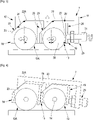
Fig.2 ] représente schématiquement et en coupe d'un premier mode de réalisation d'un dispositif de roulement conforme à l'invention comportant deux galets roulement ; - [
Fig.3 ] est un schéma de principe du fonctionnement des moyens de réglage vertical associés à ce mode de réalisation de lafigure 2 ; - [
Fig.4 ] est un schéma de principe du fonctionnement des moyens de réglage vertical associés à ce mode de réalisation desfigures 2 et3 .
- [
Fig.1 ] schematically represents a window including at least one opening and sliding in a fixed frame; - [
Fig.2 ] shows schematically and in section a first embodiment of a rolling device according to the invention comprising two running rollers; - [
Fig.3 ] is a block diagram of the operation of the vertical adjustment means associated with this embodiment of thefigure 2 ; - [
Fig.4 ] is a block diagram of the operation of the vertical adjustment means associated with this embodiment of thefigure 2 and3 .
Tel que représenté dans la
L'invention a trait, plus particulièrement, à un dispositif de roulement 4 destiné à équiper un tel ouvrant coulissant 2 au niveau de sa traverse inférieure 5 pour reposer, de manière coulissante, sur la traverse inférieure correspondante 6 du cadre dormant 3.The invention relates, more particularly, to a
Très souvent, un tel dispositif de roulement 4 est engagé dans un profil en forme de rail ménagé en feuillure de cette traverse inférieure 5 de l'ouvrant 2, étant entendu que la présente invention n'est nullement limitée à une telle conception.Very often, such a
En se référant à présent aux
Ce boîtier 7 accueille au moins deux cages 13 ; 13A dans lesquelles est monté en rotation autour d'un axe horizontal 14 un galet de roulement 15. Là encore, une cage 13; 13A comporte deux parois longitudinales parallèles 16, 17, reliées, à leurs extrémités, par un premier côté d'extrémité 18 et un second côté d'extrémité 19.This
Selon l'invention, une cage 13 ; 13A est montée dans le boîtier 7 mobile en translation dans au moins une direction verticale 20 et dans une direction horizontale 21 perpendiculaire à l'axe de rotation 14 du galet de roulement 15. Cette direction horizontale 21 correspond sensiblement à l'axe longitudinal du boîtier 7 et à la direction de déplacement de l'ouvrant coulissant 2 dans son cadre dormant 3.According to the invention, a
Le boîtier 7 comporte encore au moins une rampe d'appui inclinée 22 ; 22A avec laquelle vient en applique une surface d'appui 23 d'inclinaison sensiblement identique que comporte une cage 13 ; 13A au moins au niveau de son premier côté d'extrémité 18.The
Selon un exemple de réalisation, au niveau de ce premier côté d'extrémité 18, les parois longitudinales 16, 17 de cette cage 13 ; 13A comportent, dans leur partie supérieure, des coupes en biais 24 dont le chant 25 vient définir cette surface d'appui 23 conçue pour coopérer avec une rampe d'appui inclinée 22 ; 22A ménagée intérieurement aux parois longitudinales 8, 9 du boîtier 7.According to an exemplary embodiment, at this
Ainsi, ces rampes 22 ; 22A peuvent s'étendre entre ces parois longitudinales 8, 9, tout comme elle peuvent être définies par des portions de rampe que comportent, en face-à-face, ces parois longitudinales 8, 9 du boîtier 7, comme illustré dans les dessins, et dont une portion de rampe coopère avec la coupe en biais 24 de la paroi longitudinale 16 et dont l'autre avec celle de la paroi longitudinale 17, coupes en biais 24 définissant, chacune, une surface d'appui 23.Thus, these
Selon l'invention, une cage 13 ; 13A comporte sur son second côté d'extrémité 19, opposé au premier 18, une face d'appui sensiblement verticale 26 coopérant, selon le cas, avec une face d'appui complémentaire 27 que comporte le boitier 7, ou un premier côté d'extrémité 18 d'une cage 13A adjacente.According to the invention, a
De manière avantageuse, le dispositif de roulement 4 comporte des moyens 29 de réglage vertical d'au moins une cage 13 ; 13A dans le boitier 7. En particulier, au travers de tels moyens de réglage 29 il est possible d'ajuster l'accostage, autrement dit l'équerrage d'un ouvrant coulissant 2 par rapport à son cadre dormant 3.Advantageously, the
Selon un mode de réalisation préférentiel de l'invention, ces moyens de réglage vertical 29 sont définis sous forme de moyens d'ajustement de la distance 30 entre une face d'appui complémentaire 27 dans le boîtier 7 et au moins une rampe d'appui inclinée 22 ; 22A correspondant à un logement de réception 28 d'une cage 13.According to a preferred embodiment of the invention, these vertical adjustment means 29 are defined in the form of means for adjusting the
En se référant aux figures, les moyens de réglage vertical 29 sont définis par une face d'appui complémentaire 27 ajustable en position dans le boîtier 7 par translation longitudinale pour moduler sa distance 30 par rapport à la rampe d'appui inclinée 22. Ainsi, en agissant sur cette distance 30, par exemple en rapprochant la face d'appui complémentaire 27 de cette rampe d'appui inclinée 22 à l'aide d'une vis de réglage 31, l'interaction entre cette rampe d'appui inclinée 22 et la surface d'appui d'inclinaison similaire 23 que comporte au niveau de son premier côté d'extrémité 18 une cage 13, celle-ci est repoussée vers le bas.Referring to the figures, the vertical adjustment means 29 are defined by a
On comprend que, dans une situation montée sur un ouvrant coulissant 2, une telle action sur le dispositif de roulement 4 a pour conséquence de soulever l'ouvrant 2 par rapport au cadre dormant 3.It is understood that, in a situation mounted on a sliding
Évidemment, une action contraire conduisant à augmenter cette distance 30, a pour conséquence la remontée de la cage 13 dans le logement 28 du boîtier 7 et l'affaissement de l'ouvrant 2.Obviously, a contrary action leading to increase this
Les
Dans cette configuration, la face d'appui vertical 26 sur le second côté d'extrémité 19 de la première cage 13 vient en appui sur une face d'appui complémentaire 27 que comporte intérieurement le boîtier 7.In this configuration, the vertical support face 26 on the
Cette surface d'appui complémentaire 27 est ajustable en position dans le boîtier 7 par translation longitudinale pour moduler sa distance 30 par rapport aux rampes d'appui inclinées 22, 22A. Ainsi, comme souhaite l'illustrer la
À noter, toutefois, que les cages 13 et 13A, étant en contact et non reliées entre elles, sont individuellement mobiles verticalement dans le boîtier 7. Cette particularité a pour conséquence de permettre au boîtier 7 de pivoter autour d'un axe sensiblement parallèle à l'axe 14 de pivotement des galets 15. En somme, ce boîtier 7 peut adopter une position inclinée par rapport au plan d'appui de ces galets 15 sur leur rail au niveau de la traverse inférieure 6 du cadre dormant 3. Cette situation, illustrée schématiquement dans la
Comme il ressort de la description qui précède et, plus particulièrement, des caractéristiques de la présente invention, celle-ci conduit à un dispositif de roulement 4 pour ouvrant coulissant 2 répondant à l'ensemble des inconvénients de l'état antérieur de la technique. En particulier, cette solution selon l'invention évite le montage pivotant d'une cage 13 à galet 15 dans le boîtier 7 de ce dispositif de roulement 4, montage, non seulement complexe, mais sujet à dysfonctionnement dans le temps.As emerges from the preceding description and, more particularly, from the characteristics of the present invention, the latter leads to a rolling
De plus ces cages à galet 13 ; 13A sont standards et sont en mesure de venir se loger par simple emboitement dans un boitier 7 d'un dispositif de roulement 4 à galet unique ou double.In addition these
A noter à ce propos, qu'une cage à galet 13 ; 13A peut être maintenue, après montage dans le boitier 7, par l'intermédiaire de moyens de retenue adaptés (non représentés), tels des moyens de clippage ou similaire, pour éviter qu'elle ne retombe de ce boitier 7, notamment au moment d'équiper un ouvrant coulissant 2 d'un dispositif de roulement 4 selon l'invention, ou encore au moment du montage de cet ouvrant 2 sur son cadre dormant 3.Note in this regard that a
Claims (7)
Applications Claiming Priority (1)
| Application Number | Priority Date | Filing Date | Title |
|---|---|---|---|
| FR2101203A FR3119634B1 (en) | 2021-02-09 | 2021-02-09 | Rolling device for sliding sash of door or window |
Publications (1)
| Publication Number | Publication Date |
|---|---|
| EP4039929A1 true EP4039929A1 (en) | 2022-08-10 |
Family
ID=75539521
Family Applications (1)
| Application Number | Title | Priority Date | Filing Date |
|---|---|---|---|
| EP22155786.1A Pending EP4039929A1 (en) | 2021-02-09 | 2022-02-09 | Rolling device for sliding leaf of a door or window |
Country Status (2)
| Country | Link |
|---|---|
| EP (1) | EP4039929A1 (en) |
| FR (1) | FR3119634B1 (en) |
Citations (3)
| Publication number | Priority date | Publication date | Assignee | Title |
|---|---|---|---|---|
| EP1854948A2 (en) * | 2006-05-08 | 2007-11-14 | ERRETI S.r.l. | Carriage |
| WO2011000788A1 (en) | 2009-06-29 | 2011-01-06 | Aesculap Ag | Surgical thread comprising cells and method of manufacturing the thread |
| WO2011100788A1 (en) * | 2010-02-17 | 2011-08-25 | Camlock Engineering Pty Ltd | Adjustable carriage |
-
2021
- 2021-02-09 FR FR2101203A patent/FR3119634B1/en active Active
-
2022
- 2022-02-09 EP EP22155786.1A patent/EP4039929A1/en active Pending
Patent Citations (3)
| Publication number | Priority date | Publication date | Assignee | Title |
|---|---|---|---|---|
| EP1854948A2 (en) * | 2006-05-08 | 2007-11-14 | ERRETI S.r.l. | Carriage |
| WO2011000788A1 (en) | 2009-06-29 | 2011-01-06 | Aesculap Ag | Surgical thread comprising cells and method of manufacturing the thread |
| WO2011100788A1 (en) * | 2010-02-17 | 2011-08-25 | Camlock Engineering Pty Ltd | Adjustable carriage |
Also Published As
| Publication number | Publication date |
|---|---|
| FR3119634A1 (en) | 2022-08-12 |
| FR3119634B1 (en) | 2023-04-28 |
Similar Documents
| Publication | Publication Date | Title |
|---|---|---|
| WO2019081446A1 (en) | Mechanism for opening/closing an opening leaf with respect to a frame | |
| EP0846826B1 (en) | Rolling device for sliding door | |
| EP4039929A1 (en) | Rolling device for sliding leaf of a door or window | |
| EP3401484B1 (en) | Building openings such as doors or windows with sliding-lifting leaf and damping device | |
| EP0044799B1 (en) | Fitting for sliding windows, sliding doors or the like | |
| FR3044700A1 (en) | CLOSURE DEVICE | |
| FR3051821A1 (en) | SECTIONAL DOOR COMPRISING A PORTILLON AND A MECHANICAL PASSIVE SAFETY DEVICE FOR PREVENTING AND / OR LIMITING THE OPENING OF THE PORTILLON IN THE OPEN POSITION OF THE VANTAIL OF SUCH A DOOR. | |
| EP2042372A1 (en) | Tilting-sliding loading bed device for breakdown vehicle. | |
| BE1004648A6 (en) | Truck carrier for sliding doors and windows. | |
| FR2718165A1 (en) | Tilting barrier drive mechanism for e.g. tolls, car=parks | |
| FR2883907A1 (en) | Motorized sliding door way position regulator device for e.g. industrial buildings, has support unit integrated to apron by support, where unit is arranged to receive engine block and its coupling unit to couple to steering rack | |
| EP1160413A1 (en) | Method for disassembling and reassembling of a frame and a roller shutter box, assembly formed by a frame, a roller shutter box and an end console from that roller shutter box | |
| FR3043122A1 (en) | DEVICE AND METHOD FOR AUTOMATING A DOOR | |
| EP2288775B1 (en) | Closing system with sliding leaves | |
| FR2920814A1 (en) | DIPOSITIVE AUTO LOCKING FOR SHUTTER APRON | |
| FR3027619A1 (en) | AESTHETIC SWIVEL PORTAL AND RELIABLE | |
| EP1050656B1 (en) | Automatic gate with swinging wing | |
| FR2797245A1 (en) | Transport vehicle bodywork comprises opening closed by door moved by transmission belt to wind around drum to give access to opening | |
| FR2710945A1 (en) | Self-supporting cantilevered sliding gate | |
| EP2617922B1 (en) | Swinging door device with assisted swinging | |
| FR3074127B1 (en) | PALLET DOOR MODULE WITH A HIGH GUIDE SYSTEM | |
| FR2488322A1 (en) | Reversible skylight with sash frame set in portal frame - uses hinges to mount portal frame and to fix sash in open end of portal | |
| FR2844541A1 (en) | DEVICE FOR SEALING A SLIDING DOOR | |
| FR2886331A1 (en) | METHOD FOR INSTALLING A SHUTTER BLOCK AND A SUPPORT TAQUET FOR ITS IMPLEMENTATION | |
| FR3085703A1 (en) | TILTING GARAGE DOOR WITHOUT EDGE AND WITHOUT CEILING RAIL |
Legal Events
| Date | Code | Title | Description |
|---|---|---|---|
| PUAI | Public reference made under article 153(3) epc to a published international application that has entered the european phase |
Free format text: ORIGINAL CODE: 0009012 |
|
| STAA | Information on the status of an ep patent application or granted ep patent |
Free format text: STATUS: THE APPLICATION HAS BEEN PUBLISHED |
|
| AK | Designated contracting states |
Kind code of ref document: A1 Designated state(s): AL AT BE BG CH CY CZ DE DK EE ES FI FR GB GR HR HU IE IS IT LI LT LU LV MC MK MT NL NO PL PT RO RS SE SI SK SM TR |
|
| STAA | Information on the status of an ep patent application or granted ep patent |
Free format text: STATUS: REQUEST FOR EXAMINATION WAS MADE |
|
| 17P | Request for examination filed |
Effective date: 20221221 |
|
| RBV | Designated contracting states (corrected) |
Designated state(s): AL AT BE BG CH CY CZ DE DK EE ES FI FR GB GR HR HU IE IS IT LI LT LU LV MC MK MT NL NO PL PT RO RS SE SI SK SM TR |
|
| P01 | Opt-out of the competence of the unified patent court (upc) registered |
Effective date: 20230720 |
|
| GRAP | Despatch of communication of intention to grant a patent |
Free format text: ORIGINAL CODE: EPIDOSNIGR1 |
|
| STAA | Information on the status of an ep patent application or granted ep patent |
Free format text: STATUS: GRANT OF PATENT IS INTENDED |
|
| INTG | Intention to grant announced |
Effective date: 20240314 |