EP4039913B1 - Baustütze - Google Patents
Baustütze Download PDFInfo
- Publication number
- EP4039913B1 EP4039913B1 EP22165642.4A EP22165642A EP4039913B1 EP 4039913 B1 EP4039913 B1 EP 4039913B1 EP 22165642 A EP22165642 A EP 22165642A EP 4039913 B1 EP4039913 B1 EP 4039913B1
- Authority
- EP
- European Patent Office
- Prior art keywords
- outer tube
- inner tube
- tube
- longitudinal direction
- construction support
- Prior art date
- Legal status (The legal status is an assumption and is not a legal conclusion. Google has not performed a legal analysis and makes no representation as to the accuracy of the status listed.)
- Active
Links
Images



Classifications
-
- E—FIXED CONSTRUCTIONS
- E04—BUILDING
- E04G—SCAFFOLDING; FORMS; SHUTTERING; BUILDING IMPLEMENTS OR AIDS, OR THEIR USE; HANDLING BUILDING MATERIALS ON THE SITE; REPAIRING, BREAKING-UP OR OTHER WORK ON EXISTING BUILDINGS
- E04G25/00—Shores or struts; Chocks
- E04G25/04—Shores or struts; Chocks telescopic
- E04G25/06—Shores or struts; Chocks telescopic with parts held together by positive means
- E04G25/065—Shores or struts; Chocks telescopic with parts held together by positive means by a threaded nut
-
- E—FIXED CONSTRUCTIONS
- E04—BUILDING
- E04C—STRUCTURAL ELEMENTS; BUILDING MATERIALS
- E04C3/00—Structural elongated elements designed for load-supporting
- E04C3/30—Columns; Pillars; Struts
- E04C3/32—Columns; Pillars; Struts of metal
-
- F—MECHANICAL ENGINEERING; LIGHTING; HEATING; WEAPONS; BLASTING
- F16—ENGINEERING ELEMENTS AND UNITS; GENERAL MEASURES FOR PRODUCING AND MAINTAINING EFFECTIVE FUNCTIONING OF MACHINES OR INSTALLATIONS; THERMAL INSULATION IN GENERAL
- F16B—DEVICES FOR FASTENING OR SECURING CONSTRUCTIONAL ELEMENTS OR MACHINE PARTS TOGETHER, e.g. NAILS, BOLTS, CIRCLIPS, CLAMPS, CLIPS OR WEDGES; JOINTS OR JOINTING
- F16B7/00—Connections of rods or tubes, e.g. of non-circular section, mutually, including resilient connections
- F16B7/18—Connections of rods or tubes, e.g. of non-circular section, mutually, including resilient connections using screw-thread elements
- F16B7/182—Connections of rods or tubes, e.g. of non-circular section, mutually, including resilient connections using screw-thread elements for coaxial connections of two rods or tubes
-
- F—MECHANICAL ENGINEERING; LIGHTING; HEATING; WEAPONS; BLASTING
- F16—ENGINEERING ELEMENTS AND UNITS; GENERAL MEASURES FOR PRODUCING AND MAINTAINING EFFECTIVE FUNCTIONING OF MACHINES OR INSTALLATIONS; THERMAL INSULATION IN GENERAL
- F16B—DEVICES FOR FASTENING OR SECURING CONSTRUCTIONAL ELEMENTS OR MACHINE PARTS TOGETHER, e.g. NAILS, BOLTS, CIRCLIPS, CLAMPS, CLIPS OR WEDGES; JOINTS OR JOINTING
- F16B7/00—Connections of rods or tubes, e.g. of non-circular section, mutually, including resilient connections
- F16B7/10—Telescoping systems
- F16B7/14—Telescoping systems locking in intermediate non-discrete positions
Definitions
- the invention relates to a prop, with an axial longitudinal direction, a circumferential direction concentric thereto and a radial direction, with an outer tube extending in the longitudinal direction, an inner tube arranged therein which extends in the longitudinal direction and is adjustable relative to the outer tube in the longitudinal direction and has an external thread
- the outer pipe is an out-of-round rolled pipe and the outer pipe is provided with at least one guide groove extending in the longitudinal direction and opening radially inwards during the course of the rolling production, the inner pipe having at least one guide element projecting radially outwards, which fits into the guide groove which opens radially inwards guide groove engages, so that the inner pipe is thus arranged in the circumferential direction in a form-fitting, non-rotatable manner in the outer pipe, with an adjusting nut having an internal thread that can be screwed to the external thread of the inner pipe being arranged in a longitudinal end region of the outer pipe in a captive manner but rotatable in the circumferential direction, with turning the
- props are off DE 10 2012 211384 A1 , WO 2007/039422 A2 or DE 195 03 296 A1 known.
- the present invention is based on the object of creating a prop that is stable and easy to handle and can be produced inexpensively.
- the inner tube is a round tube and the foldable means are formed by welding on flange-like sections or are formed in one piece from the material of the outer tube by a radially outward deformation.
- the outer tube is manufactured inexpensively in a rolling process.
- the tube is provided with at least one guide groove which opens radially inwards and extends in the longitudinal direction. Due to the guide groove, the outer tube has a non-round profile for receiving the guide element. As a result, the inner tube is prevented from rotating in the outer tube.
- the inner tube is adjusted in the longitudinal direction relative to the outer tube, and thus the longitudinal adjustment of the prop, by turning the adjusting nut.
- the inner tube is thereby adjusted translationally in the longitudinal direction relative to the outer tube, with the guide element of the inner tube sliding axially in the guide groove of the outer tube.
- the inner tube is fixed in the axial longitudinal direction by the adjusting nut, and an undesired translatory inward or outward movement of the inner tube into or out of the outer tube is reliably prevented.
- the outer tube is made from a steel alloy and is preferably galvanized to protect against corrosion.
- the inner tube is preferably made from a steel alloy. It proves advantageous if the inner tube is also manufactured in a rolling process and in a galvanized version.
- the external thread of the inner tube is advantageously produced in a non-cutting shaping process, in particular a thread rolling process or a thread rolling process.
- the outer tube comprises several, preferably two, three or four guide grooves extending in the longitudinal direction, and that the inner tube accordingly has several, preferably two, three or four guide elements engaging in these guide grooves. Due to the guide elements engaging in the guide grooves, the inner tube is arranged in the outer tube in a non-rotatable manner in the circumferential direction.
- the guide element of the inner tube can be implemented in many ways. It is conceivable that the guide element is formed by adding material, for example by welding on wing-like expansion elements.
- the guide element is preferably formed by a radially outwardly directed deformation of the material of the inner tube, for example by punctiform material deformation in the form of a wart that is pressed radially outward.
- the guide element is formed in one piece from the material of the inner tube by cutting and widening or bending radially outwards.
- the guide element is formed by at least one, preferably two, pins.
- the pins are pushed through a respective opening in the inner tube and protrude radially outwards.
- the guide element is formed in or on a longitudinal end area of the inner pipe arranged in the outer pipe.
- this longitudinal end portion of the inner pipe extends from an end of the inner pipe arranged in the outer pipe over 30 cm in the longitudinal direction, and the guide element is arranged inside the longitudinal end area.
- the external thread of the inner tube is limited by a spot weld or pinch.
- a thread-free part is provided on the inner tube.
- the external thread ends in an area of at least 30 cm before the end of the inner tube.
- the adjusting nut is captively arranged on the outer tube.
- the adjusting nut is arranged on the outer tube by means of a securing element in a form-fitting manner in the axial direction, but is subject to play and is rotatable in the circumferential direction.
- the securing element is held in a form-fitting manner on the outer tube in the axial direction. It is conceivable that the securing element is held on the outer tube, e.g.
- the securing element can be implemented in various ways and can be shaped in various ways, for example U-shaped. In an embodiment that is not claimed, however, the securing element is a securing ring that encompasses the outer tube.
- the outer tube has a support section in the longitudinal end area for contacting the securing element from axially below.
- the support section can be realized in various ways, in particular by adding material, for example by welding on wing-like or ring-shaped extension pieces.
- the support section is preferably formed by a radially outwardly directed deformation of material of the outer tube.
- the support section is particularly preferably formed in one piece from the material of the outer tube, preferably by cutting and bending. It is quite conceivable that the adjusting nut is seated on the support section of the outer tube from axially above.
- the adjusting nut After inserting the inner tube into the outer tube, the adjusting nut is positively connected to the securing element.
- the securing element has at least one shoulder that can be folded over radially inwards into an axial position that engages behind the adjusting nut. It is conceivable that the projection of the securing element, which can be folded over radially inwards, is crimped with an edge of the adjusting nut.
- the shoulder which can be folded over radially inwards, preferably engages in a circumferential groove of the adjusting nut in a form-fitting manner.
- the longitudinal end area of the outer tube itself forms a securing element for the adjusting nut.
- the longitudinal end area has means that can be folded over.
- the foldable means are formed by welding on flange-like sections.
- the foldable means are formed in one piece from the material of the outer tube by a radially outwardly directed deformation.
- the foldable means of the longitudinal end area are of at least one radially outwardly projecting section with at least an approach that can be folded over radially inwards into an axial gripping position with the adjusting nut.
- the shoulder which can be folded over radially inwards, preferably engages in a peripheral groove of the adjusting nut.
- the adjusting nut comprises several, preferably three or four, tool attachment points, in particular wing-like hammer stop surfaces.
- the outer tube and the inner tube have a receptacle for a base plate and a head plate and the base and head plate is designed in such a way that another foot and head part is attached to it, in particular centrally can be.
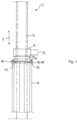
- the figures show a prop, designated overall by the reference numeral 2, with an axial longitudinal direction 4, a circumferential direction 6 concentric thereto and a radial direction 8.
- the prop 2 comprises an outer tube 10 extending in the longitudinal direction 4 and an inner tube 12 arranged therein
- Prop 2 has an adjusting nut 14, which is captive in a longitudinal end region 16 of the outer tube 10 in a manner to be described in more detail, but in the circumferential direction 6 is rotatably arranged and. by means of which the inner tube 12 can be adjusted in the axial longitudinal direction 4 relative to the outer tube 10 .
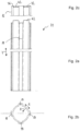
- the outer tube 10 is in the course of rolling production with at least one and according to a preferred embodiment according to Figures 2a and 2b provided with four longitudinal guide grooves 18 extending in the axial direction 4 and as a result has a non-round profile.
- the longitudinal guide grooves 18 open radially inwards and are offset by 90° to one another. If two or three longitudinal guide grooves 18 are provided, it can be expedient for reasons of symmetry to arrange them diametrically opposite or offset by 120° from one another.
- the inner tube 12 is a round tube with an external thread 20. It is according to a preferred embodiment Figures 3a and 3b provided in a thread-free longitudinal end area 22 with four radially outwardly projecting guide elements 24.
- the guide elements 24 are offset by 90° to one another in accordance with the longitudinal guide grooves 18 .
- the guide elements 24 are formed in one piece from the material of the inner tube 12 by cutting at a lower edge 26 and bending radially inwards. If the inner tube 12 is inserted into the outer tube 10, the guide elements 24 engage in the longitudinal guide grooves 18 from radially inside. As a result, the inner tube 12 is arranged in the outer tube 10 so that it cannot rotate.
- the guide elements 24 are formed by two pins 54 .
- the pins 54 are pushed through a respective opening 56 in the inner tube 12 and protrude radially outwards. If the inner tube 12 is inserted into the outer tube 10, the radially outwardly protruding pins 54 engage from radially inwards the longitudinal guide grooves 18. As a result, the inner tube 12 is arranged in the outer tube 10 so that it cannot rotate.
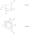
- the adjusting nut 14 includes an internal thread 28 that can be screwed onto the external thread 20 of the inner tube 12 and a circumferential groove 30. According to a preferred embodiment, the adjusting nut 14 also includes Figure 4b several, in particular three, tool attachment points 32. Wing-like hammer stop surfaces have proven to be advantageous.
- figure 5 shows the prop 2 according to the invention, the inner tube 12 being arranged in the outer tube 10 .
- the adjusting nut 14 is screwed onto the inner tube and is seated according to the in figure 5 shown position with a lower end 34 on an upper end 36 in the longitudinal end portion 16 of the outer tube 10.
- the guide elements 24 of the inner tube 12 engage in the longitudinal guide grooves 18 of the outer tube 10 .
- the guide elements 24 slide in the longitudinal guide grooves 18, as a result of which the inner tube 12 moves translationally relative to the outer tube 10 by turning the adjusting nut 14.
- the in the inner tube 12 screwed into the adjusting nut 14 is fixed by the adjusting nut 14 in the axial longitudinal direction 4, since the adjusting nut 14 is held captively on the outer tube 10 in a manner to be described in more detail below. Undesirable translatory inward or outward movement of the inner tube 12 into or out of the outer tube 10 is prevented, since the inner tube 12 can only be adjusted in the longitudinal direction 4 by turning the adjusting nut 14 .
- the adjusting nut 14 is according to figure 1 by means of a locking ring 38 in a form-fitting manner in the axial direction, but with play and rotatably arranged on the outer tube 10 in the circumferential direction.
- the retaining ring 38 includes the outer tube 10 and has according to Figure 6b one with the non-round profile of Outer tube 10 cooperating inner profile 40 on.
- the illustrated versions with the locking ring 38 are not claimed, but serve for better understanding.
- support sections 42 are provided on the outer tube 10 .
- Figures 2a and 2c show the support sections 42 in the longitudinal end region 16 of the outer tube 10.
- the support sections 42 are preferably formed in one piece from material of the outer tube.
- the outer tube 10 is cut from axially above in the area between the longitudinal guide grooves 18 so that four tongue-like sections remain. These are bent in such a way that they form support sections 42 protruding radially outwards.
- the locking ring 38 is first pushed onto the outer tube from axially above and then the support sections 42 are formed, so that the locking ring 38 bears against the support sections 42 from axially below.
- the adjusting nut 14 sits on the support sections 42 from above axially and the projections 44 of the retaining ring 38 that can be folded radially inwards are bent radially inward in such a way that the projections 44 engage in a circumferential groove 30 of the adjusting nut 14 .
- the adjusting nut 14 is thus captively held on the outer tube 10 by the retaining ring resting against the support sections 42 from axially below and by the projections 44 of the retaining ring engaging in the circumferential groove 30 .
- the projections 44 engage in the circumferential groove 30 with play such that the adjusting nut 14 can be rotated in the circumferential direction 6 and the inner tube 12 can be adjusted in the longitudinal direction 4 by turning the adjusting nut 14 relative to the outer tube 10 .
- the securing element 46 is formed by the longitudinal end area 16 of the outer tube 10 .
- the Figures 6c and 6d show the longitudinal end area 16 of the outer tube with foldable means 48.
- the outer tube 10 is cut from axially above in the area between the longitudinal guide grooves 18, so that several foldable means 48 remain. These are bent in such a way that they form sections 50 projecting radially outwards with projections 52 which can be folded over radially inwards.
- the projections 52 which can be folded radially inwards, engage in the circumferential groove 30 with play in such a way that the adjusting nut 14 can be rotated in the circumferential direction 6, and the inner pipe 12 can be adjusted in the longitudinal direction 4 by turning the adjusting nut 14 relative to the outer pipe 10.
Landscapes
- Engineering & Computer Science (AREA)
- Architecture (AREA)
- Mechanical Engineering (AREA)
- General Engineering & Computer Science (AREA)
- Civil Engineering (AREA)
- Structural Engineering (AREA)
- Mutual Connection Of Rods And Tubes (AREA)
- Buildings Adapted To Withstand Abnormal External Influences (AREA)
Description
- Die Erfindung betrifft eine Baustütze, mit einer axialen Längsrichtung, einer dazu konzentrischen Umfangsrichtung und einer radialen Richtung, mit einem in der Längsrichtung erstreckten Außenrohr, einem darin angeordneten in der Längsrichtung erstreckten und gegenüber dem Außenrohr in der Längsrichtung verstellbaren Innenrohr mit einem Außengewinde, wobei das Außenrohr ein unrundes gewalztes Rohr ist und das Außenrohr im Zuge der Walz-Herstellung mit wenigstens einer in der Längsrichtung erstreckten und nach radial innen öffnenden Führungsnut versehen ist, wobei das Innenrohr wenigstens ein nach radial außen vorstehendes Führungselement aufweist, welches in die nach radial innen geöffnete Führungsnut eingreift, sodass das Innenrohr dadurch in Umfangsrichtung formschlüssig verdrehsicher im Außenrohr angeordnet ist, wobei in einem Längsendbereich des Außenrohrs verliersicher, jedoch in Umfangsrichtung drehbar eine Stellmutter mit einem mit dem Außengewinde des Innenrohrs verschraubbaren Innengewinde angeordnet ist, wobei durch Drehen der Stellmutter das Innenrohr relativ zu dem Außenrohr in Längsrichtung verstellbar ist, wobei das Führungselement in der Führungsnut gleitet, wobei der Längsendbereich des Außenrohrs umlegbare Mittel aufweist, die ein Sicherungselement für die Stellmutter bilden, wobei die umlegbaren Mittel des Längsendbereichs des Außenrohrs von einem nach radial außen vorstehenden Abschnitt mit wenigstens einem nach radial innen in einen axialen Hintergriff mit der Stellmutter umlegbaren Ansatz gebildet sind.
- Derartige Baustützen sind in großem Umfang bekannt.
- Baustützen sind beispielsweise aus
DE 10 2012 211384 A1 ,WO 2007/039422 A2 oderDE 195 03 296 A1 bekannt. - Der vorliegenden Erfindung liegt die Aufgabe zugrunde, eine Baustütze zu schaffen, die stabil und bedienungsfreundlich handhabbar und kostengünstig herstellbar ist.
- Diese Aufgabe wird durch eine Baustütze nach Anspruch 1 gelöst. Erfindungsgemäß ist vorgesehen, dass das Innenrohr ein Rundrohr ist und die umlegbaren Mittel durch Anschweißen von flanschartigen Abschnitten ausgebildet sind oder von einer nach radial außen gerichteten Verformung einstückig aus dem Material des Außenrohrs gebildet sind.
- Gemäß der Erfindung ist das Außenrohr kostengünstig in einem Walzverfahren hergestellt. Im Zuge des Walzverfahrens wird das Rohr mit der mindestens einen nach radial innen öffnenden und in Längsrichtung erstreckten Führungsnut versehen. Durch die Führungsnut weist das Außenrohr ein unrundes Profil zur Aufnahme des Führungselements auf. Dadurch ist eine Verdrehsicherung des Innenrohrs in dem Außenrohr realisiert.
- Bei der erfindungsgemäßen Ausbildung der Baustütze erfolgt die Verstellung des Innenrohrs in Längsrichtung relativ zum Außenrohr, und damit die Längsverstellung der Baustütze, durch Drehen der Stellmutter. Das Innenrohr wird dadurch translatorisch in Längsrichtung relativ zu dem Außenrohr verstellt, wobei das Führungselement des Innenrohrs axial in der Führungsnut des Außenrohrs gleitet. Gleichzeitig wird durch die Stellmutter das Innenrohr in axialer Längsrichtung fixiert, und ein unerwünschtes translatorisches Ein- bzw. Ausfallen des Innenrohrs in bzw. aus dem Außenrohr wird sicher verhindert.
- Es erweist sich als besonders vorteilhaft, wenn das Außenrohr aus einer Stahllegierung gefertigt und zum Schutz vor Korrosion vorzugsweise verzinkt ist.
- Das Innenrohr ist vorzugsweise aus einer Stahllegierung gefertigt. Es erweist sich als vorteilhaft, wenn das Innenrohr auch in einem Walzverfahren und in verzinkter Ausführung hergestellt ist.
- Das Außengewinde des Innenrohrs ist vorteilhafterweise in einem spanlosen Formgebungsverfahren, insbesondere einem Gewinde-Walzverfahren oder einem Gewinde-Rollverfahren, hergestellt.
- Es erweist sich als ganz besonders vorteilhaft, dass das Außenrohr mehrere, vorzugsweise zwei, drei oder vier, in der Längsrichtung erstreckte Führungsnuten umfasst, und dass das Innenrohr dementsprechend mehrere, vorzugsweise zwei, drei oder vier, in diese Führungsnuten eingreifende Führungselemente aufweist. Durch die in die Führungsnuten eingreifenden Führungselemente ist das Innenrohr in Umfangsrichtung verdrehsicher im Außenrohr angeordnet.
- Das Führungselement des Innenrohrs kann in vielfacher Weise realisiert sein. Denkbar ist, dass das Führungselement durch Hinzufügen von Material, beispielsweise durch Anschweißen von flügelartigen Erweiterungselementen ausgebildet ist.
- Vorzugsweise ist das Führungselement durch eine nach radial außen gerichtete Verformung von Material des Innenrohrs, zum Beispiel durch punktförmige Materialverformung in Form einer nach radial außen gedrückten Warze, gebildet. Gemäß einer bevorzugten Ausführungsform wird das Führungselement einstückig aus dem Material des Innenrohrs durch Einschneiden und nach radial außen Aufweiten oder Umbiegen geformt.
- Bei einer weiteren bevorzugten Ausführungsform ist das Führungselement von wenigstens einem, vorzugsweise zwei, Stiften gebildet. Die Stifte sind durch eine jeweilige Öffnung im Innenrohr hindurchgesteckt und stehen nach radial außen vor.
- Um eine axiale Verstellbarkeit des Innenrohrs relativ zu dem Außenrohr über eine möglichst große Weglänge zu gewährleisten, erweist es sich als vorteilhaft, dass sich das Außengewinde des Innenrohrs über eine möglichst große Länge des Innenrohrs erstreckt.
- Weiter erweist es sich als besonders vorteilhaft, dass das Führungselement in oder an einem in dem Außenrohr angeordneten Längsendbereich des Innenrohrs ausgebildet ist. Vorzugsweise erstreckt sich dieser Längsendbereich des Innenrohrs von einem, in dem Außenrohr angeordneten Ende des Innenrohrs über 30cm in Längsrichtung und das Führungselement ist innerhalb des Längsendbereichs angeordnet.
- Um ein unbeabsichtigtes Ausdrehen der Stellmutter zu verhindern, ist es denkbar, dass das Außengewinde des Innenrohrs durch einen Schweißpunkt oder Quetschung begrenzt ist. In einer bevorzugten Ausführungsform ist am Innenrohr ein gewindefreier Teil vorgesehen. Insbesondere endet das Außengewinde in einem Bereich von wenigstens 30 cm vor dem Ende des Innenrohrs.
- Wie eingangs erwähnt, ist die Stellmutter verliersicher am Außenrohr angeordnet. Gemäß einer bevorzugten Ausführungsform ist die Stellmutter mittels eines Sicherungselements in axialer Richtung formschlüssig, jedoch spielbehaftet und in Umfangsrichtung drehbar am Außenrohr angeordnet. Das Sicherungselement ist bei einer nicht beanspruchten Ausführungsform in axialer Richtung formschlüssig an dem Außenrohr gehalten. Denkbar ist, dass das Sicherungselement z.B. durch stoffschlüssiges Verbinden, am Außenrohr gehalten ist.
- Das Sicherungselement ist in verschiedener Weise realisierbar und kann verschiedenartig geformt, beispielsweise U-förmig, ausgebildet sein. Bei einer nicht beanspruchten Ausführungsform ist das Sicherungselement aber ein das Außenrohr umfassender Sicherungsring.
- Bei einer nicht beanspruchten Ausführungsform weist das Außenrohr im Längsendbereich einen Stützabschnitt zur Anlage des Sicherungselements von axial unten auf. Der Stützabschnitt kann auf verschiedene Weise, insbesondere durch Hinzufügen von Material, beispielsweise durch Anschweißen von flügelartigen oder ringförmigen Erweiterungsstücken realisiert sein. Vorzugsweise ist der Stützabschnitt durch eine nach radial außen gerichtete Verformung von Material des Außenrohrs gebildet. Besonders bevorzugt ist der Stützabschnitt einstückig aus Material des Außenrohrs, vorzugsweise durch Einschneiden und Umbiegen, gebildet. Es ist durchaus denkbar, dass die Stellmutter auf dem Stützabschnitt des Außenrohrs von axial oben aufsitzt.
- Nach Einführen des Innenrohrs in das Außenrohr, wird die Stellmutter mit dem Sicherungselement formschlüssig verbunden. Vorteilhafterweise weist das Sicherungselement wenigstens einen nach radial innen in eine axiale Hintergriffstellung mit der der Stellmutter umlegbaren Ansatz auf. Denkbar ist, dass der nach radial innen umlegbare Ansatz des Sicherungselements mit einem Rand der Stellmutter aufgebördelt ist. Vorzugsweise greift der nach radial innen umlegbare Ansatz in eine Umfangsnut der Stellmutter formschlüssig ein.
- Erfindungsgemäß bildet der Längsendbereich des Außenrohrs selbst ein Sicherungselement für die Stellmutter. Der Längsendbereich weist dazu umlegbare Mittel auf. Bei einer erfindungsgemäßen Variante ist vorgesehen, dass die umlegbaren Mittel durch Anschweißen von flanschartigen Abschnitten ausgebildet sind. Bei einer anderen erfindungsgemäßen Variante sind die umlegbaren Mittel von einer nach radial außen gerichteten Verformung einstückig aus dem Material des Außenrohrs gebildet.
- Die umlegbaren Mittel des Längsendbereichs sind von wenigstens einem nach radial außen vorstehender Abschnitt mit wenigstens einem nach radial innen in eine axiale Hintergriffstellung mit der Stellmutter umlegbaren Ansatz gebildet. Vorzugsweise greift der nach radial innen umlegbare Ansatz in eine Umfangsnut der Stellmutter ein.
- Ferner erweist es sich als ganz besonders vorteilhaft, wenn die Stellmutter mehrere, vorzugsweise drei oder vier, Werkzeugansetzstellen, insbesondere flügelartige Hammeranschlagflächen, umfasst.
- Für den zweckmäßigen Einsatz der Baustütze erweist es sich als vorteilhaft, wenn das Außenrohr und das Innenrohr eine Aufnahme für eine Fußplatte und eine Kopfplatte aufweisen und die Fuß- und Kopfplatte derart ausgebildet ist, dass ein weiteres Fuß- und Kopfteil, insbesondere zentrisch, daran befestigt werden kann.
- Bevorzugte Weiterbildungen sind in den abhängigen Ansprüchen beschrieben, für die in beliebiger Kombination Schutz in Anspruch genommen wird. Einzelheiten ergeben sich aus der zeichnerischen Darstellung und nachfolgenden Beschreibung eines bevorzugten Ausführungsbeispiels der erfindungsgemäßen Baustütze. In der Zeichnung zeigt:
- Figur 1
- einen Ausschnitt einer Seitenansicht der erfindungsgemäßen Baustütze gemäß einer bevorzugten Ausführungsform;
- Figur 2a
- eine Seitenansicht eines Außenrohrs;
- Figur 2b
- einen Querschnitt durch ein Außenrohr;
- Figur 2c
- eine Detailansicht eines Außenrohrs;
- Figur 3a
- eine Seitenansicht eines Innenrohrs;
- Figur 3b
- einen Querschnitt durch ein Innenrohr;
- Figur 3c
- einen Querschnitt durch ein Innenrohr gemäß einer weiteren Ausführungsform;
- Figur 4a
- eine Seitenansicht einer Stellmutter gemäß einer bevorzugten Ausführungsform;
- Figur 4b
- eine Draufsicht aus axialer Richtung auf eine Stellmutter gemäß
Fig. 4a ; - Figur 5
- eine geschnittene Seitenansicht einer erfindungsgemäßen Baustütze;
- Figur 6a
- eine Seitenansicht eines Sicherungselements gemäß einer bevorzugten Ausführungsform, und
- Figur 6b
- eine Draufsicht aus axialer Richtung auf ein Sicherungselement gemäß
Fig. 6a ; - Figur 6c
- eine Seitenansicht eines Sicherungselements gemäß einer weiteren Ausführungsform;
- Figur 6d
- eine Seitenansicht eines Sicherungselements gemäß
Fig. 6c mit einer Stellmutter; - Figur 7
- eine Seitenansicht der erfindungsgemäßen Baustütze gemäß einer bevorzugten Ausführungsform.
- In den Figuren sind Ausführungsformen der Baustütze gezeigt, die einen Sicherungsring als Sicherungselement zeigen. Diese Ausführungsformen dienen zum besseren Verständnis für die Erfindung, werden aber nicht beansprucht.
- Die Figuren zeigen eine insgesamt mit dem Bezugszeichen 2 bezeichnete Baustütze mit einer axialen Längsrichtung 4, einer dazu konzentrischen Umfangsrichtung 6 und einer radialen Richtung 8. Die Baustütze 2 umfasst ein in der Längsrichtung 4 erstrecktes Außenrohr 10 und ein darin angeordnetes Innenrohr 12. Ferner umfasst die Baustütze 2 eine Stellmutter 14, die in einem Längsendbereich 16 des Außenrohrs 10 auf noch näher zu beschreibende Weise verliersicher, jedoch in Umfangsrichtung 6 drehbar angeordnet ist und. mittels derer das Innenrohr 12 relativ zum Außenrohr 10 in der axialen Längsrichtung 4 verstellbar ist.
- Das Außenrohr 10 ist im Zuge der Walzherstellung mit mindestens einer und nach einer bevorzugten Ausführungsform gemäß den
Figuren 2a und 2b mit vier in axialer Richtung 4 erstreckten Längsführungsnuten 18 versehen und weist dadurch ein unrundes Profil auf. Die Längsführungsnuten 18 öffnen nach radial innen und sind um jeweils 90° versetzt zueinander angeordnet. Sind zwei bzw. drei Längsführungsnuten 18 vorgesehen, kann es aus Symmetriegründen zweckmäßig sein, diese diametral gegenüber bzw. um 120° zueinander versetzt anzuordnen. - Das Innenrohr 12 ist ein Rundrohr mit einem Außengewinde 20. Es ist bei einer bevorzugten Ausführungsform nach
Figuren 3a und 3b in einem gewindefreien Längsendbereich 22 mit vier nach radial außen vorstehenden Führungselementen 24 versehen. Die Führungselemente 24 sind entsprechend den Längsführungsnuten 18 um jeweils 90° versetzt zueinander angeordnet. Die Führungselemente 24 sind einstückig aus Material des Innenrohrs 12 durch Einschneiden an einem unteren Rand 26 und Umbiegen nach radial innen gebildet. Ist das Innenrohr 12 in dem Außenrohr 10 eingesteckt, greifen die Führungselemente 24 von radial innen in die Längsführungsnuten 18 ein. Das Innenrohr 12 ist dadurch verdrehsicher in dem Außenrohr 10 angeordnet. - In einer weiteren bevorzugten Ausführungsform gemäß
Fig. 3c sind die Führungselemente 24 von zwei Stiften 54 gebildet. Die Stifte 54 sind durch eine jeweilige Öffnung 56 im Innenrohr 12 hindurchgesteckt und stehen nach radial außen vor. Ist das Innenrohr 12 in dem Außenrohr 10 eingesteckt, greifen die die nach radial außen vorstehenden Stifte 54 von radial innen in die Längsführungsnuten 18 ein. Das Innenrohr 12 ist dadurch verdrehsicher in dem Außenrohr 10 angeordnet. - Die Stellmutter 14 umfasst ein auf das Außengewinde 20 des Innenrohrs 12 aufschraubbares Innengewinde 28 und eine Umfangsnut 30. Ferner umfasst die Stellmutter 14 gemäß einer bevorzugten Ausführungsform nach
Figur 4b mehrere, insbesondere drei, Werkzeugansetzstellen 32. Als vorteilhaft erweisen sich flügelartige Hammeranschlagsflächen. -
Figur 5 zeigt die erfindungsgemäße Baustütze 2, wobei das Innenrohr 12 in dem Außenrohr 10 angeordnet ist. Die Stellmutter 14 ist auf das Innenrohr aufgeschraubt und sitzt gemäß der inFigur 5 gezeigten Position mit einem unteren Ende 34 auf einem oberen Ende 36 im Längsendbereich 16 des Außenrohrs 10 auf. Die Führungselemente 24 des Innenrohrs 12 greifen in die Längsführungsnuten 18 des Außenrohrs 10 ein. Durch Drehen der Stellmutter 14 verstellt sich das Innenrohr 12 in axialer Längsrichtung 4 relativ zu dem Außenrohr 10. Die Führungselemente 24 gleiten in den Längsführungsnuten 18, dadurch bewegt sich das Innenrohr 12 durch Drehen der Stellmutter 14 translatorisch relativ zum Außenrohr 10. Gleichzeitig wird das in die Stellmutter 14 eingeschraubte Innenrohr 12, von der Stellmutter 14 in axialer Längsrichtung 4 fixiert, da die Stellmutter 14 auf noch näher zu beschreibende Weise verliersicher am Außenrohr 10 gehalten ist. Ein unerwünschtes translatorisches Ein- bzw. Ausfallen des Innenrohrs 12 in bzw. aus dem Außenrohr 10 verhindert, da sich das Innenrohr 12 nur über das Drehen der Stellmutter 14 in Längsrichtung 4 verstellen lässt. - Die Stellmutter 14 ist gemäß
Figur 1 mittels eines Sicherungsrings 38 in axialer Richtung formschlüssig, jedoch spielbehaftet und in Umfangsrichtung drehbar am Außenrohr 10 angeordnet. Der Sicherungsring 38 umfasst das Außenrohr 10 und weist gemäßFigur 6b ein mit dem unrunden Profil des Außenrohrs 10 zusammenwirkendes Innenprofil 40 auf. Die dargestellten Ausführungen mit dem Sicherungsring 38 werden nicht beansprucht, aber dienen dem besseren Verständnis. - Bei einer nicht beanspruchten Ausführungsform sind am Außenrohr 10 Stützabschnitte 42 vorgesehen. Insbesondere die
Figuren 2a und 2c zeigen die Stützabschnitte 42 im Längsendbereich 16 des Außenrohrs 10. Vorzugsweise sind die Stützabschnitte 42 einstückig aus Material des Außenrohrs gebildet. Das Außenrohr 10 wird von axial oben im Bereich zwischen den Längsführungsnuten 18 eingeschnitten, sodass vier zungenartige Abschnitte stehen bleiben. Diese werden derart gebogen, dass sie nach radial außen abstehende Stützabschnitte 42 bilden. Vorzugsweise wird zuerst der Sicherungsring 38 von axial oben auf das Außenrohr gesteckt und anschließend die Stützabschnitte 42 ausgebildet, sodass der Sicherungsring 38 von axial unten an den Stützabschnitten 42 anliegt. Ist das Innenrohr 12 mit der aufgeschraubten Stellmutter 14 gemäßFigur 1 in dem Außenrohr positioniert, sitzt die Stellmutter 14 von axial oben auf den Stützabschnitten 42 auf und die nach radial innen umlegbaren Ansätze 44 des Sicherungsrings 38 werden derart nach radial innen gebogen, dass die Ansätze 44 in eine Umfangsnut 30 der Stellmutter 14 eingreifen. Die Stellmutter 14 ist also über den von axial unten an den Stützabschnitten 42 anliegenden Sicherungsring und über die in die Umfangsnut 30 eingreifenden Ansätze 44 des Sicherungsrings verliersicher am Außenrohr 10 gehalten. Die Ansätze 44 greifen derart spielbehaftet in die Umfangsnut 30 ein, sodass die Stellmutter 14 in Umfangsrichtung 6 verdrehbar ist, und das Innenrohr 12 durch Drehen der Stellmutter 14 relativ zum Außenrohr 10 in Längsrichtung 4 verstellbar ist. - Gemäß einer bevorzugten Ausführungsform ist das Sicherungselement 46 von dem Längsendbereich 16 des Außenrohrs 10 gebildet. Die
Fig. 6c und 6d zeigen den Längsendbereich 16 des Außenrohrs mit umlegbaren Mittel 48. Das Außenrohr 10 wird von axial oben im Bereich zwischen den Längsführungsnuten 18 eingeschnitten, sodass mehrere umlegbare Mittel 48 stehen bleiben. Diese werden derart gebogen, dass sie nach radial außen stehende Abschnitte 50 mit nach radial innen umlegbaren Ansätzen 52 bilden. Die nach radial innen umlegbaren Ansätze 52 greifen derart spielbehaftet in die Umfangsnut 30 ein, sodass die Stellmutter 14 in Umfangsrichtung 6 verdrehbar ist, und das Innenrohr 12 durch Drehen der Stellmutter 14 relativ zum Außenrohr 10 in Längsrichtung 4 verstellbar ist.
Claims (9)
- Baustütze (2), mit einer axialen Längsrichtung (4), einer dazu konzentrischen Umfangsrichtung (6) und einer radialen Richtung (8), mit einem in der Längsrichtung (4) erstreckten Außenrohr (10), einem darin angeordneten in der Längsrichtung (4) erstreckten und gegenüber dem Außenrohr (10) in der Längsrichtung (4) verstellbaren Innenrohr (12) mit einem Außengewinde (20), wobei das Außenrohr (10) ein unrundes gewalztes Rohr ist und das Außenrohr (10) im Zuge der Walz-Herstellung mit wenigstens einer in der Längsrichtung (4) erstreckten und nach radial innen öffnenden Führungsnut (18) versehen ist, wobei das Innenrohr (12) wenigstens ein nach radial außen vorstehendes Führungselement (24) aufweist, welches in die nach radial innen geöffnete Führungsnut (18) eingreift, sodass das Innenrohr (12) dadurch in Umfangsrichtung (6) formschlüssig verdrehsicher im Außenrohr (10) angeordnet ist, wobei in einem Längsendbereich (16) des Außenrohrs (10) verliersicher, jedoch in Umfangsrichtung (6) drehbar eine Stellmutter (14) mit einem mit dem Außengewinde (20) des Innenrohrs (12) verschraubbaren Innengewinde (28) angeordnet ist, wobei durch Drehen der Stellmutter (14) das Innenrohr (12) relativ zu dem Außenrohr (10) in Längsrichtung (4) verstellbar ist, wobei das Führungselement (14) in der Führungsnut (18) gleitet, wobei der Längsendbereich (16) des Außenrohrs (10) umlegbare Mittel (48) aufweist, die ein Sicherungselement (46) für die Stellmutter bilden, wobei die umlegbaren Mittel (48) des Längsendbereichs (16) des Außenrohrs (10) von einem nach radial außen vorstehenden Abschnitt (50) mit wenigstens einem nach radial innen in einen axialen Hintergriff mit der Stellmutter (14) umlegbaren Ansatz (52) gebildet sind, dadurch gekennzeichnet, dass das Innenrohr (12) ein Rundrohr ist und die umlegbaren Mittel (48) durch Anschweißen von flanschartigen Abschnitten ausgebildet sind oder von einer nach radial außen gerichteten Verformung einstückig aus dem Material des Außenrohrs (10) gebildet sind.
- Baustütze (2) nach Anspruch 1, dadurch gekennzeichnet, dass das Außenrohr (10) aus einer Stahllegierung gefertigt und vorzugsweise verzinkt ist und/oder dass das Innenrohr (12) vorzugsweise aus einer Stahllegierung gefertigt ist.
- Baustütze (2) nach einem oder mehreren der vorhergehenden Ansprüche, dadurch gekennzeichnet, dass das Außengewinde (20) des Innenrohrs (12) in einem spanlosen Formgebungsverfahren, insbesondere einem Gewinde-Walzverfahren oder einem Gewinde-Rollverfahren, hergestellt ist.
- Baustütze (2) nach einem oder mehreren der vorhergehenden Ansprüche, dadurch gekennzeichnet, dass das Außenrohr (10) mehrere, vorzugsweise zwei, drei oder vier, in der Längsrichtung (4) erstreckte Führungsnuten (18) umfasst, und dass das Innenrohr (12) dementsprechend mehrere, vorzugsweise zwei, drei oder vier, in diese Führungsnuten (18) eingreifende Führungselemente (24) aufweist.
- Baustütze (2) nach einem oder mehreren der vorhergehenden Ansprüche, dadurch gekennzeichnet, dass das Führungselement (24) des Innenrohrs (12) durch eine nach radial außen gerichtete Verformung von Material des Innenrohrs (12) gebildet ist und/oder dass das Führungselement (24) durch Einschneiden und anschließend nach außen Aufweiten oder Umbiegen von Material des Innenrohrs (12) gefertigt ist.
- Baustütze (2) nach einem oder mehreren der vorhergehenden Ansprüche, dadurch gekennzeichnet, dass das Führungselement (24) in oder an einem in dem Außenrohr (10) angeordneten Längsendbereich (22) des Innenrohrs (12) ausgebildet ist.
- Baustütze (2) nach einem oder mehreren der vorhergehenden Ansprüche, dadurch gekennzeichnet, dass das Führungselement (24) von wenigstens einem durch eine Öffnung (56) im Innenrohr (12) hindurchgesteckten und nach radial außen vorstehenden Stift (54) gebildet ist.
- Baustütze (2) nach einem oder mehreren der vorhergehenden Ansprüche, dadurch gekennzeichnet, dass die Stellmutter (14) mehrere, insbesondere drei, Werkzeugansetzstellen (32), insbesondere flügelartige Hammeranschlagflächen, umfasst.
- Baustütze (2) nach einem oder mehreren der vorhergehenden Ansprüche, dadurch gekennzeichnet, dass das Außenrohr (10) und/oder Innenrohr (12) eine Aufnahme für eine Fußplatte und/oder eine Kopfplatte aufweisen und die Fuß- und/oder Kopfplatte derart ausgebildet ist, dass ein weiteres Fuß- und/oder Kopfteil, insbesondere zentrisch, daran befestigt werden kann.
Applications Claiming Priority (3)
| Application Number | Priority Date | Filing Date | Title |
|---|---|---|---|
| DE102015219043.9A DE102015219043A1 (de) | 2015-10-01 | 2015-10-01 | Baustütze |
| PCT/EP2016/073436 WO2017055559A1 (de) | 2015-10-01 | 2016-09-30 | Baustütze |
| EP16774951.4A EP3356618B1 (de) | 2015-10-01 | 2016-09-30 | Baustütze |
Related Parent Applications (1)
| Application Number | Title | Priority Date | Filing Date |
|---|---|---|---|
| EP16774951.4A Division EP3356618B1 (de) | 2015-10-01 | 2016-09-30 | Baustütze |
Publications (2)
| Publication Number | Publication Date |
|---|---|
| EP4039913A1 EP4039913A1 (de) | 2022-08-10 |
| EP4039913B1 true EP4039913B1 (de) | 2023-06-14 |
Family
ID=57044968
Family Applications (2)
| Application Number | Title | Priority Date | Filing Date |
|---|---|---|---|
| EP16774951.4A Active EP3356618B1 (de) | 2015-10-01 | 2016-09-30 | Baustütze |
| EP22165642.4A Active EP4039913B1 (de) | 2015-10-01 | 2016-09-30 | Baustütze |
Family Applications Before (1)
| Application Number | Title | Priority Date | Filing Date |
|---|---|---|---|
| EP16774951.4A Active EP3356618B1 (de) | 2015-10-01 | 2016-09-30 | Baustütze |
Country Status (6)
| Country | Link |
|---|---|
| US (1) | US10190328B2 (de) |
| EP (2) | EP3356618B1 (de) |
| DE (1) | DE102015219043A1 (de) |
| DK (2) | DK4039913T3 (de) |
| FI (1) | FI4039913T3 (de) |
| WO (1) | WO2017055559A1 (de) |
Families Citing this family (1)
| Publication number | Priority date | Publication date | Assignee | Title |
|---|---|---|---|---|
| EP3816367A1 (de) | 2019-10-28 | 2021-05-05 | DOKA GmbH | Schalungsstütze |
Family Cites Families (17)
| Publication number | Priority date | Publication date | Assignee | Title |
|---|---|---|---|---|
| CH348806A (de) * | 1957-01-30 | 1960-09-15 | Rieder Oscar | Baustütze |
| NL9100139A (nl) * | 1991-01-28 | 1992-08-17 | Leeuw Petrus J L De | Afsteunelement voor toepassing in bouwconstructies. |
| DE4201958A1 (de) * | 1992-01-25 | 1993-08-05 | Peri Gmbh | Traggeruest |
| GB2265921B (en) | 1992-04-08 | 1995-05-24 | Sgb Holdings Ltd | Improvements in or relating to a shoring leg |
| DE19503298C2 (de) * | 1995-02-02 | 1997-02-13 | Peri Gmbh | Gewinde und Verfahren zu seiner Herstellung |
| DE19503296C2 (de) * | 1995-02-02 | 1998-10-15 | Peri Gmbh | Teleskopartig verlängerbare Stütze |
| US6349512B1 (en) * | 1998-07-09 | 2002-02-26 | Steel Floors, Llc | Adjustable support post |
| US6467741B1 (en) * | 2001-03-30 | 2002-10-22 | Lung Ching Shih | Steel prop capable of bearing bidirectional applied force |
| US7165361B2 (en) * | 2003-04-24 | 2007-01-23 | Peter Vanagan | Building construction shores |
| GB2407842B (en) * | 2003-11-07 | 2006-03-01 | Sgb Services Ltd | Shoring system comprising a scaffold clamp |
| ITUD20050150A1 (it) * | 2005-09-21 | 2007-03-22 | Pilosio Spa | Dispositivo di sostegno per realizzare casseforme per solai o simili manufatti edili |
| US7761967B2 (en) * | 2006-05-11 | 2010-07-27 | Wilian Holding Company | Method of assembling a shore post leg assembly |
| US8001733B2 (en) * | 2009-12-04 | 2011-08-23 | Min Chen | Adjustable jack post |
| US8973899B2 (en) * | 2011-12-12 | 2015-03-10 | Mark Allen BUCKINGHAM | Jacking pole |
| DE102012211384A1 (de) * | 2012-06-29 | 2014-01-02 | Hofin Gmbh | Stütze für Betonierungsschalungen |
| US10225629B2 (en) * | 2013-11-25 | 2019-03-05 | Chi Hung Louis Lam | System for monitoring condition of adjustable construction temporary supports |
| GB2526883B (en) * | 2014-06-06 | 2021-04-21 | Mmc Innovations Llp | Temporary support & raising device |
-
2015
- 2015-10-01 DE DE102015219043.9A patent/DE102015219043A1/de active Pending
-
2016
- 2016-09-30 WO PCT/EP2016/073436 patent/WO2017055559A1/de not_active Ceased
- 2016-09-30 EP EP16774951.4A patent/EP3356618B1/de active Active
- 2016-09-30 DK DK22165642.4T patent/DK4039913T3/da active
- 2016-09-30 FI FIEP22165642.4T patent/FI4039913T3/en active
- 2016-09-30 DK DK16774951.4T patent/DK3356618T3/da active
- 2016-09-30 EP EP22165642.4A patent/EP4039913B1/de active Active
-
2018
- 2018-04-02 US US15/942,966 patent/US10190328B2/en active Active
Also Published As
| Publication number | Publication date |
|---|---|
| EP4039913A1 (de) | 2022-08-10 |
| DE102015219043A1 (de) | 2017-04-06 |
| EP3356618A1 (de) | 2018-08-08 |
| DK3356618T3 (da) | 2022-06-27 |
| EP3356618B1 (de) | 2022-04-27 |
| US20180223551A1 (en) | 2018-08-09 |
| WO2017055559A1 (de) | 2017-04-06 |
| DK4039913T3 (da) | 2023-08-14 |
| FI4039913T3 (en) | 2023-08-18 |
| US10190328B2 (en) | 2019-01-29 |
Similar Documents
| Publication | Publication Date | Title |
|---|---|---|
| EP2689151B1 (de) | Schraube mit aufdrehsicherung | |
| DE3139121C2 (de) | ||
| EP3981993B1 (de) | Sicherungsscheibe für eine schraubverbindung sowie schraubverbindung | |
| EP1512876A1 (de) | Senkkopfschraube | |
| EP2513391B1 (de) | Teleskopstütze für den baubereich | |
| EP3586018B1 (de) | Befestigungsvorrichtung und befestigungsbaugruppe | |
| EP3403768B1 (de) | Vorrichtung zum biegen eines splints | |
| EP3428353B1 (de) | Wandhalterung für einen sanitärartikel | |
| EP2921757A1 (de) | Profilschelle | |
| DE2854676A1 (de) | Schneckengewindeschelle | |
| EP3516242B1 (de) | Toleranzausgleichselement | |
| EP3411547B1 (de) | Vorreiberverschluss mit einem in unterschiedlicher höhe an einer schliesswelle fixierbaren verschlusselement | |
| DE102004042478A1 (de) | Verfahren zur verdrehsicheren Befestigung eines Funktionselements in einem Bauteil sowie Verbindung zwischen einem Bauteil und einem Funktionselement | |
| EP3356618B1 (de) | Baustütze | |
| EP3057741B1 (de) | Schraubwerkzeug mit richtungsumstellbarem gesperre | |
| EP1905545B1 (de) | Federspanner für Schraubenfedern | |
| WO2005017372A1 (de) | Vorrichtung mit zwei durch eine verbindungsschraube zusammengehaltenen hohlprofilen sowie werkzeug dazu | |
| DE102015013598B4 (de) | Toleranzausgleichselement und zugehörige Kraftfahrzeugkarosserie | |
| EP4487015B1 (de) | Federbügel zur verdrehsicheren aufnahme einer gewindemutter sowie gewindemutteranordnung und spannschelle aufweisend einen derartigen federbügel | |
| EP1775482B1 (de) | Schnellbefestigungselement | |
| DE4128661A1 (de) | Drehverschluss fuer das verbinden von bauteilen | |
| DE19826380B4 (de) | Osteosynthetisches Befestigungssystem | |
| DE1056878B (de) | Befestigungsglied mit unverlierbar zugeordnetem Federring | |
| EP3195987A1 (de) | Werkzeug | |
| DE10314999B3 (de) | Gelenkhülse für eine Schelle |
Legal Events
| Date | Code | Title | Description |
|---|---|---|---|
| PUAI | Public reference made under article 153(3) epc to a published international application that has entered the european phase |
Free format text: ORIGINAL CODE: 0009012 |
|
| STAA | Information on the status of an ep patent application or granted ep patent |
Free format text: STATUS: THE APPLICATION HAS BEEN PUBLISHED |
|
| STAA | Information on the status of an ep patent application or granted ep patent |
Free format text: STATUS: REQUEST FOR EXAMINATION WAS MADE |
|
| AC | Divisional application: reference to earlier application |
Ref document number: 3356618 Country of ref document: EP Kind code of ref document: P |
|
| AK | Designated contracting states |
Kind code of ref document: A1 Designated state(s): AL AT BE BG CH CY CZ DE DK EE ES FI FR GB GR HR HU IE IS IT LI LT LU LV MC MK MT NL NO PL PT RO RS SE SI SK SM TR |
|
| 17P | Request for examination filed |
Effective date: 20220718 |
|
| RBV | Designated contracting states (corrected) |
Designated state(s): AL AT BE BG CH CY CZ DE DK EE ES FI FR GB GR HR HU IE IS IT LI LT LU LV MC MK MT NL NO PL PT RO RS SE SI SK SM TR |
|
| GRAP | Despatch of communication of intention to grant a patent |
Free format text: ORIGINAL CODE: EPIDOSNIGR1 |
|
| STAA | Information on the status of an ep patent application or granted ep patent |
Free format text: STATUS: GRANT OF PATENT IS INTENDED |
|
| INTG | Intention to grant announced |
Effective date: 20230302 |
|
| GRAS | Grant fee paid |
Free format text: ORIGINAL CODE: EPIDOSNIGR3 |
|
| GRAA | (expected) grant |
Free format text: ORIGINAL CODE: 0009210 |
|
| STAA | Information on the status of an ep patent application or granted ep patent |
Free format text: STATUS: THE PATENT HAS BEEN GRANTED |
|
| AC | Divisional application: reference to earlier application |
Ref document number: 3356618 Country of ref document: EP Kind code of ref document: P |
|
| AK | Designated contracting states |
Kind code of ref document: B1 Designated state(s): AL AT BE BG CH CY CZ DE DK EE ES FI FR GB GR HR HU IE IS IT LI LT LU LV MC MK MT NL NO PL PT RO RS SE SI SK SM TR |
|
| REG | Reference to a national code |
Ref country code: CH Ref legal event code: EP |
|
| REG | Reference to a national code |
Ref country code: DE Ref legal event code: R096 Ref document number: 502016015879 Country of ref document: DE |
|
| REG | Reference to a national code |
Ref country code: AT Ref legal event code: REF Ref document number: 1579338 Country of ref document: AT Kind code of ref document: T Effective date: 20230715 |
|
| P01 | Opt-out of the competence of the unified patent court (upc) registered |
Effective date: 20230612 |
|
| REG | Reference to a national code |
Ref country code: DK Ref legal event code: T3 Effective date: 20230811 |
|
| REG | Reference to a national code |
Ref country code: FI Ref legal event code: FGE |
|
| REG | Reference to a national code |
Ref country code: SE Ref legal event code: TRGR |
|
| REG | Reference to a national code |
Ref country code: NO Ref legal event code: T2 Effective date: 20230614 |
|
| REG | Reference to a national code |
Ref country code: LT Ref legal event code: MG9D |
|
| REG | Reference to a national code |
Ref country code: NL Ref legal event code: MP Effective date: 20230614 |
|
| PG25 | Lapsed in a contracting state [announced via postgrant information from national office to epo] |
Ref country code: ES Free format text: LAPSE BECAUSE OF FAILURE TO SUBMIT A TRANSLATION OF THE DESCRIPTION OR TO PAY THE FEE WITHIN THE PRESCRIBED TIME-LIMIT Effective date: 20230614 |
|
| PG25 | Lapsed in a contracting state [announced via postgrant information from national office to epo] |
Ref country code: RS Free format text: LAPSE BECAUSE OF FAILURE TO SUBMIT A TRANSLATION OF THE DESCRIPTION OR TO PAY THE FEE WITHIN THE PRESCRIBED TIME-LIMIT Effective date: 20230614 Ref country code: NL Free format text: LAPSE BECAUSE OF FAILURE TO SUBMIT A TRANSLATION OF THE DESCRIPTION OR TO PAY THE FEE WITHIN THE PRESCRIBED TIME-LIMIT Effective date: 20230614 Ref country code: LV Free format text: LAPSE BECAUSE OF FAILURE TO SUBMIT A TRANSLATION OF THE DESCRIPTION OR TO PAY THE FEE WITHIN THE PRESCRIBED TIME-LIMIT Effective date: 20230614 Ref country code: LT Free format text: LAPSE BECAUSE OF FAILURE TO SUBMIT A TRANSLATION OF THE DESCRIPTION OR TO PAY THE FEE WITHIN THE PRESCRIBED TIME-LIMIT Effective date: 20230614 Ref country code: HR Free format text: LAPSE BECAUSE OF FAILURE TO SUBMIT A TRANSLATION OF THE DESCRIPTION OR TO PAY THE FEE WITHIN THE PRESCRIBED TIME-LIMIT Effective date: 20230614 Ref country code: GR Free format text: LAPSE BECAUSE OF FAILURE TO SUBMIT A TRANSLATION OF THE DESCRIPTION OR TO PAY THE FEE WITHIN THE PRESCRIBED TIME-LIMIT Effective date: 20230915 |
|
| PG25 | Lapsed in a contracting state [announced via postgrant information from national office to epo] |
Ref country code: SK Free format text: LAPSE BECAUSE OF FAILURE TO SUBMIT A TRANSLATION OF THE DESCRIPTION OR TO PAY THE FEE WITHIN THE PRESCRIBED TIME-LIMIT Effective date: 20230614 |
|
| PG25 | Lapsed in a contracting state [announced via postgrant information from national office to epo] |
Ref country code: IS Free format text: LAPSE BECAUSE OF FAILURE TO SUBMIT A TRANSLATION OF THE DESCRIPTION OR TO PAY THE FEE WITHIN THE PRESCRIBED TIME-LIMIT Effective date: 20231014 |
|
| PG25 | Lapsed in a contracting state [announced via postgrant information from national office to epo] |
Ref country code: SM Free format text: LAPSE BECAUSE OF FAILURE TO SUBMIT A TRANSLATION OF THE DESCRIPTION OR TO PAY THE FEE WITHIN THE PRESCRIBED TIME-LIMIT Effective date: 20230614 Ref country code: SK Free format text: LAPSE BECAUSE OF FAILURE TO SUBMIT A TRANSLATION OF THE DESCRIPTION OR TO PAY THE FEE WITHIN THE PRESCRIBED TIME-LIMIT Effective date: 20230614 Ref country code: RO Free format text: LAPSE BECAUSE OF FAILURE TO SUBMIT A TRANSLATION OF THE DESCRIPTION OR TO PAY THE FEE WITHIN THE PRESCRIBED TIME-LIMIT Effective date: 20230614 Ref country code: PT Free format text: LAPSE BECAUSE OF FAILURE TO SUBMIT A TRANSLATION OF THE DESCRIPTION OR TO PAY THE FEE WITHIN THE PRESCRIBED TIME-LIMIT Effective date: 20231016 Ref country code: IS Free format text: LAPSE BECAUSE OF FAILURE TO SUBMIT A TRANSLATION OF THE DESCRIPTION OR TO PAY THE FEE WITHIN THE PRESCRIBED TIME-LIMIT Effective date: 20231014 Ref country code: EE Free format text: LAPSE BECAUSE OF FAILURE TO SUBMIT A TRANSLATION OF THE DESCRIPTION OR TO PAY THE FEE WITHIN THE PRESCRIBED TIME-LIMIT Effective date: 20230614 Ref country code: CZ Free format text: LAPSE BECAUSE OF FAILURE TO SUBMIT A TRANSLATION OF THE DESCRIPTION OR TO PAY THE FEE WITHIN THE PRESCRIBED TIME-LIMIT Effective date: 20230614 |
|
| PG25 | Lapsed in a contracting state [announced via postgrant information from national office to epo] |
Ref country code: PL Free format text: LAPSE BECAUSE OF FAILURE TO SUBMIT A TRANSLATION OF THE DESCRIPTION OR TO PAY THE FEE WITHIN THE PRESCRIBED TIME-LIMIT Effective date: 20230614 |
|
| REG | Reference to a national code |
Ref country code: DE Ref legal event code: R097 Ref document number: 502016015879 Country of ref document: DE |
|
| PLBE | No opposition filed within time limit |
Free format text: ORIGINAL CODE: 0009261 |
|
| STAA | Information on the status of an ep patent application or granted ep patent |
Free format text: STATUS: NO OPPOSITION FILED WITHIN TIME LIMIT |
|
| PG25 | Lapsed in a contracting state [announced via postgrant information from national office to epo] |
Ref country code: SI Free format text: LAPSE BECAUSE OF FAILURE TO SUBMIT A TRANSLATION OF THE DESCRIPTION OR TO PAY THE FEE WITHIN THE PRESCRIBED TIME-LIMIT Effective date: 20230614 |
|
| PG25 | Lapsed in a contracting state [announced via postgrant information from national office to epo] |
Ref country code: LU Free format text: LAPSE BECAUSE OF NON-PAYMENT OF DUE FEES Effective date: 20230930 |
|
| 26N | No opposition filed |
Effective date: 20240315 |
|
| REG | Reference to a national code |
Ref country code: BE Ref legal event code: MM Effective date: 20230930 |
|
| PG25 | Lapsed in a contracting state [announced via postgrant information from national office to epo] |
Ref country code: SI Free format text: LAPSE BECAUSE OF FAILURE TO SUBMIT A TRANSLATION OF THE DESCRIPTION OR TO PAY THE FEE WITHIN THE PRESCRIBED TIME-LIMIT Effective date: 20230614 Ref country code: LU Free format text: LAPSE BECAUSE OF NON-PAYMENT OF DUE FEES Effective date: 20230930 Ref country code: MC Free format text: LAPSE BECAUSE OF FAILURE TO SUBMIT A TRANSLATION OF THE DESCRIPTION OR TO PAY THE FEE WITHIN THE PRESCRIBED TIME-LIMIT Effective date: 20230614 |
|
| REG | Reference to a national code |
Ref country code: IE Ref legal event code: MM4A |
|
| PG25 | Lapsed in a contracting state [announced via postgrant information from national office to epo] |
Ref country code: IE Free format text: LAPSE BECAUSE OF NON-PAYMENT OF DUE FEES Effective date: 20230930 |
|
| PG25 | Lapsed in a contracting state [announced via postgrant information from national office to epo] |
Ref country code: IE Free format text: LAPSE BECAUSE OF NON-PAYMENT OF DUE FEES Effective date: 20230930 |
|
| PG25 | Lapsed in a contracting state [announced via postgrant information from national office to epo] |
Ref country code: BE Free format text: LAPSE BECAUSE OF NON-PAYMENT OF DUE FEES Effective date: 20230930 |
|
| PGFP | Annual fee paid to national office [announced via postgrant information from national office to epo] |
Ref country code: FI Payment date: 20240916 Year of fee payment: 9 |
|
| PGFP | Annual fee paid to national office [announced via postgrant information from national office to epo] |
Ref country code: DK Payment date: 20240926 Year of fee payment: 9 |
|
| PGFP | Annual fee paid to national office [announced via postgrant information from national office to epo] |
Ref country code: GB Payment date: 20240927 Year of fee payment: 9 |
|
| PGFP | Annual fee paid to national office [announced via postgrant information from national office to epo] |
Ref country code: FR Payment date: 20240926 Year of fee payment: 9 |
|
| PGFP | Annual fee paid to national office [announced via postgrant information from national office to epo] |
Ref country code: NO Payment date: 20240926 Year of fee payment: 9 Ref country code: SE Payment date: 20240926 Year of fee payment: 9 |
|
| PG25 | Lapsed in a contracting state [announced via postgrant information from national office to epo] |
Ref country code: BG Free format text: LAPSE BECAUSE OF FAILURE TO SUBMIT A TRANSLATION OF THE DESCRIPTION OR TO PAY THE FEE WITHIN THE PRESCRIBED TIME-LIMIT Effective date: 20230614 |
|
| PG25 | Lapsed in a contracting state [announced via postgrant information from national office to epo] |
Ref country code: BG Free format text: LAPSE BECAUSE OF FAILURE TO SUBMIT A TRANSLATION OF THE DESCRIPTION OR TO PAY THE FEE WITHIN THE PRESCRIBED TIME-LIMIT Effective date: 20230614 |
|
| PGFP | Annual fee paid to national office [announced via postgrant information from national office to epo] |
Ref country code: TR Payment date: 20240816 Year of fee payment: 9 |
|
| PGFP | Annual fee paid to national office [announced via postgrant information from national office to epo] |
Ref country code: CH Payment date: 20241001 Year of fee payment: 9 |
|
| PG25 | Lapsed in a contracting state [announced via postgrant information from national office to epo] |
Ref country code: CY Free format text: LAPSE BECAUSE OF FAILURE TO SUBMIT A TRANSLATION OF THE DESCRIPTION OR TO PAY THE FEE WITHIN THE PRESCRIBED TIME-LIMIT; INVALID AB INITIO Effective date: 20160930 |
|
| PG25 | Lapsed in a contracting state [announced via postgrant information from national office to epo] |
Ref country code: HU Free format text: LAPSE BECAUSE OF FAILURE TO SUBMIT A TRANSLATION OF THE DESCRIPTION OR TO PAY THE FEE WITHIN THE PRESCRIBED TIME-LIMIT; INVALID AB INITIO Effective date: 20160930 |
|
| PGFP | Annual fee paid to national office [announced via postgrant information from national office to epo] |
Ref country code: DE Payment date: 20250917 Year of fee payment: 10 |
|
| PGFP | Annual fee paid to national office [announced via postgrant information from national office to epo] |
Ref country code: AT Payment date: 20250919 Year of fee payment: 10 |
|
| PGFP | Annual fee paid to national office [announced via postgrant information from national office to epo] |
Ref country code: IT Payment date: 20250912 Year of fee payment: 10 |
|
| PG25 | Lapsed in a contracting state [announced via postgrant information from national office to epo] |
Ref country code: FI Free format text: LAPSE BECAUSE OF NON-PAYMENT OF DUE FEES Effective date: 20250930 |
|
| REG | Reference to a national code |
Ref country code: DK Ref legal event code: EBP Effective date: 20250930 |
|
| REG | Reference to a national code |
Ref country code: CH Ref legal event code: H13 Free format text: ST27 STATUS EVENT CODE: U-0-0-H10-H13 (AS PROVIDED BY THE NATIONAL OFFICE) Effective date: 20260425 |