EP4039079B1 - Endeffektor für die ernte - Google Patents
Endeffektor für die ernte Download PDFInfo
- Publication number
- EP4039079B1 EP4039079B1 EP21162946.4A EP21162946A EP4039079B1 EP 4039079 B1 EP4039079 B1 EP 4039079B1 EP 21162946 A EP21162946 A EP 21162946A EP 4039079 B1 EP4039079 B1 EP 4039079B1
- Authority
- EP
- European Patent Office
- Prior art keywords
- end effector
- gripping mechanism
- connection structure
- cutting mechanism
- gripping
- Prior art date
- Legal status (The legal status is an assumption and is not a legal conclusion. Google has not performed a legal analysis and makes no representation as to the accuracy of the status listed.)
- Active
Links
Images


Classifications
-
- A—HUMAN NECESSITIES
- A01—AGRICULTURE; FORESTRY; ANIMAL HUSBANDRY; HUNTING; TRAPPING; FISHING
- A01D—HARVESTING; MOWING
- A01D46/00—Picking of fruits, vegetables, hops, or the like; Devices for shaking trees or shrubs
- A01D46/30—Robotic devices for individually picking crops
-
- A—HUMAN NECESSITIES
- A01—AGRICULTURE; FORESTRY; ANIMAL HUSBANDRY; HUNTING; TRAPPING; FISHING
- A01G—HORTICULTURE; CULTIVATION OF VEGETABLES, FLOWERS, RICE, FRUIT, VINES, HOPS OR SEAWEED; FORESTRY; WATERING
- A01G3/00—Cutting implements specially adapted for horticultural purposes; Delimbing standing trees
- A01G3/02—Secateurs; Flower or fruit shears
- A01G3/025—Secateurs; Flower or fruit shears having elongated or extended handles
-
- B—PERFORMING OPERATIONS; TRANSPORTING
- B25—HAND TOOLS; PORTABLE POWER-DRIVEN TOOLS; MANIPULATORS
- B25J—MANIPULATORS; CHAMBERS PROVIDED WITH MANIPULATION DEVICES
- B25J11/00—Manipulators not otherwise provided for
- B25J11/005—Manipulators for mechanical processing tasks
- B25J11/0055—Cutting
-
- B—PERFORMING OPERATIONS; TRANSPORTING
- B26—HAND CUTTING TOOLS; CUTTING; SEVERING
- B26D—CUTTING; DETAILS COMMON TO MACHINES FOR PERFORATING, PUNCHING, CUTTING-OUT, STAMPING-OUT OR SEVERING
- B26D7/00—Details of apparatus for cutting, cutting-out, stamping-out, punching, perforating, or severing by means other than cutting
- B26D7/01—Means for holding or positioning work
-
- A—HUMAN NECESSITIES
- A01—AGRICULTURE; FORESTRY; ANIMAL HUSBANDRY; HUNTING; TRAPPING; FISHING
- A01D—HARVESTING; MOWING
- A01D46/00—Picking of fruits, vegetables, hops, or the like; Devices for shaking trees or shrubs
- A01D46/28—Vintaging machines, i.e. grape harvesting machines
-
- A—HUMAN NECESSITIES
- A01—AGRICULTURE; FORESTRY; ANIMAL HUSBANDRY; HUNTING; TRAPPING; FISHING
- A01G—HORTICULTURE; CULTIVATION OF VEGETABLES, FLOWERS, RICE, FRUIT, VINES, HOPS OR SEAWEED; FORESTRY; WATERING
- A01G3/00—Cutting implements specially adapted for horticultural purposes; Delimbing standing trees
- A01G3/02—Secateurs; Flower or fruit shears
- A01G2003/023—Secateurs; Flower or fruit shears with means for grasping or collecting the cut objects
Definitions
- Robotic systems are being used to harvest crops to reduce labor costs associated with harvesting crops.
- These robotic systems may include an end effector that is designed to remove a crop from its environment.
- labor costs may be reduced by implementing a robotic system, the end effector may damage a crop when the crop is removed from its environment.
- an end effector may include a plurality of digits that are used to grab and twist a piece of fruit from a vine. This grabbing and twisting motion may accidentally damage the piece of fruit.
- the labor cost savings from the robotic systems are offset by losses due to damaged crops. Better end effectors are needed to efficiently harvest crops.
- WO 2019/177528 A1 describes a method for airborne replacement of existing lighting luminaire on a luminaire support with replacement lighting luminaire comprising the steps: remotely controlling one or more unmanned aerial vehicles (UAV) in the air space of a luminaire support; operating an UAV to remove existing lighting luminaire from the luminaire support; providing by means of an UAV replacement lighting luminaire at the luminaire support; operating an UAV to arrange replacement lighting luminaire on the luminaire support; connecting the modular lighting luminaire to an electrical source.
- UAV unmanned aerial vehicles
- WO 2020/159123 A1 describes an end effector comprising: a frame unit; a cutting unit which is provided with a sliding body positioned at the frame unit, and a blade coupled to the sliding body; a grip unit which is provided with a first grip part and a second grip part positioned at the frame unit and facing each other, and in which at least one among a rear end portion of the first grip part and a rear end portion of the second grip part is coupled to the cutting unit; and a driving unit which is coupled to the cutting unit through the frame unit and provides a driving force to the cutting unit to move the cutting unit forward and backward, wherein among the first and second grip parts, the coupled grip part coupled to the cutting unit is hinge-coupled to the frame unit, and a front end portion of the first grip part and a front end portion of the second grip part move toward each other when the sliding body moves forward, and move away from each other when the sliding body moves backward.
- KR 200 474 257 Y1 describes pruning shears for cutting fruit from a fruit tree.
- US 2 540 255 A describes a fruit clipper, which is adapted for the picking of citrus fruit.
- US 5 189 794 describes a pair of shears with tongs, which can perform cutting and clipping at the same time.
- CN 111 958 624 describes a citrus fruit picking end effector with a multi-connecting-rod structure, which comprises a shell, a transmission mechanism, a grabbing mechanism and a shearing mechanism.
- the shell consists of an upper-layer clamping plate, a middle-layer clamping plate, a lower-layer clamping plate and a baffle;
- a connecting rod mechanism topological structure consists of a first connecting rod, a second connecting rod, a third connecting rod, a fourth connecting rod, a left connecting rod and a right connecting rod, wherein the first connecting rod, the second connecting rod, the third connecting rod and the fourth connecting rod are hinged end to end to form a rhombic connecting rod structure, a hinge point at the tail of the rhombic connecting rod structure is hinged to the front portion of a push plate, a hinge point on the left side of the rhombic connecting rod structure is hinged to the tail of the left connecting rod, and a hinge point on the right side of the rhombic connecting rod structure
- An end effector for cutting an appendage of a plant is disclosed.
- the end effector is comprised of a cutting mechanism and a gripping mechanism.
- the cutting mechanism and the gripping mechanism include corresponding sets of jaws.
- the end effector is configured to open and close, in parallel, the cutting mechanism and the gripping mechanism.
- the plant may include an appendage (e.g., stem, vine, branch, stalk, etc.) and an object to be harvested (e.g., flower, piece of fruit, etc.).
- an appendage of the plant may be placed in an opening associated with the corresponding sets of jaws.
- An actuator associated with the end effector may apply a force that causes the cutting mechanism and the gripping mechanism to close.
- the applied force may cause the cutting mechanism to perform a bypass cut that splits the plant appendage into a first portion and a second portion while the applied force causes the gripping mechanism to grasp the second portion of the plant appendage that is coupled to the object to be harvested.
- the end effector is able to remove the harvested object from the plant without damaging the harvested object.
- FIGS. 1A, 1B are diagrams illustrating a side view and a top-down view of an end effector, respectively, in accordance with some embodiments.
- end effector 100 includes cutting mechanism 102 and a gripping mechanism 104.
- Cutting mechanism 102 includes a cutting set of jaws.
- the cutting set of jaws is an anvil-style cutting mechanism.
- the cutting set of jaws is a bypass-style cutting mechanism.
- the cutting set of jaws is a flush style cutting mechanism.
- Gripping mechanism 104 includes a gripping set of jaws.
- the gripping set of jaws is a plier-style gripping mechanism.
- the gripping set of jaws includes varyingly shaped textures or teeth.
- the gripping set of jaws are flat and tapered.
- Cutting mechanism 102 and gripping mechanism 104 are mechanically coupled to each other via a coupling mechanism, which includes pivot component 106.
- Pivot component 106 may be a pin, a screw, a bolt, a fastener, a dowel, a peg, etc.
- Cutting mechanism 102 is coupled to a first portion of pivot component 106 and gripping mechanism 104 is coupled to a second portion of pivot component 106.
- the first portion is a top portion of pivot component 106 and the second portion is a bottom portion of pivot component 106.
- end effector 100 may be used to remove a piece of fruit that is hanging from a vine.
- cutting mechanism 102 may cut the vine while the gripping mechanism grasps the part of the vine attached to the fruit, which prevents the fruit from falling to the ground and potentially being damaged.
- the first portion is a bottom portion of pivot component 106 and the second portion is a top portion of pivot component 106.
- end effector 100 may be used to harvest a flower.
- cutting mechanism 102 may cut the flower from a bottom portion of a stem while the gripping mechanism grasps the part of the stem attached to the flower, which prevents the fruit from falling to the ground and potentially being damaged.
- pivot component 106 is comprised of two pivot components.
- the two pivot components may be staggered such that a first pivot component associated with cutting mechanism 102 does not overlap with a second pivot component associated with gripping mechanism 104.
- cutting mechanism 102 and gripping mechanism 104 are coupled to each other via a different coupling mechanism, such as a linear coupling with an angled block and return springs.
- End effector 100 includes an actuation connection structure 114 that is configured to open and close, in parallel, cutting mechanism 102 and gripping mechanism 104.
- Actuation connection structure 114 includes a straight portion 113 and a loop portion 108.
- Actuation connection structure 114 may be a wire form, an assembly of a mold or machined part and a metal pin, or other rigid material, such as a plastic, a polymer, a composite material, or any other type of rigid material that is capable of withstanding a force from actuator 118 when cutting mechanism 102 and gripping mechanism 104 are opened and closed.
- Cutting mechanism 102 and gripping mechanism 104 include corresponding slot openings (shown in FIGS. 1B and 1B ).
- the slot openings may be angled slot openings (same angle or different angle), straight slot openings, curved slot openings, or follow a compound path.
- Loop portion 108 of actuation connection structure 114 is interlocked with cutting mechanism 102 and gripping mechanism 104 via the corresponding slot openings.
- the slot openings associated with cutting mechanism 102 and the slot openings associated with gripping mechanism 104 have different widths.
- the slot opening width associated with gripping mechanism 104 is wider than the slot opening width associated with cutting mechanism 102.
- the slot opening width associated with cutting mechanism 102 is the width of the loop portion 108 of actuation connection structure 114.
- the slot opening width associated with cutting mechanism 102 is wider than a width of the loop portion 108 of actuation connection structure 114 by a threshold amount (e.g., 2 mm), but narrower than a slot opening width associated with gripping mechanism 104.
- a threshold amount e.g. 2 mm
- actuation connection structure 114 includes a straight portion 113 that is coupled to an inclined ramp that can be pulled or pushed upon. In some embodiments, actuation connection structure 114 includes a straight portion 113 and a screw mechanism that is capable of being rotated through the straight portion 113. The rotation of the screw mechanism applies a force that causes cutting mechanism 102 and gripping mechanism 104 to open or close, in parallel.
- End effector 100 includes a bias mechanism 110.
- bias mechanism 110 is an axial spring that surrounds actuation connection structure 114.
- bias mechanism 110 is an angular spring around a rotating mechanism.
- bias mechanism 110 is a compliant mechanism, elastomeric, or otherwise.
- bias mechanism may be placed between a proximal end of loop portion 108 and a proximal end of bias limiting component 112.
- Bias limiting component 112 may be an L-shaped structure.
- the proximal end of bias limiting component 112 may include a U-shaped opening that enables it to be attached to actuation connection structure 114.
- the proximal end of bias limiting component 112 is coupled to a first end of bias mechanism 110.
- the distal end of bias limiting component 112 is coupled to the slot opening associated with gripping mechanism 104 via a knob feature 120.
- Bias limiting component 112 includes a groove portion 115 that enables loop portion 108 to pass through bias limiting component 112. In this example, the groove portion 115 is U-shaped.
- End effector 100 includes a housing 116.
- Housing 116 may be long narrow mechanical segment that enables cutting mechanism 102 and gripping mechanism 104 to get close to a point of cutting without disturbing the parts of a plant, other fruit, flowers, or other mechanical aspects of a grow.
- housing 116 is a hollow tube.
- housing 116 is a long extrusion of alternative cross section.
- housing 116 is an external mechanical skeleton that is not an extrusion.
- Housing 116 may surround actuation connection structure 114, bias mechanism 110, bias limiting component 112, a proximal end of cutting mechanism 102, and a proximal end of gripping mechanism 104.
- End effector 100 includes actuator 118.
- actuator 118 is a servo motor, a stepper motor, or any other type of electromagnetic motor.
- actuator 118 is a pneumatic motor, hydraulic motor, or any other type of rotational actuator.
- actuator 118 is a linear actuator powered by pneumatics, electromagnetics, or hydraulics.
- actuator 118 applies a force that causes cutting mechanism 102 and gripping mechanism 104 to open in parallel.
- actuator 118 applies the force after an appendage of a plant is cut into two portions and a harvested object is placed in a tray or bin for storage.
- Actuator 118 applies the force prior to attempting to harvest an object from a plant.
- the applied force causes cutting mechanism 102 and gripping mechanism 104 to open a particular amount.
- the end effector may be used harvest a plurality of hanging fruit that are proximally located in a grow environment. The distance between the vines associated with the plurality of hanging fruit may vary.
- actuator 118 may cause cutting mechanism 102 and gripping mechanism 104 to open a particular amount instead of fully opening cutting mechanism 102 and gripping mechanism 104 to avoid accidentally disturbing and potentially damaging other plants, fruits, vines, flowers, etc. that are located in the grow.
- actuator 118 applies a force that causes cutting mechanism 102 and gripping mechanism 104 to close in parallel. In some embodiments, in response to feedback that the appendage of a plant has not been completely severed, actuator 118 applies an additional force that causes cutting mechanism 102 to apply more force to the appendage. The additional force, as described herein, does not cause gripping mechanism 104 to apply more force to the appendage.
- end effector 100 remains in a closed state after an object is harvested and is changed to an open state prior to an attempt to harvest a next object from a plant. In some embodiments, end effector 100 changes to an open state after an object is harvested in order to release it into a storage location.
- FIG. 1B is a diagram illustrating a top-down view of an end effector in accordance with some embodiments.
- end effector 150 includes a cutting mechanism 102, a gripping mechanism 14, and a pivot component 106.
- Cutting mechanism 102 includes slot openings 122 and gripping mechanism 104 includes slot openings 124.
- Loop portion 108 of actuation connection structure 114 is interlocked with slot openings 122 and slot openings 124.
- FIG. 1C is a diagram illustrating a top-down view of a cutting mechanism and a gripping mechanism in accordance with some embodiments.
- cutting mechanism 102 includes slot openings 122.
- the loop portion 108 of actuation connection structure 114 is interlocked with slot openings 122 and slot openings 124.
- Gripping mechanism 104 includes slot openings 124.
- the knob feature 120 of bias limiting component 112 is coupled to slot openings 124.
- Bias limiting component 115 includes a groove portion that allows loop portion 108 of actuation connection structure 114 to pass through slot openings 124.
- the slot openings associated with cutting mechanism 102 and the slot openings associated with gripping mechanism 104 have different widths.
- the slot opening width associated with gripping mechanism 104 is wider than the slot opening width associated with cutting mechanism 102.
- the slot opening width associated with cutting mechanism 102 is the width of actuation connection structure 114.
- the slot opening width associated with cutting mechanism 102 is wider than a width of actuation connection structure 114 by a threshold amount (e.g., 2 mm), but narrower than a slot width associated with gripping mechanism 104.
- FIGS. 2A, 2B are diagrams illustrating an embodiment of a side view and a top-down view of an end effector, respectively.
- end effector 200 is in an open state.
- Cutting mechanism 102 and gripping mechanism 104 are both in an open position.
- An appendage 202 is placed in an opening 204.
- end effector 200 is in a closed position, for example, as seen in FIGS. 1A-1C .
- actuator 118 may apply a force to actuation connection structure 114.
- the applied force may push actuation connection structure 114 towards a distal end of end effector 200.
- the applied force may cause the loop portion 108 to move from a proximal end of the slot openings associated with cutting mechanism 102 and gripping mechanism 104 towards a distal end of the slot openings associated with cutting mechanism 102 and gripping mechanism 104.
- the loop portion 108 of actuation connection structure 114 may transfer the applied force to slot openings associated with cutting mechanism 102 and gripping mechanism 104.
- the loop portion 108 of actuation connection structure 114 is interlocked with the slot openings associated with cutting mechanism 102 and gripping mechanism 104.
- the force applied to the slot openings associated with cutting mechanism 102 and gripping mechanism 104 causes the jaws of cutting mechanism 102 and gripping mechanism 104 to rotate open, in parallel, around pivot component 106.
- the degree to which the jaws of cutting mechanism 102 and gripping mechanism 104 open is based on the amount of force applied by actuator 118.
- actuation connection structure 114 is rigid at distal portion (e.g., the tip) and includes a spring (not shown) that is coupled to a cable.
- the spring In response to the cable being pulled, the spring is configured to push the distal end, which causes cutting mechanism 102 and gripping mechanism 104 to close.
- the spring In response to the cable being released, the spring causes cutting mechanism 102 and gripping mechanism to open.
- FIG. 2C is a diagram illustrating an embodiment of a top-down view of a cutting mechanism and a gripping mechanism.
- cutting mechanism 102 and gripping mechanism 104 are both in an open position.
- An appendage 202 is placed in an opening associated with cutting mechanism 102 and an opening associated with gripping mechanism 104.
- the loop portion 108 of actuation connection structure 114 is located at a distal end of the slot openings 122, 124.
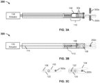
- FIGS. 3A, 3B are diagrams illustrating an embodiment of a side view and a top-down view of an end effector, respectively.
- the end effector 300 is in a closed state.
- end effector 300 is in an open position, for example, as seen in FIGS 2A-2C .
- actuator 118 applies a force to actuation connection structure 114.
- the applied force pulls actuation connection structure 114 towards a proximal end of the end effector.
- the applied force causes the loop portion 108 of actuation connection structure 114 to move from a distal end of the slot openings associated with cutting mechanism 102 and gripping mechanism 104 towards a proximal end of the slot openings associated with cutting mechanism 102 and gripping mechanism 104.
- loop portion 108 has moved a distance 304.
- the loop portion 108 of actuation connection structure 114 transfers the applied force to slot openings associated with cutting mechanism 102 and gripping mechanism 104.
- the loop portion 108 of actuation connection structure 114 is interlocked with the slot openings associated with cutting mechanism 102 and gripping mechanism 104.
- the width of slot openings 122 associated with cutting mechanism 102 may be the width of loop portion 108 of actuation connection structure 114.
- the applied force initially causes gripping mechanism 104 to grip appendage 202. As more force is applied, the applied force causes cutting mechanism 102 to perform a bypass cut of appendage 202, which causes appendage 202 to split into a first portion 302a and a second portion 302b.
- the amount of force with which cutting mechanism 102 applies to appendage 202 is proportional to the force applied by actuator 118.
- bias component 110 When placed in between a proximal end of bias limiting component 112 and a proximal end of loop portion 108, bias component 110 is preloaded with a particular amount of force.
- the preloaded force may be a force that is unable to cut an appendage, regardless of the appendage diameter (e.g., 1 mm - 1 cm).
- bias component 110 may be preloaded with 20 lbs (or 9.07 kg) of force.
- the preloaded amount is within a threshold of the particular amount of force (e.g., ⁇ 5 lbs (or 2.26 kg)).
- bias component 110 When actuator 118 applies a force to actuation connection structure 114, the force causes bias component 110 to compress.
- the amount of force with which gripping mechanism 104 applies to appendage may not exceed the preloaded amount of force within the threshold amount. In the event the amount of force applied by actuator 118 increases, the amount of force applied by gripping mechanism 104 to appendage 302b does not exceed the preloaded amount of force within a threshold amount.
- a robotic arm coupled to end effector 300 may move end effector 300 to a location at which the harvested object is stored.
- Actuator 118 applies a force that causes cutting mechanism 102 and gripping mechanism to open, for example as shown in FIGS 2A, 2B .
- the harvested object attached to the second portion 302 may be placed in a temporary storage location (e.g., bin, tray) associated with a robotic system that includes the robotic arm. As a result, the end effector is able to harvest an object from the plant without damaging the harvested object.
- FIG. 3C is a diagram illustrating an embodiment of a top-down view of a cutting mechanism and a gripping mechanism.
- cutting mechanism 102 and gripping mechanism 104 are both in a closed position.
- Cutting mechanism 102 has split appendage 202 into a first portion 302a and a second portion 302b.
- the first portion 302a may stay attached to the plant after being separated from appendage 202 while the second portion 302b is grasped by gripping mechanism 104.
- the loop portion 108 of actuation connection structure 114 is located at a proximal end of distal end of the slot openings 122.
- the knob feature 120 of bias limiting mechanism 112 has moved from a distal end of slot openings 124 towards a proximal end of slot openings 124, but has not fully moved towards the proximal end of slot openings 124 because gripping mechanism 104 is grasping the second portion 302b of appendage 202.
- the knob feature 120 of bias mechanism completely moves towards the proximal end of slot openings, for example, as seen in FIG. 1C .
Landscapes
- Engineering & Computer Science (AREA)
- Life Sciences & Earth Sciences (AREA)
- Robotics (AREA)
- Environmental Sciences (AREA)
- Mechanical Engineering (AREA)
- Forests & Forestry (AREA)
- Biodiversity & Conservation Biology (AREA)
- Ecology (AREA)
- Harvesting Machines For Specific Crops (AREA)
- Manipulator (AREA)
Claims (17)
- Endeffektor (100; 200; 300), der Folgendes umfasst:einen Schneidmechanismus (102), der einen Satz Schneidbacken aufweist,einen Greifmechanismus (104), der einen Satz Greifbacken aufweist,eine Gelenkkomponente (106), wobei der Schneidmechanismus und der Greifmechanismus mit der Gelenkkomponente gekoppelt sind, wobei der Schneidmechanismus mit einem ersten Abschnitt der Gelenkkomponente und der Greifmechanismus mit einem zweiten Abschnitt der Gelenkkomponente gekoppelt ist, undeine Betätigungsverbindungskonstruktion (114), wobei die Betätigungsverbindungskonstruktion einen geraden Abschnitt (113) und einen Schlaufenabschnitt (108) aufweist, wobei der Schlaufenabschnitt der Betätigungsverbindungskonstruktion über zum Schneidmechanismus gehörende Schlitzöffnungen (122) mit dem Schneidmechanismus und über zum Greifmechanismus gehörende Schlitzöffnungen (124) mit dem Greifmechanismus gekoppelt ist, wobei eine Breite der zum Schneidmechanismus gehörenden Schlitzöffnungen geringer ist als eine Breite der zum Greifmechanismus gehörenden Schlitzöffnungen.
- Endeffektor (100; 200; 300) nach Anspruch 1, wobei es sich bei dem ersten Abschnitt um einen oberen Abschnitt der Gelenkkomponente (106) und bei dem zweiten Abschnitt um einen unteren Abschnitt der Gelenkkomponente handelt.
- Endeffektor (100; 200; 300) nach Anspruch 1, wobei es sich bei dem ersten Abschnitt um einen unteren Abschnitt der Gelenkkomponente (106) und bei dem zweiten Abschnitt um einen oberen Abschnitt der Gelenkkomponente handelt.
- Endeffektor (100; 200; 300) nach einem der vorhergehenden Ansprüche, der ferner einen Vorspannmechanismus (110) umfasst, wobei der Vorspannmechanismus mit dem Greifmechanismus (104) gekoppelt ist.
- Endeffektor (100; 200; 300) nach Anspruch 4, wobei der Vorspannmechanismus (110) so ausgelegt ist, dass er eine Kraft auf den Greifmechanismus (104) ausübt, die innerhalb eines Grenzwerts liegt.
- Endeffektor (100; 200; 300) nach Anspruch 4 oder 5, wobei es sich bei dem Vorspannmechanismus (110) um eine Feder handelt.
- Endeffektor (100; 200; 300) nach einem der Ansprüche 4 bis 6, wobei der Vorspannmechanismus (110) mit einer bestimmten Kraft vorgespannt ist.
- Endeffektor (100; 200; 300) nach einem der Ansprüche 4 bis 7, wobei der Vorspannmechanismus (110) mit einer Vorspannungsbegrenzungskomponente (112) gekoppelt ist.
- Endeffektor (100; 200; 300) nach Anspruch 8, wobei die Vorspannungsbegrenzungskomponente (112) einen Nutabschnitt (115) aufweist.
- Endeffektor (100; 200; 300) nach einem der Ansprüche 1, wobei die Betätigungsverbindungskonstruktion (114) mit einem Aktor (118) gekoppelt ist.
- Endeffektor (100; 200; 300) nach Anspruch 10, wobei die Betätigungsverbindungskonstruktion (114) so ausgelegt ist, dass sie als Reaktion auf eine von dem Aktor (118) ausgeübte Kraft den Schneidmechanismus (102) und den Greifmechanismus (104) öffnet.
- Endeffektor (100; 200; 300) nach Anspruch 11, wobei der Aktor (118) so ausgelegt ist, dass er die Betätigungsverbindungskonstruktion (114) zu einem distalen Ende des Endeffektors hin schiebt.
- Endeffektor (100; 200; 300) nach Anspruch 10, wobei die Betätigungsverbindungskonstruktion (114) so ausgelegt ist, dass sie als Reaktion auf eine von dem Aktor (118) ausgeübte Kraft den Schneidmechanismus (102) und den Greifmechanismus (104) schließt.
- Endeffektor (100; 200; 300) nach Anspruch 13, wobei der Aktor (118) so ausgelegt ist, dass er die Betätigungsverbindungskonstruktion (114) zu einem proximalen Ende des Endeffektors hin zieht.
- Endeffektor (100; 200; 300) nach einem der Ansprüche 10 bis 14, der ferner ein Gehäuse (116) umfasst, wobei sich die Betätigungsverbindungskonstruktion (114), ein proximales Ende des Schneidmechanismus (102) und ein proximales Ende des Greifmechanismus (104) in dem Gehäuse befinden.
- Endeffektor (100; 200; 300) nach einem der Ansprüche 10 bis 15, wobei die Betätigungsverbindungskonstruktion (114) so ausgelegt ist, dass sie als Reaktion auf eine von dem Aktor (118) ausgeübte Kraft bewirkt, dass der Greifmechanismus (104) einen Fortsatz (202) einer Pflanze ergreift.
- Endeffektor (100; 200; 300) nach Anspruch 16, wobei die Betätigungsverbindungskonstruktion (114) so ausgelegt ist, dass sie als Reaktion auf die von dem Aktor (118) ausgeübte Kraft bewirkt, dass der Schneidmechanismus (102) einen Schnitt an dem Fortsatz (202) durchführt, wobei der Fortsatz in einen ersten Abschnitt (302a) und einen zweiten Abschnitt (302b) zerteilt wird, wobei der Greifmechanismus (104) so ausgelegt ist, dass er den zweiten Abschnitt ergreift.
Applications Claiming Priority (1)
| Application Number | Priority Date | Filing Date | Title |
|---|---|---|---|
| US17/168,019 US11406060B1 (en) | 2021-02-04 | 2021-02-04 | End effector for harvesting |
Publications (2)
| Publication Number | Publication Date |
|---|---|
| EP4039079A1 EP4039079A1 (de) | 2022-08-10 |
| EP4039079B1 true EP4039079B1 (de) | 2025-05-28 |
Family
ID=74947015
Family Applications (1)
| Application Number | Title | Priority Date | Filing Date |
|---|---|---|---|
| EP21162946.4A Active EP4039079B1 (de) | 2021-02-04 | 2021-03-16 | Endeffektor für die ernte |
Country Status (4)
| Country | Link |
|---|---|
| US (4) | US11406060B1 (de) |
| EP (1) | EP4039079B1 (de) |
| JP (1) | JP7576182B2 (de) |
| WO (1) | WO2022169883A1 (de) |
Families Citing this family (3)
| Publication number | Priority date | Publication date | Assignee | Title |
|---|---|---|---|---|
| EP3838489B1 (de) * | 2019-12-19 | 2022-05-04 | Stanley Black & Decker MEA FZE | Ergonomische zange |
| CN115886895A (zh) * | 2022-11-29 | 2023-04-04 | 山东威高手术机器人有限公司 | 一种末端执行器可拆卸的多自由度微创手术器械 |
| WO2025234258A1 (ja) * | 2024-05-08 | 2025-11-13 | 株式会社デンソー | 農作物収穫用エンドエフェクタ |
Family Cites Families (47)
| Publication number | Priority date | Publication date | Assignee | Title |
|---|---|---|---|---|
| US608807A (en) * | 1898-08-09 | The nor | ||
| US681972A (en) * | 1901-05-24 | 1901-09-03 | Isaac Postlethwait | Scissors. |
| US778140A (en) * | 1904-06-08 | 1904-12-20 | Charles Paff | Stem holding and cutting shears. |
| US1493539A (en) * | 1921-09-22 | 1924-05-13 | Thomas A Murray | Picking shears |
| US1467262A (en) * | 1922-05-16 | 1923-09-04 | Barker Philip | Pneumatically-operated cutting tool |
| US2028239A (en) * | 1932-02-17 | 1936-01-21 | Peter J Oths | Corer for grapefruit, etc. |
| US2366609A (en) * | 1942-02-21 | 1945-01-02 | Sylvania Electric Prod | Lamp flare machine |
| US2366909A (en) * | 1943-06-29 | 1945-01-09 | Charles J Johnson | Power actuated pruning shears |
| US2446011A (en) * | 1945-08-06 | 1948-07-27 | Charles J Johnson | Hydraulic motor with pistol grip handle and trigger actuated valve |
| US2493696A (en) * | 1945-12-29 | 1950-01-03 | Potstada Magdalena | Air operated shears |
| US2540255A (en) | 1947-05-09 | 1951-02-06 | Graves Donald | Fruit clipper |
| US2930122A (en) * | 1957-06-27 | 1960-03-29 | George M Pfundt | Hydraulic tree pruner |
| US3039189A (en) * | 1961-08-24 | 1962-06-19 | Robert K Mcberty | Hydraulically operated pruning tool |
| US3584381A (en) * | 1968-01-29 | 1971-06-15 | Joe M Jamison | Tree trimming and pruning device |
| US3685151A (en) * | 1970-07-23 | 1972-08-22 | Dynamic Tools Ltd | Hydraulically operated hand tools |
| US3693254A (en) * | 1970-08-26 | 1972-09-26 | Albert R Salonen | Motorized shearing implement |
| JPS56111729U (de) * | 1980-01-29 | 1981-08-28 | ||
| JPS59107886A (ja) * | 1982-12-08 | 1984-06-22 | 株式会社クボタ | 果実収穫用ロボツトハンド |
| JPH0726915Y2 (ja) * | 1990-10-25 | 1995-06-21 | アルスコーポレーション株式会社 | 摘果用カッター |
| FR2677908B1 (fr) * | 1991-06-20 | 1995-04-07 | Hydr Am | Outil autonome polyvalent tel que cisaille/ecarteur a commande hydraulique. |
| US5189794A (en) * | 1991-12-16 | 1993-03-02 | Young-Life International Co., Ltd. | Pair of shears with tongs |
| AT403491B (de) * | 1996-02-15 | 1998-02-25 | Wimmer Alois Ing | Betonbrechzange mit schneidschere |
| US5695521A (en) * | 1996-10-01 | 1997-12-09 | Symbiosis Corporation | Tubular sheath protective insert |
| US5826341A (en) * | 1997-07-10 | 1998-10-27 | Massa; Robert E. | Tree trimmer |
| US6530099B1 (en) * | 2000-07-19 | 2003-03-11 | Snap-On Technologies, Inc. | Injection molded pliers with insert molded dual purpose reinforcing and implement structure |
| JP2006061162A (ja) | 2000-12-04 | 2006-03-09 | Kobelco Contstruction Machinery Ltd | 作業機械 |
| US6877230B2 (en) * | 2002-02-22 | 2005-04-12 | Chris Tapia | Method and apparatus for cutting hair |
| JP3757279B2 (ja) | 2002-12-02 | 2006-03-22 | 独立行政法人農業・生物系特定産業技術研究機構 | 果菜類の選択収穫方法及び装置 |
| US20040134074A1 (en) * | 2003-01-10 | 2004-07-15 | Chi-Sui Lin | Gardening flower scissors with container |
| JP2005176745A (ja) | 2003-12-19 | 2005-07-07 | Satoshi Iwase | 果実採取作業具 |
| US8568442B2 (en) * | 2005-06-14 | 2013-10-29 | Karl Storz Gmbh & Co. Kg | Medical gripping and/or cutting instrument |
| US7331109B2 (en) * | 2006-05-12 | 2008-02-19 | Shu-Woan Tu | Electric cutting device |
| US7540093B1 (en) * | 2006-09-20 | 2009-06-02 | Chung Cheng Scissors Co. | Gardening shears |
| US7658011B2 (en) * | 2007-08-07 | 2010-02-09 | Natura Innovation Ltd. | Lopper |
| JP5332662B2 (ja) * | 2009-01-30 | 2013-11-06 | マックス株式会社 | 電動はさみ |
| US8209871B1 (en) * | 2009-02-05 | 2012-07-03 | Palmby Chris D | Cutting apparatus |
| US9456839B2 (en) * | 2010-06-18 | 2016-10-04 | Intuitive Surgical Operations, Inc. | Scissor bias for direct pull surgical instrument |
| CO6360206A1 (es) * | 2010-07-30 | 2012-01-20 | Pontifica Universidad Javerian | Herramienta ergonomica para el corte de flores y frutos |
| CA2810435C (en) * | 2010-09-14 | 2017-03-21 | National Oilwell Varco, L.P. | Blowout preventer ram assembly and method of using same |
| KR200474257Y1 (ko) | 2014-02-13 | 2014-09-04 | 권익삼 | 속과기 |
| JP5797350B1 (ja) | 2015-04-01 | 2015-10-21 | 株式会社Atta | 作物収穫用工具 |
| US20170000027A1 (en) | 2015-07-02 | 2017-01-05 | Terence D. Hunt | Robotic harvester |
| CN106233938B (zh) | 2016-09-22 | 2018-06-26 | 佛山科学技术学院 | 串型水果采摘机器人的末端执行器 |
| JP6939262B2 (ja) | 2017-08-29 | 2021-09-22 | 株式会社デンソー | エンドエフェクタ |
| SE1850296A1 (en) | 2018-03-16 | 2019-09-17 | Strihl Scandinavia Ab | A method and a system for replacing existing lighting luminaire with replacement lighting luminaire |
| KR101999636B1 (ko) | 2019-01-31 | 2019-07-12 | 박재언 | 엔드이펙터 |
| CN111958624B (zh) | 2020-08-27 | 2022-11-15 | 上海大学 | 一种多连杆结构的柑橘采摘末端执行器 |
-
2021
- 2021-02-04 US US17/168,019 patent/US11406060B1/en active Active
- 2021-03-16 EP EP21162946.4A patent/EP4039079B1/de active Active
-
2022
- 2022-02-02 JP JP2023547260A patent/JP7576182B2/ja active Active
- 2022-02-02 WO PCT/US2022/014955 patent/WO2022169883A1/en not_active Ceased
- 2022-06-23 US US17/847,912 patent/US11716934B2/en active Active
-
2023
- 2023-06-19 US US18/211,505 patent/US12178160B2/en active Active
-
2024
- 2024-11-20 US US18/954,039 patent/US20250185543A1/en active Pending
Also Published As
| Publication number | Publication date |
|---|---|
| WO2022169883A1 (en) | 2022-08-11 |
| EP4039079A1 (de) | 2022-08-10 |
| US20250185543A1 (en) | 2025-06-12 |
| US11716934B2 (en) | 2023-08-08 |
| US20220240448A1 (en) | 2022-08-04 |
| US12178160B2 (en) | 2024-12-31 |
| US20220386532A1 (en) | 2022-12-08 |
| US20230329149A1 (en) | 2023-10-19 |
| US11406060B1 (en) | 2022-08-09 |
| JP7576182B2 (ja) | 2024-10-30 |
| JP2024505994A (ja) | 2024-02-08 |
Similar Documents
| Publication | Publication Date | Title |
|---|---|---|
| US12178160B2 (en) | End effector for harvesting | |
| US8931527B2 (en) | Tree processing head | |
| CN112136539B (zh) | 一种果蔬整枝打叶执行器及整枝机器人 | |
| JP7234915B2 (ja) | エンドエフェクタ | |
| US20210283788A1 (en) | Device and method for fruit harvesting | |
| EP0810818A1 (de) | Verfahren und geräte zum ernten von landwirtschaftlichen produkten | |
| US3720246A (en) | Method and apparatus for handling trees | |
| KR102511629B1 (ko) | 농작물 작업장치용 엔드 이펙터 | |
| EP4373255B1 (de) | Landwirtschaftlicher manipulator; anordnung davon mit einem roboterarm | |
| Guo | Review of current mechanical design in agricultural end effector | |
| Jia et al. | Integrated gripper and cutter in a mobile robotic system for harvesting greenhouse products | |
| CA3187386A1 (en) | Tool, device and procedure for the automated separation of a branch | |
| KR102831759B1 (ko) | 과실 자동 적과 장치 및 과실 적과 장치를 구비하는 적과 로봇 | |
| KR20160126546A (ko) | 농업용 가위 | |
| US5142854A (en) | Fruit harvesting device | |
| CN215774415U (zh) | 一种果树修剪装置 | |
| KR102938985B1 (ko) | 작물 수확용 절단장치 | |
| AU3585299A (en) | Cutting apparatus | |
| JP2025140636A (ja) | 農作物収穫用エンドエフェクタ、及び農作物収穫システム | |
| CN222148289U (zh) | 一种采摘机器人用剪切机构 | |
| Bauer et al. | Soft robotic end‐effectors in the wild: A case study of a soft manipulator for green bell pepper harvesting | |
| WO2025027171A1 (en) | Harvesting cutting and gripper head | |
| WO2025234258A1 (ja) | 農作物収穫用エンドエフェクタ | |
| JP2024175940A (ja) | 摘み取り装置 | |
| NL1017531C2 (nl) | Inrichting en werkwijze voor het oogsten van een gewasstengel. |
Legal Events
| Date | Code | Title | Description |
|---|---|---|---|
| PUAI | Public reference made under article 153(3) epc to a published international application that has entered the european phase |
Free format text: ORIGINAL CODE: 0009012 |
|
| STAA | Information on the status of an ep patent application or granted ep patent |
Free format text: STATUS: THE APPLICATION HAS BEEN PUBLISHED |
|
| AK | Designated contracting states |
Kind code of ref document: A1 Designated state(s): AL AT BE BG CH CY CZ DE DK EE ES FI FR GB GR HR HU IE IS IT LI LT LU LV MC MK MT NL NO PL PT RO RS SE SI SK SM TR |
|
| STAA | Information on the status of an ep patent application or granted ep patent |
Free format text: STATUS: REQUEST FOR EXAMINATION WAS MADE |
|
| 17P | Request for examination filed |
Effective date: 20221121 |
|
| RBV | Designated contracting states (corrected) |
Designated state(s): AL AT BE BG CH CY CZ DE DK EE ES FI FR GB GR HR HU IE IS IT LI LT LU LV MC MK MT NL NO PL PT RO RS SE SI SK SM TR |
|
| P01 | Opt-out of the competence of the unified patent court (upc) registered |
Effective date: 20230605 |
|
| GRAP | Despatch of communication of intention to grant a patent |
Free format text: ORIGINAL CODE: EPIDOSNIGR1 |
|
| STAA | Information on the status of an ep patent application or granted ep patent |
Free format text: STATUS: GRANT OF PATENT IS INTENDED |
|
| RIC1 | Information provided on ipc code assigned before grant |
Ipc: A01D 46/28 20060101ALN20241205BHEP Ipc: A01G 3/02 20060101ALI20241205BHEP Ipc: B25J 15/00 20060101ALI20241205BHEP Ipc: A01D 46/30 20060101AFI20241205BHEP |
|
| INTG | Intention to grant announced |
Effective date: 20241216 |
|
| GRAS | Grant fee paid |
Free format text: ORIGINAL CODE: EPIDOSNIGR3 |
|
| GRAA | (expected) grant |
Free format text: ORIGINAL CODE: 0009210 |
|
| STAA | Information on the status of an ep patent application or granted ep patent |
Free format text: STATUS: THE PATENT HAS BEEN GRANTED |
|
| RAP1 | Party data changed (applicant data changed or rights of an application transferred) |
Owner name: OISHII FARM CORPORATION |
|
| AK | Designated contracting states |
Kind code of ref document: B1 Designated state(s): AL AT BE BG CH CY CZ DE DK EE ES FI FR GB GR HR HU IE IS IT LI LT LU LV MC MK MT NL NO PL PT RO RS SE SI SK SM TR |
|
| REG | Reference to a national code |
Ref country code: GB Ref legal event code: FG4D |
|
| REG | Reference to a national code |
Ref country code: CH Ref legal event code: EP |
|
| REG | Reference to a national code |
Ref country code: IE Ref legal event code: FG4D Ref country code: DE Ref legal event code: R096 Ref document number: 602021031338 Country of ref document: DE |
|
| REG | Reference to a national code |
Ref country code: NL Ref legal event code: FP |
|
| PG25 | Lapsed in a contracting state [announced via postgrant information from national office to epo] |
Ref country code: ES Free format text: LAPSE BECAUSE OF FAILURE TO SUBMIT A TRANSLATION OF THE DESCRIPTION OR TO PAY THE FEE WITHIN THE PRESCRIBED TIME-LIMIT Effective date: 20250528 Ref country code: FI Free format text: LAPSE BECAUSE OF FAILURE TO SUBMIT A TRANSLATION OF THE DESCRIPTION OR TO PAY THE FEE WITHIN THE PRESCRIBED TIME-LIMIT Effective date: 20250528 |
|
| REG | Reference to a national code |
Ref country code: LT Ref legal event code: MG9D |
|
| PG25 | Lapsed in a contracting state [announced via postgrant information from national office to epo] |
Ref country code: NO Free format text: LAPSE BECAUSE OF FAILURE TO SUBMIT A TRANSLATION OF THE DESCRIPTION OR TO PAY THE FEE WITHIN THE PRESCRIBED TIME-LIMIT Effective date: 20250828 Ref country code: GR Free format text: LAPSE BECAUSE OF FAILURE TO SUBMIT A TRANSLATION OF THE DESCRIPTION OR TO PAY THE FEE WITHIN THE PRESCRIBED TIME-LIMIT Effective date: 20250829 |
|
| PG25 | Lapsed in a contracting state [announced via postgrant information from national office to epo] |
Ref country code: PL Free format text: LAPSE BECAUSE OF FAILURE TO SUBMIT A TRANSLATION OF THE DESCRIPTION OR TO PAY THE FEE WITHIN THE PRESCRIBED TIME-LIMIT Effective date: 20250528 |
|
| PG25 | Lapsed in a contracting state [announced via postgrant information from national office to epo] |
Ref country code: BG Free format text: LAPSE BECAUSE OF FAILURE TO SUBMIT A TRANSLATION OF THE DESCRIPTION OR TO PAY THE FEE WITHIN THE PRESCRIBED TIME-LIMIT Effective date: 20250528 |
|
| PG25 | Lapsed in a contracting state [announced via postgrant information from national office to epo] |
Ref country code: HR Free format text: LAPSE BECAUSE OF FAILURE TO SUBMIT A TRANSLATION OF THE DESCRIPTION OR TO PAY THE FEE WITHIN THE PRESCRIBED TIME-LIMIT Effective date: 20250528 |
|
| PG25 | Lapsed in a contracting state [announced via postgrant information from national office to epo] |
Ref country code: RS Free format text: LAPSE BECAUSE OF FAILURE TO SUBMIT A TRANSLATION OF THE DESCRIPTION OR TO PAY THE FEE WITHIN THE PRESCRIBED TIME-LIMIT Effective date: 20250828 |
|
| PG25 | Lapsed in a contracting state [announced via postgrant information from national office to epo] |
Ref country code: IS Free format text: LAPSE BECAUSE OF FAILURE TO SUBMIT A TRANSLATION OF THE DESCRIPTION OR TO PAY THE FEE WITHIN THE PRESCRIBED TIME-LIMIT Effective date: 20250928 |
|
| PG25 | Lapsed in a contracting state [announced via postgrant information from national office to epo] |
Ref country code: LV Free format text: LAPSE BECAUSE OF FAILURE TO SUBMIT A TRANSLATION OF THE DESCRIPTION OR TO PAY THE FEE WITHIN THE PRESCRIBED TIME-LIMIT Effective date: 20250528 |
|
| REG | Reference to a national code |
Ref country code: AT Ref legal event code: MK05 Ref document number: 1798077 Country of ref document: AT Kind code of ref document: T Effective date: 20250528 |
|
| PG25 | Lapsed in a contracting state [announced via postgrant information from national office to epo] |
Ref country code: SM Free format text: LAPSE BECAUSE OF FAILURE TO SUBMIT A TRANSLATION OF THE DESCRIPTION OR TO PAY THE FEE WITHIN THE PRESCRIBED TIME-LIMIT Effective date: 20250528 Ref country code: DK Free format text: LAPSE BECAUSE OF FAILURE TO SUBMIT A TRANSLATION OF THE DESCRIPTION OR TO PAY THE FEE WITHIN THE PRESCRIBED TIME-LIMIT Effective date: 20250528 Ref country code: AT Free format text: LAPSE BECAUSE OF FAILURE TO SUBMIT A TRANSLATION OF THE DESCRIPTION OR TO PAY THE FEE WITHIN THE PRESCRIBED TIME-LIMIT Effective date: 20250528 |
|
| PG25 | Lapsed in a contracting state [announced via postgrant information from national office to epo] |
Ref country code: CZ Free format text: LAPSE BECAUSE OF FAILURE TO SUBMIT A TRANSLATION OF THE DESCRIPTION OR TO PAY THE FEE WITHIN THE PRESCRIBED TIME-LIMIT Effective date: 20250528 |
|
| PG25 | Lapsed in a contracting state [announced via postgrant information from national office to epo] |
Ref country code: EE Free format text: LAPSE BECAUSE OF FAILURE TO SUBMIT A TRANSLATION OF THE DESCRIPTION OR TO PAY THE FEE WITHIN THE PRESCRIBED TIME-LIMIT Effective date: 20250528 |
|
| PG25 | Lapsed in a contracting state [announced via postgrant information from national office to epo] |
Ref country code: SK Free format text: LAPSE BECAUSE OF FAILURE TO SUBMIT A TRANSLATION OF THE DESCRIPTION OR TO PAY THE FEE WITHIN THE PRESCRIBED TIME-LIMIT Effective date: 20250528 |
|
| PG25 | Lapsed in a contracting state [announced via postgrant information from national office to epo] |
Ref country code: IT Free format text: LAPSE BECAUSE OF FAILURE TO SUBMIT A TRANSLATION OF THE DESCRIPTION OR TO PAY THE FEE WITHIN THE PRESCRIBED TIME-LIMIT Effective date: 20250528 |
|
| REG | Reference to a national code |
Ref country code: DE Ref legal event code: R097 Ref document number: 602021031338 Country of ref document: DE |
|
| PLBE | No opposition filed within time limit |
Free format text: ORIGINAL CODE: 0009261 |
|
| STAA | Information on the status of an ep patent application or granted ep patent |
Free format text: STATUS: NO OPPOSITION FILED WITHIN TIME LIMIT |
|
| PGFP | Annual fee paid to national office [announced via postgrant information from national office to epo] |
Ref country code: GB Payment date: 20260318 Year of fee payment: 6 |
|
| REG | Reference to a national code |
Ref country code: CH Ref legal event code: L10 Free format text: ST27 STATUS EVENT CODE: U-0-0-L10-L00 (AS PROVIDED BY THE NATIONAL OFFICE) Effective date: 20260409 |
|
| PGFP | Annual fee paid to national office [announced via postgrant information from national office to epo] |
Ref country code: DE Payment date: 20260327 Year of fee payment: 6 |
|
| PGFP | Annual fee paid to national office [announced via postgrant information from national office to epo] |
Ref country code: NL Payment date: 20260319 Year of fee payment: 6 |
|
| 26N | No opposition filed |
Effective date: 20260303 |
|
| PG25 | Lapsed in a contracting state [announced via postgrant information from national office to epo] |
Ref country code: LT Free format text: LAPSE BECAUSE OF FAILURE TO SUBMIT A TRANSLATION OF THE DESCRIPTION OR TO PAY THE FEE WITHIN THE PRESCRIBED TIME-LIMIT Effective date: 20250528 |
|
| PG25 | Lapsed in a contracting state [announced via postgrant information from national office to epo] |
Ref country code: SE Free format text: LAPSE BECAUSE OF FAILURE TO SUBMIT A TRANSLATION OF THE DESCRIPTION OR TO PAY THE FEE WITHIN THE PRESCRIBED TIME-LIMIT Effective date: 20250528 |