EP4035911B1 - Brücke für einen übergang zwischen zwei gelenkig miteinander verbundenen fahrzeugteilen - Google Patents
Brücke für einen übergang zwischen zwei gelenkig miteinander verbundenen fahrzeugteilen Download PDFInfo
- Publication number
- EP4035911B1 EP4035911B1 EP21154115.6A EP21154115A EP4035911B1 EP 4035911 B1 EP4035911 B1 EP 4035911B1 EP 21154115 A EP21154115 A EP 21154115A EP 4035911 B1 EP4035911 B1 EP 4035911B1
- Authority
- EP
- European Patent Office
- Prior art keywords
- bridge
- tread plate
- coupling element
- vehicle parts
- base plates
- Prior art date
- Legal status (The legal status is an assumption and is not a legal conclusion. Google has not performed a legal analysis and makes no representation as to the accuracy of the status listed.)
- Active
Links
Images
Classifications
-
- B—PERFORMING OPERATIONS; TRANSPORTING
- B61—RAILWAYS
- B61D—BODY DETAILS OR KINDS OF RAILWAY VEHICLES
- B61D17/00—Construction details of vehicle bodies
- B61D17/04—Construction details of vehicle bodies with bodies of metal; with composite, e.g. metal and wood body structures
- B61D17/20—Communication passages between coaches; Adaptation of coach ends therefor
-
- B—PERFORMING OPERATIONS; TRANSPORTING
- B60—VEHICLES IN GENERAL
- B60D—VEHICLE CONNECTIONS
- B60D5/00—Gangways for coupled vehicles, e.g. of concertina type
- B60D5/006—Passages between articulated vehicles, e.g. bridges or rotating plates
Definitions
- the present invention relates to a bridge for a transition between two articulated vehicle parts, in particular a rail vehicle, wherein the bridge extends in a passage direction and a width direction normal thereto, the bridge comprising two floor panels, each of which is provided for articulated arrangement on an end face of the vehicle parts and has a floor panel upper side that can be walked on at least in sections, wherein at least one coupling element, preferably two coupling elements, is/are provided in front of the floor panels in a height direction, wherein the height direction is normal to the passage direction and the width direction and points away from the floor panel upper sides.
- Bridges for transitions between two articulated vehicle parts, in particular a rail vehicle, are known per se.
- these bridges comprise two walkable floor plates that are articulatedly mounted on the front sides of the vehicle parts in order to to take into account the height offset between the vehicle parts that occurs during driving.
- EP2457796B1 It is known to provide means for pressing the floor plates against the tread plate on a centering member connected to the tread plate and the front sides of the vehicle parts in order to prevent the formation of a gap between the tread plate and the floor plates during pitching, rolling and buckling movements or superimposed movements of the vehicle parts relative to one another.
- the object of the present invention is to provide a bridge in which the floor plates can be ideally deflected in a structurally simple and cost-effective manner in order to be able to reliably follow all movements of the vehicle parts relative to one another that typically occur during driving. Furthermore, the solution according to the invention is intended regardless of whether a step plate is provided or not.
- the direction of passage could also be called the first direction, the width direction the second direction and the height direction the third direction, where the first direction, the second direction and the third direction are mutually perpendicular to each other.
- the bridge can be walked on by a user parallel to the direction of passage, whereby "parallel” here and in the following also includes the opposite direction (i.e. the bridge can also be walked on against the direction of passage), unless explicitly stated otherwise.
- the bridge can be designed with or without a tread plate. If no tread plate is provided, the walkway is typically essentially exclusively over the tops of the floor panels, although these do not necessarily have to be completely accessible, as the floor panels can overlap in sections. If a step panel is provided, access typically takes place over both the tops of the floor panels and the top of a step panel, whereby both the tops of the floor panels and the top of the step panel can then be accessible at least in sections, and whereby the step panel and floor panels can overlap in sections and vice versa.
- the articulated arrangement of the floor panels on the front sides of the vehicle parts can be carried out in a conventional manner, for example by means of hinges.
- the floor panels especially the top surfaces of the floor panels, can be constructed in one or more parts.
- the base plates can be made of metal, for example, comprising in particular one or more aluminum alloys.
- the at least one coupling element or the coupling elements can be designed in a variety of ways in a manner known per se.
- scissor gates and/or rack and pinion gears can be used as coupling elements.
- the at least one coupling element can be made of metal, for example, comprising in particular one or more aluminum alloys.
- two coupling elements are preferably provided, although more than two coupling elements (i.e. three, four, etc.) can also be provided. In particular, if two coupling elements are provided, these can be arranged on both sides of the bridge, as seen in the direction of passage.
- the rotationally movable connections of the at least one coupling element with the two base plates do not exclude the possibility that further movements are permitted through the connections.
- the connections can be designed in such a way that linear movements, in particular with a directional component parallel to the vertical direction, are permitted at least in a certain area.
- rotational mobility about an axis of rotation parallel to the vertical direction and at the same time linear mobility (in a certain area) parallel to the vertical direction can be realized by means of a radial bearing with two degrees of freedom.
- Such radial bearings which allow rotation about an axis of rotation and translation along the axis of rotation, are known per se.
- radial bearings always mean radial bearings with two degrees of freedom, unless explicitly stated otherwise.
- the coupling elements that connect the two floor plates together ensure that the floor plates are optimally deflected when the vehicle parts move relative to one another during driving, whereby the relative movements can in particular include an offset parallel to the vertical direction.
- the optimal deflection of the floor plates in turn guarantees that the bridge can be walked on without any problems even when the vehicle parts move relative to one another as mentioned.
- connection/connection is understood to mean only one that has a significant mechanical load-bearing capacity with loads such as those that typically occur during operation of the transition.
- the axis of rotation of the rotatable connection between the coupling element and the base plates can in principle be chosen arbitrarily.
- the rotational mobility is not necessarily limited to just one axis of rotation, but can include several or even an infinite number of axes of rotation.
- at least one spherical bearing is provided for the rotatable connection of the at least one coupling element to at least one of the base plates. In the mathematical sense, this enables rotations about an infinite number of axes of rotation, which ensures optimal mobility between the at least one coupling element and the base plates and thus optimal deflection of the base plates, particularly in the case of relative movements of the vehicle parts to one another that run transversely to the height direction.
- the coupling element or coupling elements are only connected to one of the base plates via a spherical bearing in order to ensure sufficient mobility between the connected elements and thus optimal deflection of the base plates.
- the connection to the other base plate can then be made, for example, via a simple rotary bearing (with exactly one degree of freedom, namely rotation about exactly one axis of rotation) or a radial bearing. In addition to cost advantages, this can also result in advantages in terms of the stability of the resulting arrangement of the base plates.
- the at least one coupling element, preferably the coupling elements is/are connected to both base plates via spherical bearings, thus ensuring maximum mobility between the connected elements.
- the at least one coupling element has at least one sliding body, preferably made of plastic, on which sliding body at least one of the base plate undersides rests in a sliding manner.
- This enables the respective base plate to be supported by the at least one coupling element, which increases stability when walking on the bridge.
- it also enables the respective base plate to slide easily relative to at least one section of the at least one coupling element, in particular when there are relative movements of the vehicle parts to one another, preferably parallel to the height direction.
- Plastics with suitable sliding properties are known per se, for example polytetrafluoroethylene.
- the bridge according to the invention can be designed with or without a step plate.
- a step plate can prove to be advantageous.
- the bridge comprises a step plate with a step plate upper side that can be walked on at least in sections, wherein the step plate is arranged at least in sections between the base plates parallel to the height direction, wherein the at least one coupling element for centering the step plate is rotatably connected to the step plate on a step plate lower side opposite the step plate upper side.
- the above-mentioned arrangement of the tread plate relative to the floor plates - when viewed in the vertical direction, at least one section of one floor plate, at least one section of the tread plate and at least one section of the other floor plate are visible next to one another - can be implemented in different ways:
- the tread plate can be arranged "above” the floor plates, i.e. viewed in the vertical direction, the tread plate is arranged behind the floor plates;
- the tread plate can be arranged "under” the floor plates, i.e. viewed in the vertical direction, the tread plate is arranged in front of the floor plates;
- the tread plate can be arranged behind one of the two floor plates and in front of the other of the two floor plates, viewed in the vertical direction.
- the at least one coupling element also functions as a centering element for the tread plate.
- the rotatable connection of the at least one coupling element with the step plate makes it possible in particular to compensate for a lateral offset of the vehicle parts to one another (ie in a plane normal to the height direction or parallel to the passage direction and/or the width direction).
- the centering of the step plate in turn guarantees problem-free access the bridge over the step plate even with the aforementioned relative movements or displacements of the vehicle parts to each other. In particular, this can prevent gaps between the floor plates and the step plate.
- the rotational mobility mentioned can be achieved, for example, by means of a pivot bearing that allows rotation around a single axis of rotation, or by means of a radial bearing.
- This single axis of rotation can, for example, be positioned normally on the underside of the tread plate.
- the tread plate is arranged in front of the floor plates in the vertical direction, with the floor plates resting on the top of the tread plate, in particular in a sliding manner.
- the tread plate is arranged under the floor plates.
- the bottom of the floor plate and/or the top of the tread plate can each have their own support section, which, for example by being made from a suitable material or by a suitable coating (e.g. from polytetrafluoroethylene), ensures that the floor plates slide smoothly on the tread plate.
- the tread plate is arranged behind the floor plates in the vertical direction, wherein the tread plate rests on the upper sides of the floor plates, in particular in a sliding manner.
- the tread plate is arranged above the floor plates.
- the upper sides of the floor plates and/or the lower sides of the tread plate can be each have their own support section which, for example by being made from a suitable material or by a suitable coating (e.g. polytetrafluoroethylene), ensures that the tread plate slides smoothly on the floor panels.
- the at least one coupling element has at least one sliding body, preferably made of plastic, on which sliding body the underside of the tread plate rests in a sliding manner.
- This enables the tread plate to be supported by the at least one coupling element, which increases stability when walking on the bridge.
- it also enables the tread plate to slide easily relative to at least one section of the at least one coupling element, in particular when there are relative movements, preferably lateral movements, of the vehicle parts to one another.
- Plastics with suitable sliding properties are known per se, for example polytetrafluoroethylene.
- the at least one coupling element can be designed in a variety of ways.
- the at least one coupling element is designed by at least one scissor grid.
- the scissor grid can be designed as a single scissor or multiple scissors.
- the scissor grid can be used to achieve a secure connection of the floor panels, particularly in the case of - even relatively large - movements of the floor panels relative to one another, which have both directional components parallel to the passage direction and directional components parallel to the width direction.
- one or more of the coupling elements or all of the coupling elements are designed as scissor gates.
- the invention provides a system comprising a first vehicle part and a second vehicle part, wherein the two vehicle parts are connected to one another in an articulated manner and a transition with a bridge according to the invention is provided between the vehicle parts, wherein the at least one coupling element is only indirectly connected to the vehicle parts, in particular via the floor plates.
- the first vehicle part and the second vehicle part can be vehicle parts of a rail vehicle.
- hinges are provided for the articulated arrangement of the floor panels on the front sides of the vehicle parts. This ensures a simple, cost-effective and stable connection so that the floor panels can be pivoted upwards and/or downwards relative to the respective vehicle part. Pivoting takes place around hinge axes which, if the vehicle parts are not offset from one another, preferably run parallel to the width direction.
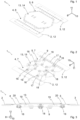
- Fig.1 shows in an axonometric view from above a first embodiment of a bridge according to the invention 1 for a transition between a first vehicle part 2 and a second vehicle part 3 of a rail vehicle, wherein the vehicle parts 2, 3 are connected to one another in an articulated manner and wherein, for reasons of clarity, only sections of the end faces 12 of the vehicle parts 2, 3 are shown.
- the vehicle parts 2, 3 and the bridge 1 are parts of a system according to the invention.
- the bridge 1 extends in a passage direction 8 and a width direction 10 that is normal to it.
- a height direction 11 is normal to both the passage direction 8 and the width direction 10.
- the bridge 1 comprises a first base plate 4, which is connected via a hinge 17, cf. Fig.2 , is connected in an articulated manner to the first vehicle part 2 and is arranged on its front side 12, so that the first base plate 4 can pivot "upwards" (ie in the height direction 11) or "downwards” (ie against the height direction 11).
- the bridge 1 also comprises a second base plate 5, which is also connected via a hinge 17, cf. Fig.2 , is articulated to the second vehicle part 3 and is arranged on its front side 12, so that the second base plate 5 can also pivot upwards or downwards.
- the floor panels 4, 5 each have a floor panel upper side 6, which can be walked on by a user at least in sections when the user passes through the transition with a directional component parallel to the passage direction 8.
- the height direction 11 points away from the floor panel upper sides 6.
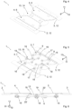
- Each of the scissor gates 9 is connected in a rotationally movable manner to both the first floor plate 4 and the second floor plate 5, more precisely to the floor plate undersides 7 of the floor plates 4, 5.
- the vehicle parts 2, 3 may be offset parallel to the height direction 11.
- the scissor gates 9 force a deflection or pivoting of the floor plates 4, 5, which ensures that the crossing remains unhindered.
- the scissor grilles 9 are indirectly connected to the first vehicle part 2 via the first base plate 4.
- the scissor grilles 9 are indirectly connected to the second vehicle part 3 via the second base plate 5. There is no direct connection between the scissor grilles 9 and the vehicle parts 2, 3.
- spherical bearings 16 are provided both for the rotatable connection of the scissor lattices 9 to the first base plate 4 and for the rotatable connection of the scissor lattices 9 to the second base plate 5.
- the scissor grilles 9 can be pushed apart and together like an accordion, whereby the most varied relative movements of the vehicle parts 2, 3 to each other with directional components parallel to the passage direction 8 and/or the width direction 10 and/or the height direction 11 can be taken into account.
- the base plate undersides 7 of the base plates 4, 5 can slide on sliding bodies 19 which are attached to the scissor grilles 9.
- the base plate undersides 7 rest on the sliding bodies 19 so that the scissor grilles 9 Support floor slabs 4, 5 and increase the stability of bridge 1 or the crossing.
- the sliding bodies 19 are made of plastic in the embodiments shown.
- the base plates 4, 5 and the scissor grilles 9 are made of metal, preferably an aluminum alloy, in the embodiments shown.
- the bridge 1 has, in addition to the floor plates 4, 5, a tread plate 13 with a tread plate upper side 14 that can be walked on at least in sections.
- this tread plate 13 is arranged behind the floor plates 4, 5 as seen in the height direction 11, wherein the tread plate 13 rests slidably on the floor plate upper sides 6 with support sections 20, cf. Fig.3
- the support sections 20 are made of a suitable plastic to improve the sliding properties.
- the tread plate 13 is arranged at least in sections between the floor plates 4, 5 when viewed parallel to the height direction 11, or sections of the first floor plate 4, the tread plate 13 and the second floor plate 5 are arranged next to one another when viewed parallel to the height direction 11.
- both scissor gates 9 are connected in a rotationally movable manner to a tread plate underside 15 opposite the tread plate upper side 14 in order to center the tread plate 13.
- the latter has the effect, particularly in the case of a lateral offset of the vehicle parts 2, 3 relative to one another (i.e. parallel to the passage direction 8 and/or to the width direction 10), that the tread plate 13 is positioned in such a way that it is still possible to walk on the bridge 1 without any problems.
- these rotatable connections between the scissor gate 9 and the tread plate 13 are each realized by a radial bearing 18, which allows radial bearing 18 to rotate about an axis of rotation that is normal to the underside of the tread plate 15, as well as to translate in a certain range parallel or along this axis of rotation.
- the second embodiment of the bridge 1 according to the invention shown is basically constructed exactly like the first embodiment, except that the tread plate 13 is arranged in front of the floor plates 4, 5 as seen in the height direction 11, wherein the floor plates 4, 5 rest slidably with support sections 20' on the tread plate upper side 14, cf. Fig.6
- the support sections 20' are made of a suitable plastic to improve the sliding properties.
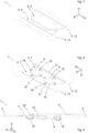
- the third embodiment of the bridge 1 according to the invention shown differs from the first two embodiments in that no step plate 13 is provided. This means that the Floor plates 4, 5 together cover the area between the two vehicle parts 2, 3.
- the second base plate 5 is arranged behind the first base plate 4 as seen in the height direction 11, wherein the second base plate 5 rests slidably on the base plate upper side 6 of the first base plate 4 with a support section 20".
- the support section 20" is made of a suitable plastic to improve the sliding properties.
- radial bearings 18 are provided in the third embodiment, see in particular Fig.9 , wherein the radial bearings 18 allow rotations about an axis of rotation perpendicular to the base plate underside 7 of the first base plate 4 as well as translations in a certain range parallel or along this axis of rotation.
- the rotatable connection of the scissor grilles 9 with the base plate underside 7 of the second base plate 5 is realized by spherical bearings 16, as in the other embodiments shown.
Landscapes
- Engineering & Computer Science (AREA)
- Mechanical Engineering (AREA)
- Life Sciences & Earth Sciences (AREA)
- Wood Science & Technology (AREA)
- Auxiliary Methods And Devices For Loading And Unloading (AREA)
- Bridges Or Land Bridges (AREA)
Priority Applications (3)
| Application Number | Priority Date | Filing Date | Title |
|---|---|---|---|
| PL21154115.6T PL4035911T3 (pl) | 2021-01-28 | 2021-01-28 | Mostek do przejścia pomiędzy dwiema częściami pojazdu, połączonymi ze sobą przegubowo |
| ES21154115T ES2982961T3 (es) | 2021-01-28 | 2021-01-28 | Puente para una transición entre dos secciones de vehículos con conexión articulada |
| EP21154115.6A EP4035911B1 (de) | 2021-01-28 | 2021-01-28 | Brücke für einen übergang zwischen zwei gelenkig miteinander verbundenen fahrzeugteilen |
Applications Claiming Priority (1)
| Application Number | Priority Date | Filing Date | Title |
|---|---|---|---|
| EP21154115.6A EP4035911B1 (de) | 2021-01-28 | 2021-01-28 | Brücke für einen übergang zwischen zwei gelenkig miteinander verbundenen fahrzeugteilen |
Publications (3)
| Publication Number | Publication Date |
|---|---|
| EP4035911A1 EP4035911A1 (de) | 2022-08-03 |
| EP4035911C0 EP4035911C0 (de) | 2024-06-05 |
| EP4035911B1 true EP4035911B1 (de) | 2024-06-05 |
Family
ID=74418152
Family Applications (1)
| Application Number | Title | Priority Date | Filing Date |
|---|---|---|---|
| EP21154115.6A Active EP4035911B1 (de) | 2021-01-28 | 2021-01-28 | Brücke für einen übergang zwischen zwei gelenkig miteinander verbundenen fahrzeugteilen |
Country Status (3)
| Country | Link |
|---|---|
| EP (1) | EP4035911B1 (pl) |
| ES (1) | ES2982961T3 (pl) |
| PL (1) | PL4035911T3 (pl) |
Families Citing this family (1)
| Publication number | Priority date | Publication date | Assignee | Title |
|---|---|---|---|---|
| EP4563435B1 (de) | 2023-12-01 | 2026-04-15 | Hübner GmbH & Co. KG | Übergangsbrücke zum bereitstellen eines übergangs zwischen einem ersten fahrzeugteil und einem zweiten fahrzeugteil eines fahrzeuges sowie fahrzeug mit einer solchen übergangsbrücke |
Family Cites Families (7)
| Publication number | Priority date | Publication date | Assignee | Title |
|---|---|---|---|---|
| FR2801536B1 (fr) * | 1999-11-26 | 2001-12-28 | Faiveley Transport | Plancher de circulation entre deux vehicules |
| CN101638098A (zh) * | 2009-01-21 | 2010-02-03 | 青岛欧特美股份有限公司 | 一种两车辆或车厢间连接处内侧的两片式侧护板 |
| JP5582983B2 (ja) | 2010-11-24 | 2014-09-03 | 楠本化成株式会社 | 水系沈降防止剤 |
| EP2457796B1 (de) * | 2010-11-26 | 2013-06-05 | Hübner GmbH | Brücke eines Übergangs zwischen zwei gelenkig miteinander verbundenen Fahrzeugen |
| KR101757805B1 (ko) * | 2015-06-09 | 2017-07-26 | 송한나 | 전동차의 객차간 통로 바닥 연결 장치 |
| CN206634007U (zh) * | 2017-03-22 | 2017-11-14 | 青岛欧特美交通装备有限公司 | 一种新型顶护板装置 |
| JP6450874B1 (ja) * | 2018-02-27 | 2019-01-09 | 株式会社成田製作所 | パネルの伸縮装置 |
-
2021
- 2021-01-28 PL PL21154115.6T patent/PL4035911T3/pl unknown
- 2021-01-28 ES ES21154115T patent/ES2982961T3/es active Active
- 2021-01-28 EP EP21154115.6A patent/EP4035911B1/de active Active
Also Published As
| Publication number | Publication date |
|---|---|
| EP4035911C0 (de) | 2024-06-05 |
| ES2982961T3 (es) | 2024-10-21 |
| EP4035911A1 (de) | 2022-08-03 |
| PL4035911T3 (pl) | 2024-08-12 |
Similar Documents
| Publication | Publication Date | Title |
|---|---|---|
| EP2500230B1 (de) | Brücke eines Übergangs zwischen zwei gelenkig miteinader verbundenen Fahrzeugteilen | |
| DE69623626T2 (de) | Türsystem | |
| EP3857002B1 (de) | Stützenkopf, deckenstütze, deckenschalung und verfahren zum errichten einer solchen deckenschalung | |
| EP3287305B1 (de) | Scherengestell und übergang mit scherengestell | |
| WO2012038143A1 (de) | Schiebetürantrieb | |
| EP4035911B1 (de) | Brücke für einen übergang zwischen zwei gelenkig miteinander verbundenen fahrzeugteilen | |
| DE102011116982A1 (de) | Lauf- und Arbeitsbühne | |
| EP3880916B1 (de) | Führungssystem zur führung zumindest eines bewegbar gelagerten möbelteiles | |
| EP0512123A1 (de) | Überbrückungsvorrichtung für Dehnungsfugen in Brücken oder dergleichen | |
| DE8916127U1 (de) | Vorrichtung zur federnden Einspannung von Traversen einer Fahrbahnüberbrückungskonstruktion | |
| EP2058456B1 (de) | Überdachung | |
| EP3046821A1 (de) | Übergangsplattform mit verwindungszonen | |
| EP0078484A1 (de) | Parkvorrichtung für Kraftfahrzeuge | |
| EP2562122B1 (de) | Rollenführung | |
| DE102011120071A1 (de) | Fahrbare Lagereinrichtung für eine mobile Dachkonstruktion | |
| EP3501863B1 (de) | Begehbare bodeneinrichtung für einen übergang | |
| DE102020201078B4 (de) | Bauwerksgleitlager und Bauwerkslagerungssystem | |
| EP2594450B1 (de) | Übergangshälfte zwischen zwei gelenkig miteinander verbundenen Fahrzeugen eines Schienenfahrzeugs | |
| DE102017007407B3 (de) | Fahrzeugkarosserie mit einer zwischen einer Geschlossenstellung und einer Offenstellung verschwenkbaren Seitentür | |
| EP1243215B1 (de) | Duschabtrennung | |
| DE69804669T2 (de) | Balkonverglasung | |
| DE102010055574B4 (de) | Modulares Brückenelement | |
| DE3805945A1 (de) | Schiebewand | |
| EP4019300B1 (de) | Seitenwandverkleidung | |
| EP3980600B1 (de) | Bauwerk |
Legal Events
| Date | Code | Title | Description |
|---|---|---|---|
| PUAI | Public reference made under article 153(3) epc to a published international application that has entered the european phase |
Free format text: ORIGINAL CODE: 0009012 |
|
| STAA | Information on the status of an ep patent application or granted ep patent |
Free format text: STATUS: THE APPLICATION HAS BEEN PUBLISHED |
|
| STAA | Information on the status of an ep patent application or granted ep patent |
Free format text: STATUS: REQUEST FOR EXAMINATION WAS MADE |
|
| AK | Designated contracting states |
Kind code of ref document: A1 Designated state(s): AL AT BE BG CH CY CZ DE DK EE ES FI FR GB GR HR HU IE IS IT LI LT LU LV MC MK MT NL NO PL PT RO RS SE SI SK SM TR |
|
| 17P | Request for examination filed |
Effective date: 20220714 |
|
| RBV | Designated contracting states (corrected) |
Designated state(s): AL AT BE BG CH CY CZ DE DK EE ES FI FR GB GR HR HU IE IS IT LI LT LU LV MC MK MT NL NO PL PT RO RS SE SI SK SM TR |
|
| RAP3 | Party data changed (applicant data changed or rights of an application transferred) |
Owner name: TEUFL, MANFRED Owner name: ULTIMATE EUROPE TRANSPORTATION EQUIPMENT GMBH |
|
| RAP3 | Party data changed (applicant data changed or rights of an application transferred) |
Owner name: TEUFL, MANFRED Owner name: ULTIMATE EUROPE TRANSPORTATION EQUIPMENT GMBH |
|
| GRAP | Despatch of communication of intention to grant a patent |
Free format text: ORIGINAL CODE: EPIDOSNIGR1 |
|
| STAA | Information on the status of an ep patent application or granted ep patent |
Free format text: STATUS: GRANT OF PATENT IS INTENDED |
|
| INTG | Intention to grant announced |
Effective date: 20240112 |
|
| GRAS | Grant fee paid |
Free format text: ORIGINAL CODE: EPIDOSNIGR3 |
|
| GRAA | (expected) grant |
Free format text: ORIGINAL CODE: 0009210 |
|
| STAA | Information on the status of an ep patent application or granted ep patent |
Free format text: STATUS: THE PATENT HAS BEEN GRANTED |
|
| AK | Designated contracting states |
Kind code of ref document: B1 Designated state(s): AL AT BE BG CH CY CZ DE DK EE ES FI FR GB GR HR HU IE IS IT LI LT LU LV MC MK MT NL NO PL PT RO RS SE SI SK SM TR |
|
| REG | Reference to a national code |
Ref country code: CH Ref legal event code: EP |
|
| REG | Reference to a national code |
Ref country code: DE Ref legal event code: R096 Ref document number: 502021003898 Country of ref document: DE |
|
| REG | Reference to a national code |
Ref country code: IE Ref legal event code: FG4D Free format text: LANGUAGE OF EP DOCUMENT: GERMAN |
|
| U01 | Request for unitary effect filed |
Effective date: 20240614 |
|
| U07 | Unitary effect registered |
Designated state(s): AT BE BG DE DK EE FI FR IT LT LU LV MT NL PT SE SI Effective date: 20240625 |
|
| PG25 | Lapsed in a contracting state [announced via postgrant information from national office to epo] |
Ref country code: HR Free format text: LAPSE BECAUSE OF FAILURE TO SUBMIT A TRANSLATION OF THE DESCRIPTION OR TO PAY THE FEE WITHIN THE PRESCRIBED TIME-LIMIT Effective date: 20240605 |
|
| PG25 | Lapsed in a contracting state [announced via postgrant information from national office to epo] |
Ref country code: GR Free format text: LAPSE BECAUSE OF FAILURE TO SUBMIT A TRANSLATION OF THE DESCRIPTION OR TO PAY THE FEE WITHIN THE PRESCRIBED TIME-LIMIT Effective date: 20240906 |
|
| REG | Reference to a national code |
Ref country code: ES Ref legal event code: FG2A Ref document number: 2982961 Country of ref document: ES Kind code of ref document: T3 Effective date: 20241021 |
|
| PG25 | Lapsed in a contracting state [announced via postgrant information from national office to epo] |
Ref country code: NO Free format text: LAPSE BECAUSE OF FAILURE TO SUBMIT A TRANSLATION OF THE DESCRIPTION OR TO PAY THE FEE WITHIN THE PRESCRIBED TIME-LIMIT Effective date: 20240905 Ref country code: HR Free format text: LAPSE BECAUSE OF FAILURE TO SUBMIT A TRANSLATION OF THE DESCRIPTION OR TO PAY THE FEE WITHIN THE PRESCRIBED TIME-LIMIT Effective date: 20240605 Ref country code: GR Free format text: LAPSE BECAUSE OF FAILURE TO SUBMIT A TRANSLATION OF THE DESCRIPTION OR TO PAY THE FEE WITHIN THE PRESCRIBED TIME-LIMIT Effective date: 20240906 Ref country code: RS Free format text: LAPSE BECAUSE OF FAILURE TO SUBMIT A TRANSLATION OF THE DESCRIPTION OR TO PAY THE FEE WITHIN THE PRESCRIBED TIME-LIMIT Effective date: 20240905 |
|
| PG25 | Lapsed in a contracting state [announced via postgrant information from national office to epo] |
Ref country code: IS Free format text: LAPSE BECAUSE OF FAILURE TO SUBMIT A TRANSLATION OF THE DESCRIPTION OR TO PAY THE FEE WITHIN THE PRESCRIBED TIME-LIMIT Effective date: 20241005 |
|
| PG25 | Lapsed in a contracting state [announced via postgrant information from national office to epo] |
Ref country code: CZ Free format text: LAPSE BECAUSE OF FAILURE TO SUBMIT A TRANSLATION OF THE DESCRIPTION OR TO PAY THE FEE WITHIN THE PRESCRIBED TIME-LIMIT Effective date: 20240605 |
|
| PG25 | Lapsed in a contracting state [announced via postgrant information from national office to epo] |
Ref country code: SK Free format text: LAPSE BECAUSE OF FAILURE TO SUBMIT A TRANSLATION OF THE DESCRIPTION OR TO PAY THE FEE WITHIN THE PRESCRIBED TIME-LIMIT Effective date: 20240605 Ref country code: RO Free format text: LAPSE BECAUSE OF FAILURE TO SUBMIT A TRANSLATION OF THE DESCRIPTION OR TO PAY THE FEE WITHIN THE PRESCRIBED TIME-LIMIT Effective date: 20240605 |
|
| PG25 | Lapsed in a contracting state [announced via postgrant information from national office to epo] |
Ref country code: SM Free format text: LAPSE BECAUSE OF FAILURE TO SUBMIT A TRANSLATION OF THE DESCRIPTION OR TO PAY THE FEE WITHIN THE PRESCRIBED TIME-LIMIT Effective date: 20240605 |
|
| PG25 | Lapsed in a contracting state [announced via postgrant information from national office to epo] |
Ref country code: SM Free format text: LAPSE BECAUSE OF FAILURE TO SUBMIT A TRANSLATION OF THE DESCRIPTION OR TO PAY THE FEE WITHIN THE PRESCRIBED TIME-LIMIT Effective date: 20240605 Ref country code: SK Free format text: LAPSE BECAUSE OF FAILURE TO SUBMIT A TRANSLATION OF THE DESCRIPTION OR TO PAY THE FEE WITHIN THE PRESCRIBED TIME-LIMIT Effective date: 20240605 Ref country code: RO Free format text: LAPSE BECAUSE OF FAILURE TO SUBMIT A TRANSLATION OF THE DESCRIPTION OR TO PAY THE FEE WITHIN THE PRESCRIBED TIME-LIMIT Effective date: 20240605 Ref country code: IS Free format text: LAPSE BECAUSE OF FAILURE TO SUBMIT A TRANSLATION OF THE DESCRIPTION OR TO PAY THE FEE WITHIN THE PRESCRIBED TIME-LIMIT Effective date: 20241005 Ref country code: CZ Free format text: LAPSE BECAUSE OF FAILURE TO SUBMIT A TRANSLATION OF THE DESCRIPTION OR TO PAY THE FEE WITHIN THE PRESCRIBED TIME-LIMIT Effective date: 20240605 |
|
| U20 | Renewal fee for the european patent with unitary effect paid |
Year of fee payment: 5 Effective date: 20250127 |
|
| PLBE | No opposition filed within time limit |
Free format text: ORIGINAL CODE: 0009261 |
|
| STAA | Information on the status of an ep patent application or granted ep patent |
Free format text: STATUS: NO OPPOSITION FILED WITHIN TIME LIMIT |
|
| 26N | No opposition filed |
Effective date: 20250306 |
|
| REG | Reference to a national code |
Ref country code: CH Ref legal event code: PL |
|
| PG25 | Lapsed in a contracting state [announced via postgrant information from national office to epo] |
Ref country code: MC Free format text: LAPSE BECAUSE OF FAILURE TO SUBMIT A TRANSLATION OF THE DESCRIPTION OR TO PAY THE FEE WITHIN THE PRESCRIBED TIME-LIMIT Effective date: 20240605 |
|
| PG25 | Lapsed in a contracting state [announced via postgrant information from national office to epo] |
Ref country code: CH Free format text: LAPSE BECAUSE OF NON-PAYMENT OF DUE FEES Effective date: 20250131 |
|
| PG25 | Lapsed in a contracting state [announced via postgrant information from national office to epo] |
Ref country code: IE Free format text: LAPSE BECAUSE OF NON-PAYMENT OF DUE FEES Effective date: 20250128 |
|
| PGFP | Annual fee paid to national office [announced via postgrant information from national office to epo] |
Ref country code: PL Payment date: 20251223 Year of fee payment: 6 |
|
| U20 | Renewal fee for the european patent with unitary effect paid |
Year of fee payment: 6 Effective date: 20260123 |
|
| PGFP | Annual fee paid to national office [announced via postgrant information from national office to epo] |
Ref country code: GB Payment date: 20260126 Year of fee payment: 6 |
|
| PGFP | Annual fee paid to national office [announced via postgrant information from national office to epo] |
Ref country code: ES Payment date: 20260210 Year of fee payment: 6 |
|
| PGFP | Annual fee paid to national office [announced via postgrant information from national office to epo] |
Ref country code: TR Payment date: 20260109 Year of fee payment: 6 |