EP4035690B1 - Anordnung zur emission von ultraviolettem licht - Google Patents
Anordnung zur emission von ultraviolettem licht Download PDFInfo
- Publication number
- EP4035690B1 EP4035690B1 EP21210728.8A EP21210728A EP4035690B1 EP 4035690 B1 EP4035690 B1 EP 4035690B1 EP 21210728 A EP21210728 A EP 21210728A EP 4035690 B1 EP4035690 B1 EP 4035690B1
- Authority
- EP
- European Patent Office
- Prior art keywords
- light
- light emitter
- emitter support
- heat sink
- support
- Prior art date
- Legal status (The legal status is an assumption and is not a legal conclusion. Google has not performed a legal analysis and makes no representation as to the accuracy of the status listed.)
- Active
Links
Images


Classifications
-
- B—PERFORMING OPERATIONS; TRANSPORTING
- B64—AIRCRAFT; AVIATION; COSMONAUTICS
- B64D—EQUIPMENT FOR FITTING IN OR TO AIRCRAFT; FLIGHT SUITS; PARACHUTES; ARRANGEMENT OR MOUNTING OF POWER PLANTS OR PROPULSION TRANSMISSIONS IN AIRCRAFT
- B64D11/00—Passenger or crew accommodation; Flight-deck installations not otherwise provided for
- B64D11/02—Toilet fittings
-
- A—HUMAN NECESSITIES
- A61—MEDICAL OR VETERINARY SCIENCE; HYGIENE
- A61L—METHODS OR APPARATUS FOR STERILISING MATERIALS OR OBJECTS IN GENERAL; DISINFECTION, STERILISATION OR DEODORISATION OF AIR; CHEMICAL ASPECTS OF BANDAGES, DRESSINGS, ABSORBENT PADS OR SURGICAL ARTICLES; MATERIALS FOR BANDAGES, DRESSINGS, ABSORBENT PADS OR SURGICAL ARTICLES
- A61L2/00—Disinfection or sterilisation of materials or objects, in general; Accessories therefor
- A61L2/02—Disinfection or sterilisation of materials or objects, in general; Accessories therefor using physical processes
- A61L2/08—Radiation
- A61L2/10—Ultraviolet [UV] radiation
-
- A—HUMAN NECESSITIES
- A61—MEDICAL OR VETERINARY SCIENCE; HYGIENE
- A61L—METHODS OR APPARATUS FOR STERILISING MATERIALS OR OBJECTS IN GENERAL; DISINFECTION, STERILISATION OR DEODORISATION OF AIR; CHEMICAL ASPECTS OF BANDAGES, DRESSINGS, ABSORBENT PADS OR SURGICAL ARTICLES; MATERIALS FOR BANDAGES, DRESSINGS, ABSORBENT PADS OR SURGICAL ARTICLES
- A61L2/00—Disinfection or sterilisation of materials or objects, in general; Accessories therefor
- A61L2/24—Apparatus using programmed or automatic operation
-
- A—HUMAN NECESSITIES
- A61—MEDICAL OR VETERINARY SCIENCE; HYGIENE
- A61L—METHODS OR APPARATUS FOR STERILISING MATERIALS OR OBJECTS IN GENERAL; DISINFECTION, STERILISATION OR DEODORISATION OF AIR; CHEMICAL ASPECTS OF BANDAGES, DRESSINGS, ABSORBENT PADS OR SURGICAL ARTICLES; MATERIALS FOR BANDAGES, DRESSINGS, ABSORBENT PADS OR SURGICAL ARTICLES
- A61L2/00—Disinfection or sterilisation of materials or objects, in general; Accessories therefor
- A61L2/26—Accessories
-
- F—MECHANICAL ENGINEERING; LIGHTING; HEATING; WEAPONS; BLASTING
- F21—LIGHTING
- F21V—FUNCTIONAL FEATURES OR DETAILS OF LIGHTING DEVICES OR SYSTEMS THEREOF; STRUCTURAL COMBINATIONS OF LIGHTING DEVICES WITH OTHER ARTICLES, NOT OTHERWISE PROVIDED FOR
- F21V21/00—Supporting, suspending, or attaching arrangements for lighting devices; Hand grips
- F21V21/14—Adjustable mountings
-
- F—MECHANICAL ENGINEERING; LIGHTING; HEATING; WEAPONS; BLASTING
- F21—LIGHTING
- F21V—FUNCTIONAL FEATURES OR DETAILS OF LIGHTING DEVICES OR SYSTEMS THEREOF; STRUCTURAL COMBINATIONS OF LIGHTING DEVICES WITH OTHER ARTICLES, NOT OTHERWISE PROVIDED FOR
- F21V23/00—Arrangement of electric circuit elements in or on lighting devices
- F21V23/003—Arrangement of electric circuit elements in or on lighting devices the elements being electronics drivers or controllers for operating the light source, e.g. for a LED array
-
- F—MECHANICAL ENGINEERING; LIGHTING; HEATING; WEAPONS; BLASTING
- F21—LIGHTING
- F21V—FUNCTIONAL FEATURES OR DETAILS OF LIGHTING DEVICES OR SYSTEMS THEREOF; STRUCTURAL COMBINATIONS OF LIGHTING DEVICES WITH OTHER ARTICLES, NOT OTHERWISE PROVIDED FOR
- F21V29/00—Protecting lighting devices from thermal damage; Cooling or heating arrangements specially adapted for lighting devices or systems
- F21V29/50—Cooling arrangements
- F21V29/70—Cooling arrangements characterised by passive heat-dissipating elements, e.g. heat-sinks
- F21V29/74—Cooling arrangements characterised by passive heat-dissipating elements, e.g. heat-sinks with fins or blades
-
- H—ELECTRICITY
- H05—ELECTRIC TECHNIQUES NOT OTHERWISE PROVIDED FOR
- H05K—PRINTED CIRCUITS; CASINGS OR CONSTRUCTIONAL DETAILS OF ELECTRIC APPARATUS; MANUFACTURE OF ASSEMBLAGES OF ELECTRICAL COMPONENTS
- H05K7/00—Constructional details common to different types of electric apparatus
- H05K7/20—Modifications to facilitate cooling, ventilating, or heating
- H05K7/2039—Modifications to facilitate cooling, ventilating, or heating characterised by the heat transfer by conduction from the heat generating element to a dissipating body
- H05K7/20509—Multiple-component heat spreaders; Multi-component heat-conducting support plates; Multi-component non-closed heat-conducting structures
-
- A—HUMAN NECESSITIES
- A61—MEDICAL OR VETERINARY SCIENCE; HYGIENE
- A61L—METHODS OR APPARATUS FOR STERILISING MATERIALS OR OBJECTS IN GENERAL; DISINFECTION, STERILISATION OR DEODORISATION OF AIR; CHEMICAL ASPECTS OF BANDAGES, DRESSINGS, ABSORBENT PADS OR SURGICAL ARTICLES; MATERIALS FOR BANDAGES, DRESSINGS, ABSORBENT PADS OR SURGICAL ARTICLES
- A61L2103/00—Materials or objects being the target of disinfection or sterilisation
- A61L2103/75—Room floors or walls
-
- A—HUMAN NECESSITIES
- A61—MEDICAL OR VETERINARY SCIENCE; HYGIENE
- A61L—METHODS OR APPARATUS FOR STERILISING MATERIALS OR OBJECTS IN GENERAL; DISINFECTION, STERILISATION OR DEODORISATION OF AIR; CHEMICAL ASPECTS OF BANDAGES, DRESSINGS, ABSORBENT PADS OR SURGICAL ARTICLES; MATERIALS FOR BANDAGES, DRESSINGS, ABSORBENT PADS OR SURGICAL ARTICLES
- A61L2202/00—Aspects relating to methods or apparatus for disinfecting or sterilising materials or objects
- A61L2202/10—Apparatus features
- A61L2202/11—Apparatus for generating biocidal substances, e.g. vaporisers, UV lamps
-
- E—FIXED CONSTRUCTIONS
- E03—WATER SUPPLY; SEWERAGE
- E03D—WATER-CLOSETS OR URINALS WITH FLUSHING DEVICES; FLUSHING VALVES THEREFOR
- E03D9/00—Sanitary or other accessories for lavatories ; Devices for cleaning or disinfecting the toilet room or the toilet bowl; Devices for eliminating smells
- E03D9/002—Automatic cleaning devices
Definitions
- This disclosure generally relates to disinfecting surfaces, and more particularly to assemblies and methods for disinfecting surfaces using ultraviolet (UV) light.
- UV ultraviolet
- UV light has been used in some settings to disinfect and sanitize surfaces.
- multiple UV emitters are provided and powered by a relatively low power supply, such as 12 watts. While such UV devices offer promise in their ability to render inactive and/or kill certain pathogens, challenges exist in developing devices and systems for more effective delivery of such UV radiation.
- WO 2015/028334 A1 in accordance with its abstract, states a light emitting device, and a method for manufacturing it.
- the method comprises the steps of, in the order mentioned: providing at least one substrate and at least one solid state light source, arranging the at least one solid state light source on the at least one substrate, providing a light guide comprising a light input surface and a light exit surface extending in an angle different from zero to one another, shaping the light guide to provide at least one cavity in the light input surface which is shaped such that it can accommodate the at least one solid state light source, mounting the at least one substrate with the at least one solid state light source arranged thereon onto the light guide and accommodating the at least one solid state light source in the at least one cavity such that the at least one solid state light source is at least partly embedded in the light guide to form a light emitting device body, and encapsulating the light emitting device body partially in an envelope such that the light emitting device body and the envelope are in physical contact to form a light emitting device and such that the light exit surface of
- JP 2018/167166 A in accordance with its abstract, states the light irradiation device that includes: a first light source part comprising a plurality of first ultraviolet LED elements arranged on a plane; and a second light source part at a position adjoining to the first light source part in the first direction, comprising a plurality of second ultraviolet LED elements arranged on a plane.
- the plurality of first ultraviolet LED elements and the plurality of second ultraviolet LED elements have the same main emission wavelength when lit under the same conditions, while temperature characteristics of the first light source part are different from temperature characteristics of the second light source part.
- CN 211204004 U in accordance with its abstract, states an illumination and bacteriostasis integrated lamp including a base, a connecting groove that is formed in the lower end of the base; a fluorescent lamp and an ultraviolet germicidal lamp are respectively arranged in the connecting groove; a transparent cover is arranged at the lower end of the base; the transparent cover is filled with a light-emitting layer.
- the upper end of the transparent cover is fixedly connected with the side wall of the lower end of the base; a storage groove is formed in the upper end of the base; a cooling hole is formed between the storage groove and the connecting groove; a semiconductor chilling plate is fixedly connected to the side wall of the inner bottom end of the storage groove, the refrigeration end of the semiconductor chilling plate abuts against the side wall of the inner bottom end of the storage groove, a heat conduction plate is fixedly connected to the upper end of the semiconductor chilling plate, a heat dissipation pipe is fixedly connected to the upper end of the heat conduction plate, and the upper end of the heat dissipation pipe penetrates through the heat dissipation fins.
- Buonanno Manuela et al "Far-UVC light (222 nm) efficiently and safely inactivates airborne human coronaviruses", Scientific reports, Vol. 10, No. 1, December 1, 2020 , in accordance with its abstracts, states that 222-nm far-UVC light efficiently kills airborne influenza virus and airborne human coronaviruses, with a low dose of 1,7 and 1,2 mJ/cm 2 .
- an ultraviolet (UV) light-emitting assembly is provided in accordance with claim 1.
- a method for varying UV intensity emitted by a plurality of UV light emitters is provided in accordance with 13.
- FIGS. 1 and 2 show one example of a system for disinfecting one or more components using ultraviolet (UV) light-emitting assemblies of the present disclosure.
- the system utilizes UV light-emitting assemblies incorporating one or more heat sinks that provide heat transfer functionality to enable the assemblies to operate at higher power and provide correspondingly higher UV irradiation.
- the assemblies may be mechanically controlled to vary the UV light intensity emitted by the UV light emitters.
- FIG. 1 illustrates a perspective view of a lavatory 102 that includes a system 100 for disinfecting one or more components using ultraviolet (UV) light.
- the system 100 includes a plurality of UV light-emitting modules 104 containing UV light-emitting assemblies as described further below.
- the system 100 also includes a power supply module 106 that is electrically connected to each of the UV light-emitting modules 104 and provides power to the UV light-emitting assemblies inside the modules to generate UV light for disinfecting and/or sanitizing components and their surfaces in the lavatory 102.
- the system 100 utilizes fewer or more than three UV light-emitting modules 104 that are electrically connected to the power supply module 106.
- the system 100 and/or individually powered UV light-emitting modules 104 can be utilized in a variety of environments, including but not limited to kitchens, galleys, retail establishments, medical facilities, arenas, places of worship, banquet halls, theatres, concert venues, commercial businesses, factories, and other spaces.
- the system 100 and/or individually powered UV light-emitting modules 104 can be utilized in aircraft, spacecraft, and other vehicles, such as buses, trains, marine vessels, and the like.
- the system 100 can be located within a cabin, galley, crew rest area, assembly area, cargo area, flight deck, lavatory, and other areas in which individuals, passengers, flight crew, ground crew, and/or maintenance personnel may be located.
- the lavatory 102 can be located within a vehicle, such as within a cabin of a commercial aircraft.
- FIG. 15 depicts an aircraft environment in which UV light-emitting modules 104 are installed above passenger seats 1004 in the cabin 1000 of the aircraft.
- FIGS. 2 and 3 illustrate one example of a module 104 in which UV light-emitting assemblies of the present disclosure may be enclosed.
- Module 104 is provided merely as one example, and any suitable housing or enclosure may be utilized with the UV light-emitting assemblies described herein.
- one or more UV light-emitting assemblies may be utilized in a portable device, such as a wand, that is configured to be held by a user.
- a portable device is also configured to be removably mounted to a support structure, such as a wall.
- the UV light-emitting modules 104 are positioned to emit the UV light towards one or more components within the lavatory 102 for disinfecting and/or sanitizing the components.
- the one or more components include a sink 112 and a toilet 110.
- the UV light-emitting modules 104 are positioned to emit UV light towards different components.
- the first UV light-emitting module 104a is positioned to emit UV light towards the toilet 110 including a flush actuator 114 (e.g., lever, button, etc.) of the toilet 110.
- the second UV light-emitting module 104b is positioned to emit UV light towards the sink 112 and the surrounding region, such as portions of the faucet 116 and countertop 118.
- the third UV light-emitting module 104c is positioned to emit UV light towards the door (not shown) used to enter and exit the lavatory 102.
- two or more UV light-emitting modules 104 are positioned to emit UV light towards a common component. In some examples, two or more UV light-emitting modules 104 are physically adjacent and/or mechanically coupled to one another.
- the power supply module 106 is electrically connected to the UV light-emitting modules 104 to provide power to the UV light-emitting assemblies therein.
- the power supply module 106 includes processing and/or power modulation circuitry within an enclosure or housing.
- the power supply module 106 receives electrical energy from a power source, such as power distribution panel or a battery, and distributes the electrical energy among the UV light-emitting modules 104.
- the power supply module 106 is mounted within the lavatory 102 and is electrically connected to the UV light-emitting modules 104 via respective power leads 120, such as one or more electrical wires or power cables.
- respective power leads 120 such as one or more electrical wires or power cables.
- one or more of the UV light-emitting modules 104 are integrated with the power supply module 106 in a common housing.
- Figure 2 illustrates a schematic block diagram of the system 100 according to an example of the present disclosure.
- the power supply module 106 receives electrical energy from an external power source 202 that is separate and discrete from the power supply module 106.
- the power source 202 is a vehicle electrical system onboard a vehicle or an electrical system of a building or facility.
- the power source 202 is a battery, a generator, or the like.
- the power supply module 106 is electrically connected to the external power source 202 via a power conditioning circuit 204 and power cables 206 and 208.
- the power conditioning circuit 204 includes one or more rectifiers, power factor correction circuits, and/or capacitors for electromagnetic interference filtering.
- the power conditioning circuit 204 is integrated with the power supply module 106 in a common enclosure, such as a housing of the power supply module.
- the power supply module 106 receives electrical energy from the power conditioning circuit 204 and controls distribution of the electrical energy among the UV light-emitting modules 104.
- the power conditioning circuit 204 receives alternating current (AC) electrical energy from the external power source 202 and converts the AC electrical energy to DC electrical energy.
- AC alternating current
- This DC electrical energy is supplied to the power supply module 106, which converts the DC electrical energy to AC electrical energy and supplies the AC to the UV light-emitting modules 104 to power the generation of UV light as described in more detail below.
- the power supply module 106 also controls one or more operations of the UV light-emitting modules 104, such as activating and deactivating the modules, and modulating the power output of the modules.
- UV light-emitting assemblies of the present disclosure utilize one or more heat sinks that enable the modules to operate at higher power and provide correspondingly higher UV irradiation than prior UV emitters. Additionally, and in some examples described below, one or more moving mechanisms are utilized to vary the UV light intensity emitted by the UV light emitters of an assembly.
- UV light-emitting assembly 300 can be enclosed in module 104 described above and shown in FIG. 3 , or in a variety of other housings, enclosures, or portable devices.
- the UV light-emitting assembly 300 and the other examples of UV light-emitting assemblies described herein can be utilized in a UV disinfecting system, such as system 100, and/or in standalone devices.
- the UV light-emitting assembly 300 is housed in module 104 that comprises a face plate 312 including a light-transmitting aperture 316 through which UV light from one or more UV light emitters within the enclosure is transmitted.
- the walls of the module 104 can be fabricated from a plastic material or from a conductive material, such as aluminum.
- the UV light-emitting assembly 300 utilizes four UV light emitters 320. In other examples, fewer or more than four UV light emitters may be utilized in UV light-emitting assemblies according to the present disclosure.
- the plurality of UV light emitters 320 is configured to emit 222 nm wavelength UV light.
- the UV light emitters 320 are excimer lamps that utilize a krypton-chlorine (Kr-Cl) gas mixture provided in the lamp bulb. Such excimer lamps emit UV light having a wavelength of 222 nm that can disinfect and sanitize component surfaces via localized anti-viral and antimicrobial effects. Further, 222 nm wavelength UV light can disinfect and sanitize surfaces without skin damaging effects associated with conventional germicidal ultraviolet (UV) exposure.
- the UV light-emitting assembly 300 can utilize other types of UV emitters and UV lamps. Additionally, and as described in more detail below, the UV light emitters 320 are seated in one or more UV light emitter supports within the module 104.
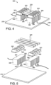
- the UV light emitters 320 are seated in V-shaped grooves in a first UV light emitter support 322 and a second UV light emitter support 323 that extend parallel to one another.
- the UV light emitter supports 322, 323 are fabricated from a conductive material, such as aluminum. In this manner and by seating the UV light emitters 320 in the supports, the emitters are electrically coupled to the supports.
- heat sinks 346 and 380 provide heat transfer functionality that enables the assembly 300 to operate at higher powers and provide correspondingly higher UV irradiation.
- heat sinks 346 and 380 in combination with increased gaps between the UV light emitter supports 322, 323 generates significantly increased UV light intensity and larger irradiance areas as compared to prior configurations. In this manner, fewer UV light assemblies may be utilized to sterilize a given area.
- the first heat sink 346 comprises a first plurality of fins 350 extending from a first base portion 354 of the first heat sink.
- the first base portion is affixed to a first bottom face 356 of the first UV light emitter support 322.
- the second heat sink 380 comprises a second plurality of fins 384 extending from a second base portion 386 of the second heat sink.
- the second base portion 386 is affixed to a second bottom face 388 of the second UV light emitter support 323.
- the UV light emitter supports and heat sinks are separate components that are affixed to one another.
- the heat sink and UV light emitter support are produced from a single material source or material, such as via metalworking or additive manufacturing.
- each fin 350 of the first plurality of fins comprises a first distal end 352 opposite to the first base portion 354, and these first distal ends are contacting a thermally conductive and electrically insulating plate 370.
- each fin 384 of the second plurality of fins comprises a second distal end 390 opposite to the second base portion 386, with these second distal ends also contacting the thermally conductive and electrically insulating plate 370.
- the thermally conductive and electrically insulating plate 370 is fabricated from a fluoropolymer material, such as polytetrafluoroethylene (PTFE).
- the thermal conductivity of the plate 370 further facilitates heat transfer from the UV light emitter supports 322, 323 via first heat sink 346 and second heat sink 380 to cool the UV light emitters 320.
- fluoropolymer materials have properties that reflect 222 nm UV light. Accordingly, this configuration also provides a larger surface area of 222 nm UV light reflective material from which UV light emitted by the UV light emitters 320 is reflected.
- first UV light emitter support 322 and second UV light emitter support 323 can be widened to maximize the amount of gas mixture in the light emitter bulbs that is excited, and thereby increase the emitted UV light.
- first UV light emitter support 322 and second UV light emitter support 323 are positioned with a gap 377 that places both ends of each of the UV light emitters 320 substantially flush with the first outer side 357 and the second outer side 359 of the UV light emitter support 322, 323, respectively.
- the gap 377 between first UV light emitter support 322 and second UV light emitter support 323 can be significantly wider than in prior configurations.
- the gap 377 is approximately 17 mm.
- the power supplied to the UV light-emitting assembly 300 is 100 W, the assembly generates approximately 9 mW/cm 2 over approximately 29.4 cm 2 .
- this example area irradiated by UV light is approximately 29% larger than the area irradiated by the same components configured with a 6 mm gap between first UV light emitter support 322 and second UV light emitter support 323.
- gaps between the first UV light emitter support 322 and second UV light emitter support 323 can be greater than 17 mm.
- the first UV light emitter support 322 comprises a first inner support face 360 that faces a second inner support face 392 of the second UV light emitter support 323.
- the first heat sink 346 comprises a first inner heat sink face 362 (including inner surfaces of the fins 350) that faces a second inner heat sink face 394 (including inner surfaces of the fins 384) of the second heat sink 380.
- the first inner support face 360 is substantially flush with the first inner heat sink face 362, and the second inner support face 392 is substantially flush with the second inner heat sink face 394.
- this configuration prevents electrical arcing between the first heat sink 346 and second heat sink 380.
- the UV light emitter supports 322, 323 are fabricated from a conductive material, such as aluminum, the supports are electrically coupled to a power source via lead wires 365 and 395, respectively.
- the power source is the power supply module 106 of system 100.
- the UV light emitter supports 322, 323 can be fabricated from a fluoropolymer, such as polytetrafluoroethylene (PTFE).
- PTFE polytetrafluoroethylene
- the UV light emitters 320 are directly coupled to a power source via lead wires connected to terminals at each end of the of the emitters.
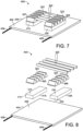
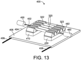
- a UV light-emitting assembly 400 of the present disclosure utilizes a heat sink in the form of an actively-cooled plate 404.
- the actively-cooled plate 404 is fabricated from a thermally-conductive material, such as aluminum, and includes embedded tubing 408 through which liquid coolant is circulated.
- a variety of materials, heat-exchanging technologies, and configurations can be utilized for the actively-cooled plate 404.
- thermally conductive and electrically insulating pads are located between the UV light-emitting supports and the actively-cooled plate 404.
- a first thermally conductive and electrically insulating pad 410 includes a first upper face 414 that contacts and is affixed to the first bottom face 356 of first UV light-emitting support 322.
- the first thermally conductive and electrically insulating pad 410 also includes a first lower face 418 that contacts an upper surface 406 of the actively-cooled plate 404.
- a second thermally conductive and electrically insulating pad 430 includes a second upper face 434 that contacts and is affixed to the second bottom face 388 of second UV light-emitting support 322, and a second lower face 438 that contacts the upper surface 406 of the actively-cooled plate 404.
- the actively-cooled plate 404 in combination with the first and second thermally conductive and electrically insulating pads 410, 430 operates to transfer heat from the first and second UV light-emitting supports 322, 323.
- the gap between first UV light emitter support 322 and second UV light emitter support 323 can be widened to maximize the amount of gas mixture in the light emitter bulbs that is excited, and thereby increase the emitted UV light. In this respect and as shown in FIG.
- the first UV light emitter support 322 and second UV light emitter support 323 are spaced apart to create a gap that places both ends of each of the UV light emitters 320 substantially flush with the first outer side 357 and the second outer side 359 of the UV light emitter support 322, 323, respectively.
- the aluminum UV light emitter supports 322, 323 can be electrically coupled to a power source in any suitable manner.
- the UV light emitters 320 are directly coupled to a power source via lead wires connected to terminals at each end of the of the emitters.
- the UV light emitter supports 322, 323 can be fabricated from a fluoropolymer, such as polytetrafluoroethylene (PTFE).
- PTFE polytetrafluoroethylene
- the UV light emitters 320 are directly coupled to a power source via lead wires connected to terminals at each end of the of the emitters.
- assemblies of the present disclosure also are configured to enable real-time variation of the gap between the first UV light emitter support 322 and the second UV light emitter support 323, and thereby vary the UV light intensity of UV light emitted from the UV light emitters.
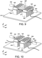
- the UV light-emitting assembly 300 of FIGS. 4 and 5 also comprises a moving mechanism in the form of a first actuator 450 and second actuator 460.
- the first actuator 450 and second actuator 460 are configured to translate the first heat sink 346 and the second heat sink 380, respectively, relative to the thermally conductive and electrically insulating plate 370.
- the first actuator 450 includes a first rod 452 that is coupled to the first light emitter support 322.
- the first actuator 450 is controlled to translate the first light emitter support 322 and attached first heat sink 346 in a positive and negative x-axis direction.
- the second actuator 460 includes a second rod 462 that is coupled to the second light emitter support 323.
- the second actuator 460 is also controlled to translate the second light emitter support 323 and attached second heat sink 380 in a positive and negative x-axis direction.
- the first actuator 450 is controlled to translate the first UV light emitter support 322 and first heat sink 346 in a positive x-axis direction
- the second actuator 460 is controlled translate the second UV light emitter support 323 and second heat sink 380 in a negative x-axis direction to narrow the gap 377 between the two UV light emitter supports and heat sinks.
- the first and second UV light emitter supports 322, 323 are moved, they slide underneath the UV light emitters 320 such that the ends of the emitters protrude beyond the first outer side 357 and second outer side 359 of the UV light emitter support 322, 323, respectively, as shown in FIG. 10 .
- the distance between electrical coupling locations on each UV light emitter 320 is also narrowed. In this manner, less of the gas mixture in the light emitter bulbs is excited, and the emitted UV light is reduced as compared to the wider gap 377 of FIG. 9 .
- the frequency, voltage and/or other characteristics of the power supplied to the first and second UV light emitter supports 322, 323 also can be adjusted to vary the intensity of emitted UV light.
- the first actuator 450 and/or second actuator 460 can be controlled to widen or narrow the gap between the two UV light emitter supports and heat sinks to thereby vary the UV light intensity of UV light emitted from the UV light emitters as desired.
- the moving mechanism is configured to translate only the first UV light emitter support 322 or the second UV light emitter support 323.
- a single actuator 464 is configured to extend and retract rod 466 to translate the second UV light emitter support 323 toward and away from the first UV light emitter support 322 to vary the gap 377 as desired.
- the actuators described herein can be any suitable type of motion control component, including but not limited to servo motors, stepper motors, and solenoids.
- any other suitable motion control or motion imparting components may be utilized to translate one or more of the UV light emitter supports, including but not limited to gearing mechanisms, chain drives, and belt drives.
- the UV light-emitting assembly 400 of FIGS. 7 and 8 also comprises a moving mechanism in the form of first actuator 450 and second actuator 460.
- first actuator 450 is configured to translate the first UV light emitter support 322 and first thermally conductive and electrically insulating pad 410 relative to the actively-cooled plate 404
- second actuator 460 is configured to translate the second UV light emitter support 323 and second thermally conductive and electrically insulating pad 430 relative to the actively-cooled plate.
- moving the first and second UV light emitter supports 322, 323 underneath the UV light emitters 320 changes the distance between electrical coupling locations on each UV light emitter 320, and correspondingly changes the intensity of emitted UV light.
- the assemblies can utilize any suitable combinations of features described herein, including but not limited to heat sink features, component materials, and moving mechanisms.
- FIG. 14 a method 500 for varying UV light intensity emitted by a plurality of krypton-chlorine (Kr-Cl) excimer lamps emitting UV light is illustrated. The method 500 is performed using a first UV light emitter support seating the plurality of UV light emitters and a second UV light emitter support seating the plurality of UV light emitters, wherein the first UV light emitter support is spaced from the second UV light emitter support.
- Kr-Cl krypton-chlorine
- method 500 includes the step of energizing the plurality of UV light emitters to emit a first UV light intensity when the first UV light emitter support is spaced from the second UV light emitter support by a first gap.
- the method 500 includes the step of moving the first UV light emitter support away from the second UV light emitter support until the first UV light emitter support is spaced from the second UV light emitter support by a second gap greater than the first gap.
- the method 500 includes energizing the plurality of UV light emitters to emit a second UV light intensity greater than the first UV light intensity when the first UV light emitter support is spaced from the second UV light emitter support by the second gap.
- the method 500 includes the step of translating the first UV light emitter support in a first direction and translating the second UV light emitter support in a second direction opposite to the first direction.
- the method 500 includes translating only the first UV light emitter support.
- the moving mechanism may be configured to translate the first heat sink relative to the thermally conductive and electrically insulating plate and to translate the second heat sink relative to the thermally conductive and electrically insulating plate.
Landscapes
- Health & Medical Sciences (AREA)
- Engineering & Computer Science (AREA)
- Animal Behavior & Ethology (AREA)
- Epidemiology (AREA)
- Life Sciences & Earth Sciences (AREA)
- General Health & Medical Sciences (AREA)
- Public Health (AREA)
- Veterinary Medicine (AREA)
- General Engineering & Computer Science (AREA)
- Microelectronics & Electronic Packaging (AREA)
- Physics & Mathematics (AREA)
- Thermal Sciences (AREA)
- Aviation & Aerospace Engineering (AREA)
- Led Device Packages (AREA)
- Apparatus For Disinfection Or Sterilisation (AREA)
Claims (15)
- Anordnung zur Emission von UV-Licht (300, 400) zur Desinfektion eines oder mehrerer Bauteile, wobei die Anordnung aufweist:eine Vielzahl von Krypton-Chlor (Kr-Cl)-Excimer-Lampen (320), die UV-Licht emittieren;einen ersten UV-Licht-Emitter-Träger (322) aus einem leitenden Material;einen zweiten UV-Licht-Emitter-Träger (323) aus einem leitenden Material, der von dem ersten UV-Licht-Emitter-Träger (322) beabstandet ist, wobei jeder der Vielzahl von UV-Licht-Emitter (320) in dem ersten und zweiten UV-Licht-Emitter-Träger (322, 323) sitzt;eine erste Wärmesenke (346), die an dem ersten UV-Licht-Emitter-Träger (322) befestigt ist;eine zweite Wärmesenke (380), die an dem zweiten UV-Licht-Emitter-Träger (323) befestigt ist;eine wärmeleitende und elektrisch isolierende Platte (370), die die erste Wärmesenke (346) und die zweite Wärmesenke (380) berührt; undeinen Bewegungsmechanismus, welcher derart konfiguriert ist, dass er einen Spalt (377) zwischen dem ersten UV-Licht-Emitter-Träger (322) und dem zweiten UV-Licht-Emitter-Träger (323) verändert.
- Anordnung zur Emission von UV-Licht nach Anspruch 1, wobei die erste Wärmesenke (346) eine erste Vielzahl von Rippen (350) aufweist, die sich von einem ersten Basisabschnitt (354) der ersten Wärmesenke (346) erstrecken, und die zweite Wärmesenke (380) eine zweite Vielzahl von Rippen (384) aufweist, die sich von einem zweiten Basisabschnitt (386) der zweiten Wärmesenke (380) erstrecken.
- Anordnung zur Emission von UV-Licht nach Anspruch 2, wobei der erste Basisabschnitt (354) an einer ersten Unterseite (356) des ersten UV-Licht-Emitter-Trägers (322) befestigt ist und der zweite Basisabschnitt (386) an einer zweiten Unterseite (388) des zweiten UV-Licht-Emitter-Trägers (323) befestigt ist.
- Anordnung zur Emission von UV-Licht nach Anspruch 3, wobei jede Rippe der ersten Vielzahl von Rippen (350) ein erstes distales Ende (352) gegenüber dem ersten Basisabschnitt (354) aufweist und die ersten distalen Enden (352) der ersten Vielzahl von Rippen (350) die wärmeleitende und elektrisch isolierende Platte (370) berühren, und wobei jede Rippe der zweiten Vielzahl von Rippen (384) ein zweites distales Ende (390) gegenüber dem zweiten Basisabschnitt (386) aufweist und die zweiten distalen Enden (390) der zweiten Vielzahl von Rippen (384) die wärmeleitende und elektrisch isolierende Platte (370) berühren.
- Anordnung zur Emission von UV-Licht nach einem der Ansprüche 1 bis 2, wobei der erste UV-Licht-Emitter-Träger (322) eine erste innere Trägerfläche (360) aufweist, die einer zweiten inneren Trägerfläche (392) des zweiten UV-Licht-Emitter-Trägers (323) gegenüberliegt, die erste Wärmesenke (346) eine erste innere Wärmesenkenfläche (362) aufweist, die einer zweiten inneren Wärmesenkenfläche (394) der zweiten Wärmesenke (380) gegenüberliegt, wobei die erste innere Stützfläche (360) im Wesentlichen bündig mit der ersten inneren Wärmesenkenfläche (362) ist und die zweite innere Stützfläche (392) im Wesentlichen bündig mit der zweiten inneren Wärmesenkenfläche (394) ist.
- Anordnung zur Emission von UV-Licht nach einem der Ansprüche 1, 2 oder 5, wobei die Vielzahl von UV-Licht-Emittern (320) derart konfiguriert ist, dass sie UV-Licht mit einer Wellenlänge von 222 nm emittieren.
- Anordnung zur Emission von UV-Licht nach einem der Ansprüche 1 bis 6, wobei der Bewegungsmechanismus derart konfiguriert ist, dass er den ersten UV-Licht-Emitter-Träger (322) in eine erste Richtung verlagert und den zweiten UV-Licht-Emitter-Träger (323) in eine zweite, der ersten Richtung entgegengesetzte Richtung verlagert.
- Anordnung zur Emission von UV-Licht nach einem der Ansprüche 1 bis 6, wobei der Bewegungsmechanismus derart konfiguriert ist, dass er nur den ersten UV-Licht-Emitter-Träger (322) oder den zweiten UV-Licht-Emitter-Träger (323) verlagert.
- Anordnung zur Emission von UV-Licht nach einem der Ansprüche 1-8, wobei der Bewegungsmechanismus einen ersten Aktuator (450) aufweist, der mit dem ersten UV-Licht-Emitter-Träger (322) gekoppelt ist.
- Anordnung zur Emission von UV-Licht nach einem der Ansprüche 1-7, wobei der Bewegungsmechanismus einen zweiten Aktuator (460) aufweist, der mit dem zweiten UV-Licht-Emitter-Träger (323) gekoppelt ist.
- Anordnung zur Emission von UV-Licht nach einem der Ansprüche 1 bis 7, wobei der Bewegungsmechanismus einen ersten Aktuator (450), der mit dem ersten UV-Licht-Emitter-Träger (322) gekoppelt ist, sowie einen zweiten Aktuator (460), der mit dem zweiten UV-Licht-Emitter-Träger (323) gekoppelt ist, aufweist.
- Anordnung zur Emission von UV-Licht nach Anspruch 11, wobei der erste Aktuator (450) eine erste Stange (452) aufweist, die mit dem ersten UV-Licht-Emitter-Träger (322) gekoppelt ist, und der zweite Aktuator (460) eine zweite Stange (462) aufweist, die mit dem zweiten UV-Licht-Emitter-Träger (323) gekoppelt ist.
- Verfahren zum Variieren der Intensität von UV-Licht, das von einer Vielzahl von Krypton-Chlor (Kr-Cl)-Excimer-Lampen (320) emittiert wird, die UV-Licht emittieren,
wobei das Verfahren unter Verwendung eines ersten UV-Licht-Emitter-Trägers (322) aus einem leitfähigen Material und eines zweiten UV-Licht-Emitter-Trägers (323) aus einem leitfähigen Material, der von dem ersten UV-Licht-Emitter-Träger (322) beabstandet ist, durchgeführt wird, wobei jeder der Vielzahl von UV-Licht-Emittern (320) in dem ersten und zweiten UV-Licht-Emitter-Träger (322, 323) sitzt, wobei das Verfahren umfasst:Erregen der Vielzahl von UV-Licht-Emittern (320), um eine erste UV-Lichtintensität zu emittieren, wenn der erste UV-Licht-Emitter-Träger (322) von dem zweiten UV-Licht-Emitter-Träger (323) um einen ersten Spalt (377) beabstandet ist;Bewegen des ersten UV-Licht-Emitter-Trägers (322) weg von dem zweiten UV-Licht-Emitter-Träger (323), bis der erste UV-Licht-Emitter-Träger (322) von dem zweiten UV-Licht-Emitter-Träger (323) um einen zweiten Spalt (377) beabstandet ist, der größer ist als der erste Spalt (377); undErregen der Vielzahl von UV-Licht-Emittern (320), um eine zweite UV-Lichtintensität zu emittieren, die größer ist als die erste UV-Lichtintensität, wenn der erste UV-Licht-Emitter-Träger (322) von dem zweiten UV-Licht-Emitter-Träger (323) um den zweiten Spalt (377) beabstandet ist. - Verfahren nach Anspruch 13, wobei das Bewegen des ersten UV-Licht-Emitter-Trägers (322) weg von dem zweiten UV-Licht-Emitter-Träger (323) ein Verlagern des ersten UV-Licht-Emitter-Trägers (322) in einer ersten Richtung und ein Verlagern des zweiten UV-Licht-Emitter-Trägers (323) in einer zweiten Richtung entgegengesetzt zu der ersten Richtung umfasst.
- Verfahren nach Anspruch 14, wobei das Bewegen des ersten UV-Licht-Emitter-Trägers (322) weg von dem zweiten UV-Licht-Emitter-Träger (323) ein Verschieben nur des ersten UV-Licht-Emitter-Trägers (322) umfasst.
Applications Claiming Priority (3)
| Application Number | Priority Date | Filing Date | Title |
|---|---|---|---|
| US202063124341P | 2020-12-11 | 2020-12-11 | |
| US202163154239P | 2021-02-26 | 2021-02-26 | |
| US17/452,564 US12383640B2 (en) | 2020-12-11 | 2021-10-27 | Ultraviolet light-emitting assembly |
Publications (3)
| Publication Number | Publication Date |
|---|---|
| EP4035690A2 EP4035690A2 (de) | 2022-08-03 |
| EP4035690A3 EP4035690A3 (de) | 2022-10-26 |
| EP4035690B1 true EP4035690B1 (de) | 2024-08-07 |
Family
ID=78806331
Family Applications (1)
| Application Number | Title | Priority Date | Filing Date |
|---|---|---|---|
| EP21210728.8A Active EP4035690B1 (de) | 2020-12-11 | 2021-11-26 | Anordnung zur emission von ultraviolettem licht |
Country Status (4)
| Country | Link |
|---|---|
| US (2) | US12383640B2 (de) |
| EP (1) | EP4035690B1 (de) |
| JP (1) | JP2022093283A (de) |
| CN (1) | CN114617986A (de) |
Families Citing this family (1)
| Publication number | Priority date | Publication date | Assignee | Title |
|---|---|---|---|---|
| US20250145295A1 (en) * | 2023-11-02 | 2025-05-08 | B/E Aerospace, Inc. | Infant/toddler restraint system for lavatory |
Family Cites Families (96)
| Publication number | Priority date | Publication date | Assignee | Title |
|---|---|---|---|---|
| JPH051897Y2 (de) * | 1988-04-15 | 1993-01-19 | ||
| DE3910653C2 (de) | 1989-04-01 | 2002-02-14 | Merten Gmbh & Co Kg | Passiv-Infrarot-Bewegungsmelder |
| US5216251A (en) | 1991-10-18 | 1993-06-01 | Matschke Arthur L | Apparatus and method for a bio-conditioning germicidal dryer |
| JPH0636202U (ja) * | 1992-10-06 | 1994-05-13 | 一男 杉山 | 紫外線ランプの出力調整器 |
| US5660719A (en) | 1994-12-23 | 1997-08-26 | Kurtz; Mark E. | Ultraviolet light apparatus for fluid purification |
| US5594304A (en) | 1995-07-31 | 1997-01-14 | Woodhead Industries, Inc. | Portable fluorescent lamp for use in special applications |
| JP3646820B2 (ja) | 1996-01-30 | 2005-05-11 | 岩崎電気株式会社 | 紫外線殺菌装置 |
| US6144175A (en) | 1997-11-05 | 2000-11-07 | Parra; Jorge M. | Low-voltage ballast-free energy-efficient ultraviolet material treatment and purification system and method |
| JP2000283840A (ja) | 1999-03-31 | 2000-10-13 | Minolta Co Ltd | 測光機器 |
| US6656424B1 (en) | 2000-02-18 | 2003-12-02 | Uvas, Llc | Ultraviolet area sterilizer and method of area sterilization using ultraviolet radiation |
| JP2002100323A (ja) | 2000-09-20 | 2002-04-05 | Toshiba Lighting & Technology Corp | 高圧放電ランプおよび照明装置 |
| US6880351B2 (en) | 2001-09-05 | 2005-04-19 | Be Intellectual Property, Inc. | Liquid galley refrigeration system for aircraft |
| ITFI20010172A1 (it) | 2001-09-17 | 2003-03-17 | El En Spa | Apparecchiatura con lampada a spettro nell'ultravioletto,per il trattamento della psoriasi |
| ATE535009T1 (de) * | 2002-05-08 | 2011-12-15 | Phoseon Technology Inc | Hocheffiziente halbleiter-lichtquelle sowie verfahren zu deren verwendung und herstellung |
| US7695673B2 (en) * | 2002-07-26 | 2010-04-13 | Michel Moisan | Processes and devices for sterilizing contaminated objects |
| KR100774579B1 (ko) * | 2002-10-25 | 2007-11-09 | 삼성전자주식회사 | 백라이트 어셈블리 및 이를 갖는 액정표시장치 |
| US7875247B2 (en) | 2002-11-27 | 2011-01-25 | Novatron, Inc. | UV flux multiplication system for sterilizing air, medical devices and other materials |
| US7211299B2 (en) * | 2003-01-09 | 2007-05-01 | Con-Trol-Cure, Inc. | UV curing method and apparatus |
| JP2005276778A (ja) * | 2004-03-26 | 2005-10-06 | Fuji Photo Film Co Ltd | 光源装置 |
| JP2006049256A (ja) * | 2004-08-04 | 2006-02-16 | Faatsu:Kk | 蛍光管発光板ユニット |
| WO2007051276A1 (en) | 2005-11-03 | 2007-05-10 | Uv Light Sciences Group, Inc. | Uv sterilizing wand |
| US7595723B2 (en) | 2005-11-14 | 2009-09-29 | Edwards Lifesciences Corporation | Wireless communication protocol for a medical sensor system |
| US8941078B2 (en) | 2006-03-29 | 2015-01-27 | Jansyl Industries, Llc | Infant stimulation and environment sterilizing device |
| JP4737639B2 (ja) * | 2007-03-19 | 2011-08-03 | 株式会社安川電機 | 冷却装置およびこれを備えた電子機器 |
| US8506886B2 (en) | 2007-06-20 | 2013-08-13 | Uvcleaning Systems, Inc. | Ultraviolet photoreactor for the purification of fluids |
| JP4917993B2 (ja) * | 2007-08-09 | 2012-04-18 | ハリソン東芝ライティング株式会社 | 紫外線照射装置 |
| GB2451873B (en) | 2007-08-15 | 2009-08-12 | Jenact Ltd | UV irradiator |
| US8581522B2 (en) | 2008-09-19 | 2013-11-12 | Mathew Inskeep | Countertop decontaminating device |
| JP5169914B2 (ja) * | 2009-03-05 | 2013-03-27 | ウシオ電機株式会社 | エキシマランプ装置 |
| GB2470415A (en) | 2009-05-22 | 2010-11-24 | Steritrox Ltd | A sterilisation and decontamination device |
| US8387405B2 (en) | 2010-02-26 | 2013-03-05 | Edward Johnson | Antimicrobial ultraviolet light system for refrigerator sanitation |
| US8662705B2 (en) | 2010-03-30 | 2014-03-04 | Virwall Systems, Inc. | Flexible ultraviolet LED sanitizing apparatus |
| US20120168641A1 (en) | 2010-09-08 | 2012-07-05 | Lizotte Todd E | Uv ptfe diffuser technology |
| KR20120083541A (ko) | 2011-01-17 | 2012-07-25 | 삼성엘이디 주식회사 | 조명 장치 |
| US8698100B2 (en) | 2011-03-23 | 2014-04-15 | Dean Schumacher | System and apparatus for sanitizing a door opening device or other point of contact |
| BR112013026529A2 (pt) | 2011-04-15 | 2016-09-20 | Samuel Richard Trapani | método e sistema de esterilização de ambiente |
| US20120305787A1 (en) | 2011-06-04 | 2012-12-06 | Brian Roy Henson | Apparatus and Method for Area Disinfection Using Ultraviolet Light |
| CN202342524U (zh) | 2011-09-07 | 2012-07-25 | 俞国林 | 一种led紫外线杀菌灯 |
| CN103032835B (zh) * | 2012-05-15 | 2015-10-14 | 李刚 | 一种灯板结构 |
| US9919068B2 (en) | 2012-08-28 | 2018-03-20 | Sensor Electronic Technology, Inc. | Storage device including ultraviolet illumination |
| US20140320009A1 (en) | 2012-11-26 | 2014-10-30 | Lucidity Lights, Inc. | Processor-based dimmable induction rf fluorescent lamp |
| JP2016500284A (ja) | 2012-12-06 | 2016-01-12 | ゼネックス・ディスインフェクション・サービシィズ・エルエルシイ | 殺菌デバイスの動作パラメータ及び消毒スケジュールを決定するシステム、並びにレンズシステムを含む殺菌ランプ装置 |
| US8907304B2 (en) | 2013-02-27 | 2014-12-09 | Arthur Kreitenberg | Ultraviolet autonomous trolley for sanitizing aircraft |
| US8791441B1 (en) | 2013-08-27 | 2014-07-29 | George Jay Lichtblau | Ultraviolet radiation system |
| WO2015028334A1 (en) | 2013-08-29 | 2015-03-05 | Koninklijke Philips N.V. | A light emitting device and a method for manufacturing a light emitting device |
| DE112014004109B4 (de) | 2013-09-06 | 2021-05-20 | Sensor Electronic Technology Inc. | Diffuse Ultraviolettbeleuchtung |
| US9233179B2 (en) | 2013-10-01 | 2016-01-12 | Vioguard LLC | Touchscreen sanitizing system |
| KR20150045628A (ko) | 2013-10-21 | 2015-04-29 | 서울바이오시스 주식회사 | 살충 및 살균 기능을 포함하는 좌석 시스템 |
| DE102014101935B4 (de) | 2014-02-17 | 2018-05-30 | Heraeus Noblelight Gmbh | Betriebsverfahren für eine Bestrahlungsvorrichtung |
| WO2016079658A1 (en) | 2014-11-18 | 2016-05-26 | Industries Yifei Wang Inc. | Led module, methods of manufacturing same and luminaire integrating same |
| US9623133B2 (en) | 2015-01-30 | 2017-04-18 | The Boeing Company | Lavatory disinfection system |
| US9457121B1 (en) | 2015-03-17 | 2016-10-04 | Matthew Phillip Davis | Ultraviolate light sterilization apparatus |
| US9987383B2 (en) | 2015-05-07 | 2018-06-05 | Sensor Electronic Technology, Inc. | Medical device treatment |
| WO2016210399A2 (en) | 2015-06-25 | 2016-12-29 | Daylight Medical, Inc. | Decontamination system and decontamination unit housing equipped with remote control |
| CN113069570B (zh) | 2015-06-26 | 2023-07-14 | 首尔伟傲世有限公司 | 便携式杀菌装置 |
| JP6256813B2 (ja) | 2015-08-18 | 2018-01-10 | ウシオ電機株式会社 | 光線治療器 |
| RU2719338C2 (ru) | 2016-01-07 | 2020-04-17 | Майкл МЕЙ | Модульные соединители для осветительного устройства в сборе |
| US11291743B2 (en) | 2016-05-09 | 2022-04-05 | John Polidoro | Ceiling-mounted decontamination unit with luminaire |
| CN106049005B (zh) | 2016-07-19 | 2018-12-04 | 湖南城市学院 | 一种杀菌带红外遥控的袜子速干机 |
| US10918748B2 (en) | 2016-09-08 | 2021-02-16 | The Boeing Company | Deployable ultraviolet light sanitizing systems and methods |
| JP6800678B2 (ja) | 2016-09-29 | 2020-12-16 | 株式会社オーク製作所 | 放電ランプおよび放電ランプ装置 |
| JP6862803B2 (ja) | 2016-12-01 | 2021-04-21 | 岩崎電気株式会社 | 照射装置 |
| US10910210B2 (en) | 2017-01-10 | 2021-02-02 | Ushio Denki Kabushiki Kaisha | Ultraviolet sterilizer |
| JP2018167166A (ja) | 2017-03-29 | 2018-11-01 | ウシオ電機株式会社 | 光照射装置、及びこれを備えた光硬化装置 |
| US10994040B2 (en) | 2017-05-26 | 2021-05-04 | Sensor Electronic Technology, Inc. | Surface treatment with ultraviolet light |
| JP7314138B2 (ja) | 2017-12-11 | 2023-07-25 | ダブリュ.エル.ゴア アンド アソシエイツ,インコーポレイティド | 可撓性紫外光生成シート及びシステムを製造するための方法 |
| US10427792B1 (en) | 2018-04-01 | 2019-10-01 | The Boeing Company | Vehicle with a simulated window feature |
| JP2019186297A (ja) * | 2018-04-04 | 2019-10-24 | 株式会社フジクラ | コールドプレート |
| WO2020040990A1 (en) | 2018-08-21 | 2020-02-27 | Gentex Corporation | Disinfection system |
| CN209060072U (zh) | 2018-09-10 | 2019-07-05 | 深圳市开颜医疗器械有限公司 | 一种消毒照明系统 |
| JP7262985B2 (ja) * | 2018-12-04 | 2023-04-24 | スタンレー電気株式会社 | 光源モジュール装置、流体殺菌装置 |
| US12194168B2 (en) | 2018-12-19 | 2025-01-14 | Vyv, Inc. | Lighting and dissipation device |
| JP2020099524A (ja) * | 2018-12-21 | 2020-07-02 | ウシオ電機株式会社 | 紫外線照射装置 |
| CN111744026B (zh) | 2019-03-29 | 2023-08-18 | 东芝照明技术株式会社 | 紫外线放射装置以及照明装置 |
| CN211204004U (zh) | 2019-11-21 | 2020-08-07 | 深圳市隆兴达科技有限公司 | 一种照明抑菌一体化灯具 |
| US20210361794A1 (en) | 2020-02-24 | 2021-11-25 | Stephen A. Yencho | Portable Infection Prevention Systems |
| US20210338860A1 (en) | 2020-05-01 | 2021-11-04 | Uv Innovators, Llc | Ultraviolet (uv) light emission device employing visible light for operation guidance, and related methods of use, particularly suited for decontamination |
| US12576172B2 (en) | 2020-05-08 | 2026-03-17 | The Boeing Company | Ultraviolet light sanitizing cart having a wand assembly |
| US20210386883A1 (en) | 2020-06-11 | 2021-12-16 | The Boeing Company | Ultraviolet sanitizing pacing systems and methods |
| US11957810B2 (en) | 2020-05-08 | 2024-04-16 | The Boeing Company | Ultraviolet light sanitizing pacing systems and methods |
| US20210346540A1 (en) | 2020-05-08 | 2021-11-11 | The Boeing Company | Portable sanitizing system having a backpack assembly coupled to a wand assembly |
| US11382993B2 (en) | 2020-05-20 | 2022-07-12 | The Boeing Company | Portable sanitizing systems and methods with range guidance |
| US11679169B2 (en) | 2020-06-11 | 2023-06-20 | The Boeing Company | Systems and methods for providing power to ultraviolet lamps of sanitizing systems |
| US11617810B2 (en) | 2020-06-11 | 2023-04-04 | The Boeing Company | Systems and methods for providing power to ultraviolet lamps of sanitizing systems |
| US11782197B2 (en) | 2020-06-23 | 2023-10-10 | The Boeing Company | Ultraviolet light wavelength selective filter |
| US11793896B2 (en) | 2020-07-22 | 2023-10-24 | The Boeing Company | Portable sanitizing systems and methods |
| US20220023459A1 (en) | 2020-07-23 | 2022-01-27 | The Boeing Company | Ultraviolet light sanitizing cart |
| US12233178B2 (en) | 2020-07-23 | 2025-02-25 | The Boeing Company | Systems and methods of verifying effective motion of a wand assembly of an ultraviolet (UV) light sanitizing system |
| JP6947261B1 (ja) | 2020-09-01 | 2021-10-13 | ウシオ電機株式会社 | 紫外線照射装置 |
| US11933477B2 (en) | 2020-10-14 | 2024-03-19 | The Boeing Company | Systems and methods for aligning ultraviolet lamps |
| US12076452B2 (en) | 2020-10-14 | 2024-09-03 | The Boeing Company | Modulated ultraviolet light sanitizing system and method |
| US20220111096A1 (en) | 2020-10-14 | 2022-04-14 | The Boeing Company | Ultraviolet light sanitizing systems and methods |
| US20220111087A1 (en) | 2020-10-14 | 2022-04-14 | The Boeing Company | Ultraviolet light sanitizing systems and methods |
| US20220133925A1 (en) | 2020-11-03 | 2022-05-05 | Wholetek Inc. | Sanitizing apparatus |
| JP7137891B1 (ja) * | 2020-11-24 | 2022-09-15 | 株式会社紫光技研 | 紫外線照射装置 |
| EP4011400B1 (de) | 2020-12-11 | 2025-07-23 | The Boeing Company | System und verfahren zur desinfektion mit ultraviolettem licht mit verteilter energie |
-
2021
- 2021-10-27 US US17/452,564 patent/US12383640B2/en active Active
- 2021-11-25 JP JP2021191188A patent/JP2022093283A/ja active Pending
- 2021-11-26 EP EP21210728.8A patent/EP4035690B1/de active Active
- 2021-12-10 CN CN202111507289.2A patent/CN114617986A/zh active Pending
-
2025
- 2025-07-10 US US19/265,984 patent/US20250339574A1/en active Pending
Also Published As
| Publication number | Publication date |
|---|---|
| US12383640B2 (en) | 2025-08-12 |
| US20220184251A1 (en) | 2022-06-16 |
| EP4035690A3 (de) | 2022-10-26 |
| EP4035690A2 (de) | 2022-08-03 |
| US20250339574A1 (en) | 2025-11-06 |
| JP2022093283A (ja) | 2022-06-23 |
| CN114617986A (zh) | 2022-06-14 |
Similar Documents
| Publication | Publication Date | Title |
|---|---|---|
| EP4011402B1 (de) | Ultraviolettes licht-emittierendes modul und desinfektionssystem | |
| EP4011399B1 (de) | Ultraviolettes licht-emittierendes modul und desinfektionssystem | |
| US20250339574A1 (en) | Ultraviolet light-emitting assembly | |
| US6796994B2 (en) | Device for the treatment of mucositis | |
| US20100124058A1 (en) | Thermal Management of LED Lighting Systems | |
| EP4023254B1 (de) | Ultraviolettlicht-emittierendes modul und desinfektionssystem | |
| JP2022093323A (ja) | 分散電力を用いた紫外線消毒システム及び方法 | |
| US20260036309A1 (en) | Dual heating or cooling system and its use | |
| US20210085810A1 (en) | Disinfecting Light Emitting Subcomponent | |
| EP4011398B1 (de) | Ultraviolettes licht-emittierendes modul und desinfektionssystem | |
| GB2276032A (en) | A Radiation source | |
| US11957804B2 (en) | Optical disinfection systems having side-emitting optical fiber coupled to high-energy UV-C laser diode | |
| WO2020198300A1 (en) | Uvc-enhanced electromagnetic radiation with reflective shields and mats | |
| KR20120103781A (ko) | 3방향방열과 방열판과 일체형구조시스템를 갖춘 acled조명 | |
| US20240033393A1 (en) | Far-uvc emitter | |
| US20250129952A1 (en) | Room disinfection systems comprising concentrated light sources | |
| JP2025132193A (ja) | 紫外線治療器 | |
| JP2024075399A (ja) | 照明装置 |
Legal Events
| Date | Code | Title | Description |
|---|---|---|---|
| PUAI | Public reference made under article 153(3) epc to a published international application that has entered the european phase |
Free format text: ORIGINAL CODE: 0009012 |
|
| STAA | Information on the status of an ep patent application or granted ep patent |
Free format text: STATUS: THE APPLICATION HAS BEEN PUBLISHED |
|
| AK | Designated contracting states |
Kind code of ref document: A2 Designated state(s): AL AT BE BG CH CY CZ DE DK EE ES FI FR GB GR HR HU IE IS IT LI LT LU LV MC MK MT NL NO PL PT RO RS SE SI SK SM TR |
|
| PUAL | Search report despatched |
Free format text: ORIGINAL CODE: 0009013 |
|
| AK | Designated contracting states |
Kind code of ref document: A3 Designated state(s): AL AT BE BG CH CY CZ DE DK EE ES FI FR GB GR HR HU IE IS IT LI LT LU LV MC MK MT NL NO PL PT RO RS SE SI SK SM TR |
|
| RIC1 | Information provided on ipc code assigned before grant |
Ipc: E03D 9/00 20060101ALI20220922BHEP Ipc: F24F 8/22 20210101ALI20220922BHEP Ipc: F21V 7/00 20060101ALI20220922BHEP Ipc: F21K 9/00 20160101ALI20220922BHEP Ipc: B64C 39/00 20060101ALI20220922BHEP Ipc: B08B 7/00 20060101ALI20220922BHEP Ipc: A61L 2/10 20060101ALI20220922BHEP Ipc: A61L 2/00 20060101AFI20220922BHEP |
|
| RAP3 | Party data changed (applicant data changed or rights of an application transferred) |
Owner name: THE BOEING COMPANY |
|
| STAA | Information on the status of an ep patent application or granted ep patent |
Free format text: STATUS: REQUEST FOR EXAMINATION WAS MADE |
|
| 17P | Request for examination filed |
Effective date: 20230425 |
|
| RBV | Designated contracting states (corrected) |
Designated state(s): AL AT BE BG CH CY CZ DE DK EE ES FI FR GB GR HR HU IE IS IT LI LT LU LV MC MK MT NL NO PL PT RO RS SE SI SK SM TR |
|
| STAA | Information on the status of an ep patent application or granted ep patent |
Free format text: STATUS: EXAMINATION IS IN PROGRESS |
|
| 17Q | First examination report despatched |
Effective date: 20230920 |
|
| GRAP | Despatch of communication of intention to grant a patent |
Free format text: ORIGINAL CODE: EPIDOSNIGR1 |
|
| STAA | Information on the status of an ep patent application or granted ep patent |
Free format text: STATUS: GRANT OF PATENT IS INTENDED |
|
| INTG | Intention to grant announced |
Effective date: 20240322 |
|
| GRAS | Grant fee paid |
Free format text: ORIGINAL CODE: EPIDOSNIGR3 |
|
| GRAA | (expected) grant |
Free format text: ORIGINAL CODE: 0009210 |
|
| STAA | Information on the status of an ep patent application or granted ep patent |
Free format text: STATUS: THE PATENT HAS BEEN GRANTED |
|
| AK | Designated contracting states |
Kind code of ref document: B1 Designated state(s): AL AT BE BG CH CY CZ DE DK EE ES FI FR GB GR HR HU IE IS IT LI LT LU LV MC MK MT NL NO PL PT RO RS SE SI SK SM TR |
|
| P01 | Opt-out of the competence of the unified patent court (upc) registered |
Free format text: CASE NUMBER: APP_39494/2024 Effective date: 20240702 |
|
| REG | Reference to a national code |
Ref country code: GB Ref legal event code: FG4D |
|
| REG | Reference to a national code |
Ref country code: CH Ref legal event code: EP |
|
| REG | Reference to a national code |
Ref country code: IE Ref legal event code: FG4D |
|
| REG | Reference to a national code |
Ref country code: DE Ref legal event code: R096 Ref document number: 602021016763 Country of ref document: DE |
|
| REG | Reference to a national code |
Ref country code: LT Ref legal event code: MG9D |
|
| REG | Reference to a national code |
Ref country code: NL Ref legal event code: MP Effective date: 20240807 |
|
| PG25 | Lapsed in a contracting state [announced via postgrant information from national office to epo] |
Ref country code: NO Free format text: LAPSE BECAUSE OF FAILURE TO SUBMIT A TRANSLATION OF THE DESCRIPTION OR TO PAY THE FEE WITHIN THE PRESCRIBED TIME-LIMIT Effective date: 20241107 |
|
| REG | Reference to a national code |
Ref country code: AT Ref legal event code: MK05 Ref document number: 1710205 Country of ref document: AT Kind code of ref document: T Effective date: 20240807 |
|
| PG25 | Lapsed in a contracting state [announced via postgrant information from national office to epo] |
Ref country code: PT Free format text: LAPSE BECAUSE OF FAILURE TO SUBMIT A TRANSLATION OF THE DESCRIPTION OR TO PAY THE FEE WITHIN THE PRESCRIBED TIME-LIMIT Effective date: 20241209 Ref country code: NL Free format text: LAPSE BECAUSE OF FAILURE TO SUBMIT A TRANSLATION OF THE DESCRIPTION OR TO PAY THE FEE WITHIN THE PRESCRIBED TIME-LIMIT Effective date: 20240807 Ref country code: PL Free format text: LAPSE BECAUSE OF FAILURE TO SUBMIT A TRANSLATION OF THE DESCRIPTION OR TO PAY THE FEE WITHIN THE PRESCRIBED TIME-LIMIT Effective date: 20240807 Ref country code: GR Free format text: LAPSE BECAUSE OF FAILURE TO SUBMIT A TRANSLATION OF THE DESCRIPTION OR TO PAY THE FEE WITHIN THE PRESCRIBED TIME-LIMIT Effective date: 20241108 Ref country code: FI Free format text: LAPSE BECAUSE OF FAILURE TO SUBMIT A TRANSLATION OF THE DESCRIPTION OR TO PAY THE FEE WITHIN THE PRESCRIBED TIME-LIMIT Effective date: 20240807 |
|
| PG25 | Lapsed in a contracting state [announced via postgrant information from national office to epo] |
Ref country code: BG Free format text: LAPSE BECAUSE OF FAILURE TO SUBMIT A TRANSLATION OF THE DESCRIPTION OR TO PAY THE FEE WITHIN THE PRESCRIBED TIME-LIMIT Effective date: 20240807 |
|
| PG25 | Lapsed in a contracting state [announced via postgrant information from national office to epo] |
Ref country code: LV Free format text: LAPSE BECAUSE OF FAILURE TO SUBMIT A TRANSLATION OF THE DESCRIPTION OR TO PAY THE FEE WITHIN THE PRESCRIBED TIME-LIMIT Effective date: 20240807 |
|
| PG25 | Lapsed in a contracting state [announced via postgrant information from national office to epo] |
Ref country code: AT Free format text: LAPSE BECAUSE OF FAILURE TO SUBMIT A TRANSLATION OF THE DESCRIPTION OR TO PAY THE FEE WITHIN THE PRESCRIBED TIME-LIMIT Effective date: 20240807 Ref country code: IS Free format text: LAPSE BECAUSE OF FAILURE TO SUBMIT A TRANSLATION OF THE DESCRIPTION OR TO PAY THE FEE WITHIN THE PRESCRIBED TIME-LIMIT Effective date: 20241207 |
|
| PG25 | Lapsed in a contracting state [announced via postgrant information from national office to epo] |
Ref country code: HR Free format text: LAPSE BECAUSE OF FAILURE TO SUBMIT A TRANSLATION OF THE DESCRIPTION OR TO PAY THE FEE WITHIN THE PRESCRIBED TIME-LIMIT Effective date: 20240807 |
|
| PG25 | Lapsed in a contracting state [announced via postgrant information from national office to epo] |
Ref country code: RS Free format text: LAPSE BECAUSE OF FAILURE TO SUBMIT A TRANSLATION OF THE DESCRIPTION OR TO PAY THE FEE WITHIN THE PRESCRIBED TIME-LIMIT Effective date: 20241107 Ref country code: ES Free format text: LAPSE BECAUSE OF FAILURE TO SUBMIT A TRANSLATION OF THE DESCRIPTION OR TO PAY THE FEE WITHIN THE PRESCRIBED TIME-LIMIT Effective date: 20240807 |
|
| PG25 | Lapsed in a contracting state [announced via postgrant information from national office to epo] |
Ref country code: RS Free format text: LAPSE BECAUSE OF FAILURE TO SUBMIT A TRANSLATION OF THE DESCRIPTION OR TO PAY THE FEE WITHIN THE PRESCRIBED TIME-LIMIT Effective date: 20241107 Ref country code: PT Free format text: LAPSE BECAUSE OF FAILURE TO SUBMIT A TRANSLATION OF THE DESCRIPTION OR TO PAY THE FEE WITHIN THE PRESCRIBED TIME-LIMIT Effective date: 20241209 Ref country code: PL Free format text: LAPSE BECAUSE OF FAILURE TO SUBMIT A TRANSLATION OF THE DESCRIPTION OR TO PAY THE FEE WITHIN THE PRESCRIBED TIME-LIMIT Effective date: 20240807 Ref country code: NO Free format text: LAPSE BECAUSE OF FAILURE TO SUBMIT A TRANSLATION OF THE DESCRIPTION OR TO PAY THE FEE WITHIN THE PRESCRIBED TIME-LIMIT Effective date: 20241107 Ref country code: NL Free format text: LAPSE BECAUSE OF FAILURE TO SUBMIT A TRANSLATION OF THE DESCRIPTION OR TO PAY THE FEE WITHIN THE PRESCRIBED TIME-LIMIT Effective date: 20240807 Ref country code: LV Free format text: LAPSE BECAUSE OF FAILURE TO SUBMIT A TRANSLATION OF THE DESCRIPTION OR TO PAY THE FEE WITHIN THE PRESCRIBED TIME-LIMIT Effective date: 20240807 Ref country code: IS Free format text: LAPSE BECAUSE OF FAILURE TO SUBMIT A TRANSLATION OF THE DESCRIPTION OR TO PAY THE FEE WITHIN THE PRESCRIBED TIME-LIMIT Effective date: 20241207 Ref country code: HR Free format text: LAPSE BECAUSE OF FAILURE TO SUBMIT A TRANSLATION OF THE DESCRIPTION OR TO PAY THE FEE WITHIN THE PRESCRIBED TIME-LIMIT Effective date: 20240807 Ref country code: GR Free format text: LAPSE BECAUSE OF FAILURE TO SUBMIT A TRANSLATION OF THE DESCRIPTION OR TO PAY THE FEE WITHIN THE PRESCRIBED TIME-LIMIT Effective date: 20241108 Ref country code: FI Free format text: LAPSE BECAUSE OF FAILURE TO SUBMIT A TRANSLATION OF THE DESCRIPTION OR TO PAY THE FEE WITHIN THE PRESCRIBED TIME-LIMIT Effective date: 20240807 Ref country code: ES Free format text: LAPSE BECAUSE OF FAILURE TO SUBMIT A TRANSLATION OF THE DESCRIPTION OR TO PAY THE FEE WITHIN THE PRESCRIBED TIME-LIMIT Effective date: 20240807 Ref country code: BG Free format text: LAPSE BECAUSE OF FAILURE TO SUBMIT A TRANSLATION OF THE DESCRIPTION OR TO PAY THE FEE WITHIN THE PRESCRIBED TIME-LIMIT Effective date: 20240807 Ref country code: AT Free format text: LAPSE BECAUSE OF FAILURE TO SUBMIT A TRANSLATION OF THE DESCRIPTION OR TO PAY THE FEE WITHIN THE PRESCRIBED TIME-LIMIT Effective date: 20240807 |
|
| PG25 | Lapsed in a contracting state [announced via postgrant information from national office to epo] |
Ref country code: DK Free format text: LAPSE BECAUSE OF FAILURE TO SUBMIT A TRANSLATION OF THE DESCRIPTION OR TO PAY THE FEE WITHIN THE PRESCRIBED TIME-LIMIT Effective date: 20240807 Ref country code: SM Free format text: LAPSE BECAUSE OF FAILURE TO SUBMIT A TRANSLATION OF THE DESCRIPTION OR TO PAY THE FEE WITHIN THE PRESCRIBED TIME-LIMIT Effective date: 20240807 |
|
| PG25 | Lapsed in a contracting state [announced via postgrant information from national office to epo] |
Ref country code: EE Free format text: LAPSE BECAUSE OF FAILURE TO SUBMIT A TRANSLATION OF THE DESCRIPTION OR TO PAY THE FEE WITHIN THE PRESCRIBED TIME-LIMIT Effective date: 20240807 |
|
| PG25 | Lapsed in a contracting state [announced via postgrant information from national office to epo] |
Ref country code: CZ Free format text: LAPSE BECAUSE OF FAILURE TO SUBMIT A TRANSLATION OF THE DESCRIPTION OR TO PAY THE FEE WITHIN THE PRESCRIBED TIME-LIMIT Effective date: 20240807 |
|
| PG25 | Lapsed in a contracting state [announced via postgrant information from national office to epo] |
Ref country code: SK Free format text: LAPSE BECAUSE OF FAILURE TO SUBMIT A TRANSLATION OF THE DESCRIPTION OR TO PAY THE FEE WITHIN THE PRESCRIBED TIME-LIMIT Effective date: 20240807 |
|
| REG | Reference to a national code |
Ref country code: DE Ref legal event code: R097 Ref document number: 602021016763 Country of ref document: DE |
|
| PLBE | No opposition filed within time limit |
Free format text: ORIGINAL CODE: 0009261 |
|
| STAA | Information on the status of an ep patent application or granted ep patent |
Free format text: STATUS: NO OPPOSITION FILED WITHIN TIME LIMIT |
|
| REG | Reference to a national code |
Ref country code: CH Ref legal event code: PL |
|
| PG25 | Lapsed in a contracting state [announced via postgrant information from national office to epo] |
Ref country code: MC Free format text: LAPSE BECAUSE OF FAILURE TO SUBMIT A TRANSLATION OF THE DESCRIPTION OR TO PAY THE FEE WITHIN THE PRESCRIBED TIME-LIMIT Effective date: 20240807 |
|
| PG25 | Lapsed in a contracting state [announced via postgrant information from national office to epo] |
Ref country code: LU Free format text: LAPSE BECAUSE OF NON-PAYMENT OF DUE FEES Effective date: 20241126 |
|
| REG | Reference to a national code |
Ref country code: CH Ref legal event code: PL |
|
| 26N | No opposition filed |
Effective date: 20250508 |
|
| PG25 | Lapsed in a contracting state [announced via postgrant information from national office to epo] |
Ref country code: CH Free format text: LAPSE BECAUSE OF NON-PAYMENT OF DUE FEES Effective date: 20241130 |
|
| REG | Reference to a national code |
Ref country code: BE Ref legal event code: MM Effective date: 20241130 |
|
| PG25 | Lapsed in a contracting state [announced via postgrant information from national office to epo] |
Ref country code: SE Free format text: LAPSE BECAUSE OF FAILURE TO SUBMIT A TRANSLATION OF THE DESCRIPTION OR TO PAY THE FEE WITHIN THE PRESCRIBED TIME-LIMIT Effective date: 20240807 |
|
| PG25 | Lapsed in a contracting state [announced via postgrant information from national office to epo] |
Ref country code: BE Free format text: LAPSE BECAUSE OF NON-PAYMENT OF DUE FEES Effective date: 20241130 |
|
| PG25 | Lapsed in a contracting state [announced via postgrant information from national office to epo] |
Ref country code: IE Free format text: LAPSE BECAUSE OF NON-PAYMENT OF DUE FEES Effective date: 20241126 |
|
| PG25 | Lapsed in a contracting state [announced via postgrant information from national office to epo] |
Ref country code: RO Free format text: LAPSE BECAUSE OF FAILURE TO SUBMIT A TRANSLATION OF THE DESCRIPTION OR TO PAY THE FEE WITHIN THE PRESCRIBED TIME-LIMIT Effective date: 20240807 |
|
| PGFP | Annual fee paid to national office [announced via postgrant information from national office to epo] |
Ref country code: DE Payment date: 20251128 Year of fee payment: 5 |
|
| PGFP | Annual fee paid to national office [announced via postgrant information from national office to epo] |
Ref country code: GB Payment date: 20251127 Year of fee payment: 5 |
|
| PGFP | Annual fee paid to national office [announced via postgrant information from national office to epo] |
Ref country code: FR Payment date: 20251125 Year of fee payment: 5 |
|
| PG25 | Lapsed in a contracting state [announced via postgrant information from national office to epo] |
Ref country code: IT Free format text: LAPSE BECAUSE OF FAILURE TO SUBMIT A TRANSLATION OF THE DESCRIPTION OR TO PAY THE FEE WITHIN THE PRESCRIBED TIME-LIMIT Effective date: 20240807 |
|
| PG25 | Lapsed in a contracting state [announced via postgrant information from national office to epo] |
Ref country code: HU Free format text: LAPSE BECAUSE OF FAILURE TO SUBMIT A TRANSLATION OF THE DESCRIPTION OR TO PAY THE FEE WITHIN THE PRESCRIBED TIME-LIMIT; INVALID AB INITIO Effective date: 20211126 |
|
| PG25 | Lapsed in a contracting state [announced via postgrant information from national office to epo] |
Ref country code: CY Free format text: LAPSE BECAUSE OF FAILURE TO SUBMIT A TRANSLATION OF THE DESCRIPTION OR TO PAY THE FEE WITHIN THE PRESCRIBED TIME-LIMIT; INVALID AB INITIO Effective date: 20211126 |