EP4011398B1 - Ultraviolettes licht-emittierendes modul und desinfektionssystem - Google Patents
Ultraviolettes licht-emittierendes modul und desinfektionssystem Download PDFInfo
- Publication number
- EP4011398B1 EP4011398B1 EP21210726.2A EP21210726A EP4011398B1 EP 4011398 B1 EP4011398 B1 EP 4011398B1 EP 21210726 A EP21210726 A EP 21210726A EP 4011398 B1 EP4011398 B1 EP 4011398B1
- Authority
- EP
- European Patent Office
- Prior art keywords
- light
- rear wall
- emitting module
- sidewall
- light emitter
- Prior art date
- Legal status (The legal status is an assumption and is not a legal conclusion. Google has not performed a legal analysis and makes no representation as to the accuracy of the status listed.)
- Active
Links
Images


Classifications
-
- H—ELECTRICITY
- H01—ELECTRIC ELEMENTS
- H01J—ELECTRIC DISCHARGE TUBES OR DISCHARGE LAMPS
- H01J61/00—Gas-discharge or vapour-discharge lamps
- H01J61/02—Details
- H01J61/52—Cooling arrangements; Heating arrangements; Means for circulating gas or vapour within the discharge space
-
- E—FIXED CONSTRUCTIONS
- E03—WATER SUPPLY; SEWERAGE
- E03D—WATER-CLOSETS OR URINALS WITH FLUSHING DEVICES; FLUSHING VALVES THEREFOR
- E03D9/00—Sanitary or other accessories for lavatories ; Devices for cleaning or disinfecting the toilet room or the toilet bowl; Devices for eliminating smells
-
- A—HUMAN NECESSITIES
- A61—MEDICAL OR VETERINARY SCIENCE; HYGIENE
- A61L—METHODS OR APPARATUS FOR STERILISING MATERIALS OR OBJECTS IN GENERAL; DISINFECTION, STERILISATION OR DEODORISATION OF AIR; CHEMICAL ASPECTS OF BANDAGES, DRESSINGS, ABSORBENT PADS OR SURGICAL ARTICLES; MATERIALS FOR BANDAGES, DRESSINGS, ABSORBENT PADS OR SURGICAL ARTICLES
- A61L2/00—Disinfection or sterilisation of materials or objects, in general; Accessories therefor
- A61L2/02—Disinfection or sterilisation of materials or objects, in general; Accessories therefor using physical processes
- A61L2/08—Radiation
- A61L2/10—Ultraviolet [UV] radiation
-
- A—HUMAN NECESSITIES
- A61—MEDICAL OR VETERINARY SCIENCE; HYGIENE
- A61L—METHODS OR APPARATUS FOR STERILISING MATERIALS OR OBJECTS IN GENERAL; DISINFECTION, STERILISATION OR DEODORISATION OF AIR; CHEMICAL ASPECTS OF BANDAGES, DRESSINGS, ABSORBENT PADS OR SURGICAL ARTICLES; MATERIALS FOR BANDAGES, DRESSINGS, ABSORBENT PADS OR SURGICAL ARTICLES
- A61L2/00—Disinfection or sterilisation of materials or objects, in general; Accessories therefor
- A61L2/26—Accessories
-
- F—MECHANICAL ENGINEERING; LIGHTING; HEATING; WEAPONS; BLASTING
- F24—HEATING; RANGES; VENTILATING
- F24F—AIR-CONDITIONING; AIR-HUMIDIFICATION; VENTILATION; USE OF AIR CURRENTS FOR SCREENING
- F24F13/00—Details common to, or for air-conditioning, air-humidification, ventilation or use of air currents for screening
- F24F13/20—Casings or covers
-
- F—MECHANICAL ENGINEERING; LIGHTING; HEATING; WEAPONS; BLASTING
- F24—HEATING; RANGES; VENTILATING
- F24F—AIR-CONDITIONING; AIR-HUMIDIFICATION; VENTILATION; USE OF AIR CURRENTS FOR SCREENING
- F24F7/00—Ventilation
- F24F7/003—Ventilation in combination with air cleaning
-
- F—MECHANICAL ENGINEERING; LIGHTING; HEATING; WEAPONS; BLASTING
- F24—HEATING; RANGES; VENTILATING
- F24F—AIR-CONDITIONING; AIR-HUMIDIFICATION; VENTILATION; USE OF AIR CURRENTS FOR SCREENING
- F24F8/00—Treatment, e.g. purification, of air supplied to human living or working spaces otherwise than by heating, cooling, humidifying or drying
- F24F8/20—Treatment, e.g. purification, of air supplied to human living or working spaces otherwise than by heating, cooling, humidifying or drying by sterilisation
- F24F8/22—Treatment, e.g. purification, of air supplied to human living or working spaces otherwise than by heating, cooling, humidifying or drying by sterilisation using UV light
-
- H—ELECTRICITY
- H01—ELECTRIC ELEMENTS
- H01J—ELECTRIC DISCHARGE TUBES OR DISCHARGE LAMPS
- H01J61/00—Gas-discharge or vapour-discharge lamps
- H01J61/02—Details
- H01J61/12—Selection of substances for gas fillings; Specified operating pressure or temperature
- H01J61/16—Selection of substances for gas fillings; Specified operating pressure or temperature having helium, argon, neon, krypton, or xenon as the principle constituent
-
- H—ELECTRICITY
- H01—ELECTRIC ELEMENTS
- H01J—ELECTRIC DISCHARGE TUBES OR DISCHARGE LAMPS
- H01J61/00—Gas-discharge or vapour-discharge lamps
- H01J61/02—Details
- H01J61/30—Vessels; Containers
- H01J61/302—Vessels; Containers characterised by the material of the vessel
-
- H—ELECTRICITY
- H01—ELECTRIC ELEMENTS
- H01J—ELECTRIC DISCHARGE TUBES OR DISCHARGE LAMPS
- H01J61/00—Gas-discharge or vapour-discharge lamps
- H01J61/02—Details
- H01J61/38—Devices for influencing the colour or wavelength of the light
- H01J61/40—Devices for influencing the colour or wavelength of the light by light filters; by coloured coatings in or on the envelope
-
- H—ELECTRICITY
- H01—ELECTRIC ELEMENTS
- H01J—ELECTRIC DISCHARGE TUBES OR DISCHARGE LAMPS
- H01J61/00—Gas-discharge or vapour-discharge lamps
- H01J61/02—Details
- H01J61/54—Igniting arrangements, e.g. promoting ionisation for starting
-
- A—HUMAN NECESSITIES
- A61—MEDICAL OR VETERINARY SCIENCE; HYGIENE
- A61L—METHODS OR APPARATUS FOR STERILISING MATERIALS OR OBJECTS IN GENERAL; DISINFECTION, STERILISATION OR DEODORISATION OF AIR; CHEMICAL ASPECTS OF BANDAGES, DRESSINGS, ABSORBENT PADS OR SURGICAL ARTICLES; MATERIALS FOR BANDAGES, DRESSINGS, ABSORBENT PADS OR SURGICAL ARTICLES
- A61L2103/00—Materials or objects being the target of disinfection or sterilisation
- A61L2103/75—Room floors or walls
-
- A—HUMAN NECESSITIES
- A61—MEDICAL OR VETERINARY SCIENCE; HYGIENE
- A61L—METHODS OR APPARATUS FOR STERILISING MATERIALS OR OBJECTS IN GENERAL; DISINFECTION, STERILISATION OR DEODORISATION OF AIR; CHEMICAL ASPECTS OF BANDAGES, DRESSINGS, ABSORBENT PADS OR SURGICAL ARTICLES; MATERIALS FOR BANDAGES, DRESSINGS, ABSORBENT PADS OR SURGICAL ARTICLES
- A61L2202/00—Aspects relating to methods or apparatus for disinfecting or sterilising materials or objects
- A61L2202/10—Apparatus features
- A61L2202/11—Apparatus for generating biocidal substances, e.g. vaporisers, UV lamps
-
- A—HUMAN NECESSITIES
- A61—MEDICAL OR VETERINARY SCIENCE; HYGIENE
- A61L—METHODS OR APPARATUS FOR STERILISING MATERIALS OR OBJECTS IN GENERAL; DISINFECTION, STERILISATION OR DEODORISATION OF AIR; CHEMICAL ASPECTS OF BANDAGES, DRESSINGS, ABSORBENT PADS OR SURGICAL ARTICLES; MATERIALS FOR BANDAGES, DRESSINGS, ABSORBENT PADS OR SURGICAL ARTICLES
- A61L2202/00—Aspects relating to methods or apparatus for disinfecting or sterilising materials or objects
- A61L2202/10—Apparatus features
- A61L2202/16—Mobile applications, e.g. portable devices, trailers, devices mounted on vehicles
-
- B—PERFORMING OPERATIONS; TRANSPORTING
- B64—AIRCRAFT; AVIATION; COSMONAUTICS
- B64D—EQUIPMENT FOR FITTING IN OR TO AIRCRAFT; FLIGHT SUITS; PARACHUTES; ARRANGEMENT OR MOUNTING OF POWER PLANTS OR PROPULSION TRANSMISSIONS IN AIRCRAFT
- B64D11/00—Passenger or crew accommodation; Flight-deck installations not otherwise provided for
- B64D11/02—Toilet fittings
-
- B—PERFORMING OPERATIONS; TRANSPORTING
- B64—AIRCRAFT; AVIATION; COSMONAUTICS
- B64D—EQUIPMENT FOR FITTING IN OR TO AIRCRAFT; FLIGHT SUITS; PARACHUTES; ARRANGEMENT OR MOUNTING OF POWER PLANTS OR PROPULSION TRANSMISSIONS IN AIRCRAFT
- B64D11/00—Passenger or crew accommodation; Flight-deck installations not otherwise provided for
- B64D11/04—Galleys
-
- B—PERFORMING OPERATIONS; TRANSPORTING
- B64—AIRCRAFT; AVIATION; COSMONAUTICS
- B64F—GROUND OR AIRCRAFT-CARRIER-DECK INSTALLATIONS SPECIALLY ADAPTED FOR USE IN CONNECTION WITH AIRCRAFT; DESIGNING, MANUFACTURING, ASSEMBLING, CLEANING, MAINTAINING OR REPAIRING AIRCRAFT, NOT OTHERWISE PROVIDED FOR; HANDLING, TRANSPORTING, TESTING OR INSPECTING AIRCRAFT COMPONENTS, NOT OTHERWISE PROVIDED FOR
- B64F5/00—Designing, manufacturing, assembling, cleaning, maintaining or repairing aircraft, not otherwise provided for; Handling, transporting, testing or inspecting aircraft components, not otherwise provided for
- B64F5/30—Cleaning aircraft
-
- F—MECHANICAL ENGINEERING; LIGHTING; HEATING; WEAPONS; BLASTING
- F24—HEATING; RANGES; VENTILATING
- F24F—AIR-CONDITIONING; AIR-HUMIDIFICATION; VENTILATION; USE OF AIR CURRENTS FOR SCREENING
- F24F13/00—Details common to, or for air-conditioning, air-humidification, ventilation or use of air currents for screening
- F24F13/20—Casings or covers
- F24F2013/205—Mounting a ventilator fan therein
-
- G—PHYSICS
- G02—OPTICS
- G02B—OPTICAL ELEMENTS, SYSTEMS OR APPARATUS
- G02B5/00—Optical elements other than lenses
- G02B5/20—Filters
- G02B5/208—Filters for use with infrared or ultraviolet radiation, e.g. for separating visible light from infrared and/or ultraviolet radiation
-
- H—ELECTRICITY
- H01—ELECTRIC ELEMENTS
- H01J—ELECTRIC DISCHARGE TUBES OR DISCHARGE LAMPS
- H01J65/00—Lamps without any electrode inside the vessel; Lamps with at least one main electrode outside the vessel
- H01J65/04—Lamps in which a gas filling is excited to luminesce by an external electromagnetic field or by external corpuscular radiation, e.g. for indicating plasma display panels
- H01J65/042—Lamps in which a gas filling is excited to luminesce by an external electromagnetic field or by external corpuscular radiation, e.g. for indicating plasma display panels by an external electromagnetic field
- H01J65/046—Lamps in which a gas filling is excited to luminesce by an external electromagnetic field or by external corpuscular radiation, e.g. for indicating plasma display panels by an external electromagnetic field the field being produced by using capacitive means around the vessel
Definitions
- This disclosure generally relates to disinfecting surfaces, and more particularly to modules, systems and methods that disinfect surfaces using ultraviolet (UV) light.
- UV ultraviolet
- UV light has been used in some settings to disinfect and sanitize surfaces.
- multiple UV emitters are provided in an enclosure and powered by a relatively low power supply, such as 12 watts. While such UV devices offer promise in their ability to render inactive and/or kill certain pathogens, challenges exist in developing devices and systems for more effective delivery of such UV radiation.
- JP H09-201401 A in accordance with its abstract, states an apparatus for sterilizing using ultraviolet rays comprises an ultraviolet irradiation apparatus body and an inner box installed therein, a sterilizing light source mounted inside the ultraviolet irradiation apparatus body, a reflecting plate covering the sterilizing light source and the reflecting plate is made up so that a part of the end of the sterilizing light source should be exposed and the cooling air is blown passing in the vicinity of the both ends of the sterilizing light source from the both ends of the sterilizing apparatus body and flows from the vent port on the top face of the ultraviolet sterilizing apparatus outside.
- CA 2967190 A1 in accordance with its abstract, states a LED module including a circuit board provided with electrical conductors and defining opposed circuit board first and second surfaces; a power input electrically coupled to the electrical conductors; LEDs provided on the circuit board first surface, each LED defining a light emitting surface facing substantially away from the circuit board, the LEDs being electrically coupled to the electrical conductors for being powered when the power input is powered; an encapsulation layer having an encapsulation layer index of refraction and covering the circuit board first surface and the LEDs; a CCT correcting layer having a CCT correcting layer index of refraction and coating at least part of at least one of the light emitting surfaces and provided between the at least part of the at least one of the light emitting surfaces and the encapsulation layer.
- the CCT correcting layer and encapsulation layer indices of refraction differ from each other.
- CN 211204004 U in accordance with its abstract, states an illumination and bacteriostasis integrated lamp including a base, a connecting groove that is formed in the lower end of the base; a fluorescent lamp and an ultraviolet germicidal lamp are respectively arranged in the connecting groove; a transparent cover is arranged at the lower end of the base; the transparent cover is filled with a light-emitting layer.
- the upper end of the transparent cover is fixedly connected with the side wall of the lower end of the base; a storage groove is formed in the upper end of the base; a cooling hole is formed between the storage groove and the connecting groove; a semiconductor chilling plate is fixedly connected to the side wall of the inner bottom end of the storage groove, the refrigeration end of the semiconductor chilling plate abuts against the side wall of the inner bottom end of the storage groove, a heat conduction plate is fixedly connected to the upper end of the semiconductor chilling plate, a heat dissipation pipe is fixedly connected to the upper end of the heat conduction plate, and the upper end of the heat dissipation pipe penetrates through the heat dissipation fins.
- Buonanno Manuela et al "Far-UVC light (222 nm) efficiently and safely inactivates airborne human coronaviruses", Scientific reports, Vol. 10, No. 1, December 1, 2020 , in accordance with its abstracts, states that 222-nm far-UVC light efficiently kills airborne influenza virus and airborne human coronaviruses, with a low dose of 1,7 and 1,2 mJ/cm 2 .
- US 2018/133351 A1 in accordance with its abstract, states a diffusive ultraviolet radiation illuminator that includes at least one ultraviolet radiation source located within a reflective cavity that includes a plurality of surfaces. At least one of the plurality of surfaces can be configured to diffusively reflect at least 70% of the ultraviolet radiation and at least one of the plurality of surfaces can be configured to transmit at least 30% of the ultraviolet radiation and reflect at least 10% of the ultraviolet radiation.
- US 2020/234941 A1 in accordance with its abstract, states an ultraviolet sterilizer comprising: an ultraviolet light source; a lamp storage chamber for storing the ultraviolet light source; and alight guiding part for guiding light from the ultraviolet light source, in which a band pass filter for reducing ultraviolet light in a wavelength region harmful to a human body is provided at least one of a position between the light guiding part and the lamp storage chamber and a position of a light outputting leading end of the light guiding part, and an inner surface of the light guiding part is formed from an ultraviolet absorbing member that absorbs the ultraviolet light in the wavelength region harmful to the human body.
- JP 2018/055965 A in accordance with its abstract, states an excimer lamp that is a discharge lamp in which a cladding tube is integrally formed with the outer peripheral surface of a discharge container by welding and at least one electrode of a pair of electrodes is embedded between the outer peripheral surface of the discharge container and the inner periphery surface of the cladding tube, a part of the outer peripheral surface of the discharge container being exposed without being covered with an outside cladding tube.
- US 2009/045750 A1 in accordance with its abstract, states a light system having a plurality of bulbs configured to emit light when energized by microwaves, an outer conductive element which is at least partially transmissive to UV light; and an inner conductor situated within the outer conductive element.
- the inner conductor of the light system is coupled directly to a microwave source. Additionally, the inner conductor is provided with a plurality of projections, each projection contacts one of the bulbs.
- JP 2018/092755 A in accordance with its abstract, states a heat sink partitions the interior of a housing into a heat radiation space in which a heat radiation unit is disposed and a radiation space in which a light source unit is disposed.
- the heat sink is provided with a communication port communicating with the heat radiation space and the radiation space.
- the housing is provided with: a first vent hole provided with a fan; a second vent hole which causes the heat radiation space to communicate with the outside of the housing; and a third vent hole which causes the radiation space to communicate with the outside of the housing.
- an ultraviolet (UV) light-emitting module is provided according to claim 1.
- a system for disinfecting one or more components is provided according to claim 12.
- UV ultraviolet
- FIGS. 1 and 2 show one example of a system for disinfecting one or more components using ultraviolet (UV) light-emitting modules.
- the system utilizes UV light-emitting modules incorporating one or more cooling features that provide heat transfer functionality to enable the modules to operate at higher power and provide correspondingly higher UV irradiation.
- multiple modules are enclosed in a housing that includes one or more cooling fans to circulate air through the modules.
- FIG. 1 illustrates a perspective view of a lavatory 102 that includes a system 100 for disinfecting one or more components using ultraviolet (UV) light.
- the system 100 includes a plurality of UV light-emitting modules 104 configured to emit UV light.
- the UV light-emitting modules 104 can take the form of UV light-emitting module 300 shown in FIG. 3 and described in more detail below, or one of the other examples of UV light-emitting modules described herein.
- the system 100 also includes a power supply module 106 that is electrically connected to each of the UV light-emitting modules 104 and provides power to the modules to generate UV light for disinfecting and/or sanitizing components and their surfaces in the lavatory 102.
- the system 100 utilizes fewer or more than three UV light-emitting modules 104 that are electrically connected to the power supply module 106.
- the system 100 and/or individually powered UV light-emitting modules 104 can be utilized in a variety of environments, including but not limited to kitchens, galleys, retail establishments, medical facilities, arenas, places of worship, banquet halls, theatres, concert venues, commercial businesses, factories, and other spaces.
- the system 100 and/or individually powered UV light-emitting modules 104 may can be utilized in aircraft, spacecraft, and other vehicles, such as buses, trains, marine vessels, and the like.
- the system 100 can be located within a cabin, galley, crew rest area, assembly area, cargo area, flight deck, lavatory, and other areas in which individuals, passengers, flight crew, ground crew, and/or maintenance personnel may be located.
- the lavatory 102 can be located within a vehicle, such as within a cabin of a commercial aircraft.
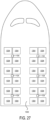
- FIG. 27 depicts an aircraft environment in which UV light-emitting modules 104 are installed above passenger seats 1004 in the cabin 1000 of the aircraft.
- one or more UV light-emitting modules 104 may be utilized in a portable assembly, such as a wand, that is configured to be held by a user.
- a portable assembly is also configured to be removably mounted to a support structure, such as a wall.
- the UV light-emitting modules 104 are positioned to emit the UV light towards one or more components within the lavatory 102 for disinfecting and/or sanitizing the components.
- the one or more components include a sink 112 and a toilet 110.
- the UV light-emitting modules 104 are positioned to emit UV light towards different components 108.
- the first UV light-emitting module104a is positioned to emit UV light towards the toilet 110 including a flush actuator 114 (e.g., lever, button, etc.) of the toilet 110.
- the second UV light-emitting module 104b is positioned to emit UV light towards the sink 112 and the surrounding region, such as portions of the faucet 116 and countertop 118.
- the third UV light-emitting module 104c is positioned to emit UV light towards the door (not shown) used to enter and exit the lavatory 102.
- two or more UV light-emitting modules 104 are positioned to emit UV light towards a common component. In some examples, two or more UV light-emitting modules 104 are physically adjacent and/or mechanically coupled to one another.
- the power supply module 106 is electrically connected to the UV light-emitting modules 104 to provide power to the modules.
- the power supply module 106 includes processing and/or power modulation circuitry within an enclosure or housing.
- the power supply module 106 receives electrical energy from a power source, such as power distribution panel or a battery, and distributes the electrical energy among the UV light-emitting modules 104.
- the power supply module 106 is mounted within the lavatory 102 and is electrically connected to the UV light-emitting modules 104 via respective power leads 120, such as one or more electrical wires or power cables.
- respective power leads 120 such as one or more electrical wires or power cables.
- one or more of the UV light-emitting modules 104 are integrated with the power supply module 106 in a common housing.
- a UV light-emitting module 104 utilizes a small form factor to provide improved aesthetics by occupying less space.
- the smaller form factor also can enable the location of the UV light-emitting modules 104 closer to the components to be disinfected as compared to larger form factor UV light emitters.
- the smaller UV light-emitting modules 104 can be inconspicuously mounted behind or within structures that would not be possible for larger UV light emitters.
- locating the UV light-emitting modules 104 closer to components increases the radiant flux (irradiance) provided to surfaces of the components.
- a designated UV dosage can be provided to the components utilizing less energy and/or in a shorter length of time as compared to the same dosage applied by larger UV light-emitting modules.
- Figure 2 illustrates a schematic block diagram of the system 100 according to an example of the present disclosure.
- the power supply module 106 receives electrical energy from an external power source 202 that is separate and discrete from the power supply module 106.
- the power source 202 is a vehicle electrical system onboard a vehicle or an electrical system of a building or facility.
- the power source 202 is a battery, a generator, or the like.
- the power supply module 106 is electrically connected to the external power source 202 via a power conditioning circuit 204 and power cables 206 and 208.
- the power conditioning circuit 204 includes one or more rectifiers, power factor correction circuits, and/or capacitors for electromagnetic interference filtering.
- the power conditioning circuit 204 is integrated with the power supply module 106 in a common enclosure, such as a housing of the power supply module.
- the power supply module 106 receives electrical energy from the power conditioning circuit 204 and controls distribution of the electrical energy among the UV light-emitting modules 104.
- the power conditioning circuit 204 receives alternating current (AC) electrical energy from the external power source 202 and converts the AC electrical energy to DC electrical energy.
- AC alternating current
- This DC electrical energy is supplied to the power supply module 106, which converts the DC electrical energy to AC electrical energy and supplies the AC to the UV light-emitting modules 104 to power the generation of UV light as described in more detail below.
- the power supply module 106 also controls one or more operations of the UV light-emitting modules 104, such as activating and deactivating the modules, and modulating the power output of the modules.
- UV light-emitting modules of the present disclosure utilize one or more cooling features that enable the modules to operate at higher power and provide correspondingly higher UV irradiation than prior UV emitters. Additionally and in some examples described below, multiple modules are enclosed in a housing that includes one or more cooling fans to circulate air through the module(s).
- UV light-emitting module 300 one example of a UV light-emitting module 300 according to the present disclosure is illustrated.
- the UV light-emitting modules 104 described above may take the form of UV light-emitting module 300 shown in FIGS. 3-5 or one of the other examples of UV light-emitting modules described further below.
- the UV light-emitting module 300 and the other examples of UV light-emitting modules described herein can be utilized in a UV disinfecting system, such as system 100, and/or as standalone devices.
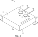
- the UV light-emitting module 300 comprises an enclosure 304 that includes a rear wall 308 and a face plate 312 spaced from the rear wall 308.
- the face plate 312 includes a light-transmitting aperture 316 through which UV light from one or more UV light emitters within the enclosure is transmitted.
- the UV light-emitting module 300 utilizes four UV light emitters 320. In other examples, fewer or more than four UV light emitters may be utilized in UV light-emitting modules according to the present disclosure.
- the UV light emitters 320 can be excimer lamps that utilize a krypton-chlorine (Kr-Cl) gas mixture provided in the lamp bulb. Such excimer lamps emit UV light having a wavelength of 222 nm that can disinfect and sanitize component surfaces via localized anti-viral and antimicrobial effects. Further, 222 nm UV light can disinfect and sanitize surfaces without skin damaging effects associated with conventional germicidal ultraviolet (UV) exposure. In other examples, the UV light-emitting module 300 can utilized other types of UV emitters and UV lamps. Additionally and as described in more detail below, the UV light emitters 320 are seated in one or more UV light emitter supports within the enclosure 304.
- Kr-Cl krypton-chlorine
- a low pass filter 324 is located adjacent to the light-transmitting aperture 316 of the face plate 312.
- the low pass filter 324 can be used to remove or filter out substantially all light emissions generated by the UV light emitters 320 except for 222 nm wavelength ultraviolet light.
- the enclosure 304 has a rectangular shape formed by a first sidewall 330, second sidewall 334, third sidewall 338 and fourth sidewall 342.
- Each of the sidewalls extends between the rear wall 308 and the face plate 312.
- other enclosures of the present disclosure can have other shapes and form factors, such as a circular enclosure formed by a single circular sidewall.
- the enclosure 304 utilizes one or more cooling features that enable the module 300 to operate at higher power and provide correspondingly higher UV irradiation than prior UV emitters.
- the enclosure includes cooling features in the form of a sidewall ventilation opening 348 in first sidewall 330 and a rear wall ventilation opening 352 in the rear wall 308. In this manner, these ventilation openings enable airflow through the interior of the enclosure 304 and over the surfaces of the UV light emitters 320, to thereby cool the emitters by transferring heat generated by emitters from the enclosure.
- ventilation openings can be provided in other locations on the enclosure 304.
- the rear wall 308 and the first sidewall 330, second sidewall 334, third sidewall 338 and fourth sidewall 342 of the enclosure 304 are fabricated from a plastic material.
- the rear wall 308 and the first sidewall 330, second sidewall 334, third sidewall 338 and fourth sidewall 342 are fabricated from aluminum.
- the aluminum walls have a higher thermal conductivity than plastic, thereby providing greater heat transfer and dissipation from the UV light emitters 320 through the walls of the enclosure 304.
- the face plate 312 is fabricated from plastic. In other examples, the face plate 312 is also fabricated from aluminum to provide even greater heat transfer from within the enclosure 304.
- the UV light emitters 320 are seated in V-shaped grooves in a first UV light emitter support 322 and a second UV light emitter support 323 that extend parallel to one another.
- the UV light emitter supports 322, 323 are also fabricated from a conductive material, such as aluminum. In this manner and by seating the UV light emitters 320 in the supports, the emitters are electrically coupled to the supports.
- the UV light emitter supports 322, 323 are fabricated from a fluoropolymer and the UV light emitters 320 are electrically coupled to a power source via lead wires.
- a thermally conductive and electrically insulating separator 350 is positioned between the UV light emitter supports and the rear wall to electrically isolate the UV light emitter supports from the aluminum rear wall.
- the thermally conductive and electrically insulating separator 350 has a thermal conductivity of approximately 15 international British thermal unit per hour per square foot per degree Fahrenheit (BTU)/(°F Hr. Ft. 2 ) or (85,174 W/m 2 K) higher.
- the thermally conductive and electrically insulating separator 350 is fabricated from an alumina-based ceramic.
- the thermally conductive and electrically insulating separator 350 can be fabricated from Cotronics Durapot 810 castable ceramic cement, manufactured by Cotronics Corporation. Accordingly, in these examples the higher thermal conductivity of separator 350 further facilitates heat transfer from the enclosure to cool the UV light emitters 320.
- the first UV light emitter support 322 and second UV light emitter support 323 receive power via first electrical conductor 354 and second electrical conductor 356, respectively, that extend through the rear wall 308 into the UV light emitter supports.
- first electrical conductor 354 and second electrical conductor 356 also extend through apertures in the thermally conductive and electrically insulating separator 350.
- the first electrical conductor 354 and second electrical conductor 356 are electrically coupled to a power source via wires 360, 362.
- the power source is the power supply module 106 of system 100.
- the first electrical conductor 354 is electrically insulated from the rear wall 308 by a first electrically insulating bushing 361 between the first electrical conductor and the rear wall.
- the second electrical conductor 356 is electrically insulated from the rear wall 308 by a second electrically insulating bushing 363 between the first electrical conductor and the rear wall.
- the enclosure 304 includes attachment tabs 366 and 368 configured to receive a fastener for securing the enclosure to a surface.
- the first UV light emitter support 322 comprises a plurality of first triangular-shaped internal support surfaces 372 that are facing corresponding second triangular-shaped internal support surfaces 376 of the second UV light emitter support 323.
- each of the first triangular-shaped internal support surfaces 372 includes first radiused edges 380 along one or both upwardly extending sides and the apex.
- each of the second triangular-shaped internal support surfaces 376 includes second radiused edges 384 along one or both upwardly extending sides and the apex. In some examples, these radiused edges can have a radius of between approximately 0.05 inches (1.27 millimeters) and 0.10 inches. 2.54 millimeters).
- the UV light-emitting module 300 also includes a circuit board 400 comprising a UV LED that is configured to pre-ionize gas in the UV light emitters 320.
- a circuit board 400 comprising a UV LED that is configured to pre-ionize gas in the UV light emitters 320.
- the first sidewall 330 is a conductive material, such as aluminum
- an electrical insulator panel 404 is provided between the circuit board 400 and the first sidewall 330.
- one or more ventilation openings can be provided in two or more of the four sidewalls of the enclosure 304.
- the enclosure includes a first sidewall ventilation opening 348 in first sidewall 330 and a second sidewall ventilation opening 349 in third sidewall 338.
- the rear wall 308 can include two or more ventilation openings.
- the enclosure includes a first rear wall ventilation opening 352 and a second rear wall ventilation opening 353 in rear wall 308. Additionally, in this example a sidewall ventilation opening 348 in third sidewall 338 is provided.
- ventilation openings of any suitable combination, quantity, size and/or shape can be provided in one or more of the sidewalls and in the rear wall 308.
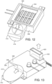
- the module 300 may include a cooling fan configured to deliver forced air through either a sidewall ventilation opening or a rear wall ventilation opening.
- a cooling fan 410 is mounted to third sidewall 338 adjacent to ducting 414 that directs air from the fan into ventilation opening 349 in third sidewall 338.
- the air passes over and through the UV light emitters 320 and other components inside the enclosure 304 and exits through rear wall ventilation opening 352 in rear wall 308.
- a fitting 420 is affixed to the rear wall ventilation opening 352 to direct the exiting airflow away from the module.
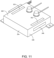
- UV light-emitting modules of the present disclosure include one or more cooling features in the form of a heat sink feature.
- the module includes a heat sink feature in the form of a plurality of fins 428 extending from the rear wall 308.
- the fins may have different sizes and shapes, such as thin elongated plates arranged adjacent to one another.
- the number and placement of the fins on the enclosure also can vary according to applications and use environments.
- heat sink fins can additionally or alternatively be located on one or more sidewalls of the enclosure.
- modules according to the present disclosure can include one or more ventilation openings and one or more heat sink features.
- the module includes the plurality of fins 428 extending from the rear wall 308, a first rear wall ventilation opening 352 and a second rear wall ventilation opening 353 in rear wall 308, and a sidewall ventilation opening 348 in third sidewall 338.
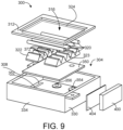
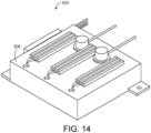
- one or more UV light-emitting modules 300 are enclosed in a housing that provides forced ventilation via at least one cooling fan that directs air into the housing and at least one housing ventilation exit opening through which the air escapes.
- a housing 500 includes a container portion 504 in which two UV light-emitting modules 300 according to the present disclosure are located. Both UV light-emitting modules 300 include a single sidewall ventilation opening 349 and a single rear wall ventilation opening to which a fitting 420 is affixed.
- the container portion 504 includes two intake cooling fans 510 configured to pull air into and pressurize the housing 500.
- Each of the cooling fans 510 are seated within and pneumatically coupled to a respective housing ventilation intake opening 512 in the housing 500.
- a bottom panel 514 of the container portion 504 includes module cutouts 520, 524 in which the two UV light-emitting modules 300 are seated.
- the light-transmitting apertures 316 in each of the modules 300 face downwardly through the cutouts 520, 524 to direct UV light downwardly from the housing 500.
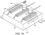
- each of the UV light-emitting modules 300 includes a sidewall ventilation opening 349 into which pressurized air within the housing 500 enters. The air passes over and through the UV light emitters 320 and other components inside the enclosures of the modules 300 and exits through a rear wall ventilation opening 352 in rear wall 308.
- fittings 420 affixed to the rear wall ventilation openings are extend through and are pneumatically coupled to respective housing ventilation exit openings 530, 534 in cover panel 538 and direct the exiting airflow from the modules through these openings and into atmosphere.
- the two housing ventilation exit openings 530, 534 are located above the module cutouts 520, 524, respectively, in bottom panel 514 and are positioned to receive and allow the fittings 420 to extend through the openings. In this manner, the housing ventilation exit openings 530, 534 allow pressurized air within the housing 500 and UV light-emitting modules 300 to escape.
- each of the UV light-emitting modules 300 within the housing 500 receives power from a common power source, such as the external power source 202 of the system 100 shown in FIG. 2 .
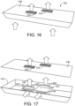
- the UV light emitter support 450 has a first side 454 and an opposing second side 456.
- each of the UV light emitters 320 seated in the UV light emitter support 450 is an elongated lamp having a first end 328 and an opposing second end 329.
- the first end 328 of each of the lamps extends beyond the first side 454 of the UV light emitter support 450, and the second end of each of the lamps extends beyond the second side 456 of the UV light emitter support.
- two or more UV light emitter supports 450 fabricated from a fluoropolymer may be combined to seat the UV light emitters 320.
- three fluoropolymer UV light emitter supports 452, 455 and 457 are placed side-by-side to form a square-shaped UV light emitter support.
- the UV light emitter supports can have different lengths and widths, and can be combined to form a variety of shapes and sizes.
- UV light emitter supports fabricated from conductive materials and from fluoropolymers may be utilized.
- the UV light emitter support 455 is fabricated from a conductive material, such as aluminum, while the UV light emitter supports 452 and 457 on either side are fabricated from a fluoropolymer.
- a thermally conductive and electrically insulating separator 350 is provided between the UV light emitter supports 452, 455 and 457 and the rear wall.
- lead wires 340 and 344 electrically couple terminals of the elongated lamps to a power source.
- an electrical conductor extends through the rear wall of the UV light emitting module into each of the aluminum UV light emitter supports to provide power to the light emitters as described above.
- first ends 328 and second ends 329 of each of the UV light emitters 320 are substantially flush with the first side 454 and the second side 456, respectively, of the UV light emitter support.
- the terminals 332 and 336 at the ends of the UV light emitters 320 are substantially flush with the first side 454 and the second side 456, respectively.
- UV light-emitting modules and related systems for disinfecting one or more components of the present disclosure can utilize any suitable combinations of features described herein, including but not limited to ventilation openings, heat sink features, and component materials.
- each of the UV light-emitting modules includes an enclosure having a rear wall with a rear wall ventilation opening and a face plate spaced from the rear wall and having a light-transmitting aperture. At least one sidewall extends between the rear wall and the face plate, with the at least one sidewall having a sidewall ventilation opening.
- Each module further includes at least one UV light emitter within the enclosure.
- the housing includes at least one cooling fan configured to direct air into the housing and at least a first housing ventilation exit opening and a second housing ventilation exit opening.
- method 1300 includes the step of affixing the plurality of UV light-emitting modules inside the housing.
- the method 1300 includes the step of pneumatically coupling the first housing ventilation exit opening to the rear wall ventilation opening of a first UV light-emitting module of the plurality of UV light-emitting modules.
- the method 1300 includes pneumatically coupling the second housing ventilation exit opening to the rear wall ventilation opening of a second UV light-emitting module of the plurality of UV light-emitting modules.
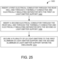
- FIG. 25 a method 1400 of assembling an ultraviolet (UV) light-emitting module for disinfecting one or more components is illustrated.
- the method 1400 is performed using an enclosure including a rear wall and a face plate spaced from the rear wall that includes a light-transmitting aperture.
- the enclosure also includes four sidewall that extend between the rear wall and the face plate.
- the method 1400 is also performed using a first UV light emitter support and a second UV light emitter support, and at least one cooling feature selected from (1) a sidewall ventilation opening in the at least one sidewall and (2) a heat sink feature extending from the rear wall.
- the method 1400 includes the step of inserting a first electrical conductor through the rear wall and through a thermally conductive and electrically insulating separator into the first UV light emitter support.
- the method 1400 includes the step of inserting a second electrical conductor through the rear wall and through the thermally conductive and electrically insulating separator into the second UV light emitter support.
- the method 1400 includes the step of securing a plurality of UV light emitters to the first aluminum UV light emitter support and the second aluminum UV light emitter support within the enclosure.
- FIG. 26 a method 1500 of assembling an ultraviolet (UV) light-emitting module for disinfecting one or more components is illustrated.
- the method 1500 is performed using an enclosure that includes a rear wall and a face plate spaced from the rear wall and having a light-transmitting aperture, and four sidewalls extending between the rear wall and the face plate, at least one UV light emitter support fabricated from a fluoropolymer, at least one cooling feature selected from (1) a sidewall ventilation opening in the at least one sidewall and (2) a heat sink feature extending from the rear wall, and at least one UV light emitter comprising an elongated lamp that comprises a first end having a first terminal and an opposing second end having a second terminal.
- UV ultraviolet
- the method 1500 includes the step of seating the elongated lamp in the at least one fluoropolymer UV light emitter support within the enclosure.
- the method 1500 includes the step of securing a first lead wire to the first terminal of the elongated lamp.
- the method 1400 includes the step of securing a second lead wire to the second terminal of the elongated lamp.
- the at least one cooling fan may be pneumatically coupled to a housing ventilation intake opening in the housing.
Landscapes
- Health & Medical Sciences (AREA)
- Engineering & Computer Science (AREA)
- Public Health (AREA)
- Epidemiology (AREA)
- Life Sciences & Earth Sciences (AREA)
- General Health & Medical Sciences (AREA)
- Veterinary Medicine (AREA)
- Animal Behavior & Ethology (AREA)
- Chemical & Material Sciences (AREA)
- Combustion & Propulsion (AREA)
- Mechanical Engineering (AREA)
- General Engineering & Computer Science (AREA)
- Hydrology & Water Resources (AREA)
- Water Supply & Treatment (AREA)
- Apparatus For Disinfection Or Sterilisation (AREA)
- Led Device Packages (AREA)
Claims (15)
- Ultraviolettes (UV) Licht emittierendes Modul (300) zum Desinfizieren einer oder mehrerer Komponenten, wobei das UV-Licht emittierende Modul aufweist:ein Gehäuse (304) mit:einer Rückwand (308);einer Stirnplatte (312), die von der Rückwand beabstandet ist und eine lichtdurchlässige Öffnung aufweist; undmindestens einer Seitenwand (330, 334, 338, 342), die sich zwischen der Rückwand und der Stirnplatte erstreckt; undmindestens einen UV-Licht-Emitter (320) in dem Gehäuse,wobei eine Belüftungsöffnung (348, 349, 352, 353) in einer oder mehreren Wänden, ausgewählt aus (1) der Rückwand und (2) der mindestens einen Seitenwand, angeordnet ist;dadurch gekennzeichnet, dassdas Ultraviolett (UV) Licht emittierende Modul (300) drei oder mehr UV-Licht-Emitter-Träger (452, 455, 457) in dem Gehäuse (304) aufweist, wobei die drei oder mehr UV-Licht-Emitter-Träger (452, 455, 457) einen UV-Licht-Emitter-Träger (455) aus Aluminium aufweisen, der zwischen einem ersten UV-Licht-Emitter-Träger (452, 457) aus Fluorpolymer und einem zweiten UV-Licht-Emitter-Träger (452, 457) aus Fluorpolymer angeordnet ist.
- UV-Licht emittierendes Modul nach Anspruch 1, wobei die Rückwand (308) und die mindestens eine Seitenwand (330, 334, 338, 342) aus Aluminium sind.
- UV-Licht emittierendes Modul nach einem der Ansprüche 1 bis 2, wobei die Stirnplatte (312) aus Aluminium ist.
- UV-Licht emittierendes Modul nach einem der Ansprüche 1 bis 3, wobei mehrere Belüftungsöffnungen (352, 353) in der Rückwand (308) angeordnet sind.
- UV-Licht emittierendes Modul nach einem der Ansprüche 1 bis 4, ferner aufweisend ein Kühlgebläse (410, 510), das konfiguriert ist, um durch die Belüftungsöffnung in der Rückwand (308) und/oder in der mindestens einen Seitenwand (330, 334, 338, 342) Luft zuzuführen.
- UV-Licht emittierendes Modul nach einem der Ansprüche 1 bis 5, wobei die mindestens eine Seitenwand (330, 334, 338, 342) vier Seitenwände aufweist, und zwei oder mehr der vier Seitenwände eine Seitenwand-Belüftungsöffnung (348, 349) aufweisen.
- UV-Licht emittierendes Modul nach einem der Ansprüche 1 bis 6, ferner aufweisend mehrere Rippen (428), die sich von der Rückwand (308) aus erstrecken.
- UV-Licht emittierendes Modul nach einem der Ansprüche 1 bis 7, wobei der mindestens eine UV-Lichtemitter (320) konfiguriert ist, um UV-Licht einer Wellenlänge von 222 Nanometer (nm) zu emittieren.
- UV-Licht emittierendes Modul nach einem der Ansprüche 1 bis 8, ferner aufweisend ein Tiefpassfilter (324) angrenzend an die lichtdurchlässige Öffnung der Stirnplatte (312).
- UV-Licht emittierendes Modul nach einem der Ansprüche 1 bis 9, wobei der mindestens eine UV-Lichtemitter (320) eine Excimer-Lampe aufweist, das UV-Licht emittierende Modul ferner eine Leiterplatte (400) mit einer UV-Licht emittierenden Diode (LED) aufweist, die konfiguriert ist, um Gas in der Excimer-Lampe vorab zu ionisieren.
- UV-Licht emittierendes Modul nach einem der Ansprüche 1 bis 10, wobei das Fluorpolymer Polytetrafluorethylen (PTFE) ist.
- System (100) zum Desinfizieren einer oder mehrerer Komponenten, wobei das System aufweist:mehrere Ultraviolett (UV) Licht emittierende Module (300) nach Anspruch 1; undeine Einhausung (500), die die mehreren UV-Licht emittierenden Module enthält, wobei die Einhausung mindestens ein Kühlgebläse (410, 510), das Luft in die Einhausung lenkt, und mindestens eine Einhausung-Luftaustrittsöffnung (530, 534), durch die Luft entweicht, aufweist.
- System nach Anspruch 12, wobei jedes der UV-Licht emittierenden Module Energie aus einer gemeinsamen Energiequelle (202) empfängt.
- System nach einem der Ansprüche 12 bis 13, wobei jedes der UV-Licht emittierenden Module eine Seitenwand-Belüftungsöffnung (348, 349) in der mindestens einen Seitenwand und eine Rückwand-Belüftungsöffnung (352, 353) in der Rückwand (308) aufweist, und jede Einhausung-Luftaustrittsöffnung (530, 534) pneumatisch mit der jeweiligen Rückwand-Belüftungsöffnung (352, 353) gekoppelt ist.
- Verfahren (1500) zum Zusammenbauen eines ultraviolettes (UV) Licht emittierenden Moduls (300) zum Desinfizieren einer oder mehrerer Komponenten, wobei das Verfahren unter Verwendung eines Gehäuses (304) durchgeführt wird, das aufweist: eine Rückwand (308) und eine Stirnplatte (312), die von der Rückwand beabstandet ist und eine lichtdurchlässige Öffnung (316) aufweist, und vier Seitenwände (330, 334, 338, 342), die sich zwischen der Rückwand und der Stirnplatte erstrecken, drei oder mehr UV-Licht-Emitter-Träger (452, 455, 457) in dem Gehäuse (304), wobei die drei oder mehr UV-Licht-Emitter-Träger (452, 455, 457) einen UV-Licht-Emitter-Träger (455) aus Aluminium aufweisen, der zwischen einem ersten UV-Licht-Emitter-Träger (452, 457) aus Fluorpolymer und einem zweiten UV-Licht-Emitter-Träger (452, 457) aus Fluorpolymer angeordnet ist, mindestens ein Kühlmerkmal, ausgewählt aus (1) einer Seitenwand-Belüftungsöffnung (348, 349) in mindestens einer Seitenwand und (2) einem sich von der Rückwand aus erstreckenden Wärmesenke-Merkmal (428), und wobei mindestens ein UV-Licht-Emitter eine längliche Lampe aufweist, die ein erstes Ende (328) mit einem ersten Anschluss (332) und ein gegenüberliegendes zweites Ende (329) mit einem zweiten Anschluss (336) aufweist, wobei das Verfahren aufweist:Einsetzen (1502) der länglichen Lampe in den mindestens einen aus Fluorpolymer hergestellten UV-Licht-Emitter-Träger in dem Gehäuse;Verbinden (1506) eines ersten Leitungsdrahts (340) mit dem ersten Anschluss der länglichen Lampe; undVerbinden (1510) eines zweiten Leitungsdrahts (344) mit dem zweiten Anschluss der länglichen Lampe.
Applications Claiming Priority (3)
| Application Number | Priority Date | Filing Date | Title |
|---|---|---|---|
| US202063124341P | 2020-12-11 | 2020-12-11 | |
| US202163154239P | 2021-02-26 | 2021-02-26 | |
| US17/452,559 US12165864B2 (en) | 2020-12-11 | 2021-10-27 | Ultraviolet light-emitting module and disinfecting system |
Publications (3)
| Publication Number | Publication Date |
|---|---|
| EP4011398A2 EP4011398A2 (de) | 2022-06-15 |
| EP4011398A3 EP4011398A3 (de) | 2022-10-12 |
| EP4011398B1 true EP4011398B1 (de) | 2024-08-07 |
Family
ID=78806329
Family Applications (1)
| Application Number | Title | Priority Date | Filing Date |
|---|---|---|---|
| EP21210726.2A Active EP4011398B1 (de) | 2020-12-11 | 2021-11-26 | Ultraviolettes licht-emittierendes modul und desinfektionssystem |
Country Status (4)
| Country | Link |
|---|---|
| US (1) | US12165864B2 (de) |
| EP (1) | EP4011398B1 (de) |
| JP (1) | JP7827440B2 (de) |
| CN (1) | CN114617990A (de) |
Families Citing this family (1)
| Publication number | Priority date | Publication date | Assignee | Title |
|---|---|---|---|---|
| US20250145295A1 (en) * | 2023-11-02 | 2025-05-08 | B/E Aerospace, Inc. | Infant/toddler restraint system for lavatory |
Family Cites Families (71)
| Publication number | Priority date | Publication date | Assignee | Title |
|---|---|---|---|---|
| US5216251A (en) * | 1991-10-18 | 1993-06-01 | Matschke Arthur L | Apparatus and method for a bio-conditioning germicidal dryer |
| JP3646820B2 (ja) | 1996-01-30 | 2005-05-11 | 岩崎電気株式会社 | 紫外線殺菌装置 |
| US6144175A (en) | 1997-11-05 | 2000-11-07 | Parra; Jorge M. | Low-voltage ballast-free energy-efficient ultraviolet material treatment and purification system and method |
| JP2000283840A (ja) | 1999-03-31 | 2000-10-13 | Minolta Co Ltd | 測光機器 |
| US6656424B1 (en) | 2000-02-18 | 2003-12-02 | Uvas, Llc | Ultraviolet area sterilizer and method of area sterilization using ultraviolet radiation |
| US6880351B2 (en) | 2001-09-05 | 2005-04-19 | Be Intellectual Property, Inc. | Liquid galley refrigeration system for aircraft |
| ITFI20010172A1 (it) | 2001-09-17 | 2003-03-17 | El En Spa | Apparecchiatura con lampada a spettro nell'ultravioletto,per il trattamento della psoriasi |
| US7875247B2 (en) | 2002-11-27 | 2011-01-25 | Novatron, Inc. | UV flux multiplication system for sterilizing air, medical devices and other materials |
| US7595723B2 (en) | 2005-11-14 | 2009-09-29 | Edwards Lifesciences Corporation | Wireless communication protocol for a medical sensor system |
| US8941078B2 (en) | 2006-03-29 | 2015-01-27 | Jansyl Industries, Llc | Infant stimulation and environment sterilizing device |
| GB2451873B (en) | 2007-08-15 | 2009-08-12 | Jenact Ltd | UV irradiator |
| US8581522B2 (en) | 2008-09-19 | 2013-11-12 | Mathew Inskeep | Countertop decontaminating device |
| GB2470415A (en) | 2009-05-22 | 2010-11-24 | Steritrox Ltd | A sterilisation and decontamination device |
| US8662705B2 (en) | 2010-03-30 | 2014-03-04 | Virwall Systems, Inc. | Flexible ultraviolet LED sanitizing apparatus |
| US20120168641A1 (en) | 2010-09-08 | 2012-07-05 | Lizotte Todd E | Uv ptfe diffuser technology |
| US8698100B2 (en) | 2011-03-23 | 2014-04-15 | Dean Schumacher | System and apparatus for sanitizing a door opening device or other point of contact |
| BR112013026529A2 (pt) | 2011-04-15 | 2016-09-20 | Samuel Richard Trapani | método e sistema de esterilização de ambiente |
| US20120305787A1 (en) | 2011-06-04 | 2012-12-06 | Brian Roy Henson | Apparatus and Method for Area Disinfection Using Ultraviolet Light |
| US9919068B2 (en) | 2012-08-28 | 2018-03-20 | Sensor Electronic Technology, Inc. | Storage device including ultraviolet illumination |
| JP2016500284A (ja) | 2012-12-06 | 2016-01-12 | ゼネックス・ディスインフェクション・サービシィズ・エルエルシイ | 殺菌デバイスの動作パラメータ及び消毒スケジュールを決定するシステム、並びにレンズシステムを含む殺菌ランプ装置 |
| US8907304B2 (en) | 2013-02-27 | 2014-12-09 | Arthur Kreitenberg | Ultraviolet autonomous trolley for sanitizing aircraft |
| US8791441B1 (en) | 2013-08-27 | 2014-07-29 | George Jay Lichtblau | Ultraviolet radiation system |
| WO2015028334A1 (en) | 2013-08-29 | 2015-03-05 | Koninklijke Philips N.V. | A light emitting device and a method for manufacturing a light emitting device |
| WO2015031785A1 (en) * | 2013-08-30 | 2015-03-05 | American Air & Water, Inc. | Ultraviolet disinfection lighting system |
| DE112014004109B4 (de) * | 2013-09-06 | 2021-05-20 | Sensor Electronic Technology Inc. | Diffuse Ultraviolettbeleuchtung |
| KR20150045628A (ko) | 2013-10-21 | 2015-04-29 | 서울바이오시스 주식회사 | 살충 및 살균 기능을 포함하는 좌석 시스템 |
| DE102014101935B4 (de) * | 2014-02-17 | 2018-05-30 | Heraeus Noblelight Gmbh | Betriebsverfahren für eine Bestrahlungsvorrichtung |
| WO2016079658A1 (en) | 2014-11-18 | 2016-05-26 | Industries Yifei Wang Inc. | Led module, methods of manufacturing same and luminaire integrating same |
| US9623133B2 (en) | 2015-01-30 | 2017-04-18 | The Boeing Company | Lavatory disinfection system |
| US9457121B1 (en) | 2015-03-17 | 2016-10-04 | Matthew Phillip Davis | Ultraviolate light sterilization apparatus |
| US9987383B2 (en) | 2015-05-07 | 2018-06-05 | Sensor Electronic Technology, Inc. | Medical device treatment |
| WO2016210399A2 (en) | 2015-06-25 | 2016-12-29 | Daylight Medical, Inc. | Decontamination system and decontamination unit housing equipped with remote control |
| CN113069570B (zh) * | 2015-06-26 | 2023-07-14 | 首尔伟傲世有限公司 | 便携式杀菌装置 |
| JP6256813B2 (ja) * | 2015-08-18 | 2018-01-10 | ウシオ電機株式会社 | 光線治療器 |
| RU2719338C2 (ru) | 2016-01-07 | 2020-04-17 | Майкл МЕЙ | Модульные соединители для осветительного устройства в сборе |
| JP2018007768A (ja) | 2016-07-12 | 2018-01-18 | オルガノ株式会社 | 流体処理装置および流体処理方法 |
| CN106049005B (zh) | 2016-07-19 | 2018-12-04 | 湖南城市学院 | 一种杀菌带红外遥控的袜子速干机 |
| US10918748B2 (en) | 2016-09-08 | 2021-02-16 | The Boeing Company | Deployable ultraviolet light sanitizing systems and methods |
| JP6800678B2 (ja) | 2016-09-29 | 2020-12-16 | 株式会社オーク製作所 | 放電ランプおよび放電ランプ装置 |
| JP6862803B2 (ja) | 2016-12-01 | 2021-04-21 | 岩崎電気株式会社 | 照射装置 |
| US10910210B2 (en) | 2017-01-10 | 2021-02-02 | Ushio Denki Kabushiki Kaisha | Ultraviolet sterilizer |
| JP2018167166A (ja) | 2017-03-29 | 2018-11-01 | ウシオ電機株式会社 | 光照射装置、及びこれを備えた光硬化装置 |
| US10994040B2 (en) | 2017-05-26 | 2021-05-04 | Sensor Electronic Technology, Inc. | Surface treatment with ultraviolet light |
| CN107802872A (zh) | 2017-11-21 | 2018-03-16 | 无锡协联信息技术有限公司 | 一种办公设备消毒装置 |
| JP7314138B2 (ja) | 2017-12-11 | 2023-07-25 | ダブリュ.エル.ゴア アンド アソシエイツ,インコーポレイティド | 可撓性紫外光生成シート及びシステムを製造するための方法 |
| US10427792B1 (en) | 2018-04-01 | 2019-10-01 | The Boeing Company | Vehicle with a simulated window feature |
| JP6994687B2 (ja) | 2018-08-08 | 2022-01-14 | 株式会社Uskテクノロジー | 流体殺菌装置 |
| WO2020040990A1 (en) | 2018-08-21 | 2020-02-27 | Gentex Corporation | Disinfection system |
| CN209060072U (zh) | 2018-09-10 | 2019-07-05 | 深圳市开颜医疗器械有限公司 | 一种消毒照明系统 |
| US12194168B2 (en) | 2018-12-19 | 2025-01-14 | Vyv, Inc. | Lighting and dissipation device |
| CN111744026B (zh) | 2019-03-29 | 2023-08-18 | 东芝照明技术株式会社 | 紫外线放射装置以及照明装置 |
| CN211204004U (zh) | 2019-11-21 | 2020-08-07 | 深圳市隆兴达科技有限公司 | 一种照明抑菌一体化灯具 |
| US20210361794A1 (en) | 2020-02-24 | 2021-11-25 | Stephen A. Yencho | Portable Infection Prevention Systems |
| US11957810B2 (en) | 2020-05-08 | 2024-04-16 | The Boeing Company | Ultraviolet light sanitizing pacing systems and methods |
| US20210346540A1 (en) | 2020-05-08 | 2021-11-11 | The Boeing Company | Portable sanitizing system having a backpack assembly coupled to a wand assembly |
| US20210386883A1 (en) | 2020-06-11 | 2021-12-16 | The Boeing Company | Ultraviolet sanitizing pacing systems and methods |
| US12576172B2 (en) | 2020-05-08 | 2026-03-17 | The Boeing Company | Ultraviolet light sanitizing cart having a wand assembly |
| US11382993B2 (en) | 2020-05-20 | 2022-07-12 | The Boeing Company | Portable sanitizing systems and methods with range guidance |
| US11679169B2 (en) | 2020-06-11 | 2023-06-20 | The Boeing Company | Systems and methods for providing power to ultraviolet lamps of sanitizing systems |
| US11617810B2 (en) | 2020-06-11 | 2023-04-04 | The Boeing Company | Systems and methods for providing power to ultraviolet lamps of sanitizing systems |
| US11782197B2 (en) | 2020-06-23 | 2023-10-10 | The Boeing Company | Ultraviolet light wavelength selective filter |
| US11793896B2 (en) | 2020-07-22 | 2023-10-24 | The Boeing Company | Portable sanitizing systems and methods |
| US20220023459A1 (en) | 2020-07-23 | 2022-01-27 | The Boeing Company | Ultraviolet light sanitizing cart |
| US12233178B2 (en) | 2020-07-23 | 2025-02-25 | The Boeing Company | Systems and methods of verifying effective motion of a wand assembly of an ultraviolet (UV) light sanitizing system |
| JP6947261B1 (ja) | 2020-09-01 | 2021-10-13 | ウシオ電機株式会社 | 紫外線照射装置 |
| US20220111087A1 (en) | 2020-10-14 | 2022-04-14 | The Boeing Company | Ultraviolet light sanitizing systems and methods |
| US11933477B2 (en) | 2020-10-14 | 2024-03-19 | The Boeing Company | Systems and methods for aligning ultraviolet lamps |
| US12076452B2 (en) | 2020-10-14 | 2024-09-03 | The Boeing Company | Modulated ultraviolet light sanitizing system and method |
| US20220111096A1 (en) | 2020-10-14 | 2022-04-14 | The Boeing Company | Ultraviolet light sanitizing systems and methods |
| US20220133925A1 (en) * | 2020-11-03 | 2022-05-05 | Wholetek Inc. | Sanitizing apparatus |
| EP4011400B1 (de) | 2020-12-11 | 2025-07-23 | The Boeing Company | System und verfahren zur desinfektion mit ultraviolettem licht mit verteilter energie |
-
2021
- 2021-10-27 US US17/452,559 patent/US12165864B2/en active Active
- 2021-11-25 JP JP2021191190A patent/JP7827440B2/ja active Active
- 2021-11-26 EP EP21210726.2A patent/EP4011398B1/de active Active
- 2021-12-10 CN CN202111508513.XA patent/CN114617990A/zh active Pending
Also Published As
| Publication number | Publication date |
|---|---|
| EP4011398A2 (de) | 2022-06-15 |
| US12165864B2 (en) | 2024-12-10 |
| US20220189759A1 (en) | 2022-06-16 |
| CN114617990A (zh) | 2022-06-14 |
| JP2022093285A (ja) | 2022-06-23 |
| JP7827440B2 (ja) | 2026-03-10 |
| EP4011398A3 (de) | 2022-10-12 |
Similar Documents
| Publication | Publication Date | Title |
|---|---|---|
| EP4011402B1 (de) | Ultraviolettes licht-emittierendes modul und desinfektionssystem | |
| EP4011399B1 (de) | Ultraviolettes licht-emittierendes modul und desinfektionssystem | |
| JP5371990B2 (ja) | 発光装置及び発光装置を冷却する方法 | |
| EP4023254B1 (de) | Ultraviolettlicht-emittierendes modul und desinfektionssystem | |
| US12246103B2 (en) | Ultraviolet light sanitizing system and method with distributed power | |
| KR20100130544A (ko) | 팬 장착 제균 조명장치 | |
| EP4011398B1 (de) | Ultraviolettes licht-emittierendes modul und desinfektionssystem | |
| US20250339574A1 (en) | Ultraviolet light-emitting assembly | |
| US12582739B2 (en) | UVC air disinfection device with LED thermal management system | |
| US20230059472A1 (en) | Air cleaning apparatus and methods of providing and using the same | |
| EP3941535A1 (de) | Uvc-erweiterte elektromagnetische strahlung mit reflektierenden schirmen und matten | |
| US20240033393A1 (en) | Far-uvc emitter | |
| JP2022057575A (ja) | 紫外線照射装置 |
Legal Events
| Date | Code | Title | Description |
|---|---|---|---|
| PUAI | Public reference made under article 153(3) epc to a published international application that has entered the european phase |
Free format text: ORIGINAL CODE: 0009012 |
|
| STAA | Information on the status of an ep patent application or granted ep patent |
Free format text: STATUS: THE APPLICATION HAS BEEN PUBLISHED |
|
| AK | Designated contracting states |
Kind code of ref document: A2 Designated state(s): AL AT BE BG CH CY CZ DE DK EE ES FI FR GB GR HR HU IE IS IT LI LT LU LV MC MK MT NL NO PL PT RO RS SE SI SK SM TR |
|
| PUAL | Search report despatched |
Free format text: ORIGINAL CODE: 0009013 |
|
| AK | Designated contracting states |
Kind code of ref document: A3 Designated state(s): AL AT BE BG CH CY CZ DE DK EE ES FI FR GB GR HR HU IE IS IT LI LT LU LV MC MK MT NL NO PL PT RO RS SE SI SK SM TR |
|
| RIC1 | Information provided on ipc code assigned before grant |
Ipc: H01J 65/04 20060101ALI20220902BHEP Ipc: H01J 61/54 20060101ALI20220902BHEP Ipc: G02B 5/20 20060101ALI20220902BHEP Ipc: F21V 29/00 20150101ALI20220902BHEP Ipc: F24F 8/22 20210101ALI20220902BHEP Ipc: F21V 7/00 20060101ALI20220902BHEP Ipc: F21K 9/00 20160101ALI20220902BHEP Ipc: E03D 9/00 20060101ALI20220902BHEP Ipc: B64C 39/00 20060101ALI20220902BHEP Ipc: B08B 7/00 20060101ALI20220902BHEP Ipc: A61L 2/10 20060101ALI20220902BHEP Ipc: A61L 2/00 20060101AFI20220902BHEP |
|
| RAP3 | Party data changed (applicant data changed or rights of an application transferred) |
Owner name: THE BOEING COMPANY |
|
| STAA | Information on the status of an ep patent application or granted ep patent |
Free format text: STATUS: REQUEST FOR EXAMINATION WAS MADE |
|
| 17P | Request for examination filed |
Effective date: 20230411 |
|
| RBV | Designated contracting states (corrected) |
Designated state(s): AL AT BE BG CH CY CZ DE DK EE ES FI FR GB GR HR HU IE IS IT LI LT LU LV MC MK MT NL NO PL PT RO RS SE SI SK SM TR |
|
| STAA | Information on the status of an ep patent application or granted ep patent |
Free format text: STATUS: EXAMINATION IS IN PROGRESS |
|
| 17Q | First examination report despatched |
Effective date: 20230914 |
|
| GRAP | Despatch of communication of intention to grant a patent |
Free format text: ORIGINAL CODE: EPIDOSNIGR1 |
|
| STAA | Information on the status of an ep patent application or granted ep patent |
Free format text: STATUS: GRANT OF PATENT IS INTENDED |
|
| INTG | Intention to grant announced |
Effective date: 20240319 |
|
| GRAS | Grant fee paid |
Free format text: ORIGINAL CODE: EPIDOSNIGR3 |
|
| GRAA | (expected) grant |
Free format text: ORIGINAL CODE: 0009210 |
|
| STAA | Information on the status of an ep patent application or granted ep patent |
Free format text: STATUS: THE PATENT HAS BEEN GRANTED |
|
| AK | Designated contracting states |
Kind code of ref document: B1 Designated state(s): AL AT BE BG CH CY CZ DE DK EE ES FI FR GB GR HR HU IE IS IT LI LT LU LV MC MK MT NL NO PL PT RO RS SE SI SK SM TR |
|
| P01 | Opt-out of the competence of the unified patent court (upc) registered |
Free format text: CASE NUMBER: APP_39171/2024 Effective date: 20240701 |
|
| REG | Reference to a national code |
Ref country code: GB Ref legal event code: FG4D |
|
| REG | Reference to a national code |
Ref country code: CH Ref legal event code: EP |
|
| REG | Reference to a national code |
Ref country code: IE Ref legal event code: FG4D |
|
| REG | Reference to a national code |
Ref country code: DE Ref legal event code: R096 Ref document number: 602021016762 Country of ref document: DE |
|
| REG | Reference to a national code |
Ref country code: LT Ref legal event code: MG9D |
|
| REG | Reference to a national code |
Ref country code: NL Ref legal event code: MP Effective date: 20240807 |
|
| PG25 | Lapsed in a contracting state [announced via postgrant information from national office to epo] |
Ref country code: NO Free format text: LAPSE BECAUSE OF FAILURE TO SUBMIT A TRANSLATION OF THE DESCRIPTION OR TO PAY THE FEE WITHIN THE PRESCRIBED TIME-LIMIT Effective date: 20241107 |
|
| REG | Reference to a national code |
Ref country code: AT Ref legal event code: MK05 Ref document number: 1710204 Country of ref document: AT Kind code of ref document: T Effective date: 20240807 |
|
| PG25 | Lapsed in a contracting state [announced via postgrant information from national office to epo] |
Ref country code: GR Free format text: LAPSE BECAUSE OF FAILURE TO SUBMIT A TRANSLATION OF THE DESCRIPTION OR TO PAY THE FEE WITHIN THE PRESCRIBED TIME-LIMIT Effective date: 20241108 Ref country code: NL Free format text: LAPSE BECAUSE OF FAILURE TO SUBMIT A TRANSLATION OF THE DESCRIPTION OR TO PAY THE FEE WITHIN THE PRESCRIBED TIME-LIMIT Effective date: 20240807 Ref country code: PT Free format text: LAPSE BECAUSE OF FAILURE TO SUBMIT A TRANSLATION OF THE DESCRIPTION OR TO PAY THE FEE WITHIN THE PRESCRIBED TIME-LIMIT Effective date: 20241209 Ref country code: PL Free format text: LAPSE BECAUSE OF FAILURE TO SUBMIT A TRANSLATION OF THE DESCRIPTION OR TO PAY THE FEE WITHIN THE PRESCRIBED TIME-LIMIT Effective date: 20240807 Ref country code: FI Free format text: LAPSE BECAUSE OF FAILURE TO SUBMIT A TRANSLATION OF THE DESCRIPTION OR TO PAY THE FEE WITHIN THE PRESCRIBED TIME-LIMIT Effective date: 20240807 |
|
| PG25 | Lapsed in a contracting state [announced via postgrant information from national office to epo] |
Ref country code: BG Free format text: LAPSE BECAUSE OF FAILURE TO SUBMIT A TRANSLATION OF THE DESCRIPTION OR TO PAY THE FEE WITHIN THE PRESCRIBED TIME-LIMIT Effective date: 20240807 |
|
| PG25 | Lapsed in a contracting state [announced via postgrant information from national office to epo] |
Ref country code: LV Free format text: LAPSE BECAUSE OF FAILURE TO SUBMIT A TRANSLATION OF THE DESCRIPTION OR TO PAY THE FEE WITHIN THE PRESCRIBED TIME-LIMIT Effective date: 20240807 |
|
| PG25 | Lapsed in a contracting state [announced via postgrant information from national office to epo] |
Ref country code: IS Free format text: LAPSE BECAUSE OF FAILURE TO SUBMIT A TRANSLATION OF THE DESCRIPTION OR TO PAY THE FEE WITHIN THE PRESCRIBED TIME-LIMIT Effective date: 20241207 Ref country code: AT Free format text: LAPSE BECAUSE OF FAILURE TO SUBMIT A TRANSLATION OF THE DESCRIPTION OR TO PAY THE FEE WITHIN THE PRESCRIBED TIME-LIMIT Effective date: 20240807 |
|
| PG25 | Lapsed in a contracting state [announced via postgrant information from national office to epo] |
Ref country code: HR Free format text: LAPSE BECAUSE OF FAILURE TO SUBMIT A TRANSLATION OF THE DESCRIPTION OR TO PAY THE FEE WITHIN THE PRESCRIBED TIME-LIMIT Effective date: 20240807 |
|
| PG25 | Lapsed in a contracting state [announced via postgrant information from national office to epo] |
Ref country code: RS Free format text: LAPSE BECAUSE OF FAILURE TO SUBMIT A TRANSLATION OF THE DESCRIPTION OR TO PAY THE FEE WITHIN THE PRESCRIBED TIME-LIMIT Effective date: 20241107 Ref country code: ES Free format text: LAPSE BECAUSE OF FAILURE TO SUBMIT A TRANSLATION OF THE DESCRIPTION OR TO PAY THE FEE WITHIN THE PRESCRIBED TIME-LIMIT Effective date: 20240807 |
|
| PG25 | Lapsed in a contracting state [announced via postgrant information from national office to epo] |
Ref country code: RS Free format text: LAPSE BECAUSE OF FAILURE TO SUBMIT A TRANSLATION OF THE DESCRIPTION OR TO PAY THE FEE WITHIN THE PRESCRIBED TIME-LIMIT Effective date: 20241107 Ref country code: PT Free format text: LAPSE BECAUSE OF FAILURE TO SUBMIT A TRANSLATION OF THE DESCRIPTION OR TO PAY THE FEE WITHIN THE PRESCRIBED TIME-LIMIT Effective date: 20241209 Ref country code: PL Free format text: LAPSE BECAUSE OF FAILURE TO SUBMIT A TRANSLATION OF THE DESCRIPTION OR TO PAY THE FEE WITHIN THE PRESCRIBED TIME-LIMIT Effective date: 20240807 Ref country code: NO Free format text: LAPSE BECAUSE OF FAILURE TO SUBMIT A TRANSLATION OF THE DESCRIPTION OR TO PAY THE FEE WITHIN THE PRESCRIBED TIME-LIMIT Effective date: 20241107 Ref country code: NL Free format text: LAPSE BECAUSE OF FAILURE TO SUBMIT A TRANSLATION OF THE DESCRIPTION OR TO PAY THE FEE WITHIN THE PRESCRIBED TIME-LIMIT Effective date: 20240807 Ref country code: LV Free format text: LAPSE BECAUSE OF FAILURE TO SUBMIT A TRANSLATION OF THE DESCRIPTION OR TO PAY THE FEE WITHIN THE PRESCRIBED TIME-LIMIT Effective date: 20240807 Ref country code: IS Free format text: LAPSE BECAUSE OF FAILURE TO SUBMIT A TRANSLATION OF THE DESCRIPTION OR TO PAY THE FEE WITHIN THE PRESCRIBED TIME-LIMIT Effective date: 20241207 Ref country code: HR Free format text: LAPSE BECAUSE OF FAILURE TO SUBMIT A TRANSLATION OF THE DESCRIPTION OR TO PAY THE FEE WITHIN THE PRESCRIBED TIME-LIMIT Effective date: 20240807 Ref country code: GR Free format text: LAPSE BECAUSE OF FAILURE TO SUBMIT A TRANSLATION OF THE DESCRIPTION OR TO PAY THE FEE WITHIN THE PRESCRIBED TIME-LIMIT Effective date: 20241108 Ref country code: FI Free format text: LAPSE BECAUSE OF FAILURE TO SUBMIT A TRANSLATION OF THE DESCRIPTION OR TO PAY THE FEE WITHIN THE PRESCRIBED TIME-LIMIT Effective date: 20240807 Ref country code: ES Free format text: LAPSE BECAUSE OF FAILURE TO SUBMIT A TRANSLATION OF THE DESCRIPTION OR TO PAY THE FEE WITHIN THE PRESCRIBED TIME-LIMIT Effective date: 20240807 Ref country code: BG Free format text: LAPSE BECAUSE OF FAILURE TO SUBMIT A TRANSLATION OF THE DESCRIPTION OR TO PAY THE FEE WITHIN THE PRESCRIBED TIME-LIMIT Effective date: 20240807 Ref country code: AT Free format text: LAPSE BECAUSE OF FAILURE TO SUBMIT A TRANSLATION OF THE DESCRIPTION OR TO PAY THE FEE WITHIN THE PRESCRIBED TIME-LIMIT Effective date: 20240807 |
|
| PG25 | Lapsed in a contracting state [announced via postgrant information from national office to epo] |
Ref country code: SM Free format text: LAPSE BECAUSE OF FAILURE TO SUBMIT A TRANSLATION OF THE DESCRIPTION OR TO PAY THE FEE WITHIN THE PRESCRIBED TIME-LIMIT Effective date: 20240807 Ref country code: DK Free format text: LAPSE BECAUSE OF FAILURE TO SUBMIT A TRANSLATION OF THE DESCRIPTION OR TO PAY THE FEE WITHIN THE PRESCRIBED TIME-LIMIT Effective date: 20240807 |
|
| PG25 | Lapsed in a contracting state [announced via postgrant information from national office to epo] |
Ref country code: EE Free format text: LAPSE BECAUSE OF FAILURE TO SUBMIT A TRANSLATION OF THE DESCRIPTION OR TO PAY THE FEE WITHIN THE PRESCRIBED TIME-LIMIT Effective date: 20240807 |
|
| PG25 | Lapsed in a contracting state [announced via postgrant information from national office to epo] |
Ref country code: CZ Free format text: LAPSE BECAUSE OF FAILURE TO SUBMIT A TRANSLATION OF THE DESCRIPTION OR TO PAY THE FEE WITHIN THE PRESCRIBED TIME-LIMIT Effective date: 20240807 |
|
| PG25 | Lapsed in a contracting state [announced via postgrant information from national office to epo] |
Ref country code: SK Free format text: LAPSE BECAUSE OF FAILURE TO SUBMIT A TRANSLATION OF THE DESCRIPTION OR TO PAY THE FEE WITHIN THE PRESCRIBED TIME-LIMIT Effective date: 20240807 |
|
| REG | Reference to a national code |
Ref country code: DE Ref legal event code: R097 Ref document number: 602021016762 Country of ref document: DE |
|
| PLBE | No opposition filed within time limit |
Free format text: ORIGINAL CODE: 0009261 |
|
| STAA | Information on the status of an ep patent application or granted ep patent |
Free format text: STATUS: NO OPPOSITION FILED WITHIN TIME LIMIT |
|
| REG | Reference to a national code |
Ref country code: CH Ref legal event code: PL |
|
| PG25 | Lapsed in a contracting state [announced via postgrant information from national office to epo] |
Ref country code: MC Free format text: LAPSE BECAUSE OF FAILURE TO SUBMIT A TRANSLATION OF THE DESCRIPTION OR TO PAY THE FEE WITHIN THE PRESCRIBED TIME-LIMIT Effective date: 20240807 |
|
| PG25 | Lapsed in a contracting state [announced via postgrant information from national office to epo] |
Ref country code: LU Free format text: LAPSE BECAUSE OF NON-PAYMENT OF DUE FEES Effective date: 20241126 |
|
| REG | Reference to a national code |
Ref country code: CH Ref legal event code: PL |
|
| 26N | No opposition filed |
Effective date: 20250508 |
|
| PG25 | Lapsed in a contracting state [announced via postgrant information from national office to epo] |
Ref country code: CH Free format text: LAPSE BECAUSE OF NON-PAYMENT OF DUE FEES Effective date: 20241130 |
|
| REG | Reference to a national code |
Ref country code: BE Ref legal event code: MM Effective date: 20241130 |
|
| PG25 | Lapsed in a contracting state [announced via postgrant information from national office to epo] |
Ref country code: SE Free format text: LAPSE BECAUSE OF FAILURE TO SUBMIT A TRANSLATION OF THE DESCRIPTION OR TO PAY THE FEE WITHIN THE PRESCRIBED TIME-LIMIT Effective date: 20240807 |
|
| PG25 | Lapsed in a contracting state [announced via postgrant information from national office to epo] |
Ref country code: BE Free format text: LAPSE BECAUSE OF NON-PAYMENT OF DUE FEES Effective date: 20241130 |
|
| PG25 | Lapsed in a contracting state [announced via postgrant information from national office to epo] |
Ref country code: IE Free format text: LAPSE BECAUSE OF NON-PAYMENT OF DUE FEES Effective date: 20241126 |
|
| PG25 | Lapsed in a contracting state [announced via postgrant information from national office to epo] |
Ref country code: RO Free format text: LAPSE BECAUSE OF FAILURE TO SUBMIT A TRANSLATION OF THE DESCRIPTION OR TO PAY THE FEE WITHIN THE PRESCRIBED TIME-LIMIT Effective date: 20240807 |
|
| PGFP | Annual fee paid to national office [announced via postgrant information from national office to epo] |
Ref country code: DE Payment date: 20251128 Year of fee payment: 5 |
|
| PGFP | Annual fee paid to national office [announced via postgrant information from national office to epo] |
Ref country code: GB Payment date: 20251127 Year of fee payment: 5 |
|
| PGFP | Annual fee paid to national office [announced via postgrant information from national office to epo] |
Ref country code: FR Payment date: 20251125 Year of fee payment: 5 |
|
| PG25 | Lapsed in a contracting state [announced via postgrant information from national office to epo] |
Ref country code: IT Free format text: LAPSE BECAUSE OF FAILURE TO SUBMIT A TRANSLATION OF THE DESCRIPTION OR TO PAY THE FEE WITHIN THE PRESCRIBED TIME-LIMIT Effective date: 20240807 |
|
| PG25 | Lapsed in a contracting state [announced via postgrant information from national office to epo] |
Ref country code: HU Free format text: LAPSE BECAUSE OF FAILURE TO SUBMIT A TRANSLATION OF THE DESCRIPTION OR TO PAY THE FEE WITHIN THE PRESCRIBED TIME-LIMIT; INVALID AB INITIO Effective date: 20211126 |
|
| PG25 | Lapsed in a contracting state [announced via postgrant information from national office to epo] |
Ref country code: CY Free format text: LAPSE BECAUSE OF FAILURE TO SUBMIT A TRANSLATION OF THE DESCRIPTION OR TO PAY THE FEE WITHIN THE PRESCRIBED TIME-LIMIT; INVALID AB INITIO Effective date: 20211126 |