EP4034468B1 - Druckkammer für keg mit rfid - Google Patents
Druckkammer für keg mit rfid Download PDFInfo
- Publication number
- EP4034468B1 EP4034468B1 EP20775635.4A EP20775635A EP4034468B1 EP 4034468 B1 EP4034468 B1 EP 4034468B1 EP 20775635 A EP20775635 A EP 20775635A EP 4034468 B1 EP4034468 B1 EP 4034468B1
- Authority
- EP
- European Patent Office
- Prior art keywords
- radio
- antenna
- annular
- frequency identification
- pressure chamber
- Prior art date
- Legal status (The legal status is an assumption and is not a legal conclusion. Google has not performed a legal analysis and makes no representation as to the accuracy of the status listed.)
- Active
Links
Images





Classifications
-
- B—PERFORMING OPERATIONS; TRANSPORTING
- B67—OPENING, CLOSING OR CLEANING BOTTLES, JARS OR SIMILAR CONTAINERS; LIQUID HANDLING
- B67D—DISPENSING, DELIVERING OR TRANSFERRING LIQUIDS, NOT OTHERWISE PROVIDED FOR
- B67D1/00—Apparatus or devices for dispensing beverages on draught
- B67D1/04—Apparatus utilising compressed air or other gas acting directly or indirectly on beverages in storage containers
- B67D1/0462—Squeezing collapsible or flexible beverage containers, e.g. bag-in-box containers
-
- B—PERFORMING OPERATIONS; TRANSPORTING
- B65—CONVEYING; PACKING; STORING; HANDLING THIN OR FILAMENTARY MATERIAL
- B65D—CONTAINERS FOR STORAGE OR TRANSPORT OF ARTICLES OR MATERIALS, e.g. BAGS, BARRELS, BOTTLES, BOXES, CANS, CARTONS, CRATES, DRUMS, JARS, TANKS, HOPPERS, FORWARDING CONTAINERS; ACCESSORIES, CLOSURES, OR FITTINGS THEREFOR; PACKAGING ELEMENTS; PACKAGES
- B65D7/00—Containers having bodies formed by interconnecting or uniting two or more rigid, or substantially rigid, components made wholly or mainly of metal
- B65D7/02—Containers having bodies formed by interconnecting or uniting two or more rigid, or substantially rigid, components made wholly or mainly of metal characterised by shape
- B65D7/04—Containers having bodies formed by interconnecting or uniting two or more rigid, or substantially rigid, components made wholly or mainly of metal characterised by shape of curved cross-section, e.g. cans of circular or elliptical cross-section
- B65D7/045—Casks, barrels, or drums in their entirety, e.g. beer barrels, i.e. presenting most of the following features like rolling beads, double walls, reinforcing and supporting beads for end walls
-
- B—PERFORMING OPERATIONS; TRANSPORTING
- B65—CONVEYING; PACKING; STORING; HANDLING THIN OR FILAMENTARY MATERIAL
- B65D—CONTAINERS FOR STORAGE OR TRANSPORT OF ARTICLES OR MATERIALS, e.g. BAGS, BARRELS, BOTTLES, BOXES, CANS, CARTONS, CRATES, DRUMS, JARS, TANKS, HOPPERS, FORWARDING CONTAINERS; ACCESSORIES, CLOSURES, OR FITTINGS THEREFOR; PACKAGING ELEMENTS; PACKAGES
- B65D51/00—Closures not otherwise provided for
- B65D51/24—Closures not otherwise provided for combined or co-operating with auxiliary devices for non-closing purposes
- B65D51/245—Closures not otherwise provided for combined or co-operating with auxiliary devices for non-closing purposes provided with decoration, information or contents indicating devices, labels
-
- B—PERFORMING OPERATIONS; TRANSPORTING
- B65—CONVEYING; PACKING; STORING; HANDLING THIN OR FILAMENTARY MATERIAL
- B65D—CONTAINERS FOR STORAGE OR TRANSPORT OF ARTICLES OR MATERIALS, e.g. BAGS, BARRELS, BOTTLES, BOXES, CANS, CARTONS, CRATES, DRUMS, JARS, TANKS, HOPPERS, FORWARDING CONTAINERS; ACCESSORIES, CLOSURES, OR FITTINGS THEREFOR; PACKAGING ELEMENTS; PACKAGES
- B65D53/00—Sealing or packing elements; Sealings formed by liquid or plastics material
-
- B—PERFORMING OPERATIONS; TRANSPORTING
- B65—CONVEYING; PACKING; STORING; HANDLING THIN OR FILAMENTARY MATERIAL
- B65D—CONTAINERS FOR STORAGE OR TRANSPORT OF ARTICLES OR MATERIALS, e.g. BAGS, BARRELS, BOTTLES, BOXES, CANS, CARTONS, CRATES, DRUMS, JARS, TANKS, HOPPERS, FORWARDING CONTAINERS; ACCESSORIES, CLOSURES, OR FITTINGS THEREFOR; PACKAGING ELEMENTS; PACKAGES
- B65D77/00—Packages formed by enclosing articles or materials in preformed containers, e.g. boxes, cartons, sacks or bags
- B65D77/04—Articles or materials enclosed in two or more containers disposed one within another
- B65D77/06—Liquids or semi-liquids or other materials or articles enclosed in flexible containers disposed within rigid containers
-
- B—PERFORMING OPERATIONS; TRANSPORTING
- B65—CONVEYING; PACKING; STORING; HANDLING THIN OR FILAMENTARY MATERIAL
- B65D—CONTAINERS FOR STORAGE OR TRANSPORT OF ARTICLES OR MATERIALS, e.g. BAGS, BARRELS, BOTTLES, BOXES, CANS, CARTONS, CRATES, DRUMS, JARS, TANKS, HOPPERS, FORWARDING CONTAINERS; ACCESSORIES, CLOSURES, OR FITTINGS THEREFOR; PACKAGING ELEMENTS; PACKAGES
- B65D85/00—Containers, packaging elements or packages, specially adapted for particular articles or materials
- B65D85/70—Containers, packaging elements or packages, specially adapted for particular articles or materials for materials not otherwise provided for
- B65D85/72—Containers, packaging elements or packages, specially adapted for particular articles or materials for materials not otherwise provided for for edible or potable liquids, semiliquids, or plastic or pasty materials
-
- B—PERFORMING OPERATIONS; TRANSPORTING
- B67—OPENING, CLOSING OR CLEANING BOTTLES, JARS OR SIMILAR CONTAINERS; LIQUID HANDLING
- B67D—DISPENSING, DELIVERING OR TRANSFERRING LIQUIDS, NOT OTHERWISE PROVIDED FOR
- B67D1/00—Apparatus or devices for dispensing beverages on draught
- B67D1/08—Details
- B67D1/0829—Keg connection means
- B67D1/0831—Keg connection means combined with valves
- B67D1/0835—Keg connection means combined with valves with one valve
-
- B—PERFORMING OPERATIONS; TRANSPORTING
- B67—OPENING, CLOSING OR CLEANING BOTTLES, JARS OR SIMILAR CONTAINERS; LIQUID HANDLING
- B67D—DISPENSING, DELIVERING OR TRANSFERRING LIQUIDS, NOT OTHERWISE PROVIDED FOR
- B67D1/00—Apparatus or devices for dispensing beverages on draught
- B67D1/08—Details
- B67D1/0857—Cooling arrangements
- B67D1/0858—Cooling arrangements using compression systems
-
- B—PERFORMING OPERATIONS; TRANSPORTING
- B67—OPENING, CLOSING OR CLEANING BOTTLES, JARS OR SIMILAR CONTAINERS; LIQUID HANDLING
- B67D—DISPENSING, DELIVERING OR TRANSFERRING LIQUIDS, NOT OTHERWISE PROVIDED FOR
- B67D1/00—Apparatus or devices for dispensing beverages on draught
- B67D1/08—Details
- B67D1/0888—Means comprising electronic circuitry (e.g. control panels, switching or controlling means)
-
- G—PHYSICS
- G06—COMPUTING OR CALCULATING; COUNTING
- G06K—GRAPHICAL DATA READING; PRESENTATION OF DATA; RECORD CARRIERS; HANDLING RECORD CARRIERS
- G06K19/00—Record carriers for use with machines and with at least a part designed to carry digital markings
- G06K19/06—Record carriers for use with machines and with at least a part designed to carry digital markings characterised by the kind of the digital marking, e.g. shape, nature, code
- G06K19/067—Record carriers with conductive marks, printed circuits or semiconductor circuit elements, e.g. credit or identity cards also with resonating or responding marks without active components
- G06K19/07—Record carriers with conductive marks, printed circuits or semiconductor circuit elements, e.g. credit or identity cards also with resonating or responding marks without active components with integrated circuit chips
- G06K19/077—Constructional details, e.g. mounting of circuits in the carrier
- G06K19/07749—Constructional details, e.g. mounting of circuits in the carrier the record carrier being capable of non-contact communication, e.g. constructional details of the antenna of a non-contact smart card
- G06K19/07773—Antenna details
-
- B—PERFORMING OPERATIONS; TRANSPORTING
- B65—CONVEYING; PACKING; STORING; HANDLING THIN OR FILAMENTARY MATERIAL
- B65D—CONTAINERS FOR STORAGE OR TRANSPORT OF ARTICLES OR MATERIALS, e.g. BAGS, BARRELS, BOTTLES, BOXES, CANS, CARTONS, CRATES, DRUMS, JARS, TANKS, HOPPERS, FORWARDING CONTAINERS; ACCESSORIES, CLOSURES, OR FITTINGS THEREFOR; PACKAGING ELEMENTS; PACKAGES
- B65D2203/00—Decoration means, markings, information elements, contents indicators
- B65D2203/10—Transponders
Definitions
- the present disclosure relates to a radio-frequency identification (RFID)-equipped pressure chamber for a beverage container, in particular a single use collapsible beverage container.
- RFID radio-frequency identification
- the disclosure further relates to a pressure system comprising a radio-frequency identification-equipped pressure chamber and a collapsible beverage container comprising a radio-frequency identification tag.
- Beverage dispensing systems are typically used in beverage dispensing establishments for efficiently dispensing large quantities of beverage.
- beverage dispensing systems are used to dispense carbonated alcoholic beverages such as draught beer and cider.
- non-alcoholic beverages such as non-alcoholic beers, soft drinks and non-carbonated beverages such as wine and fruit juice may be dispensed using a beverage dispensing system.
- beverage dispensing systems typically dispense beverage provided in large beverage kegs. Such beverage kegs may for instance hold 20-50 L of beverage for a professional beverage dispensing system for allowing typically 50-100 beverage dispensing operations before needing to exchange the beverage keg.
- beverage kegs are made of solid materials such as steel and re-filled a number of times. In between each filling, the beverage kegs are carefully cleaned. More recently, systems having collapsible and single-use kegs have been developed, at least partly due to hygiene concerns. Such beverage dispensing systems, using collapsible beverage kegs, can have the beverage keg installed or placed in a pressure chamber.
- single use beverage systems such as the applicant's DraughtMaster TM , or the bag in container systems such as Heineken Blade ® or BeerTender ® or Anheusher-Bush InBev PureDraught ® , uses air from a pressure source, e.g. an air compressor, to push the beer out and collapsing the keg or bag inside the container (hereinafter just termed keg), which means that nothing touches the beer from when it leaves the brewery until it goes in the beverage recipient, e.g. beer glass.
- a pressure source e.g. an air compressor
- the beverage stored in such collapsible beverage container is pre-carbonized or potentially pre-mixed with nitrogen when dispensing English type beer such as ales and stouts.
- the pressure fluid e.g. compressed air
- the collapsible beverage kegs are preferably made of flexible and disposable material such as plastic.
- the containers may be equipped with RFID tags, such as near field communication (NFC) tags.
- NFC near field communication
- the system can, for example, extract information about the beverage, such as type of beverage, volume of the container, date and/or origin of production, alcohol percentage if applicable, etc., either directly from the tag or by processing a database.
- RFID tags is known for steel kegs, and more recently, also for beverage systems comprising single use collapsible kegs.
- the fact that the collapsible beverage kegs are installed in a pressure chamber, under a number of physical constraints, introduces technical challenges and inconveniences regarding the communication between the RFID interrogator and the RFID tag. It is an object of the present disclosure to overcome one or more of these challenges and inconveniences.
- WO 2007/019848 A2 discloses an assembly for dispensing a beverage.
- US 2017/337535 A1 discloses a liquid product dispensing container device for affixes to a liquid product dispensing container, such as a beer keg, for monitoring, controlling and/or optimizing flow of a liquid product delivered to consumers from the liquid product dispensing container.
- the present disclosure relates, in a first embodiment, to a radio-frequency identification-equipped pressure chamber for a beverage container, said pressure chamber comprising:
- the outer substantially annular gasket part shall be seen a three-dimensional body, i.e. it has an annular shape with a certain height.
- the outer substantially annular gasket part may thereby be a toroid or the upper-half of a toroid.
- the shape of the toroid is not necessarily fully regular and may be revolved based on a rectangular, square and/or circle or a combination.
- the function of the outer substantially annular gasket part is to be introduced into a corresponding hollow part of the closure to seal the connecting between the tapping line and the container.
- the base part and the lid part constitute the sealed pressure chamber for encapsulating the collapsible keg.
- the keg which has a beverage container outlet, will typically also have a closure for cooperation with a coupler of a beverage dispensing system, preferably through the base part.
- the closure may have an outer rim, on which an RFID tag, such as an NFC tag, may be arranged, as illustrated in, for example, fig. 1 and fig. 5 .
- the pressure chamber is typically a fixed installation, whereas the collapsible keg is typically single use and replaced when it has been emptied.
- the base part is equipped with an outer substantially annular gasket part arranged on the inside of the base part, such as in the bottom of the base part of the pressure chamber.
- annular shall, in this regard, be construed broadly as a shape having a through hole and a minimum height that makes it suitable for introducing it into a corresponding hollow annular space of the closure of the collapsible beverage container.
- the annular shape may be seen as a donut shape with possible irregularities.
- the antenna can also be introduced into the hollow annular space of the closure. From a position in the hollow annular space it can be arranged and adapted to propagate radio waves to the RFID tag arranged of an outer rim of the closure, thereby interrogating the RFID tag locally for the specific keg.
- the substantially planar annular antenna is an omnidirectional antenna.
- the disclosure further relates to a pressure system for a beverage comprising:
- the "pressure system” can thereby be seen as an assembly comprising a collapsible beverage container and a pressure chamber for accommodating and encapsulating the collapsible beverage container.
- the beverage chamber and the collapsible keg may comprise a two-way radio transmitter-receiver connection using a given frequency.
- the pressure system may be part of a beverage dispensing system in the form of a modular system comprising a plurality of collapsible beverage containers and pressure chambers sharing a common tapping line.
- the present disclosure relates to radio-frequency identification-equipped pressure chamber for a beverage container, said pressure chamber comprising: a lid part; and a base part, said lid and said base part defining a sealed inner space for accommodating and encapsulating the beverage container.
- the base part comprises an inner connector part adapted to be engaged to a corresponding beverage container outlet; and an outer substantially annular gasket part and surrounding the inner connector part.
- the inner connector part and the outer substantially annular gasket part may constitute a coupler, which, when engaging with the closure on the beverage container, forms a space sealed from the pressure chamber.
- Both the inner connector part and the outer substantially annular gasket part i.e.
- the coupler is, preferably, arranged on the inside of the base part, even more preferably at the bottom of the base part.
- the inside of the base part is defined as the inside of the pressure chamber, i.e. the sealed side, which is also the side towards the beverage container when the beverage container is encapsulated inside the pressure chamber.
- the outer substantially annular gasket part of the base part may be adapted to be engaged with a corresponding hollow annular space of a closure of the beverage container when placed inside the pressure chamber.
- the lid part comprises a coupler which is preferably, arranged on the inside of the lid part, even more preferably at the bottom of the lid part.
- the inside of the lid part is defined as the inside of the pressure chamber, i.e. the sealed side, which is also the side towards the beverage container, in particular the beverage container outlet, when the beverage container is encapsulated inside the pressure chamber.
- the outer substantially annular gasket part of the lid part may be adapted to be engaged with a corresponding hollow annular space of a closure of the beverage container when placed inside the pressure chamber.
- the substantially planar annular antenna may, for example, be arranged between the keg gasket locking flange and the keg gasket.
- the beverage container When installed in a beverage dispensing system like the applicant's DraughtMaster TM , the beverage container is typically oriented in a predetermined position such as an "upside down" position, i.e. the beverage container outlet is oriented in a downward direction.
- the coupler is typically rigid and suitable for supporting the weight of the beverage container.
- there is a fluid-tight connection between the beverage container outlet and a tapping line alternatively the tapping line is already connected to the outlet in the keg prior to installation.
- the keg which has a beverage container outlet, typically has a closure for cooperation with a coupler of a beverage dispensing system, either through the base part or the lid part.
- the beverage container may be equipped with an RFID tag, such as an NFC tag.
- the RFID/NFC tag is arranged on the closure of the beverage container, such as on the outer rim of the closure.
- the substantially annular gasket part of the coupler comprises a substantially planar annular antenna adapted to propagate radio waves to an RFID tag arranged on the beverage container, such as on the outer rim of the closure.
- WO2019/158562 describes the use of RFID tags on collapsible beverage containers.
- the inventors have realized that rather than having an RFID tag and RFID interrogator on the outside of the pressure chamber, it would be possible and advantageous to integrate at least the interrogation antenna on the inside of the coupler located in base part or lid part, to facilitate maintenance and upgrading of systems.
- the inventors have also realized that by using a planar annular antenna and placing it on the substantially annular gasket part of the coupler in the pressure chamber, challenges related to the relative positioning with respect to the RFID tag and lack of space in the pressure chamber can be addressed.
- the present invention may thereby present a solution which takes into account both the geometry of the pressure chamber and beverage container and requirements related to magnetic field strengths at the RFID tag.
- the NFC/RFID system comprises a reader and a tag.
- the reader, or interrogator is a two-way radio transmitter-receiver that sends a radio frequency signal to the tag via an antenna, and the tag absorbs the frequency which causes it to become active and radiate back, and thereby respond with its unique information stored in the tag.
- the interrogator has an interrogation antenna and the RFID tag has a target antenna.
- the RFID tag arranged on the collapsible container, such as on the closure of said container is preferably a passive RFID tag which is energized by radiation of the interrogator's radiated field (the antenna in the substantial annular gasket part in the pressure chamber).
- RFID tag refers to a transponder with a target antenna.
- the RFID tag is mounted on the rim of the closure of the beverage container.
- the interrogation part may have a substantially planar annular antenna, which shall be seen as the interrogation antenna.
- the interrogator part may further comprise an interrogation circuit/reader, which may be integrated in the substantially annular gasket part, such as integrated in the top section of the outer substantially annular gasket part, or integrated in a printed circuit board.
- NFC is a specialized subset in RFID technology. Within the scope of the present disclosure, NFC shall be construed as a non-limiting embodiment of RFID.
- the RFID interrogator, RFID antenna, RFID tag and RFID tag antenna may accordingly, but not necessarily be an NFC interrogator, NFC antenna, NFC tag and NFC tag antenna, respectively.
- gasket part (of chamber), closure part (of keg) and RFID interrogator antenna Physical arrangements of gasket part (of chamber), closure part (of keg) and RFID interrogator antenna
- the collapsible beverage container may comprise a collapsible body and a closure with a beverage outlet configured for engagement with a connector of a beverage dispensing system.
- the closure may have an outer rim, such as a substantially cylindrical outer rim, and an inner rim, such as a substantially cylindrical inner rim.
- the closure may further comprise a top wall.
- the outlet of the container may be connected through an inner cylindrical or tubular connection inside the inner rim. This connection may comprise a valve or mechanisms for controlling the flow of the beverage.
- the inner connector part of the coupler is, preferably, adapted to be engaged to the beverage outlet. In a mounted configuration, wherein the keg is placed in the pressure chamber and connected to a tapping line, the inner connector part is, preferably, located inside the inner rim of the closure.
- the outer substantially cylindrical rim, the substantially cylindrical inner rim and the top wall may define a hollow annular space of the closure, into which the outer substantially annular gasket part can be introduced in a sealed configuration.
- the outer substantially annular gasket part may comprise a keg gasket locking flange, which may constitute a top section of the outer substantially annular gasket part, as shown in the example of fig. 1A .
- the keg gasket locking flange may be of a substantially rigid material, such as plastic or rubber.
- the keg gasket locking flange is configured to fit tightly to the inner rim of the closure in the sealed configuration. Beneath the keg gasket locking flange there may be a more resilient keg gasket.
- the keg gasket may be of a resilient material, or a material that is at least more resilient than that of the keg gasket locking flange.
- the substantially annular gasket part may have a top surface, i.e. a surface towards the keg in the mounted position.
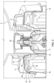
- Fig. 1A may serve as an illustration of an example of a top surface 18 of the keg gasket locking flange (15) which constitutes the top section of a substantially annular gasket part 10.
- the top surface may have an annular inner section and an annular outer section.
- Fig. 1B may serve as an illustration of an example of a top surface of the keg gasket locking flange (15) which constitutes the top section of a substantially annular gasket part (10).
- the top surface has an annular inner section and an annular outer section.
- the annular outer section may be arranged closer than the annular inner section to a top wall of the closure (11) in the sealed configuration.
- the annular inner section of the top surface of the keg gasket locking flange and the top wall of the closure may define an antenna space for the substantially planar annular antenna in the sealed configuration.
- the substantially planar annular antenna does not necessarily have to be placed on top of the top surface. There may be an additional sheath over the antenna, such as a plastic sheath.
- the substantially planar antenna may be entirely integrated in the in the substantially annular gasket part, such as integrated in the top section of the outer substantially annular gasket part.
- a substantially annular antenna space 21 is a space between the top wall of the closure and the annular inner section of the top surface.
- the substantially planar annular antenna may be arranged on the annular inner section of the top surface, or integrated in the outer substantially annular gasket part.
- the antenna may be designed to achieve certain minimum magnetic field strength requirements for the given physical constraints, i.e. the limitations in space and the position of the RFID tag. Two such standards are ISO/IEC 15693 and ISO/IEC 14443.
- the substantially planar annular antenna is integrated in a substantially planar annular printed circuit board and/or integrated in the substantially annular gasket part, such as integrated in the keg gasket locking flange and/or the top section of the outer substantially annular gasket part.
- the keg gasket locking flange may be made of a substantially rigid material, such as plastic or rubber, into which the substantially planar annular antenna may be molded or printed.
- the substantially planar annular printed circuit board may be adapted to fit in the antenna space. There may be an additional sheath over the antenna, such as a plastic sheath.
- the substantially planar annular printed circuit board may further comprise an interrogation circuit and further required electronic components and circuits.
- the interrogation circuit and/or further required electronic components and circuits may be mounted on a printed circuit board or other base piece, such as a plastic piece, for holding the antenna and components together.
- the interrogation circuit, or, alternatively the base piece, and/or the entire assembly may be placed on the substantially annular gasket part and/or be integrated in the substantially annular gasket part, such as integrated in the keg gasket locking flange and/or the top section of the outer substantially annular gasket part.
- the substantially planar annular antenna may be arranged with a first offset in height in relation to the radio-frequency identification tag on the keg and with a second offset in circumferential distance from the outer edge of the substantially planar annular antenna to the radio-frequency identification tag.
- the offset in height can be seen as the longitudinal extension of the keg and the pressure chamber in, for example, fig. 4 . Within the present disclosure, this may also be referred to as the Z dimension in a Cartesian coordinate system.
- the first offset may be seen as the distance between the substantially planar annular antenna and a center of the RFID tag in the Z dimension, as illustrated in fig. 1 .
- the first offset (Off 1 ) may be between 5.5 and 18.5 mm, such as between 5.5 mm and 15.5 mm, such as between 8.5 mm and 18.5 mm, preferably between 7.5 and 16.5, such as between 7.5 and 13.5, such as between 10.5 mm and 16.5 mm, such as 13.5 mm and in particular 10.5 mm.
- the second offset can be seen as the distance between the substantially planar annular antenna and the RFID tag in the X-Y dimension, i.e. in the extension of the planar antenna, as illustrated in fig. 1 .
- the second offset (Off 2 ) may be between 10.7 mm and 22.7 mm, preferably between 13.7 mm and 19.7 mm, such as 16.7 mm.
- the substantially planar annular antenna and the radio-frequency identification tag extend in substantially orthogonal directions, as illustrated in fig. 1 .
- the substantially planar annular antenna is configured to generate a magnetic field component orthogonal to the radio-frequency identification tag, wherein the magnetic field component has a local maximum at the radio-frequency identification tag.
- the substantially planar annular antenna may have a substantially circular shape.
- the substantially planar annular may therefore have a substantially circular inner edge and a substantially circular outer edge.
- the antenna may take a number of shapes in terms of, for example, number of turns.
- the substantially planar annular antenna may be a spiral antenna, such as a two turn spiral antenna, a single turn antenna or a two turn antenna, the substantially planar annular antenna having an outer diameter d out and an inner diameter d in .
- the outer diameter d out and an inner diameter d in are selected such that the antenna is in compliance with the dimensions of the pressure chamber and keg (i.e.
- the outer diameter of the substantially planar annular antenna may be between 70 mm and 110 mm, preferably between 80 mm and 100 mm, more preferably between 87 mm and 97 mm, such as 92 mm.
- the design of the antenna is selected such that the magnetic field is maximized outside the antenna in the X-Y dimension at the distance of the RFID tag in the X-Y plane, since the RFID tag may be located circumferentially outside the antenna on the outer rim of the closure.
- Trace width and spacing are parameters of planar antennas, such as the substantially planar annular antenna of the presently disclosed radio-frequency identification-equipped pressure chamber.
- the substantially planar annular antenna may be a spiral antenna.
- the spiral antenna may have a trace width w between 0.3 mm and 0.7 mm, such as 0.5 mm and a trace space g between 0.3 mm and 0.7 mm, such as 0.5 mm.
- the substantially planar annular antenna is a single turn antenna, it may have a trace width w of 1 mm and form a loop along the outer diameter d out and an inner diameter d in of the substantially planar annular antenna, as shown in the example of fig. 3B .
- the two turn antenna may have a trace width w between 0.3 mm and 0.7 mm, such as 0.5 mm, and a trace space g between 0.2 mm and 0.7 mm, such as 0.5 mm, and wherein the two turns form a loop along the outer diameter d out and an inner diameter d in of the substantially planar annular antenna.
- the two turns may be wrapped along a line orthogonal to the substantially circular inner edge and substantially circular outer edge.
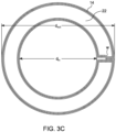
- Figs. 3A, 3B and 3C show embodiments of a substantially planar annular antenna.
- Fig. 3A shows a spiral antenna.
- Fig. 3B shows a single turn antenna.
- Fig. 3C shows a two turn antenna.
- Example of fig. 3A spiral antenna: Flat spiral antennas are known for their planar designed suitable for integration in, for example, a printed circuit board. Since the orientation of the plane where the tag antenna lies is orthogonal in relation to the plane of the reader antenna, the importance of the vertical component (Z-axis) of the field is limited as it does not produce the magnetic flux in the tag. The component that creates a net magnetic flux on the tag can be thought off as the curling behavior of the produced magnetic field at the center of the coil.
- Example of fig. 3B single turn antenna: In this embodiment the field is created closer to the periphery of the antenna where the RFID/NFC tag is located. The magnetic field is produced in the middle of the two traces of the antenna by two opposing currents as shown in fig. 3B .
- Example of fig. 3C two turn antenna: In this embodiment the two turns form a loop along the outer diameter d out and an inner diameter d in of the substantially planar annular antenna.
- the radio-frequency identification-equipped pressure chamber may further comprise a matching network, which is typically placed between the interrogation circuit and the antenna.
- RF transmission lines have a characteristic impedance, which is a factor in RF circuitry.
- impedances are matched to prevent standing waves and to ensure efficient transfer of power from source to load.
- the antenna is impedance matched in the operation environment so that it operates in the desired frequency band with maximum efficiency within the RFID spectrum of 125 kHz - 5,4GHz.
- a matching network may be designed according to the example of fig. 4 .
- the disclosure further relates to a pressure system for a beverage comprising the presently disclosed radio-frequency identification-equipped pressure chamber and a collapsible beverage container having a radio-frequency identification tag.
- the radio-frequency identification-equipped pressure may be any of the above embodiments.
- the pressure system can thereby be seen as an assembly comprising a collapsible beverage container and a pressure chamber for accommodating and encapsulating the collapsible beverage container.
- the pressure system may be part of a beverage dispensing system in the form of a modular system comprising a plurality of collapsible beverage containers and pressure chambers sharing a common tapping line.
- the pressure chamber of the pressure system may comprise:
- the inner connector part may be arranged on an inside of the lid part, and the outer substantially annular gasket part may be arranged on the inside of the lid part.
- the collapsible beverage container preferably comprise a closure with a beverage outlet.
- the closure has an outer rim and a radio-frequency identification tag arranged on said rim.
- the closure has an outer substantially cylindrical outer rim and a substantially cylindrical inner rim.
- the outlet of the collapsible container may be connected through an inner cylindrical or tubular connection inside the inner rim.
- the closure may further comprise a top wall covering at least the annular section defined by the inner rim and the outer rim. The outer rim, inner rim and top wall may thereby define the hollow annular space of the closure.
- the RFID tag on the collapsible container and the interrogation antenna and reader will enable monitoring useful information about the status of the pressure chamber and the keg itself, thereby increasing safety of the beverage dispensing system.
- the system can transmit and process information, in particular the system can process and store information about the beverage in the collapsible container both in terms of brand (content), remaining volume, days on the tap and so forth.
- the pressure status of the chamber can likewise be monitored, and a pressure drop to zero can be used to indicate that a new collapsible beverage container has been inserted into the system.
- Fig. 1A shows a cross-section of an outer substantially annular gasket part (10) of a base part or lid part of a pressure chamber inserted in a corresponding hollow annular space (24) of a closure of a beverage container.
- the substantially annular gasket part (10) comprises a substantially planar annular antenna (14) arranged in a space between the annular gasket part (10) and a top wall (11) of the closure.
- the closure has, besides the top wall (10) an outer rim (12), on which an RFID tag (8) is arranged, and an inner rim (13).
- the substantially annular gasket part (10) comprises a keg gasket locking flange (15), which constitutes a top section of the outer substantially annular gasket part (10).
- keg gasket locking flange Under the keg gasket locking flange (15), there is a, preferably resilient, keg gasket (16).
- the keg gasket locking flange (15) has a top surface (18) towards the top wall (11) of the closure.
- the substantially planar annular antenna (14) arranged between the annular keg gasket part (16) and keg gasket locking flange (15).
- Fig. 2 shows a cross-section of an outer substantially annular gasket part (10) of a base part (5) or lid part of a pressure chamber (1) partly inserted in a closure (17) of a keg (2).
- the substantially planar annular antenna and RFID tag are not mounted in fig. 2 .
- the substantially planar annular antenna can be mounted in the antenna space (21).
- the substantially annular gasket part (10) comprises a keg gasket locking flange (15), which constitutes a top section of the outer substantially annular gasket part (10). Under the keg gasket locking flange (15), there is a, preferably resilient, keg gasket (16).
- the annular antenna may be arranged between these two sections for maximum protection (illustrated in Fig. 1B ).
- the keg gasket locking flange (15) has a top surface (18) towards the top wall (11) of the closure (17).
- the top surface of the outer substantially annular gasket part (10) has an annular inner section (19) and an annular outer section (20).
- the substantially planar annular antenna (not visible in fig. 2 ) may alternatively be arranged on the annular outer section (20), optionally covered by a sheath, or, optionally integrated in, such as molded into, the substantially annular gasket part (10).
- the base part (5) of the pressure chamber (1) comprises an inner connector part (9) adapted to be engaged to a corresponding beverage container outlet (23).
- the closure (17) has, besides the top wall (10) an outer rim (12), on which an RFID tag (not visible in fig. 2 ) may be arranged, and an inner rim (13).
- Fig. 3A shows an embodiment of a substantially planar annular antenna (14), in the form of a spiral antenna, integrated in a base piece (22), such as a printed circuit board or a piece of plastic.
- the substantially planar annular antenna (14) has a substantially circular inner edge (25) and a substantially circular outer edge (26).
- the substantially planar annular antenna (14) has an outer diameter d out and an inner diameter d in .
- Fig. 3B shows an embodiment of a substantially planar annular antenna (14), in the form of a single turn antenna.
- the substantially planar annular antenna (14) has an outer diameter d out and an inner diameter d in .
- Fig. 3C shows an embodiment of a substantially planar annular antenna (14), in the form of a two turn antenna.
- the substantially planar annular antenna (14) has an outer diameter d out and an inner diameter d in .
- the two turns form a loop along the outer diameter d out and an inner diameter d in of the substantially planar annular antenna.
- the two turns are wrapped along a line orthogonal to the substantially circular inner edge and substantially circular outer edge.
- Fig. 4 shows an example of a simplified schematic of a matching network for the presently disclosed radio-frequency identification-equipped pressure chamber.
- Fig. 5 shows a perspective view of a modular beverage dispensing system (27) comprising three pressure chambers (1) with collapsible beverage-filled containers (2).
- the pressure chambers (1) each comprise a rigid base part (5) and a lid part (6).
- the beverage container (2) also known as keg, is of the collapsible type made of a collapsible polymeric material, thus the term collapsible beverage container.
- the collapsible beverage container (2) defines a beverage filled space containing the beverage (3), typically being a carbonated beverage such as beer.
- the beverage container (2) may also comprise a gas filled head space at its top portion, above the level of the beverage inside the beverage container (2).
- the lid part (6) and the rigid base part (5) are separable, but during operation, they are sealed together for defining the inner space (4) for accommodating the beverage container (2).
- the lid part (6) may e.g. be made of rubber.
- the collapsible beverage container (2) includes a closure (17) for cooperation with a coupler of a beverage dispensing system (27) through the base part (5), thereby connecting the collapsible beverage container (2) to a tapping line (28).
- the tapping line (28) passes through a cooling device (7) and further on to a tapping device (29).
Landscapes
- Engineering & Computer Science (AREA)
- Mechanical Engineering (AREA)
- Computer Networks & Wireless Communication (AREA)
- Computer Hardware Design (AREA)
- Microelectronics & Electronic Packaging (AREA)
- Physics & Mathematics (AREA)
- General Physics & Mathematics (AREA)
- Theoretical Computer Science (AREA)
- Closures For Containers (AREA)
- Details Of Rigid Or Semi-Rigid Containers (AREA)
- Support Of Aerials (AREA)
- Electron Tubes For Measurement (AREA)
- Accommodation For Nursing Or Treatment Tables (AREA)
- Surgical Instruments (AREA)
Claims (16)
- Druckkammer (1) mit Radiofrequenz-Identifikation für einen Getränkebehälter (2), wobei die Druckkammer Folgendes umfasst:- ein Deckelteil (6);- ein Basisteil (5), wobei der Deckel und das Basisteil einen abgedichteten Innenraum (4) zum Aufnehmen und Verkapseln des Getränkebehälters (2) definieren, wobei das Basisteil (5) oder das Deckelteil (6) Folgendes umfasst:∘ ein inneres Verbinderteil (9), das dazu geeignet ist, mit einem entsprechenden Getränkebehälterauslass (23) in Eingriff gebracht zu werden, wobei das innere Verbinderteil (9) an einer Innenseite des Basisteils (5) oder Deckelteils (6) angeordnet ist; und∘ ein äußeres, im Wesentlichen ringförmiges Dichtungsteil (10), das an der Innenseite des Basisteils (5) oder des Deckelteils (6) angeordnet ist und das innere Verbinderteil (9) umgibt, wobei das äußere, im Wesentlichen ringförmige Dichtungsteil (10) dazu geeignet ist, mit einem entsprechenden hohlen Ringraum (24) eines Verschlusses des Getränkebehälters (2) in Eingriff gebracht zu werden,
dadurch gekennzeichnet, dass;∘ das äußere, im Wesentlichen ringförmige Dichtungsteil (10) eine im Wesentlichen ebene ringförmige Antenne umfasst, die dazu geeignet ist, Funkwellen zu einem Radiofrequenz-Identifikationskennzeichen (8), das an einem Außenrand (12) des Verschlusses angeordnet ist, zu propagieren. - Druckkammer (1) mit Radiofrequenz-Identifikation nach Anspruch 1, dadurch gekennzeichnet, dass das äußere, im Wesentlichen ringförmige Dichtungsteil (10) so geformt ist, dass es in den entsprechenden hohlen Ringraum (24) des Verschlusses des Getränkebehälters (2) dichtend einführbar ist.
- Druckkammer (1) mit Radiofrequenz-Identifikation nach Anspruch 2, wobei das äußere, im Wesentlichen ringförmige Dichtungsteil (10) eine Deckfläche (18) mit einem ringförmigen Innenabschnitt (19) und einem ringförmigen Außenabschnitt (20) umfasst, wobei der ringförmige Außenabschnitt (20) näher als der ringförmige Innenabschnitt (19) an einer Deckwand des Verschlusses (11) in der abgedichteten Konfiguration angeordnet ist, und wobei der ringförmige Innenabschnitt (19) der Deckfläche (18) und die Deckwand des Verschlusses (11) einen Antennenraum (21) für die im Wesentlichen ebene ringförmige Antenne (14) in der abgedichteten Konfiguration definieren.
- Druckkammer (1) mit Radiofrequenz-Identifikation nach Anspruch 1 oder 2, wobei das äußere, im Wesentlichen ringförmige Dichtungsteil (10) einen Keg-Dichtung-Verriegelungsflansch (15) umfasst, wobei der Keg-Dichtung-Verriegelungsflansch (15) einen oberen Abschnitt des äußeren, im Wesentlichen ringförmigen Dichtungsteils bildet, und wobei die im Wesentlichen ebene ringförmige Antenne in dem oberen Abschnitt integriert ist.
- Druckkammer (1) mit Radiofrequenz-Identifikation nach einem der vorhergehenden Ansprüche, wobei das äußere, im Wesentlichen ringförmige Dichtungsteil (10) ferner eine Keg-Dichtung (16) umfasst, die unter dem Keg-Dichtung-Verriegelungsflansch (15) angeordnet ist, wobei vorzugsweise die Keg-Dichtung (16) aus einem elastischen Material oder einem Material hergestellt ist, das elastischer als das des Keg-Dichtung-Verriegelungsflansches (15) ist.
- Druckkammer (1) mit Radiofrequenz-Identifikation nach Anspruch 5, wobei die im Wesentlichen ebene ringförmige Antenne (14) zwischen dem Keg-Dichtung-Verriegelungsflansch (15) und der Keg-Dichtung (16) angeordnet ist.
- Druckkammer (1) mit Radiofrequenz-Identifikation nach einem der vorhergehenden Ansprüche, wobei die im Wesentlichen ebene ringförmige Antenne (14) in einer im Wesentlichen ebenen ringförmigen Leiterplatte integriert ist.
- Druckkammer (1) mit Radiofrequenz-Identifikation nach einem der vorhergehenden Ansprüche, wobei die im Wesentlichen ebene ringförmige Antenne (14) einen im Wesentlichen kreisförmigen Innenrand (25) und einen im Wesentlichen kreisförmigen Außenrand (26) aufweist, wobei die im Wesentlichen ebene ringförmige Antenne (14) eine Spiralantenne ist, wie etwa eine Zweiwindungsspiralantenne, eine Einwindungsantenne oder eine Zweiwindungsantenne, wobei die im Wesentlichen ebene ringförmige Antenne einen Außendurchmesser d out und einen Innendurchmesser d in aufweist.
- Druckkammer (1) mit Radiofrequenz-Identifikation nach Anspruch 8, dadurch gekennzeichnet, dass die Zweiwindungsantenne eine Spurbreite w zwischen 0,3 mm und 0,7 mm, wie etwa 0,5 mm, und einen Spurraum g zwischen 0,2 mm und 0,7 mm, wie etwa 0,5 mm, aufweist und dass die beiden Windungen eine Schleife entlang des Außendurchmessers d out und eines Innendurchmessers d in der im Wesentlichen ebenen Ringantenne (14) bilden.
- Druckkammer (1) mit Radiofrequenz-Identifikation nach einem der vorhergehenden Ansprüche, wobei eine im Wesentlichen ebene ringförmige Antenne (14) mit einem ersten Höhenversatz in Bezug auf das Radiofrequenz-Identifikationskennzeichen (8) und mit einem zweiten Umfangsversatz in einem Umfangsabstand von dem Außenrand der im Wesentlichen ebenen ringförmigen Antenne (26) zu der Radiofrequenzkennzeichnung (8) angeordnet ist.
- Druckkammer (1) mit Radiofrequenz-Identifikation nach Anspruch 10, wobei der erste Versatz zwischen 5,5 mm und 15,5 mm, vorzugsweise zwischen 7,5 mm und 13,5 mm, wie etwa 10,5 mm, beträgt.
- Druckkammer (1) mit Radiofrequenz-Identifikation nach einem der Ansprüche 10-11, wobei der zweite Versatz zwischen 10,7 mm und 22,7 mm, vorzugsweise zwischen 13,7 mm und 19,7 mm, wie etwa 16,7 mm, beträgt.
- Druckkammer (1) mit Radiofrequenz-Identifikation nach einem der vorhergehenden Ansprüche, wobei sich die im Wesentlichen ebene ringförmige Antenne (14) und das Radiofrequenz-Identifikationskennzeichen (8) in im Wesentlichen orthogonalen Richtungen erstrecken, und wobei die im Wesentlichen ebene ringförmige Antenne (14) angeordnet ist, um eine Magnetfeldkomponente orthogonal zu dem Radiofrequenz-Identifikationskennzeichen (8) zu erzeugen, wobei die Magnetfeldkomponente ein lokales Maximum an dem Radiofrequenz-Identifikationskennzeichen (8) aufweist.
- Druckkammer (1) mit Radiofrequenz-Identifikation nach einem der vorhergehenden Ansprüche, wobei die Radiofrequenz-Identifikation eine Nahfeld-Kommunikation ist und das Radiofrequenz-Identifikationskennzeichen (8) ein Nahfeld-Kommunikationskennzeichen ist.
- Drucksystem für ein Getränk (3), Folgendes umfassend:- einen zusammenklappbaren Getränkebehälter (2), umfassend einen Verschluss (17) mit einem Getränkeauslass (23), wobei der Verschluss einen Außenrand (12) und eine auf dem Rand angeordnetes Radiofrequenz-Identifikationskennzeichen (8) aufweist;- eine Druckkammer, Folgendes umfassend:∘ ein Deckelteil (6);∘ ein Basisteil (5), wobei das Deckelteil (6) und das Basisteil (5) einen abgedichteten Innenraum (4) zum Aufnehmen und Verkapseln des zusammenklappbaren Getränkebehälters (2) definieren, wobei das Basisteil (5) oder das Deckelteil (6) Folgendes umfasst:▪ ein inneres Verbinderteil (9), das dazu geeignet ist, mit dem Getränkebehälterauslass (23) in Eingriff gebracht zu werden, wobei das innere Verbinderteil (9) an einer Innenseite des Basisteils (5) oder Deckelteils (6) angeordnet ist; und▪ ein äußeres, im Wesentlichen ringförmiges Dichtungsteil (10), das an der Innenseite des Basisteils (5) oder des Deckelteils (6) angeordnet ist und das innere Verbinderteil (9) umgibt, wobei das äußere, im Wesentlichen ringförmige Dichtungsteil (10) dazu geeignet ist, mit einem entsprechenden hohlen Ringraum (24) des Verschlusses (17) des zusammenklappbaren Getränkebehälters (2) in Eingriff gebracht zu werden,
dadurch gekennzeichnet, dass;▪ das äußere, im Wesentlichen ringförmige Dichtungsteil (10) eine im Wesentlichen ebene ringförmige Antenne (14) umfasst, die dazu geeinget ist, das Radiofrequenz-Identifikationskennzeichen (8) zu propagieren. - Drucksystem nach Anspruch 15, wobei die Druckkammer die Druckkammer (1) mit Radiofrequenz-Identifikation nach einem der Ansprüche 1-14 ist.
Priority Applications (1)
| Application Number | Priority Date | Filing Date | Title |
|---|---|---|---|
| HRP20240140TT HRP20240140T1 (hr) | 2019-09-23 | 2020-09-23 | Tlačna komora opremljena rfid-om za bačvu |
Applications Claiming Priority (2)
| Application Number | Priority Date | Filing Date | Title |
|---|---|---|---|
| EP19199007 | 2019-09-23 | ||
| PCT/EP2020/076493 WO2021058520A1 (en) | 2019-09-23 | 2020-09-23 | Rfid-equipped pressure chamber for keg |
Publications (3)
| Publication Number | Publication Date |
|---|---|
| EP4034468A1 EP4034468A1 (de) | 2022-08-03 |
| EP4034468B1 true EP4034468B1 (de) | 2023-11-15 |
| EP4034468C0 EP4034468C0 (de) | 2023-11-15 |
Family
ID=68051732
Family Applications (1)
| Application Number | Title | Priority Date | Filing Date |
|---|---|---|---|
| EP20775635.4A Active EP4034468B1 (de) | 2019-09-23 | 2020-09-23 | Druckkammer für keg mit rfid |
Country Status (16)
| Country | Link |
|---|---|
| US (1) | US11975901B2 (de) |
| EP (1) | EP4034468B1 (de) |
| JP (1) | JP7645248B2 (de) |
| KR (1) | KR20220066267A (de) |
| CN (1) | CN114450230B (de) |
| AU (1) | AU2020354429A1 (de) |
| BR (1) | BR112022005302A2 (de) |
| CA (1) | CA3151887A1 (de) |
| ES (1) | ES2970371T3 (de) |
| HR (1) | HRP20240140T1 (de) |
| IL (1) | IL290968B2 (de) |
| MX (1) | MX2022003470A (de) |
| PL (1) | PL4034468T3 (de) |
| SA (1) | SA522431945B1 (de) |
| WO (1) | WO2021058520A1 (de) |
| ZA (1) | ZA202202130B (de) |
Families Citing this family (1)
| Publication number | Priority date | Publication date | Assignee | Title |
|---|---|---|---|---|
| EP4264582A1 (de) * | 2020-12-16 | 2023-10-25 | Fresh Blends Ltd | Intelligentes inventarverwaltungssystem für eine ausgabe- und mix-in-cup-getränkeplattform |
Family Cites Families (26)
| Publication number | Priority date | Publication date | Assignee | Title |
|---|---|---|---|---|
| GB2346604B (en) * | 1999-02-10 | 2003-10-08 | Skerra Pty Ltd | Improvements in fluid containers |
| US6628237B1 (en) * | 2000-03-25 | 2003-09-30 | Marconi Communications Inc. | Remote communication using slot antenna |
| US7224273B2 (en) * | 2002-05-23 | 2007-05-29 | Forster Ian J | Device and method for identifying a container |
| US7152781B2 (en) * | 2003-12-01 | 2006-12-26 | Advanced Technology Materials, Inc. | Manufacturing system with intrinsically safe electric information storage |
| FR2864040B1 (fr) * | 2003-12-19 | 2006-03-31 | Valois Sas | Organe de distribution de produit fluide et distributeur comprenant un tel organe |
| NL1025629C2 (nl) * | 2004-03-03 | 2005-09-07 | Dispense Systems Internat B V | Tapstang. |
| WO2006016559A1 (ja) * | 2004-08-09 | 2006-02-16 | Suncall Corporation | Icタグ付きシール及びその取り付け方法 |
| EP2206677B1 (de) * | 2005-08-12 | 2011-12-28 | Carlsberg Breweries A/S | Vorrichtung um einen flexiblen behälter mit einem getränkespender zu verbinden |
| JP4942440B2 (ja) * | 2006-09-29 | 2012-05-30 | 東洋製罐株式会社 | Icタグ付キャップ |
| DE102007060130A1 (de) * | 2007-12-15 | 2009-06-18 | Venoplas Ag | Flüssigkeitsspender |
| JP5114263B2 (ja) * | 2008-03-26 | 2013-01-09 | 理想科学工業株式会社 | 記録媒体を備えた開口容器 |
| JP5503880B2 (ja) * | 2009-02-27 | 2014-05-28 | 大和システム株式会社 | ドラム缶等容器用キャップシール、およびこれを用いたドラム缶等容器の二重密閉装置 |
| IL216929A (en) * | 2011-12-13 | 2014-06-30 | Strauss Water Ltd | Container with identification module and device for use |
| CH706037A2 (de) * | 2012-01-23 | 2013-07-31 | Francisco Speich | Heissgetränke-, insbesondere Kaffemaschine, mit Wasserbezug direkt aus handelsüblichen Einwegwasserbehältern. |
| NL2009864C2 (en) * | 2012-11-22 | 2014-05-27 | Heineken Supply Chain Bv | Beverage dispensing assembly and container for use in a beverage dispensing assembly. |
| DE202013005658U1 (de) * | 2013-06-22 | 2014-06-23 | Krones Ag | Zapfanlage und Behälter |
| DE202013007693U1 (de) | 2013-08-30 | 2013-10-28 | Ventarsys Gmbh | Trägerelement zur Befestigung an einem Getränkebehälter mit RFID-Transponder |
| US20160264394A1 (en) * | 2013-11-03 | 2016-09-15 | SteadyServ Technologies, LLC | Draft beer supply chain systems and methods |
| JP6225004B2 (ja) * | 2013-12-03 | 2017-11-01 | 株式会社Iro | バルブ開閉用のソケット嵌合部、バルブ、バルブ開閉器、バルブ情報読取装置 |
| CN204110543U (zh) * | 2014-09-01 | 2015-01-21 | 南通艾菲迪物联网科技有限公司 | 一种基于超高频射频技术的桶装水聪明盖结构 |
| CN108025899B (zh) * | 2015-05-28 | 2019-06-04 | 自动阻碍控制器股份有限公司 | 具有智能杯标签识别和验证的饮料分配装置 |
| ES2939370T3 (es) * | 2016-01-12 | 2023-04-21 | Freezio Ag | Sistema de dispensador con soporte para cartucho |
| EP3459024B1 (de) | 2016-05-20 | 2022-10-26 | Kegspeed, LLC | Verteilungsnetz zur überwachung, steuerung und optimierung des flusses von über behälter an kunden abgegebenen flüssigen getränkeprodukten |
| JP2019084766A (ja) * | 2017-11-08 | 2019-06-06 | セイコーエプソン株式会社 | インク収容ボトル |
| UA128132C2 (uk) * | 2018-02-13 | 2024-04-17 | Карлсберг Бреверіс А/С | Система розливу напоїв, яка містить одноразові бочонки, що стискаються |
| CN208393836U (zh) * | 2018-06-06 | 2019-01-18 | 深圳塑研科技有限公司 | 一种含射频标签的饮水桶 |
-
2020
- 2020-09-23 EP EP20775635.4A patent/EP4034468B1/de active Active
- 2020-09-23 US US17/762,538 patent/US11975901B2/en active Active
- 2020-09-23 KR KR1020227008252A patent/KR20220066267A/ko active Pending
- 2020-09-23 PL PL20775635.4T patent/PL4034468T3/pl unknown
- 2020-09-23 ES ES20775635T patent/ES2970371T3/es active Active
- 2020-09-23 MX MX2022003470A patent/MX2022003470A/es unknown
- 2020-09-23 HR HRP20240140TT patent/HRP20240140T1/hr unknown
- 2020-09-23 WO PCT/EP2020/076493 patent/WO2021058520A1/en not_active Ceased
- 2020-09-23 CA CA3151887A patent/CA3151887A1/en active Pending
- 2020-09-23 JP JP2022517987A patent/JP7645248B2/ja active Active
- 2020-09-23 CN CN202080067013.4A patent/CN114450230B/zh active Active
- 2020-09-23 AU AU2020354429A patent/AU2020354429A1/en active Pending
- 2020-09-23 BR BR112022005302A patent/BR112022005302A2/pt not_active Application Discontinuation
-
2022
- 2022-02-18 ZA ZA2022/02130A patent/ZA202202130B/en unknown
- 2022-02-28 IL IL290968A patent/IL290968B2/en unknown
- 2022-03-13 SA SA522431945A patent/SA522431945B1/ar unknown
Also Published As
| Publication number | Publication date |
|---|---|
| IL290968B2 (en) | 2023-06-01 |
| CN114450230A (zh) | 2022-05-06 |
| CN114450230B (zh) | 2024-07-12 |
| MX2022003470A (es) | 2022-04-19 |
| WO2021058520A1 (en) | 2021-04-01 |
| CA3151887A1 (en) | 2021-04-01 |
| HRP20240140T1 (hr) | 2024-04-12 |
| JP2022548763A (ja) | 2022-11-21 |
| EP4034468A1 (de) | 2022-08-03 |
| US11975901B2 (en) | 2024-05-07 |
| ES2970371T3 (es) | 2024-05-28 |
| IL290968A (en) | 2022-05-01 |
| SA522431945B1 (ar) | 2022-12-18 |
| PL4034468T3 (pl) | 2024-04-15 |
| ZA202202130B (en) | 2025-06-25 |
| AU2020354429A1 (en) | 2022-03-10 |
| EP4034468C0 (de) | 2023-11-15 |
| JP7645248B2 (ja) | 2025-03-13 |
| BR112022005302A2 (pt) | 2022-06-14 |
| KR20220066267A (ko) | 2022-05-24 |
| US20220355971A1 (en) | 2022-11-10 |
Similar Documents
| Publication | Publication Date | Title |
|---|---|---|
| US12291443B2 (en) | Beverage dispense valve controlled by wireless technology | |
| CN111727166B (zh) | 包括一次性使用的可收缩桶的饮料分配系统 | |
| US6354468B1 (en) | Beverage dispenser transponder identification system | |
| RU2417939C2 (ru) | Способ и устройство для отпуска и/или хранения продуктов, в частности напитков | |
| EP1506523A2 (de) | Vorrichtung und verfahren zur identifikation eines behälters | |
| US20110102150A1 (en) | Metallic cover having ic tag, and metallic container | |
| EP4034468B1 (de) | Druckkammer für keg mit rfid | |
| EP2242394B1 (de) | Behälter für parfums, deodorants, cremes, schäume und gels | |
| WO2004056695A1 (en) | Beverage dispenser with authenticating key | |
| HK40078176A (en) | Rfid-equipped pressure chamber for keg | |
| HK40078176B (en) | Rfid-equipped pressure chamber for keg | |
| EP1152956B1 (de) | Verbesserungen für flüssigkeitsbehälter | |
| EA046568B1 (ru) | Оборудованная rfid камера избыточного давления для бочонка | |
| US20250066180A1 (en) | Pressure activated dispense system and components | |
| JP7467845B2 (ja) | Rfタグラベルおよびこれを貼付した商品 |
Legal Events
| Date | Code | Title | Description |
|---|---|---|---|
| STAA | Information on the status of an ep patent application or granted ep patent |
Free format text: STATUS: UNKNOWN |
|
| STAA | Information on the status of an ep patent application or granted ep patent |
Free format text: STATUS: THE INTERNATIONAL PUBLICATION HAS BEEN MADE |
|
| PUAI | Public reference made under article 153(3) epc to a published international application that has entered the european phase |
Free format text: ORIGINAL CODE: 0009012 |
|
| STAA | Information on the status of an ep patent application or granted ep patent |
Free format text: STATUS: REQUEST FOR EXAMINATION WAS MADE |
|
| 17P | Request for examination filed |
Effective date: 20220413 |
|
| AK | Designated contracting states |
Kind code of ref document: A1 Designated state(s): AL AT BE BG CH CY CZ DE DK EE ES FI FR GB GR HR HU IE IS IT LI LT LU LV MC MK MT NL NO PL PT RO RS SE SI SK SM TR |
|
| DAV | Request for validation of the european patent (deleted) | ||
| DAX | Request for extension of the european patent (deleted) | ||
| REG | Reference to a national code |
Ref country code: HK Ref legal event code: DE Ref document number: 40078176 Country of ref document: HK |
|
| GRAP | Despatch of communication of intention to grant a patent |
Free format text: ORIGINAL CODE: EPIDOSNIGR1 |
|
| STAA | Information on the status of an ep patent application or granted ep patent |
Free format text: STATUS: GRANT OF PATENT IS INTENDED |
|
| INTG | Intention to grant announced |
Effective date: 20230602 |
|
| GRAS | Grant fee paid |
Free format text: ORIGINAL CODE: EPIDOSNIGR3 |
|
| GRAA | (expected) grant |
Free format text: ORIGINAL CODE: 0009210 |
|
| STAA | Information on the status of an ep patent application or granted ep patent |
Free format text: STATUS: THE PATENT HAS BEEN GRANTED |
|
| AK | Designated contracting states |
Kind code of ref document: B1 Designated state(s): AL AT BE BG CH CY CZ DE DK EE ES FI FR GB GR HR HU IE IS IT LI LT LU LV MC MK MT NL NO PL PT RO RS SE SI SK SM TR |
|
| REG | Reference to a national code |
Ref country code: CH Ref legal event code: EP Ref country code: GB Ref legal event code: FG4D |
|
| REG | Reference to a national code |
Ref country code: DE Ref legal event code: R096 Ref document number: 602020021176 Country of ref document: DE |
|
| REG | Reference to a national code |
Ref country code: IE Ref legal event code: FG4D |
|
| U01 | Request for unitary effect filed |
Effective date: 20231211 |
|
| U07 | Unitary effect registered |
Designated state(s): AT BE BG DE DK EE FI FR IT LT LU LV MT NL PT SE SI Effective date: 20231215 |
|
| REG | Reference to a national code |
Ref country code: NO Ref legal event code: T2 Effective date: 20231115 |
|
| PG25 | Lapsed in a contracting state [announced via postgrant information from national office to epo] |
Ref country code: GR Free format text: LAPSE BECAUSE OF FAILURE TO SUBMIT A TRANSLATION OF THE DESCRIPTION OR TO PAY THE FEE WITHIN THE PRESCRIBED TIME-LIMIT Effective date: 20240216 |
|
| PG25 | Lapsed in a contracting state [announced via postgrant information from national office to epo] |
Ref country code: IS Free format text: LAPSE BECAUSE OF FAILURE TO SUBMIT A TRANSLATION OF THE DESCRIPTION OR TO PAY THE FEE WITHIN THE PRESCRIBED TIME-LIMIT Effective date: 20240315 |
|
| REG | Reference to a national code |
Ref country code: HR Ref legal event code: T1PR Ref document number: P20240140 Country of ref document: HR |
|
| PG25 | Lapsed in a contracting state [announced via postgrant information from national office to epo] |
Ref country code: IS Free format text: LAPSE BECAUSE OF FAILURE TO SUBMIT A TRANSLATION OF THE DESCRIPTION OR TO PAY THE FEE WITHIN THE PRESCRIBED TIME-LIMIT Effective date: 20240315 Ref country code: GR Free format text: LAPSE BECAUSE OF FAILURE TO SUBMIT A TRANSLATION OF THE DESCRIPTION OR TO PAY THE FEE WITHIN THE PRESCRIBED TIME-LIMIT Effective date: 20240216 |
|
| REG | Reference to a national code |
Ref country code: ES Ref legal event code: FG2A Ref document number: 2970371 Country of ref document: ES Kind code of ref document: T3 Effective date: 20240528 |
|
| PG25 | Lapsed in a contracting state [announced via postgrant information from national office to epo] |
Ref country code: RS Free format text: LAPSE BECAUSE OF FAILURE TO SUBMIT A TRANSLATION OF THE DESCRIPTION OR TO PAY THE FEE WITHIN THE PRESCRIBED TIME-LIMIT Effective date: 20231115 |
|
| PG25 | Lapsed in a contracting state [announced via postgrant information from national office to epo] |
Ref country code: CZ Free format text: LAPSE BECAUSE OF FAILURE TO SUBMIT A TRANSLATION OF THE DESCRIPTION OR TO PAY THE FEE WITHIN THE PRESCRIBED TIME-LIMIT Effective date: 20231115 |
|
| PG25 | Lapsed in a contracting state [announced via postgrant information from national office to epo] |
Ref country code: SK Free format text: LAPSE BECAUSE OF FAILURE TO SUBMIT A TRANSLATION OF THE DESCRIPTION OR TO PAY THE FEE WITHIN THE PRESCRIBED TIME-LIMIT Effective date: 20231115 |
|
| PG25 | Lapsed in a contracting state [announced via postgrant information from national office to epo] |
Ref country code: SM Free format text: LAPSE BECAUSE OF FAILURE TO SUBMIT A TRANSLATION OF THE DESCRIPTION OR TO PAY THE FEE WITHIN THE PRESCRIBED TIME-LIMIT Effective date: 20231115 Ref country code: SK Free format text: LAPSE BECAUSE OF FAILURE TO SUBMIT A TRANSLATION OF THE DESCRIPTION OR TO PAY THE FEE WITHIN THE PRESCRIBED TIME-LIMIT Effective date: 20231115 Ref country code: RO Free format text: LAPSE BECAUSE OF FAILURE TO SUBMIT A TRANSLATION OF THE DESCRIPTION OR TO PAY THE FEE WITHIN THE PRESCRIBED TIME-LIMIT Effective date: 20231115 Ref country code: CZ Free format text: LAPSE BECAUSE OF FAILURE TO SUBMIT A TRANSLATION OF THE DESCRIPTION OR TO PAY THE FEE WITHIN THE PRESCRIBED TIME-LIMIT Effective date: 20231115 |
|
| REG | Reference to a national code |
Ref country code: DE Ref legal event code: R097 Ref document number: 602020021176 Country of ref document: DE |
|
| PLBE | No opposition filed within time limit |
Free format text: ORIGINAL CODE: 0009261 |
|
| STAA | Information on the status of an ep patent application or granted ep patent |
Free format text: STATUS: NO OPPOSITION FILED WITHIN TIME LIMIT |
|
| REG | Reference to a national code |
Ref country code: HR Ref legal event code: ODRP Ref document number: P20240140 Country of ref document: HR Payment date: 20240822 Year of fee payment: 5 |
|
| U20 | Renewal fee for the european patent with unitary effect paid |
Year of fee payment: 5 Effective date: 20240911 |
|
| 26N | No opposition filed |
Effective date: 20240819 |
|
| PG25 | Lapsed in a contracting state [announced via postgrant information from national office to epo] |
Ref country code: MC Free format text: LAPSE BECAUSE OF FAILURE TO SUBMIT A TRANSLATION OF THE DESCRIPTION OR TO PAY THE FEE WITHIN THE PRESCRIBED TIME-LIMIT Effective date: 20231115 |
|
| PG25 | Lapsed in a contracting state [announced via postgrant information from national office to epo] |
Ref country code: IE Free format text: LAPSE BECAUSE OF NON-PAYMENT OF DUE FEES Effective date: 20240923 |
|
| REG | Reference to a national code |
Ref country code: HR Ref legal event code: ODRP Ref document number: P20240140 Country of ref document: HR Payment date: 20250825 Year of fee payment: 6 |
|
| REG | Reference to a national code |
Ref country code: CH Ref legal event code: U11 Free format text: ST27 STATUS EVENT CODE: U-0-0-U10-U11 (AS PROVIDED BY THE NATIONAL OFFICE) Effective date: 20251001 |
|
| PGFP | Annual fee paid to national office [announced via postgrant information from national office to epo] |
Ref country code: NO Payment date: 20250912 Year of fee payment: 6 |
|
| PGFP | Annual fee paid to national office [announced via postgrant information from national office to epo] |
Ref country code: PL Payment date: 20250821 Year of fee payment: 6 |
|
| U20 | Renewal fee for the european patent with unitary effect paid |
Year of fee payment: 6 Effective date: 20250910 |
|
| PGFP | Annual fee paid to national office [announced via postgrant information from national office to epo] |
Ref country code: GB Payment date: 20250910 Year of fee payment: 6 |
|
| PGFP | Annual fee paid to national office [announced via postgrant information from national office to epo] |
Ref country code: HR Payment date: 20250825 Year of fee payment: 6 |
|
| PGFP | Annual fee paid to national office [announced via postgrant information from national office to epo] |
Ref country code: CH Payment date: 20251001 Year of fee payment: 6 |
|
| PG25 | Lapsed in a contracting state [announced via postgrant information from national office to epo] |
Ref country code: CY Free format text: LAPSE BECAUSE OF FAILURE TO SUBMIT A TRANSLATION OF THE DESCRIPTION OR TO PAY THE FEE WITHIN THE PRESCRIBED TIME-LIMIT; INVALID AB INITIO Effective date: 20200923 |
|
| PGFP | Annual fee paid to national office [announced via postgrant information from national office to epo] |
Ref country code: ES Payment date: 20251010 Year of fee payment: 6 |
|
| PG25 | Lapsed in a contracting state [announced via postgrant information from national office to epo] |
Ref country code: HU Free format text: LAPSE BECAUSE OF FAILURE TO SUBMIT A TRANSLATION OF THE DESCRIPTION OR TO PAY THE FEE WITHIN THE PRESCRIBED TIME-LIMIT; INVALID AB INITIO Effective date: 20200923 |