EP4034458B1 - Propeller für ein wasserfahrzeug - Google Patents
Propeller für ein wasserfahrzeug Download PDFInfo
- Publication number
- EP4034458B1 EP4034458B1 EP20775610.7A EP20775610A EP4034458B1 EP 4034458 B1 EP4034458 B1 EP 4034458B1 EP 20775610 A EP20775610 A EP 20775610A EP 4034458 B1 EP4034458 B1 EP 4034458B1
- Authority
- EP
- European Patent Office
- Prior art keywords
- propeller
- rotation
- axis
- transition point
- smallest distance
- Prior art date
- Legal status (The legal status is an assumption and is not a legal conclusion. Google has not performed a legal analysis and makes no representation as to the accuracy of the status listed.)
- Active
Links
Images


Classifications
-
- B—PERFORMING OPERATIONS; TRANSPORTING
- B63—SHIPS OR OTHER WATERBORNE VESSELS; RELATED EQUIPMENT
- B63H—MARINE PROPULSION OR STEERING
- B63H5/00—Arrangements on vessels of propulsion elements directly acting on water
- B63H5/07—Arrangements on vessels of propulsion elements directly acting on water of propellers
- B63H5/08—Arrangements on vessels of propulsion elements directly acting on water of propellers of more than one propeller
- B63H5/10—Arrangements on vessels of propulsion elements directly acting on water of propellers of more than one propeller of coaxial type, e.g. of counter-rotative type
-
- B—PERFORMING OPERATIONS; TRANSPORTING
- B63—SHIPS OR OTHER WATERBORNE VESSELS; RELATED EQUIPMENT
- B63H—MARINE PROPULSION OR STEERING
- B63H1/00—Propulsive elements directly acting on water
- B63H1/02—Propulsive elements directly acting on water of rotary type
- B63H1/12—Propulsive elements directly acting on water of rotary type with rotation axis substantially in propulsive direction
- B63H1/14—Propellers
- B63H1/26—Blades
-
- B—PERFORMING OPERATIONS; TRANSPORTING
- B63—SHIPS OR OTHER WATERBORNE VESSELS; RELATED EQUIPMENT
- B63H—MARINE PROPULSION OR STEERING
- B63H1/00—Propulsive elements directly acting on water
- B63H1/02—Propulsive elements directly acting on water of rotary type
- B63H1/12—Propulsive elements directly acting on water of rotary type with rotation axis substantially in propulsive direction
- B63H1/14—Propellers
- B63H1/18—Propellers with means for diminishing cavitation, e.g. supercavitation
Definitions
- the present invention relates to a propeller according to the preamble of claim 1. Moreover, the present invention relates to a propeller combination as well as a marine vessel.
- the invention can be used in marine propulsion applications. Although the invention will be described with respect to a boat, the invention is not restricted to this particular marine vessel, but may also be used in other marine vessels such as ships, submarines etcetera. Furthermore, the invention can be used in applications not necessarily related to marine propulsion.
- a propeller assembly comprising one or more propellers is commonly used for propelling a marine vessel, such as a boat.
- a propeller rotating around and axis of rotation may generate a so called slip stream extending downstream the propeller.
- the slip stream may have the shape of a cone the envelope surface of which may follow a parabolic function, as seen along a side plane view of the propeller in a plane that extends parallel to the axis of rotation.
- Such a slip stream may cause undesired effects, such as cavitation effects of the propeller generating the slip stream and/or cavitation effects of a further propeller located downstream the slip stream generating propeller.
- US 2007/0098559 A1 proposes that a downstream propeller may have a diameter being smaller than the diameter of an upstream propeller in order to ensure that the envelope of the downstream propeller is located within a slip stream cone generated by the upstream propeller. Moreover, US 2007/0098559 A1 proposes that the upstream propeller be furnished with outer edges extending parallel to an axis of rotation of the propellers.
- KR 2016 0024021 A relates to a propulsion apparatus for a ship comprising: a double reverse propeller composed of a rear propeller and a front propeller; a reverse rotation device rotating the front propeller in the direction opposite to the rotation direction of the rear propeller; a forcedly fitting flange having a rear end made of a hollow tube and a front end made of a bolt coupling unit; an internal shaft coupling a rear end to the rear propeller and coupling a front end to a driving shaft by the forcedly fitting flange in a forcedly fitting/flange connection manner; and an external shaft coupling a rear end to the front propeller and coupling a front end to the driving shaft.
- the propulsion apparatus for the ship is made of a hollow tube forming a first taper unit with a taper shape that an inner diameter gets larger toward the rear side of the rear end; has the forcedly fitting flange with the front end made of the bolt coupling unit; forms a second taper unit at the front end of the inner shaft with a taper shape that an outer diameter gets smaller toward the front side; and arranges a driving shaft flange at the rear end of the driving shaft, to couple the front end of the inner shaft to the rear end of the forced fitting flange in a forced fitting connection manner and to couple the rear end of the driving shaft to the front end of the forcedly fitting flange in a flange connection manner, thereby being capable of coupling the inner shaft to the driving shaft in a forcedly fitting/flange connection manner to enhance the reliability of a shaft system due to increase of a coupling force between the inner shaft and the driving shaft.
- An object of a first aspect of the present invention is to provide a propeller that can produce an adequate propulsion force but at the same time is associated with a relatively low risk of cavitation problems.
- the first aspect of the present invention relates to a propeller for a marine vessel.
- the propeller comprises a plurality of propeller blades.
- the propeller is adapted to be rotated around an axis of rotation.
- Each one of the propeller blades comprises an edge that in turn comprises a leading edge, a trailing edge and an outer edge located between the leading edge and the trailing edge, as seen along the edge of the propeller blade.
- a transition from the leading edge to the outer edge occurs at a first transition point and a transition from the outer edge to the trailing edge occurs at a second transition point.
- a straight line from the first transition point to the second transition point coincides with the outer edge or is located at least partially outside the propeller blade.
- a smallest distance from the second transition point to the axis of rotation is smaller than a smallest distance from the first transition point to the axis of rotation, and wherein, as seen in said side plane view of said propeller blade, a length of said outer edge along said axis of rotation is equal to or greater than 20 % of the maximum length of the propeller blade along said axis of rotation, where each of the transition points is arranged at ends of the outer edge where the extension of the outer edge does not coincide with the straight line and where the edge bends off towards said axis of rotation forming one of said leading edge or said trailing edge, when seen in said plane.
- the first transition point is the outermost point, as seen in a radial direction from the axis of rotation, of the propeller blade. Consequently, the outer edge extends out to the radial outermost portion of the propeller blade, thus further reducing the risk of cavitation issues.
- the first and the second transition points are corners with a curvature radius smaller than 1/10 of a diameter of the propeller, or preferably smaller than 1/50 of a diameter of the propeller.
- two relatively sharp transition points are arranged in order to provide an outer edge that is clearly distinct from the leading edge and the trailing edge, in order to be able to reduce the risk of cavitation issues.
- a length equal to or greater than 20 % of maximum length of the propeller blade along said axis of rotation implies that a relatively large portion of the propeller blade may form a part of the outer edge, thus implying that an appropriate propulsion effect may be obtained from the propeller.
- the length of the outer edge along the axis of rotation is equal to or less than 50 % of the maximum length of the propeller blade along the axis of rotation.
- a length equal to or less than 50 % implies that a relatively large portion of the propeller blade may be designed with a focus on the propulsion effect rather than cavitation avoidance.
- the length of the outer edge along the axis of rotation is equal to or less than 40 % of the maximum length of the propeller blade along the axis of rotation.
- a length equal to or less than 40 % implies that a relatively large portion of the propeller blade may be designed with a focus on the propulsion effect rather than cavitation avoidance.
- the smallest distance from the second transition point to the axis of rotation is equal to or less than 99% of the smallest distance from the first transition point to the axis of rotation.
- a smallest relative distance as defined above implies a reduced risk for a portion of the outer edge adjacent to the second transition point to encounter cavitation related effects.
- the smallest distance from the second transition point to the axis of rotation is equal to or less than 95% of the smallest distance from the first transition point to the axis of rotation.
- a smallest relative distance as defined above implies a reduced risk for a portion of the outer edge adjacent to the second transition point to encounter cavitation related effects.
- the smallest distance from the second transition point to the axis of rotation is equal to or greater than 70% of the smallest distance from the first transition point to the axis of rotation.
- a smallest relative distance as defined above implies that an appropriate propulsion effect may be obtained from the propeller.
- the smallest distance from the second transition point to the axis of rotation is equal to or greater than 75% of the smallest distance from the first transition point to the axis of rotation.
- a smallest relative distance as defined above implies that an appropriate propulsion effect may be obtained from the propeller.
- a second aspect of the present invention relates to a propeller combination comprising a forward propeller and an after propeller, the propellers are adapted to rotate in opposite directions around the axis of rotation, at least one of the forward propeller and the after propeller being a propeller according to the first aspect of the present invention.
- each one of the forward propeller and the after propeller is a propeller according to the first aspect of the present invention.
- the smallest distance from the first transition point to the axis of rotation for the after propeller is smaller than a smallest distance from the second transition point to the axis of rotation for the forward propeller.
- a third aspect of the present invention relates to a marine vessel comprising a propeller according to the first aspect of the present invention and/or a propeller combination according to the second aspect of the present invention.
- the invention will be described below for a marine vessel in the form of a boat 10 such as the boat illustrated in Fig. 1 .
- the boat 10 should be seen as an example of a marine vessel which could comprise a propeller and/or propeller combination according to the present invention.
- the present invention may be implemented in a plurality of different types of marine vessels. Purely by way of example, the present invention could be implemented in a ship, a submarine or in a thruster intended for a semisubmersible unit.
- the Fig. 1 boat 10 comprises a hull 12 and tractor-type drive 14.
- the drive 14 illustrated in Fig. 1 is configured to be mounted to the stern 16 of the hull 12 but it is also contemplated that other implementations of the drive may be configured to be mounted to other portions of a hull.
- the drive 14 includes at least one pulling (or tractor) propeller, which can be configured as a propeller combination, comprising a forward propeller 18 and an after propeller 20, mounted to a front end of a gear case 22.
- the forward and after propellers 18, 20 in the illustrated embodiment are a pair of counter-rotating propellers mounted on coaxially rotating shafts.
- the present invention can be applied for a single propeller.
- the present invention can be applied for a pushing single propeller or a pushing propeller combination.
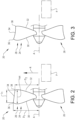
- Fig 2 illustrates an embodiment of a propeller 20 according to the first aspect of the present invention.
- the Fig. 2 propeller 20 may be adapted to form part of a pulling (or tractor) propeller or propeller combination, such as the Fig. 1 propeller combination, or a pushing propeller or propeller combination.
- the propeller 20 comprises a plurality of propeller blades 24, 26. In the Fig. 2 view, two propeller blades are visible but it is contemplated that embodiments of the propeller may comprise at least three propeller blades.
- the propeller 20 is adapted to be rotated around an axis of rotation A.
- each one of the propeller blades 24, 26 comprises an edge 28 that in turn comprises a leading edge 30, a trailing edge 32 and an outer edge 34 located between the leading edge 30 and the trailing edge 32, as seen along the edge 28 of the propeller blade 24.
- a transition from the leading edge 30 to the outer edge 34 occurs at a first transition point 36 and a transition from the outer edge 34 to the trailing edge 32 occurs at a second transition point 38.
- a straight line from the first transition point 36 to the second transition point 38 coincides with the outer edge 34 or is located at least partially outside the propeller blade 24.
- the outer edge 34 follows a substantially straight line. This means that when the outer edge follows the straight line this would result in that the outer edge follows a section of an envelope of an imaginary cone when the propeller rotates.
- Fig. 3 illustrates another embodiment of the propeller wherein the outer edge 24 has a parabolic shape, as seen in the plane P that extends parallel to the axis of rotation A.
- a smallest distance D 2 from the second transition point 38 to the axis of rotation A is smaller than a smallest distance D1 from the first transition point 36 to the axis of rotation A.
- the smallest distances may be the distance from the axis of rotation A to the first transition point 36 and the second transition point 38, respectively, in a direction being parallel to a radial axis R.
- Each of the transition points 36, 38 is arranged at ends of the outer edge 34 where the extension of the outer edge does not coincide with the straight line and where the edge bends off towards said axis of rotation A, thus the edge now forming one of said leading edge 30 or said trailing edge 32, when seen in said plane P.
- the first transition point 36 is the outermost point, as seen in a radial direction from the axis of rotation, of the propeller blade 24.
- the smallest distance D 1 from the first transition point 36 to the axis of rotation A is larger than the smallest distance from any other point on the edge 28 of the propeller blade 24 to the axis of rotation A.
- first and the second transition points are corners with a curvature radius smaller than 1/10 of a diameter of the propeller, or preferably smaller than 1/50 of a diameter of the propeller.
- two relatively sharp transition points are preferably arranged. This provides an outer edge that is clearly distinct from the leading edge and the trailing edge through respective first and second transition points. Arranging clear transition points will provide a more pure function according to the invention to the outer edge, which is to be able to reduce the risk of cavitation issues.
- the length L 1 of the outer edge 34 along the axis of rotation A may be equal to or greater than 5 %, preferably equal to or greater than 20 %, of the maximum length L tot of the propeller blade 24 along the axis of rotation A.
- the length L 1 of the outer edge 34 along the axis of rotation A is equal to or less than 50 %, preferably equal to or less than 40 %, of the maximum length L tot of the propeller blade 24 along the axis of rotation A.
- the smallest distance D 2 from the second transition point 38 to the axis of rotation A may be equal to or less than 99% , preferably equal to or less than 95%, of the smallest distance D 1 from the first transition point 36 to the axis of rotation A.
- the smallest distance D 2 from the second transition point to the axis of rotation may be equal to or greater than 70%, preferably equal to or greater than 75%, of the smallest distance from the first transition point to the axis of rotation.
- the ratio between the distances D 1 , D 2 as well as the length L 1 of the outer edge 34 may be selected on the basis of a predicted slip stream shape generated by the propeller itself or by another component, such as another propeller, located upstream of the propeller.
- the distances D 1 , D 2 , and possibly also the length L 1 may be such that the outer edge 34 is within the predicted slip stream, thereby reducing the risk for cavitation associated disturbances, but close to the slip stream to thereby obtain a large propeller area.
- Fig. 4 illustrates an embodiment of a propeller combination 40 comprising a forward propeller 18 and an after propeller 20.
- the propellers 18, 20 are adapted to rotate in opposite directions around the axis of rotation A.
- At least one of the forward propeller 18 and the after propeller 20 is a propeller according to the first aspect of the present invention, for instance as exemplified above with reference to Fig. 2 or Fig. 3 .
- each one of the forward propeller 18 and the after propeller 20 is a propeller according to the first aspect of the present invention.
- the smallest distance D 1 from the first transition point to the axis of rotation A for the after propeller 20 is smaller than a smallest distance from the second transition point D 2 to the axis of rotation A for the forward propeller 18.
Landscapes
- Chemical & Material Sciences (AREA)
- Engineering & Computer Science (AREA)
- Combustion & Propulsion (AREA)
- Mechanical Engineering (AREA)
- Ocean & Marine Engineering (AREA)
- Structures Of Non-Positive Displacement Pumps (AREA)
Claims (10)
- Propellerkombination (40), umfassend einen vorderen Propeller (18) und einen hinteren Propeller (20), wobei die Propeller angepasst sind, um in entgegengesetzten Richtungen um die Rotationsachse (A) zu rotieren, wobei jeder des vorderen Propellers (18) und des hinteren Propellers (20) ein Propeller gemäß dem Folgenden ist:ein Propeller (20) für ein Schiff (10), der Propeller (20) umfassend eine Vielzahl von Propellerblättern (24, 26), wobei der Propeller (20) angepasst ist, um um eine Rotationsachse (A) rotiert zu werden,jedes der Propellerblätter (24, 26) umfassend eine Kante (28), die wiederum eine Vorderkante (30), eine Hinterkante (32) und eine Außenkante (34) umfasst, die sich zwischen der Vorderkante (30) und der Hinterkante (32) befindet, wie entlang der Kante (28) des Propellerblatts (24) gesehen,wobei ein Übergang von der Vorderkante (30) zu der Außenkante (34) an einem ersten Übergangspunkt (36) stattfindet, und ein Übergang von der Außenkante (34) zu der Hinterkante (32) an einem zweiten Übergangspunkt (38) stattfindet,wobei, wie in einer Seitenebenenansicht des Propellerblatts in einer Ebene (P), die sich parallel zu der Rotationsachse (A) erstreckt, gesehen, deckt sich eine gerade Linie von dem ersten Übergangspunkt (36) zu dem zweiten Übergangspunkt (38) mit der Außenkante (34) oder befindet sich mindestens teilweise außerhalb des Propellerblatts (24),wobei ein kleinster Abstand (D2) von dem zweiten Übergangspunkt (38) zu der Rotationsachse (A) kleiner als ein kleinster Abstand (D1) von dem ersten Übergangspunkt (36) zu der Rotationsachse (A) ist,wobei, wie in der Seitenebenenansicht des Propellerblatts (24) gesehen, eine Länge (L1) der Außenkante (34) entlang der Rotationsachse (A) gleich oder größer als 20 % der maximalen Länge (Ltot) des Propellerblatts (24) entlang der Rotationsachse (A) ist,wo jeder der Übergangspunkte an Enden der Außenkante angeordnet ist, wo die Verlängerung der Außenkante sich nicht mit der geraden Linie deckt, und wo die Kante zu der Rotationsachse abbiegt, wobei sie eine der Vorderkante oder der Hinterkante bildet, wenn sie in der Ebene (P) gesehen wird,wobei der kleinste Abstand (D1) von dem ersten Übergangspunkt (36) zu der Rotationsachse (A) für den hinteren Propeller (20) kleiner als ein kleinster Abstand (D2) von dem zweiten Übergangspunkt (38) zu der Rotationsachse (A) für den vorderen Propeller (18) ist.
- Propellerkombination (40) nach Anspruch 1, wobei der erste Übergangspunkt (36) der äußerste Punkt, wie in einer radialen Richtung von der Rotationsachse (A) gesehen, des Propellerblatts (24) ist.
- Propellerkombination (40) nach Anspruch 1, wobei der erste und der zweite Übergangspunkt Ecken mit einem Krümmungsradius, der kleiner als 1/10 eines Durchmessers des Propellers, oder vorzugsweise kleiner als 1/50 eines Durchmessers des Propellers, ist.
- Propellerkombination (40) nach einem der vorstehenden Ansprüche, wobei, wie in der Seitenebenenansicht des Propellerblatts (24) gesehen, die Länge (L1) der Außenkante (34) entlang der Rotationsachse (A) gleich oder kleiner als 50 % der maximalen Länge (Ltot) des Propellerblatts (24) entlang der Rotationsachse (A) ist.
- Propellerkombination (40) nach Anspruch 4, wobei, wie in der Seitenebenenansicht des Propellerblatts (24) gesehen, die Länge (L1) der Außenkante (34) entlang der Rotationsachse (A) gleich oder kleiner als 40 % der maximalen Länge (Ltot) des Propellerblatts (24) entlang der Rotationsachse (A) ist.
- Propellerkombination (40) nach einem der vorstehenden Ansprüche, wobei der kleinste Abstand (D2) von dem zweiten Übergangspunkt (38) zu der Rotationsachse (A) gleich oder kleiner als 99 % des kleinsten Abstands (D1) von dem ersten Übergangspunkt (36) zu der Rotationsachse (A) ist.
- Propellerkombination (40) nach Anspruch 6, wobei der kleinste Abstand (D2) von dem zweiten Übergangspunkt (38) zu der Rotationsachse (A) gleich oder kleiner als 95 % des kleinsten Abstands (D1) von dem ersten Übergangspunkt (36) zu der Rotationsachse (A) ist.
- Propellerkombination (40) nach einem der vorstehenden Ansprüche, wobei der kleinste Abstand (D2) von dem zweiten Übergangspunkt (38) zu der Rotationsachse (A) gleich oder größer als 70 % des kleinsten Abstands (D1) von dem ersten Übergangspunkt (36) zu der Rotationsachse (A) ist.
- Propellerkombination (40) nach Anspruch 8, wobei der kleinste Abstand (D2) von dem zweiten Übergangspunkt (38) zu der Rotationsachse (A) gleich oder größer als 75 % des kleinsten Abstands (D1) von dem ersten Übergangspunkt (36) zu der Rotationsachse (A) ist.
- Schiff (10), umfassend eine Propellerkombination (40) nach einem der vorstehenden Ansprüche.
Applications Claiming Priority (2)
| Application Number | Priority Date | Filing Date | Title |
|---|---|---|---|
| SE1951067A SE544385C2 (en) | 2019-09-23 | 2019-09-23 | Propeller combination for a marine vessel |
| PCT/EP2020/076088 WO2021058388A1 (en) | 2019-09-23 | 2020-09-18 | Propeller for a marine vessel |
Publications (3)
| Publication Number | Publication Date |
|---|---|
| EP4034458A1 EP4034458A1 (de) | 2022-08-03 |
| EP4034458B1 true EP4034458B1 (de) | 2023-11-01 |
| EP4034458C0 EP4034458C0 (de) | 2023-11-01 |
Family
ID=72603464
Family Applications (1)
| Application Number | Title | Priority Date | Filing Date |
|---|---|---|---|
| EP20775610.7A Active EP4034458B1 (de) | 2019-09-23 | 2020-09-18 | Propeller für ein wasserfahrzeug |
Country Status (5)
| Country | Link |
|---|---|
| US (1) | US12030604B2 (de) |
| EP (1) | EP4034458B1 (de) |
| CN (1) | CN114245786B (de) |
| SE (1) | SE544385C2 (de) |
| WO (1) | WO2021058388A1 (de) |
Families Citing this family (4)
| Publication number | Priority date | Publication date | Assignee | Title |
|---|---|---|---|---|
| US12065230B1 (en) | 2022-02-15 | 2024-08-20 | Brunswick Corporation | Marine propulsion control system and method with rear and lateral marine drives |
| US12110088B1 (en) | 2022-07-20 | 2024-10-08 | Brunswick Corporation | Marine propulsion system and method with rear and lateral marine drives |
| US12134454B1 (en) | 2022-07-20 | 2024-11-05 | Brunswick Corporation | Marine propulsion system and method with single rear drive and lateral marine drive |
| US12258115B2 (en) | 2022-07-20 | 2025-03-25 | Brunswick Corporation | Marine propulsion system and joystick control method |
Family Cites Families (36)
| Publication number | Priority date | Publication date | Assignee | Title |
|---|---|---|---|---|
| GB460765A (en) | 1935-09-30 | 1937-02-04 | Robert Jamieson | High speed anti-cavitation marine screw propeller |
| US2350942A (en) * | 1940-10-17 | 1944-06-06 | Thomas R Tarn | Dual propeller |
| FR2403478A1 (fr) * | 1975-10-07 | 1979-04-13 | France Etat | Procede et dispositif pour retarder et/ou reduire les effets de la cavitation autour d'une surface portante hydrodynamique tronquee a l'arriere |
| SE397184B (sv) | 1976-12-20 | 1977-10-24 | Karlstad Mekaniska Ab | Propellerblad |
| US4293280A (en) | 1980-08-27 | 1981-10-06 | The United States Of America As Represented By The Secretary Of The Navy | Transcavitating propeller |
| US4789306A (en) * | 1985-11-15 | 1988-12-06 | Attwood Corporation | Marine propeller |
| US5820425A (en) * | 1994-11-29 | 1998-10-13 | Sanshin Kogyo Kabushiki Kaisha | Outboard drive lower unit |
| JPH08198182A (ja) * | 1995-01-27 | 1996-08-06 | Mitsubishi Heavy Ind Ltd | スーパーキャビテーションプロペラおよびその製造方法 |
| JP3522390B2 (ja) * | 1995-05-22 | 2004-04-26 | ヤマハマリン株式会社 | 二重反転プロペラ装置 |
| SE509770C2 (sv) * | 1995-11-28 | 1999-03-08 | Volvo Penta Ab | Propeller |
| US5632658A (en) * | 1996-05-21 | 1997-05-27 | The United States Of America As Represented By The Secretary Of The Navy | Tractor podded propulsor for surface ships |
| RU2117602C1 (ru) | 1996-07-23 | 1998-08-20 | Центральный научно-исследовательский институт им.акад.А.Н.Крылова | Судно с частично погруженным шнековым движителем |
| AUPO620197A0 (en) * | 1997-04-14 | 1997-05-08 | Leung, Chi Keung | Extra byte propeller |
| SE524813C2 (sv) | 2003-02-20 | 2004-10-05 | Volvo Penta Ab | Propellerkombination för ett båtpropellerdrev med dubbla propellrar |
| SE525319C2 (sv) * | 2003-06-05 | 2005-02-01 | Volvo Penta Ab | Marint propellerdrev |
| US7025642B1 (en) * | 2004-09-16 | 2006-04-11 | Lear Baylor, Inc. | Boat propeller |
| EP1900634A1 (de) * | 2006-09-15 | 2008-03-19 | Yellowfin Limited | Schiffsantrieb und Ausführungseinzelheiten hierfür |
| AU2006233263B2 (en) | 2006-10-02 | 2012-05-03 | Aon Invent Llc | Safety propeller |
| US7517263B1 (en) | 2007-09-05 | 2009-04-14 | The United States Of America As Represented By The Secretary Of The Navy | Advanced blade sections for high speed propellers |
| US8951018B1 (en) | 2010-01-29 | 2015-02-10 | Brp Us Inc. | Variable pitch propeller and associated propeller blade |
| CN102869880A (zh) * | 2010-03-19 | 2013-01-09 | Sp技术公司 | 推进器叶片 |
| KR101236937B1 (ko) * | 2010-09-17 | 2013-02-25 | 삼성중공업 주식회사 | 상호 반전 프로펠러를 구비한 선박 |
| WO2012050441A1 (en) | 2010-10-11 | 2012-04-19 | Jan Terlouw | Marine propeller with front and further blade |
| KR101422480B1 (ko) * | 2012-05-10 | 2014-07-23 | 삼성중공업 주식회사 | 선박용 추진장치 및 이를 갖춘 선박 |
| NO335877B1 (no) | 2012-08-14 | 2015-03-16 | Rolls Royce Marine As | Ringpropell med forover vridning |
| KR20140045660A (ko) | 2012-10-09 | 2014-04-17 | 현대중공업 주식회사 | 선미방향으로 레이크를 부여한 선박용 프로펠러 |
| US20140161622A1 (en) * | 2012-12-10 | 2014-06-12 | Gregory Charles Sharrow | Propeller |
| DE202013101943U1 (de) | 2013-05-06 | 2013-06-11 | Becker Marine Systems Gmbh & Co. Kg | Vorrichtung zur Verringerung des Antriebsleistungsbedarfs eines Wasserfahrzeuges |
| AU2014277656A1 (en) | 2013-12-17 | 2015-07-02 | Ringprop Marine Ltd | Marine propellers |
| EP2944560A1 (de) | 2014-05-14 | 2015-11-18 | ABB Oy | Antriebseinheit |
| KR101601418B1 (ko) * | 2014-05-20 | 2016-03-09 | 현대중공업 주식회사 | 선박용 추진장치 |
| FR3021706B1 (fr) * | 2014-05-28 | 2020-05-15 | Safran Aircraft Engines | Turbopropulseur d'aeronef comportant deux helices coaxiales. |
| KR101601471B1 (ko) * | 2014-08-22 | 2016-03-09 | 현대중공업 주식회사 | 선박용 추진장치 |
| US10919609B2 (en) | 2015-11-02 | 2021-02-16 | Ab Volvo Penta | Propeller drive assembly and a screw pump for a water vessel |
| US10800504B2 (en) * | 2015-12-02 | 2020-10-13 | Ab Volvo Penta | Propeller drive assembly |
| US10703452B2 (en) | 2016-10-17 | 2020-07-07 | General Electric Company | Apparatus and system for propeller blade aft retention |
-
2019
- 2019-09-23 SE SE1951067A patent/SE544385C2/en unknown
-
2020
- 2020-09-18 US US17/753,154 patent/US12030604B2/en active Active
- 2020-09-18 WO PCT/EP2020/076088 patent/WO2021058388A1/en not_active Ceased
- 2020-09-18 EP EP20775610.7A patent/EP4034458B1/de active Active
- 2020-09-18 CN CN202080057975.1A patent/CN114245786B/zh active Active
Also Published As
| Publication number | Publication date |
|---|---|
| US20220274678A1 (en) | 2022-09-01 |
| SE544385C2 (en) | 2022-05-03 |
| EP4034458C0 (de) | 2023-11-01 |
| SE1951067A1 (en) | 2021-03-24 |
| CN114245786B (zh) | 2023-08-04 |
| WO2021058388A1 (en) | 2021-04-01 |
| EP4034458A1 (de) | 2022-08-03 |
| US12030604B2 (en) | 2024-07-09 |
| CN114245786A (zh) | 2022-03-25 |
Similar Documents
| Publication | Publication Date | Title |
|---|---|---|
| EP4034458B1 (de) | Propeller für ein wasserfahrzeug | |
| EP2305558B1 (de) | Tunnelpropeller für Schiffe | |
| CN101626950B (zh) | 安全螺旋桨 | |
| KR101280476B1 (ko) | 선박용 추진장치 및 이를 구비한 선박 | |
| US7452253B2 (en) | Propulsion system of marine vessel | |
| JP2011025918A (ja) | 船舶用ノズルプロペラ | |
| JP6490595B2 (ja) | 船舶の推進装置 | |
| RU2660339C1 (ru) | Судовая гребная установка | |
| WO2011102103A1 (ja) | ダクト付きスラスタ及びそれを備えた船舶 | |
| US6516739B2 (en) | Watercraft | |
| US2275618A (en) | Boat | |
| KR20150076705A (ko) | 선박용 덕트 | |
| CN102933458B (zh) | 用于漂浮结构的螺旋桨推进系统 | |
| WO2018025644A1 (ja) | 船舶 | |
| KR20110036148A (ko) | 선박의 터널 스러스터 | |
| CN105745150A (zh) | 浅吃水推进器喷嘴 | |
| KR200492903Y1 (ko) | 프로펠러 허브 보텍스 감소장치 | |
| US11981410B2 (en) | Stern bulbs | |
| KR101323795B1 (ko) | 선박 | |
| KR20150089334A (ko) | 부유식 해양 구조물의 아지무스 쓰러스터 | |
| KR101491668B1 (ko) | 선박 | |
| KR20210016112A (ko) | 선박용 러더 | |
| KR20230001283U (ko) | 선박용 추진기 | |
| JPH0699892A (ja) | プロペラハブ渦抑制型船舵 | |
| HK1153708B (en) | Nozzle propeller for ships |
Legal Events
| Date | Code | Title | Description |
|---|---|---|---|
| STAA | Information on the status of an ep patent application or granted ep patent |
Free format text: STATUS: UNKNOWN |
|
| STAA | Information on the status of an ep patent application or granted ep patent |
Free format text: STATUS: THE INTERNATIONAL PUBLICATION HAS BEEN MADE |
|
| PUAI | Public reference made under article 153(3) epc to a published international application that has entered the european phase |
Free format text: ORIGINAL CODE: 0009012 |
|
| STAA | Information on the status of an ep patent application or granted ep patent |
Free format text: STATUS: REQUEST FOR EXAMINATION WAS MADE |
|
| 17P | Request for examination filed |
Effective date: 20220422 |
|
| AK | Designated contracting states |
Kind code of ref document: A1 Designated state(s): AL AT BE BG CH CY CZ DE DK EE ES FI FR GB GR HR HU IE IS IT LI LT LU LV MC MK MT NL NO PL PT RO RS SE SI SK SM TR |
|
| DAV | Request for validation of the european patent (deleted) | ||
| DAX | Request for extension of the european patent (deleted) | ||
| GRAP | Despatch of communication of intention to grant a patent |
Free format text: ORIGINAL CODE: EPIDOSNIGR1 |
|
| STAA | Information on the status of an ep patent application or granted ep patent |
Free format text: STATUS: GRANT OF PATENT IS INTENDED |
|
| INTG | Intention to grant announced |
Effective date: 20230523 |
|
| GRAS | Grant fee paid |
Free format text: ORIGINAL CODE: EPIDOSNIGR3 |
|
| GRAA | (expected) grant |
Free format text: ORIGINAL CODE: 0009210 |
|
| STAA | Information on the status of an ep patent application or granted ep patent |
Free format text: STATUS: THE PATENT HAS BEEN GRANTED |
|
| AK | Designated contracting states |
Kind code of ref document: B1 Designated state(s): AL AT BE BG CH CY CZ DE DK EE ES FI FR GB GR HR HU IE IS IT LI LT LU LV MC MK MT NL NO PL PT RO RS SE SI SK SM TR |
|
| REG | Reference to a national code |
Ref country code: GB Ref legal event code: FG4D |
|
| REG | Reference to a national code |
Ref country code: CH Ref legal event code: EP |
|
| REG | Reference to a national code |
Ref country code: DE Ref legal event code: R096 Ref document number: 602020020340 Country of ref document: DE |
|
| REG | Reference to a national code |
Ref country code: IE Ref legal event code: FG4D |
|
| U01 | Request for unitary effect filed |
Effective date: 20231114 |
|
| U07 | Unitary effect registered |
Designated state(s): AT BE BG DE DK EE FI FR IT LT LU LV MT NL PT SE SI Effective date: 20231120 |
|
| PG25 | Lapsed in a contracting state [announced via postgrant information from national office to epo] |
Ref country code: GR Free format text: LAPSE BECAUSE OF FAILURE TO SUBMIT A TRANSLATION OF THE DESCRIPTION OR TO PAY THE FEE WITHIN THE PRESCRIBED TIME-LIMIT Effective date: 20240202 |
|
| PG25 | Lapsed in a contracting state [announced via postgrant information from national office to epo] |
Ref country code: IS Free format text: LAPSE BECAUSE OF FAILURE TO SUBMIT A TRANSLATION OF THE DESCRIPTION OR TO PAY THE FEE WITHIN THE PRESCRIBED TIME-LIMIT Effective date: 20240301 |
|
| PG25 | Lapsed in a contracting state [announced via postgrant information from national office to epo] |
Ref country code: ES Free format text: LAPSE BECAUSE OF FAILURE TO SUBMIT A TRANSLATION OF THE DESCRIPTION OR TO PAY THE FEE WITHIN THE PRESCRIBED TIME-LIMIT Effective date: 20231101 |
|
| PG25 | Lapsed in a contracting state [announced via postgrant information from national office to epo] |
Ref country code: IS Free format text: LAPSE BECAUSE OF FAILURE TO SUBMIT A TRANSLATION OF THE DESCRIPTION OR TO PAY THE FEE WITHIN THE PRESCRIBED TIME-LIMIT Effective date: 20240301 Ref country code: GR Free format text: LAPSE BECAUSE OF FAILURE TO SUBMIT A TRANSLATION OF THE DESCRIPTION OR TO PAY THE FEE WITHIN THE PRESCRIBED TIME-LIMIT Effective date: 20240202 Ref country code: ES Free format text: LAPSE BECAUSE OF FAILURE TO SUBMIT A TRANSLATION OF THE DESCRIPTION OR TO PAY THE FEE WITHIN THE PRESCRIBED TIME-LIMIT Effective date: 20231101 |
|
| PG25 | Lapsed in a contracting state [announced via postgrant information from national office to epo] |
Ref country code: RS Free format text: LAPSE BECAUSE OF FAILURE TO SUBMIT A TRANSLATION OF THE DESCRIPTION OR TO PAY THE FEE WITHIN THE PRESCRIBED TIME-LIMIT Effective date: 20231101 Ref country code: PL Free format text: LAPSE BECAUSE OF FAILURE TO SUBMIT A TRANSLATION OF THE DESCRIPTION OR TO PAY THE FEE WITHIN THE PRESCRIBED TIME-LIMIT Effective date: 20231101 Ref country code: NO Free format text: LAPSE BECAUSE OF FAILURE TO SUBMIT A TRANSLATION OF THE DESCRIPTION OR TO PAY THE FEE WITHIN THE PRESCRIBED TIME-LIMIT Effective date: 20240201 Ref country code: HR Free format text: LAPSE BECAUSE OF FAILURE TO SUBMIT A TRANSLATION OF THE DESCRIPTION OR TO PAY THE FEE WITHIN THE PRESCRIBED TIME-LIMIT Effective date: 20231101 |
|
| PG25 | Lapsed in a contracting state [announced via postgrant information from national office to epo] |
Ref country code: CZ Free format text: LAPSE BECAUSE OF FAILURE TO SUBMIT A TRANSLATION OF THE DESCRIPTION OR TO PAY THE FEE WITHIN THE PRESCRIBED TIME-LIMIT Effective date: 20231101 |
|
| PG25 | Lapsed in a contracting state [announced via postgrant information from national office to epo] |
Ref country code: SK Free format text: LAPSE BECAUSE OF FAILURE TO SUBMIT A TRANSLATION OF THE DESCRIPTION OR TO PAY THE FEE WITHIN THE PRESCRIBED TIME-LIMIT Effective date: 20231101 |
|
| PG25 | Lapsed in a contracting state [announced via postgrant information from national office to epo] |
Ref country code: SM Free format text: LAPSE BECAUSE OF FAILURE TO SUBMIT A TRANSLATION OF THE DESCRIPTION OR TO PAY THE FEE WITHIN THE PRESCRIBED TIME-LIMIT Effective date: 20231101 Ref country code: SK Free format text: LAPSE BECAUSE OF FAILURE TO SUBMIT A TRANSLATION OF THE DESCRIPTION OR TO PAY THE FEE WITHIN THE PRESCRIBED TIME-LIMIT Effective date: 20231101 Ref country code: CZ Free format text: LAPSE BECAUSE OF FAILURE TO SUBMIT A TRANSLATION OF THE DESCRIPTION OR TO PAY THE FEE WITHIN THE PRESCRIBED TIME-LIMIT Effective date: 20231101 |
|
| REG | Reference to a national code |
Ref country code: DE Ref legal event code: R097 Ref document number: 602020020340 Country of ref document: DE |
|
| PLBE | No opposition filed within time limit |
Free format text: ORIGINAL CODE: 0009261 |
|
| STAA | Information on the status of an ep patent application or granted ep patent |
Free format text: STATUS: NO OPPOSITION FILED WITHIN TIME LIMIT |
|
| 26N | No opposition filed |
Effective date: 20240802 |
|
| U20 | Renewal fee for the european patent with unitary effect paid |
Year of fee payment: 5 Effective date: 20240926 |
|
| PG25 | Lapsed in a contracting state [announced via postgrant information from national office to epo] |
Ref country code: MC Free format text: LAPSE BECAUSE OF FAILURE TO SUBMIT A TRANSLATION OF THE DESCRIPTION OR TO PAY THE FEE WITHIN THE PRESCRIBED TIME-LIMIT Effective date: 20231101 |
|
| REG | Reference to a national code |
Ref country code: CH Ref legal event code: PL |
|
| GBPC | Gb: european patent ceased through non-payment of renewal fee |
Effective date: 20240918 |
|
| PG25 | Lapsed in a contracting state [announced via postgrant information from national office to epo] |
Ref country code: GB Free format text: LAPSE BECAUSE OF NON-PAYMENT OF DUE FEES Effective date: 20240918 |
|
| PG25 | Lapsed in a contracting state [announced via postgrant information from national office to epo] |
Ref country code: CH Free format text: LAPSE BECAUSE OF NON-PAYMENT OF DUE FEES Effective date: 20240930 |
|
| PG25 | Lapsed in a contracting state [announced via postgrant information from national office to epo] |
Ref country code: IE Free format text: LAPSE BECAUSE OF NON-PAYMENT OF DUE FEES Effective date: 20240918 |
|
| U20 | Renewal fee for the european patent with unitary effect paid |
Year of fee payment: 6 Effective date: 20250925 |
|
| PG25 | Lapsed in a contracting state [announced via postgrant information from national office to epo] |
Ref country code: RO Free format text: LAPSE BECAUSE OF FAILURE TO SUBMIT A TRANSLATION OF THE DESCRIPTION OR TO PAY THE FEE WITHIN THE PRESCRIBED TIME-LIMIT Effective date: 20231101 |
|
| PG25 | Lapsed in a contracting state [announced via postgrant information from national office to epo] |
Ref country code: CY Free format text: LAPSE BECAUSE OF FAILURE TO SUBMIT A TRANSLATION OF THE DESCRIPTION OR TO PAY THE FEE WITHIN THE PRESCRIBED TIME-LIMIT; INVALID AB INITIO Effective date: 20200918 |