EP4034419B1 - System und verfahren zur leistungsverwaltung - Google Patents
System und verfahren zur leistungsverwaltung Download PDFInfo
- Publication number
- EP4034419B1 EP4034419B1 EP20775864.0A EP20775864A EP4034419B1 EP 4034419 B1 EP4034419 B1 EP 4034419B1 EP 20775864 A EP20775864 A EP 20775864A EP 4034419 B1 EP4034419 B1 EP 4034419B1
- Authority
- EP
- European Patent Office
- Prior art keywords
- power
- energy
- power source
- charging
- storage
- Prior art date
- Legal status (The legal status is an assumption and is not a legal conclusion. Google has not performed a legal analysis and makes no representation as to the accuracy of the status listed.)
- Active
Links
Images


Classifications
-
- B—PERFORMING OPERATIONS; TRANSPORTING
- B60—VEHICLES IN GENERAL
- B60L—PROPULSION OF ELECTRICALLY-PROPELLED VEHICLES; SUPPLYING ELECTRIC POWER FOR AUXILIARY EQUIPMENT OF ELECTRICALLY-PROPELLED VEHICLES; ELECTRODYNAMIC BRAKE SYSTEMS FOR VEHICLES IN GENERAL; MAGNETIC SUSPENSION OR LEVITATION FOR VEHICLES; MONITORING OPERATING VARIABLES OF ELECTRICALLY-PROPELLED VEHICLES; ELECTRIC SAFETY DEVICES FOR ELECTRICALLY-PROPELLED VEHICLES
- B60L53/00—Methods of charging batteries, specially adapted for electric vehicles; Charging stations or on-board charging equipment therefor; Exchange of energy storage elements in electric vehicles
- B60L53/60—Monitoring or controlling charging stations
- B60L53/66—Data transfer between charging stations and vehicles
- B60L53/665—Methods related to measuring, billing or payment
-
- B—PERFORMING OPERATIONS; TRANSPORTING
- B60—VEHICLES IN GENERAL
- B60L—PROPULSION OF ELECTRICALLY-PROPELLED VEHICLES; SUPPLYING ELECTRIC POWER FOR AUXILIARY EQUIPMENT OF ELECTRICALLY-PROPELLED VEHICLES; ELECTRODYNAMIC BRAKE SYSTEMS FOR VEHICLES IN GENERAL; MAGNETIC SUSPENSION OR LEVITATION FOR VEHICLES; MONITORING OPERATING VARIABLES OF ELECTRICALLY-PROPELLED VEHICLES; ELECTRIC SAFETY DEVICES FOR ELECTRICALLY-PROPELLED VEHICLES
- B60L53/00—Methods of charging batteries, specially adapted for electric vehicles; Charging stations or on-board charging equipment therefor; Exchange of energy storage elements in electric vehicles
- B60L53/60—Monitoring or controlling charging stations
-
- B—PERFORMING OPERATIONS; TRANSPORTING
- B60—VEHICLES IN GENERAL
- B60L—PROPULSION OF ELECTRICALLY-PROPELLED VEHICLES; SUPPLYING ELECTRIC POWER FOR AUXILIARY EQUIPMENT OF ELECTRICALLY-PROPELLED VEHICLES; ELECTRODYNAMIC BRAKE SYSTEMS FOR VEHICLES IN GENERAL; MAGNETIC SUSPENSION OR LEVITATION FOR VEHICLES; MONITORING OPERATING VARIABLES OF ELECTRICALLY-PROPELLED VEHICLES; ELECTRIC SAFETY DEVICES FOR ELECTRICALLY-PROPELLED VEHICLES
- B60L53/00—Methods of charging batteries, specially adapted for electric vehicles; Charging stations or on-board charging equipment therefor; Exchange of energy storage elements in electric vehicles
- B60L53/50—Charging stations characterised by energy-storage or power-generation means
- B60L53/53—Batteries
-
- B—PERFORMING OPERATIONS; TRANSPORTING
- B60—VEHICLES IN GENERAL
- B60L—PROPULSION OF ELECTRICALLY-PROPELLED VEHICLES; SUPPLYING ELECTRIC POWER FOR AUXILIARY EQUIPMENT OF ELECTRICALLY-PROPELLED VEHICLES; ELECTRODYNAMIC BRAKE SYSTEMS FOR VEHICLES IN GENERAL; MAGNETIC SUSPENSION OR LEVITATION FOR VEHICLES; MONITORING OPERATING VARIABLES OF ELECTRICALLY-PROPELLED VEHICLES; ELECTRIC SAFETY DEVICES FOR ELECTRICALLY-PROPELLED VEHICLES
- B60L53/00—Methods of charging batteries, specially adapted for electric vehicles; Charging stations or on-board charging equipment therefor; Exchange of energy storage elements in electric vehicles
- B60L53/60—Monitoring or controlling charging stations
- B60L53/64—Optimising energy costs, e.g. responding to electricity rates
-
- B—PERFORMING OPERATIONS; TRANSPORTING
- B60—VEHICLES IN GENERAL
- B60L—PROPULSION OF ELECTRICALLY-PROPELLED VEHICLES; SUPPLYING ELECTRIC POWER FOR AUXILIARY EQUIPMENT OF ELECTRICALLY-PROPELLED VEHICLES; ELECTRODYNAMIC BRAKE SYSTEMS FOR VEHICLES IN GENERAL; MAGNETIC SUSPENSION OR LEVITATION FOR VEHICLES; MONITORING OPERATING VARIABLES OF ELECTRICALLY-PROPELLED VEHICLES; ELECTRIC SAFETY DEVICES FOR ELECTRICALLY-PROPELLED VEHICLES
- B60L53/00—Methods of charging batteries, specially adapted for electric vehicles; Charging stations or on-board charging equipment therefor; Exchange of energy storage elements in electric vehicles
- B60L53/80—Exchanging energy storage elements, e.g. removable batteries
-
- B—PERFORMING OPERATIONS; TRANSPORTING
- B65—CONVEYING; PACKING; STORING; HANDLING THIN OR FILAMENTARY MATERIAL
- B65G—TRANSPORT OR STORAGE DEVICES, e.g. CONVEYORS FOR LOADING OR TIPPING, SHOP CONVEYOR SYSTEMS OR PNEUMATIC TUBE CONVEYORS
- B65G1/00—Storing articles, individually or in orderly arrangement, in warehouses or magazines
- B65G1/02—Storage devices
- B65G1/04—Storage devices mechanical
- B65G1/0464—Storage devices mechanical with access from above
-
- B—PERFORMING OPERATIONS; TRANSPORTING
- B65—CONVEYING; PACKING; STORING; HANDLING THIN OR FILAMENTARY MATERIAL
- B65G—TRANSPORT OR STORAGE DEVICES, e.g. CONVEYORS FOR LOADING OR TIPPING, SHOP CONVEYOR SYSTEMS OR PNEUMATIC TUBE CONVEYORS
- B65G1/00—Storing articles, individually or in orderly arrangement, in warehouses or magazines
- B65G1/02—Storage devices
- B65G1/04—Storage devices mechanical
- B65G1/0492—Storage devices mechanical with cars adapted to travel in storage aisles
-
- B—PERFORMING OPERATIONS; TRANSPORTING
- B65—CONVEYING; PACKING; STORING; HANDLING THIN OR FILAMENTARY MATERIAL
- B65G—TRANSPORT OR STORAGE DEVICES, e.g. CONVEYORS FOR LOADING OR TIPPING, SHOP CONVEYOR SYSTEMS OR PNEUMATIC TUBE CONVEYORS
- B65G1/00—Storing articles, individually or in orderly arrangement, in warehouses or magazines
- B65G1/02—Storage devices
- B65G1/04—Storage devices mechanical
- B65G1/06—Storage devices mechanical with means for presenting articles for removal at predetermined position or level
- B65G1/065—Storage devices mechanical with means for presenting articles for removal at predetermined position or level with self propelled cars
-
- B—PERFORMING OPERATIONS; TRANSPORTING
- B65—CONVEYING; PACKING; STORING; HANDLING THIN OR FILAMENTARY MATERIAL
- B65G—TRANSPORT OR STORAGE DEVICES, e.g. CONVEYORS FOR LOADING OR TIPPING, SHOP CONVEYOR SYSTEMS OR PNEUMATIC TUBE CONVEYORS
- B65G1/00—Storing articles, individually or in orderly arrangement, in warehouses or magazines
- B65G1/02—Storage devices
- B65G1/04—Storage devices mechanical
- B65G1/137—Storage devices mechanical with arrangements or automatic control means for selecting which articles are to be removed
-
- B—PERFORMING OPERATIONS; TRANSPORTING
- B65—CONVEYING; PACKING; STORING; HANDLING THIN OR FILAMENTARY MATERIAL
- B65G—TRANSPORT OR STORAGE DEVICES, e.g. CONVEYORS FOR LOADING OR TIPPING, SHOP CONVEYOR SYSTEMS OR PNEUMATIC TUBE CONVEYORS
- B65G54/00—Non-mechanical conveyors not otherwise provided for
- B65G54/02—Non-mechanical conveyors not otherwise provided for electrostatic, electric, or magnetic
-
- G—PHYSICS
- G06—COMPUTING OR CALCULATING; COUNTING
- G06Q—INFORMATION AND COMMUNICATION TECHNOLOGY [ICT] SPECIALLY ADAPTED FOR ADMINISTRATIVE, COMMERCIAL, FINANCIAL, MANAGERIAL OR SUPERVISORY PURPOSES; SYSTEMS OR METHODS SPECIALLY ADAPTED FOR ADMINISTRATIVE, COMMERCIAL, FINANCIAL, MANAGERIAL OR SUPERVISORY PURPOSES, NOT OTHERWISE PROVIDED FOR
- G06Q10/00—Administration; Management
- G06Q10/08—Logistics, e.g. warehousing, loading or distribution; Inventory or stock management
-
- G—PHYSICS
- G06—COMPUTING OR CALCULATING; COUNTING
- G06Q—INFORMATION AND COMMUNICATION TECHNOLOGY [ICT] SPECIALLY ADAPTED FOR ADMINISTRATIVE, COMMERCIAL, FINANCIAL, MANAGERIAL OR SUPERVISORY PURPOSES; SYSTEMS OR METHODS SPECIALLY ADAPTED FOR ADMINISTRATIVE, COMMERCIAL, FINANCIAL, MANAGERIAL OR SUPERVISORY PURPOSES, NOT OTHERWISE PROVIDED FOR
- G06Q50/00—Information and communication technology [ICT] specially adapted for implementation of business processes of specific business sectors, e.g. utilities or tourism
- G06Q50/06—Energy or water supply
-
- G—PHYSICS
- G06—COMPUTING OR CALCULATING; COUNTING
- G06Q—INFORMATION AND COMMUNICATION TECHNOLOGY [ICT] SPECIALLY ADAPTED FOR ADMINISTRATIVE, COMMERCIAL, FINANCIAL, MANAGERIAL OR SUPERVISORY PURPOSES; SYSTEMS OR METHODS SPECIALLY ADAPTED FOR ADMINISTRATIVE, COMMERCIAL, FINANCIAL, MANAGERIAL OR SUPERVISORY PURPOSES, NOT OTHERWISE PROVIDED FOR
- G06Q50/00—Information and communication technology [ICT] specially adapted for implementation of business processes of specific business sectors, e.g. utilities or tourism
- G06Q50/40—Business processes related to the transportation industry
-
- H—ELECTRICITY
- H02—GENERATION; CONVERSION OR DISTRIBUTION OF ELECTRIC POWER
- H02J—CIRCUIT ARRANGEMENTS OR SYSTEMS FOR SUPPLYING OR DISTRIBUTING ELECTRIC POWER; SYSTEMS FOR STORING ELECTRIC ENERGY
- H02J1/00—Circuit arrangements for DC mains or DC distribution networks
- H02J1/14—Balancing the load in a network
-
- H—ELECTRICITY
- H02—GENERATION; CONVERSION OR DISTRIBUTION OF ELECTRIC POWER
- H02J—CIRCUIT ARRANGEMENTS OR SYSTEMS FOR SUPPLYING OR DISTRIBUTING ELECTRIC POWER; SYSTEMS FOR STORING ELECTRIC ENERGY
- H02J13/00—Circuit arrangements for providing remote indication of network conditions, e.g. an instantaneous record of the open or closed condition of each circuitbreaker in the network; Circuit arrangements for providing remote control of switching means in a power distribution network, e.g. switching in and out of current consumers by using a pulse code signal carried by the network
- H02J13/00002—Circuit arrangements for providing remote indication of network conditions, e.g. an instantaneous record of the open or closed condition of each circuitbreaker in the network; Circuit arrangements for providing remote control of switching means in a power distribution network, e.g. switching in and out of current consumers by using a pulse code signal carried by the network characterised by monitoring
-
- H—ELECTRICITY
- H02—GENERATION; CONVERSION OR DISTRIBUTION OF ELECTRIC POWER
- H02J—CIRCUIT ARRANGEMENTS OR SYSTEMS FOR SUPPLYING OR DISTRIBUTING ELECTRIC POWER; SYSTEMS FOR STORING ELECTRIC ENERGY
- H02J7/00—Circuit arrangements for charging or depolarising batteries or for supplying loads from batteries
- H02J7/0047—Circuit arrangements for charging or depolarising batteries or for supplying loads from batteries with monitoring or indicating devices or circuits
- H02J7/0048—Detection of remaining charge capacity or state of charge [SOC]
-
- H—ELECTRICITY
- H02—GENERATION; CONVERSION OR DISTRIBUTION OF ELECTRIC POWER
- H02J—CIRCUIT ARRANGEMENTS OR SYSTEMS FOR SUPPLYING OR DISTRIBUTING ELECTRIC POWER; SYSTEMS FOR STORING ELECTRIC ENERGY
- H02J7/00—Circuit arrangements for charging or depolarising batteries or for supplying loads from batteries
- H02J7/34—Parallel operation in networks using both storage and other DC sources, e.g. providing buffering
-
- B—PERFORMING OPERATIONS; TRANSPORTING
- B60—VEHICLES IN GENERAL
- B60L—PROPULSION OF ELECTRICALLY-PROPELLED VEHICLES; SUPPLYING ELECTRIC POWER FOR AUXILIARY EQUIPMENT OF ELECTRICALLY-PROPELLED VEHICLES; ELECTRODYNAMIC BRAKE SYSTEMS FOR VEHICLES IN GENERAL; MAGNETIC SUSPENSION OR LEVITATION FOR VEHICLES; MONITORING OPERATING VARIABLES OF ELECTRICALLY-PROPELLED VEHICLES; ELECTRIC SAFETY DEVICES FOR ELECTRICALLY-PROPELLED VEHICLES
- B60L2200/00—Type of vehicles
- B60L2200/40—Working vehicles
- B60L2200/44—Industrial trucks or floor conveyors
-
- B—PERFORMING OPERATIONS; TRANSPORTING
- B60—VEHICLES IN GENERAL
- B60L—PROPULSION OF ELECTRICALLY-PROPELLED VEHICLES; SUPPLYING ELECTRIC POWER FOR AUXILIARY EQUIPMENT OF ELECTRICALLY-PROPELLED VEHICLES; ELECTRODYNAMIC BRAKE SYSTEMS FOR VEHICLES IN GENERAL; MAGNETIC SUSPENSION OR LEVITATION FOR VEHICLES; MONITORING OPERATING VARIABLES OF ELECTRICALLY-PROPELLED VEHICLES; ELECTRIC SAFETY DEVICES FOR ELECTRICALLY-PROPELLED VEHICLES
- B60L2260/00—Operating Modes
- B60L2260/40—Control modes
- B60L2260/50—Control modes by future state prediction
- B60L2260/54—Energy consumption estimation
-
- B—PERFORMING OPERATIONS; TRANSPORTING
- B60—VEHICLES IN GENERAL
- B60Y—INDEXING SCHEME RELATING TO ASPECTS CROSS-CUTTING VEHICLE TECHNOLOGY
- B60Y2200/00—Type of vehicle
- B60Y2200/60—Industrial applications, e.g. pipe inspection vehicles
- B60Y2200/62—Conveyors, floor conveyors
-
- B—PERFORMING OPERATIONS; TRANSPORTING
- B65—CONVEYING; PACKING; STORING; HANDLING THIN OR FILAMENTARY MATERIAL
- B65G—TRANSPORT OR STORAGE DEVICES, e.g. CONVEYORS FOR LOADING OR TIPPING, SHOP CONVEYOR SYSTEMS OR PNEUMATIC TUBE CONVEYORS
- B65G2201/00—Indexing codes relating to handling devices, e.g. conveyors, characterised by the type of product or load being conveyed or handled
- B65G2201/02—Articles
- B65G2201/0235—Containers
-
- H—ELECTRICITY
- H02—GENERATION; CONVERSION OR DISTRIBUTION OF ELECTRIC POWER
- H02J—CIRCUIT ARRANGEMENTS OR SYSTEMS FOR SUPPLYING OR DISTRIBUTING ELECTRIC POWER; SYSTEMS FOR STORING ELECTRIC ENERGY
- H02J2310/00—The network for supplying or distributing electric power characterised by its spatial reach or by the load
- H02J2310/50—The network for supplying or distributing electric power characterised by its spatial reach or by the load for selectively controlling the operation of the loads
- H02J2310/56—The network for supplying or distributing electric power characterised by its spatial reach or by the load for selectively controlling the operation of the loads characterised by the condition upon which the selective controlling is based
- H02J2310/62—The condition being non-electrical, e.g. temperature
- H02J2310/64—The condition being economic, e.g. tariff based load management
-
- Y—GENERAL TAGGING OF NEW TECHNOLOGICAL DEVELOPMENTS; GENERAL TAGGING OF CROSS-SECTIONAL TECHNOLOGIES SPANNING OVER SEVERAL SECTIONS OF THE IPC; TECHNICAL SUBJECTS COVERED BY FORMER USPC CROSS-REFERENCE ART COLLECTIONS [XRACs] AND DIGESTS
- Y02—TECHNOLOGIES OR APPLICATIONS FOR MITIGATION OR ADAPTATION AGAINST CLIMATE CHANGE
- Y02B—CLIMATE CHANGE MITIGATION TECHNOLOGIES RELATED TO BUILDINGS, e.g. HOUSING, HOUSE APPLIANCES OR RELATED END-USER APPLICATIONS
- Y02B70/00—Technologies for an efficient end-user side electric power management and consumption
- Y02B70/30—Systems integrating technologies related to power network operation and communication or information technologies for improving the carbon footprint of the management of residential or tertiary loads, i.e. smart grids as climate change mitigation technology in the buildings sector, including also the last stages of power distribution and the control, monitoring or operating management systems at local level
- Y02B70/3225—Demand response systems, e.g. load shedding, peak shaving
-
- Y—GENERAL TAGGING OF NEW TECHNOLOGICAL DEVELOPMENTS; GENERAL TAGGING OF CROSS-SECTIONAL TECHNOLOGIES SPANNING OVER SEVERAL SECTIONS OF THE IPC; TECHNICAL SUBJECTS COVERED BY FORMER USPC CROSS-REFERENCE ART COLLECTIONS [XRACs] AND DIGESTS
- Y02—TECHNOLOGIES OR APPLICATIONS FOR MITIGATION OR ADAPTATION AGAINST CLIMATE CHANGE
- Y02P—CLIMATE CHANGE MITIGATION TECHNOLOGIES IN THE PRODUCTION OR PROCESSING OF GOODS
- Y02P90/00—Enabling technologies with a potential contribution to greenhouse gas [GHG] emissions mitigation
- Y02P90/60—Electric or hybrid propulsion means for production processes
-
- Y—GENERAL TAGGING OF NEW TECHNOLOGICAL DEVELOPMENTS; GENERAL TAGGING OF CROSS-SECTIONAL TECHNOLOGIES SPANNING OVER SEVERAL SECTIONS OF THE IPC; TECHNICAL SUBJECTS COVERED BY FORMER USPC CROSS-REFERENCE ART COLLECTIONS [XRACs] AND DIGESTS
- Y02—TECHNOLOGIES OR APPLICATIONS FOR MITIGATION OR ADAPTATION AGAINST CLIMATE CHANGE
- Y02T—CLIMATE CHANGE MITIGATION TECHNOLOGIES RELATED TO TRANSPORTATION
- Y02T10/00—Road transport of goods or passengers
- Y02T10/60—Other road transportation technologies with climate change mitigation effect
- Y02T10/70—Energy storage systems for electromobility, e.g. batteries
-
- Y—GENERAL TAGGING OF NEW TECHNOLOGICAL DEVELOPMENTS; GENERAL TAGGING OF CROSS-SECTIONAL TECHNOLOGIES SPANNING OVER SEVERAL SECTIONS OF THE IPC; TECHNICAL SUBJECTS COVERED BY FORMER USPC CROSS-REFERENCE ART COLLECTIONS [XRACs] AND DIGESTS
- Y02—TECHNOLOGIES OR APPLICATIONS FOR MITIGATION OR ADAPTATION AGAINST CLIMATE CHANGE
- Y02T—CLIMATE CHANGE MITIGATION TECHNOLOGIES RELATED TO TRANSPORTATION
- Y02T10/00—Road transport of goods or passengers
- Y02T10/60—Other road transportation technologies with climate change mitigation effect
- Y02T10/7072—Electromobility specific charging systems or methods for batteries, ultracapacitors, supercapacitors or double-layer capacitors
-
- Y—GENERAL TAGGING OF NEW TECHNOLOGICAL DEVELOPMENTS; GENERAL TAGGING OF CROSS-SECTIONAL TECHNOLOGIES SPANNING OVER SEVERAL SECTIONS OF THE IPC; TECHNICAL SUBJECTS COVERED BY FORMER USPC CROSS-REFERENCE ART COLLECTIONS [XRACs] AND DIGESTS
- Y02—TECHNOLOGIES OR APPLICATIONS FOR MITIGATION OR ADAPTATION AGAINST CLIMATE CHANGE
- Y02T—CLIMATE CHANGE MITIGATION TECHNOLOGIES RELATED TO TRANSPORTATION
- Y02T10/00—Road transport of goods or passengers
- Y02T10/80—Technologies aiming to reduce greenhouse gasses emissions common to all road transportation technologies
- Y02T10/92—Energy efficient charging or discharging systems for batteries, ultracapacitors, supercapacitors or double-layer capacitors specially adapted for vehicles
-
- Y—GENERAL TAGGING OF NEW TECHNOLOGICAL DEVELOPMENTS; GENERAL TAGGING OF CROSS-SECTIONAL TECHNOLOGIES SPANNING OVER SEVERAL SECTIONS OF THE IPC; TECHNICAL SUBJECTS COVERED BY FORMER USPC CROSS-REFERENCE ART COLLECTIONS [XRACs] AND DIGESTS
- Y02—TECHNOLOGIES OR APPLICATIONS FOR MITIGATION OR ADAPTATION AGAINST CLIMATE CHANGE
- Y02T—CLIMATE CHANGE MITIGATION TECHNOLOGIES RELATED TO TRANSPORTATION
- Y02T90/00—Enabling technologies or technologies with a potential or indirect contribution to GHG emissions mitigation
- Y02T90/10—Technologies relating to charging of electric vehicles
- Y02T90/12—Electric charging stations
-
- Y—GENERAL TAGGING OF NEW TECHNOLOGICAL DEVELOPMENTS; GENERAL TAGGING OF CROSS-SECTIONAL TECHNOLOGIES SPANNING OVER SEVERAL SECTIONS OF THE IPC; TECHNICAL SUBJECTS COVERED BY FORMER USPC CROSS-REFERENCE ART COLLECTIONS [XRACs] AND DIGESTS
- Y02—TECHNOLOGIES OR APPLICATIONS FOR MITIGATION OR ADAPTATION AGAINST CLIMATE CHANGE
- Y02T—CLIMATE CHANGE MITIGATION TECHNOLOGIES RELATED TO TRANSPORTATION
- Y02T90/00—Enabling technologies or technologies with a potential or indirect contribution to GHG emissions mitigation
- Y02T90/10—Technologies relating to charging of electric vehicles
- Y02T90/16—Information or communication technologies improving the operation of electric vehicles
- Y02T90/167—Systems integrating technologies related to power network operation and communication or information technologies for supporting the interoperability of electric or hybrid vehicles, i.e. smartgrids as interface for battery charging of electric vehicles [EV] or hybrid vehicles [HEV]
-
- Y—GENERAL TAGGING OF NEW TECHNOLOGICAL DEVELOPMENTS; GENERAL TAGGING OF CROSS-SECTIONAL TECHNOLOGIES SPANNING OVER SEVERAL SECTIONS OF THE IPC; TECHNICAL SUBJECTS COVERED BY FORMER USPC CROSS-REFERENCE ART COLLECTIONS [XRACs] AND DIGESTS
- Y04—INFORMATION OR COMMUNICATION TECHNOLOGIES HAVING AN IMPACT ON OTHER TECHNOLOGY AREAS
- Y04S—SYSTEMS INTEGRATING TECHNOLOGIES RELATED TO POWER NETWORK OPERATION, COMMUNICATION OR INFORMATION TECHNOLOGIES FOR IMPROVING THE ELECTRICAL POWER GENERATION, TRANSMISSION, DISTRIBUTION, MANAGEMENT OR USAGE, i.e. SMART GRIDS
- Y04S30/00—Systems supporting specific end-user applications in the sector of transportation
- Y04S30/10—Systems supporting the interoperability of electric or hybrid vehicles
- Y04S30/12—Remote or cooperative charging
-
- Y—GENERAL TAGGING OF NEW TECHNOLOGICAL DEVELOPMENTS; GENERAL TAGGING OF CROSS-SECTIONAL TECHNOLOGIES SPANNING OVER SEVERAL SECTIONS OF THE IPC; TECHNICAL SUBJECTS COVERED BY FORMER USPC CROSS-REFERENCE ART COLLECTIONS [XRACs] AND DIGESTS
- Y04—INFORMATION OR COMMUNICATION TECHNOLOGIES HAVING AN IMPACT ON OTHER TECHNOLOGY AREAS
- Y04S—SYSTEMS INTEGRATING TECHNOLOGIES RELATED TO POWER NETWORK OPERATION, COMMUNICATION OR INFORMATION TECHNOLOGIES FOR IMPROVING THE ELECTRICAL POWER GENERATION, TRANSMISSION, DISTRIBUTION, MANAGEMENT OR USAGE, i.e. SMART GRIDS
- Y04S30/00—Systems supporting specific end-user applications in the sector of transportation
- Y04S30/10—Systems supporting the interoperability of electric or hybrid vehicles
- Y04S30/14—Details associated with the interoperability, e.g. vehicle recognition, authentication, identification or billing
Definitions
- the present invention concerns a system and a method for power management of an automated storage and retrieval system, and more particularly a system and a method for power management of an automated storage and retrieval system wherein the system and method for power management controls the use of energy dependent on the current and upcoming energy prices.
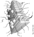
- Fig. 1 discloses a typical prior art automated storage and retrieval system 1 with a framework structure 100 and Fig. 2 and 3 discloses two different prior art container handling vehicles 201,301 suitable for operating on such a system 1.
- the framework structure 100 comprises several upright members 102 and several horizontal members 103 which are supported by the upright members 102.
- the members 102, 103 may typically be made of metal, e.g. extruded aluminium profiles.
- the framework structure 100 defines a storage grid 104 comprising storage columns 105 arranged in rows, in which storage columns 105 storage containers 106, also known as bins, are stacked one on top of another to form stacks 107.
- the storage grid 104 guards against horizontal movement of the stacks 107 of storage containers 106, and guides vertical movement of the containers 106, but does normally not otherwise support the storage containers 106 when stacked.
- the automated storage and retrieval system 1 comprises a rail system 108 arranged in a grid pattern across the top of the storage 104, on which rail system 108 a plurality of container handling vehicles 201, 301 are operated to raise storage containers 106 from, and lower storage containers 106 into, the storage columns 105, and to transport the storage containers 106 above the storage columns 105.
- the rail system 108 comprises a first set of parallel rails 110 arranged to guide movement of the container handling vehicles 201, 301 in a first direction X across the top of the frame structure 100, and a second set of parallel rails 111 arranged perpendicular to the first set of rails 110 to guide movement of the container handling vehicles 201, 301 in a second direction Y which is perpendicular to the first direction X.
- the rail system 108 defines grid columns 115 above which the container handling vehicles 201, 301 can move laterally above the storage columns 105, i.e. in a plane which is parallel to the horizontal X-Y plane.
- Each prior art container handling vehicle 201, 301 comprises a vehicle body 201a, 301a, and first and second sets of wheels 201b, 301b, 201c, 301c which enable the lateral movement of the container handling vehicles 201, 301 in the X direction and in the Y direction, respectively.
- first and second sets of wheels 201b, 301b, 201c, 301c which enable the lateral movement of the container handling vehicles 201, 301 in the X direction and in the Y direction, respectively.
- the first set of wheels 201b, 301b is arranged to engage with two adjacent rails of the first set 110 of rails
- the second set of wheels 201c, 301c is arranged to engage with two adjacent rails of the second set 111 of rails.
- Each set of wheels 201b, 301b, 201c, 301c can be lifted and lowered, so that the first set of wheels 201b, 301b and/or the second set of wheels 201c, 301c can be engaged with the respective set of rails 110, 111 at any one time.
- Each prior art container handling vehicle 201, 301 also comprises a lifting device (not shown) for vertical transportation of storage containers 106, e.g. raising a storage container 106 from, and lowering a storage container 106 into, a storage column 105.
- the lifting device comprises one or more gripping / engaging devices (not shown) which are adapted to engage a storage container 106, and which gripping / engaging devices can be lowered from the vehicle 201, 301 so that the position of the gripping / engaging devices with respect to the vehicle 201, 301 can be adjusted in a third direction Z which is orthogonal the first direction X and the second direction Y.
- Each prior art container handling vehicle 201, 301 comprises a storage compartment or space for receiving and stowing a storage container 106 when transporting the storage container 106 across the rail system 108.
- the storage space may comprise a cavity arranged centrally within the vehicle body 201a as shown in Fig. 2 and as described in e.g. WO2015/193278A1 , the contents of which are incorporated herein by reference.
- Fig. 3 shows an alternative configuration of a container handling vehicle 301 with a cantilever construction.
- a container handling vehicle 301 with a cantilever construction.
- Such a vehicle is described in detail in e.g. NO317366, the contents of which are also incorporated herein by reference.
- the central cavity container handling vehicles 201 shown in Fig. 2 may have a footprint that covers an area with dimensions in the X and Y directions which is generally equal to the lateral extent of a grid column 115, i.e. the extent of a grid column 115 in the X and Y directions, e.g. as is described in WO2015/193278A1 , the contents of which are incorporated herein by reference.
- the term 'lateral' used herein may mean 'horizontal'.
- the central cavity container handling vehicles 101 may have a footprint which is larger than the lateral area defined by a grid column 115, e.g. as is disclosed in WO2014/090684A1 .
- neighbouring grid cells are arranged in contact with each other such that there is no space there-between.
- a grid 104 In a storage grid 104, most of the grid columns 115 are storage columns 105, i.e. grid columns 105 where storage containers 106 are stored in stacks 107.
- a grid 104 normally has at least one grid column 115 which is used not for storing storage containers 106, but which comprises a location where the container handling vehicles 201, 301 can drop off and/or pick up storage containers 106 so that they can be transported to an access station (not shown) where the storage containers 106 can be accessed from outside of the grid 104 or transferred out of or into the grid 104.
- such a location is normally referred to as a 'port' and the grid column 115 in which the port is located may be referred to as a ⁇ port column' 119, 120.
- the transportation to the access station may be in any direction, that is horizontal, tilted and/or vertical.
- the storage containers 106 may be placed in a random or dedicated grid column 115 within the storage grid 104, then picked up by any container handling vehicle and transported to a port 119, 120 for further transportation to an access station.
- the term 'tilted' means transportation of storage containers 106 having a general transportation orientation somewhere between horizontal and vertical.
- one of the container handling vehicles 201, 301 is instructed to retrieve the target storage container 106 from its position in the grid 104 and transport it to the drop-off port 119.
- This operation involves moving the container handling vehicle 201, 301 to a grid location above the storage column 105 in which the target storage container 106 is positioned, retrieving the storage container 106 from the storage column 105 using the container handling vehicle's 201, 301 lifting devices (not shown), and transporting the storage container 106 to the drop-off port 119. If the target storage container 106 is located deep within a stack 107, i.e.
- the operation also involves temporarily moving the above-positioned storage containers 106 prior to lifting the target storage container 106 from the storage column 105.
- This step which is sometimes referred to as "digging" within the art, may be performed with the same container handling vehicle that is subsequently used for transporting the target storage container 106 to the drop-off port 119, or with one or a plurality of other cooperating container handling vehicles.
- the automated storage and retrieval system 1 may have container handling vehicles specifically dedicated to the task of temporarily removing storage containers 106 from a storage column 105. Once the target storage container 106 has been removed from the storage column 105, the temporarily removed storage containers 106 can be repositioned into the original storage column 105. However, the removed storage containers 106 may alternatively be relocated to other storage columns.
- one of the container handling vehicles 201, 301 is instructed to pick up the storage container 106 from the pick-up port 120 and transport it to a grid location above the storage column 105 where it is to be stored. After any storage containers 106 positioned at or above the target position within the storage column stack 107 have been removed, the container handling vehicle 201, 301 positions the storage container 106 at the desired position. The removed storage containers 106 may then be lowered back into the storage column 105 or relocated to other storage columns.
- US 20190232925 A1 describes a storage system including a charging station assembly for charging a plurality of power sources and a method thereof.
- the charging station assembly includes a charging station support fixing the charging station assembly to a base of the storage system, a plurality of charging stations, each charging station including a charger that charges the plurality of power sources and a power source transport device enabling relocation of the power source between an operational position on a remotely operated vehicle and a charging position in or at any one of the plurality of charging stations.
- EP 3505387 A1 describes a station for charging, battery swapping and energy storage comprising: a battery swapping device configured to replace a battery for an electric vehicle; a quick-swap battery pack for storing electric energy; a charging and discharging device configured to charge the quick-swap battery pack by a power grid and discharging the quick-swap battery pack to the power grid; and a monitoring system for monitoring an overall operating condition of the station and power consumption peaks and valleys of the power grid as well as controlling the battery swapping device to replace the quick-swap battery pack and controlling the charging or discharging of the charging and discharging device.
- US 20040130292 A1 describes a charging system for simultaneously charging the batteries of a plurality of battery powered vehicles.
- the charging includes one or more DC-DC power converters having one or more charging ports configured to plug into the batteries.
- the DC-DC power converters are each configured to selectively connect to more than one charging port to selectively provide for higher port power levels.
- the DC-DC power converters connect to an AC rectifier through a DC bus.
- the AC rectifier connects to an AC power source having a limited power rating.
- the AC charging system also has a controller that controls the operation of the DC-DC power converters such that the total power draw on the AC rectifier does not exceed the power rating.
- the system is further configured such that the DC-DC power converters can drain selected batteries to obtain power for charging other batteries, thus allowing for batteries to be cycled.
- EP 2889176 A1 describes a battery exchange station and a method of operating the battery exchange station.
- the battery exchange station and the method of operating the battery exchange station allow for utilization of electricity stored in a battery and improve a system's operation and electricity demand conditions by charging a large-capacity battery with electricity coming from the system and providing the electricity stored in the large-capacity battery to the system.
- EP 2496436 A0 describes a charging system for electric vehicles.
- the charging system comprises a grid power stage comprising an AC/DC inverter that can be connected on an input side via a connection point to an alternating current grid, a control device for monitoring a charging process, and at least one charging connection on an output side, the latter being able to be temporarily connected to a vehicle battery.
- the automated storage and retrieval system 1 For monitoring and controlling the automated storage and retrieval system 1, e.g. monitoring and controlling the location of respective storage containers 106 within the grid 104, the content of each storage container 106; and the movement of the container handling vehicles 201, 301 so that a desired storage container 106 can be delivered to the desired location at the desired time without the container handling vehicles 201, 301 colliding with each other, the automated storage and retrieval system 1 comprises a control system which typically is computerized and which typically comprises a database for keeping track of the storage containers 106.
- the present invention relates to a system for power management of an automated storage and retrieval system
- a system for power management of an automated storage and retrieval system comprising a plurality of container handling vehicles with at least one exchangeable and rechargeable power source for handling containers in a three dimensional underlying storage grid, a charging device for charging or drawing power from the at least one exchangeable and rechargeable power source, a power source for supplying power to the automated storage and retrieval system, and the charging device a monitoring system for monitoring energy prices, a power manager, wherein said monitoring system is configured to continuously update a the power manager with energy prices, and the power manager is configured to be updated with information regarding the level of charge of the rechargeable power sources and current resources in terms of the capacity and usage requirements of the container handling vehicles, and said power manager is configured to adjust a power strategy of the automated storage and retrieval system according to the energy prices and to control the stored energy from the rechargeable power sources via the charging devices as an additional power source for the automated storage and retrieval system during periods of high energy cost.
- the power manager is configured to control charging of the rechargeable power source(s) during periods of low energy cost and to control the stored energy as an additional power source for the storage system during periods of high energy cost and to use a ranking system to decide in which order to charge two or more rechargeable power sources and to control storing of energy.
- the monitoring system monitors present and upcoming energy prices.
- the power source can receive power via locally generated energy from renewable energy sources and/or grid power.
- the ranking system of the power manager is configured to decide to charge the rechargeable power sources with the highest charging level first and to decide to use the rechargeable power sources with the highest charging level as an additional power source first.
- the charging device can be a charging station or a charging robot, and at least one large capacity battery can be used for storing energy during periods of low energy cost.
- the present invention relates to a method for power management of an automated storage and retrieval system comprising: a plurality of container handling vehicles, with at least one exchangeable and rechargeable power source for handling containers in a three-dimensional underlying storage grid, a charging device for charging or drawing power from the at least one exchangeable and rechargeable power source, a power source for supplying power to the automated storage and retrieval system, and the charging device a monitoring system for monitoring energy prices, a power manager,
- the method comprises the following steps: letting the monitoring system establish external power information by: reading present power consumption, and updating present and upcoming energy cost,letting the monitoring system establish internal power information by: acquiring the current energy state of the automated storage and retrieval system, and estimating the future energy state of the automated storage and retrieval system, letting the power manager update the power strategy of the system according to the external and internal power information, letting the power manager control use of stored energy from the rechargeable power sources via the charging devices as an additional power source for the automated storage and retrieval system during periods of high energy cost.
- the power strategy of the system may be updated by letting the power manager use a ranking system to decide in which order to charge the rechargeable power sources and/or letting the ranking system of the power manager decide to charge the rechargeable power sources with the highest charging level first and/or letting the ranking system of the power manager decide to use the rechargeable power sources with the highest charging level as an additional power source first.
- the rechargeable power sources may be used as an additional power source for the system when the prices are high. This additional power source allows the storage system to store power when prices are low and use the stored power when prices are high.
- a power manager that controls the flow of power to or from the rechargeable power sources, the cost of operating the storage system can be reduced greatly and the problem with the operation cost of an automated storage system can be solved.
- the container handling vehicle rail system 108 allows the container handling vehicles 201 to move horizontally between different grid locations, where each grid location is associated with a grid cell 122.
- the storage grid 104 is shown with a height of eight grid cells 122. It is understood, however, that the storage grid 104 can in principle be of any size.
- the storage grid 104 can be considerably wider and/or longer than disclosed in fig. 1 .
- the grid 104 may have a horizontal extent of more than 700x700 storage columns 105.
- the grid 104 can be considerably deeper than disclosed in fig. 1 .
- the storage grid 104 may be more than twelve grid cells 122 deep, i.e. in the Z direction indicated in Fig. 1 .
- Fig. 2 is a perspective view of a prior art container handling vehicle having a centrally arranged cavity for containing storage containers 106 therein.
- the central cavity container handling vehicles 201 may have a footprint that covers an area with dimensions in the X and Y directions which is generally equal to the lateral extent of a grid column 115, i.e. the extent of a grid column 115 in the X and Y directions, e.g. as is described in WO2015/193278A1 , the contents of which are incorporated herein by reference.
- the central cavity container handling vehicles 101 may have a footprint which is larger than the lateral area defined by a grid column 115, e.g. as is disclosed in WO2014/090684A1 .
- Figure 3 is a perspective view of a prior art container handling vehicle having a cantilever for containing storage containers 106 underneath.
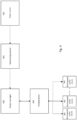
- FIG. 4 is a box drawing of the different modules of the present invention and how they are connected.
- the storage system receives power from at least one power source 401.
- the power source 401 can be either grid power or locally generated power from renewable power sources. Power can further be stored in rechargeable power sources comprised in the system.
- the storage system 1 receives both grid power and locally generated power from renewable power sources. Locally generated power from renewable power sources can be wind power, hydro power, solar power or any other power source that is available.
- the amount of available power and the cost of the power is monitored by a monitoring system 402.
- the monitoring system 402 can receive power information about available power and current cost of power from the grid provider, as well as an estimate of costs of power for an upcoming time period. The upcoming time period may for instance be the next 24 hours or even further ahead in time.
- the monitoring system 402 sends the power information to a power manager 403.
- the power manager 403 controls how the power required for the operation of the system is distributed and how much power should be drawn from the grid power, how much should be drawn from the locally generated power from renewable power sources and/or how much power should be drawn from the power stored in rechargeable power sources of the system.
- the power manager also controls if grid power or power from renewable power sources should be used for charging the rechargeable power sources.
- the power manager 403 is in control of at least one charging device 404,
- the charging device 404 is used to charge at least one rechargeable power source 405.
- rechargeable power sources 405 can be batteries used for powering the container handling vehicles 200, 300.
- the rechargeable power sources 405 can be battery packs, whose sole purpose is to store energy when the conditions are right for the locally generated renewable power sources to produce a surplus of energy and when the prices for grid power are low.
- the charging device 404 can both charge the rechargeable power sources 405 and draw power from the rechargeable power sources 405.
- the power is directed to the charging devices 404 from either the power grid and/or the locally renewable power sources.
- the power manager 403 can control the distribution of the power e.g. that some energy is stored for later use, some energy is used for charging rechargeable power sources 405 of the container handling vehicles 200, 300 and some energy is used to operate the rest of the system.
- the stored power can be directed from the rechargeable power sources 405 via the charging devices 404 to power the rest of the storage system.
- Figure 5 is a flow chart showing the different steps of the method according to a preferred embodiment of the present invention.
- the storage system first retrieves external power information 510. This requires retrieving information of the current energy supply 520 and updating the estimate for the future cost of energy 530.
- the first step is to check if there is locally generated renewable energy available 522.
- the amount of available energy from a locally generated energy source is retrieved 524.
- the next step is to retrieve information of the prices for grid power 526. This can be obtained via e.g. downloading information from the internet.
- the next step is to estimate future energy cost 530. If the system is connected to a locally generated renewable energy source 532 the future energy production from this source is estimated 534. This is done by collecting information like weather data, time of day and which season it is in order to estimate the available amount of future energy from the locally generated renewable energy source. Further, the predicted prices for the future grid energy is retrieved and updated 536.
- the next step is to retrieve internal power information 540.
- Retrieving the internal power information 540 comprises the step of calculating the systems current energy state 550.
- the current energy state can comprise information regarding how much energy that is stored in the system at the current time. Information regarding the current energy consumption of the system is also retrieved. The current consumption depends on how many container handling vehicles are operating, how many rechargeable power sources are charging in the charging devices and how much energy is consumed by the rest of the system, e.g. by the ports, conveyer belts and such.
- Retrieving the internal power information also involves the step of updating the estimate for the systems future energy state 560. This comprises estimation of the energy need for the current and upcoming activities. Further the historical data can be used in order to improve the estimates. The historical data can be used in machine learning and in artificial intelligence in order to improve the accuracy of the estimated future power consumption.
- the final step is to update the power strategy 570.
- the updating of the power strategy 570 involves a first step 580 of updating the retrieved power information, both internal 540 and external 510, and the energy need, and using historical data to optimize the charging strategy of the power manager 403.
- Updating the power strategy finally involves planning the future energy state of the system 590. If the cost of energy is low, or there is high production of locally generated renewable energy, the power manager will try to increase the stored energy in the system by charging the rechargeable energy sources more often and for a longer period of time. This is planned in relation to the activity of the system where any reduction to operational efficiency is also minimised.
- the power manager 403 starts the process over again and the power manager is hence updated continuously by receiving or retrieving information about the energy prices, charging status of the rechargeable power sources, and the internal and external power information.
- the charging strategy can be set statically.
- the batteries can be set to charge at fixed time intervals during the day.
- the system can be set up with fixed time intervals wherein it is preferred that the storage system increases its state of charge. This will typically be favorable for businesses with a work shift where the charging of the system is set to a time of day when the energy price is at its lowest (typically evening time or night time). Another time of day when the system can be set to increase its state of charge is during lunch time. Basically, any time when the ordinary work force has a down time, it is a good time for increasing the state of charge.
- the storage of the power can be in the systems internal supply of batteries. These batteries are the ones in the container handling vehicles. They are exchangeable. In an alternative solution at least one large capacity batteries can be used for storing power, when the prices are low. They are hence not a part of the rechargeable power sources that are used to power the container handling vehicles.
Landscapes
- Engineering & Computer Science (AREA)
- Power Engineering (AREA)
- Mechanical Engineering (AREA)
- Transportation (AREA)
- Business, Economics & Management (AREA)
- Economics (AREA)
- Tourism & Hospitality (AREA)
- Health & Medical Sciences (AREA)
- Theoretical Computer Science (AREA)
- General Physics & Mathematics (AREA)
- Human Resources & Organizations (AREA)
- Marketing (AREA)
- General Business, Economics & Management (AREA)
- Strategic Management (AREA)
- Physics & Mathematics (AREA)
- Primary Health Care (AREA)
- General Health & Medical Sciences (AREA)
- Water Supply & Treatment (AREA)
- Public Health (AREA)
- Operations Research (AREA)
- Development Economics (AREA)
- Entrepreneurship & Innovation (AREA)
- Quality & Reliability (AREA)
- Charge And Discharge Circuits For Batteries Or The Like (AREA)
- Remote Monitoring And Control Of Power-Distribution Networks (AREA)
- Warehouses Or Storage Devices (AREA)
Claims (23)
- System für die Leistungsverwaltung eines automatisierten Lager- und Bereitstellungssystems (1), das Folgendes umfasst:eine Vielzahl von Containerumschlagfahrzeugen (201, 301) mit mindestens einer austauschbaren undwiederaufladbaren Energiequelle (405) zum Umschlag von Containern in einem zugrundeliegenden dreidimensionalen Lagerraster (104),eine Vorrichtung (404) zum Laden oder Entnehmen von Energie aus der mindestens einen austauschbaren und wiederaufladbaren Energiequelle (405),eine Energiequelle (401) zur Energieversorgung des automatisierten Lager- und Bereitstellungssystems (1) und der Ladevorrichtung (404),ein Überwachungssystem (402) zum Überwachen der Energiepreise undeinen Leistungsmanager (403), dadurch gekennzeichnet, dass:das Überwachungssystem (402) dafür ausgebildet ist, den Leistungsmanager (403) kontinuierlich mit Energiepreisen zu aktualisieren, undder Leistungsmanager (403) dafür ausgebildet ist, eine Leistungsstrategie des automatisierten Lager- und Bereitstellungssystems (1) in Abhängigkeit von den Energiepreisen einzustellen und mit Informationen über den Ladezustand der mindestens einen austauschbaren und wiederaufladbaren Energiequelle (405) und die aktuellen Ressourcen in Bezug auf die Kapazität und die Nutzungsanforderungen der Containerumschlagfahrzeuge (201, 301) aktualisiert zu werden,und dass der Leistungsmanager (403) dafür ausgebildet ist, die gespeicherte Energie aus der mindestens einen austauschbaren und wiederaufladbaren Energiequelle (405) über die Ladevorrichtung (404) als zusätzliche Energiequelle für das automatisierte Lager- und Bereitstellungssystem (1) in Zeiten hoher Energiekosten zu steuern.
- System nach Anspruch 1, wobei der Leistungsmanager (403) für die Steuerung des Ladens der wiederaufladbaren Energiequelle(n) (405) in Zeiten niedriger Energiekosten ausgebildet ist.
- System nach Anspruch 1 oder 2, wobei das Überwachungssystem (402) dafür ausgebildet ist, aktuelle und zukünftige Energiepreise zu überwachen.
- System nach einem der vorhergehenden Ansprüche, wobei die Energiequelle (401) Energie aus lokal erzeugten erneuerbaren Energiequellen und/oder Netzstrom empfängt.
- System nach einem der vorhergehenden Ansprüche, wobei der Leistungsmanager (403) dafür ausgebildet ist, ein Rangordnungssystem zu verwenden, um zu entscheiden, in welcher Reihenfolge zwei oder mehr wiederaufladbare Energiequellen (405) geladen werden sollen.
- System nach Anspruch 5, wobei das Rangordnungssystem des Leistungsmanagers (403) dafür ausgebildet ist, zu entscheiden, die wiederaufladbare Energiequelle (405) mit dem höchsten Ladepegel zuerst zu laden.
- System nach einem der vorhergehenden Ansprüche, wobei das Rangordnungssystem des Leistungsmanagers (403) dafür ausgebildet ist, zu entscheiden, zuerst die wiederaufladbare Energiequelle (405) mit dem höchsten Ladepegel als zusätzliche Energiequelle zu verwenden.
- System nach einem der vorhergehenden Ansprüche, wobei der Leistungsmanager (403) für die Steuerung des Speicherns von Energie ausgebildet ist, wenn die zukünftigen Energiepreise niedriger sind als der durchschnittliche Energiepreis einer vorangegangenen Zeitperiode.
- System nach einem der vorhergehenden Ansprüche, wobei Energie aus lokalen erneuerbaren Energiequellen verwendet wird, um Energie zu speichern, wenn die zukünftigen Energiepreise niedriger sind als der durchschnittliche Energiepreis eines vorangegangenen Zeitraums.
- System nach Anspruch 9, wobei Energie aus lokalen erneuerbaren Energiequellen als zusätzliche Energiequelle für das Lagersystem verwendet wird, wenn die zukünftigen Energiepreise höher sind als der durchschnittliche Energiepreis eines vorangegangenen Zeitraums.
- System nach einem der Ansprüche 8-10, wobei der vorangehende Zeitraum der vorangehende Monat ist.
- System nach einem der vorhergehenden Ansprüche, wobei die Ladevorrichtung (404) eine Ladestation oder ein Laderoboter ist.
- System nach einem der vorhergehenden Ansprüche, wobei mindestens eine Batterie mit großer Kapazität zum Speichern von Energie in Zeiten niedriger Energiekosten verwendet wird.
- Verfahren zur Leistungsverwaltung eines automatisierten Lager- und Bereitstellungssystems (1), das Folgendes umfasst: eine Vielzahl von Containerumschlagfahrzeugen (201, 301) mit mindestens einer austauschbaren und wiederaufladbaren Energiequelle (405) zum Umschlag von Containern in einem zugrundeliegenden dreidimensionalen Lagerraster (104), eine Ladevorrichtung (404) zum Laden oder Entnehmen von Energie aus der mindestens einen austauschbaren und wiederaufladbaren Energiequelle (405), eine Energiequelle (401) zur Energieversorgung des automatisierten Lager- und Bereitstellungssystems (1) und der Ladevorrichtung (404), ein Überwachungssystem (402) zum Überwachen von Energiepreisen und einen Leistungsmanager (403), wobei das Verfahren die folgenden Schritte umfasst:• das Überwachungssystem (402) externe Leistungsinformationen ermitteln zu lassen, durch:o Lesen des aktuellen Energieverbrauchs, undo Aktualisieren der aktuellen und zukünftigen Energiekosten;• das Überwachungssystem (402) interne Leistungsinformationen ermitteln zu lassen, durch:o Erfassen des aktuellen Energiezustands des automatisierten Lager- und Bereitstellungssystems, undo Abschätzen des künftigen Energiezustands des automatisierten Lager- und Bereitstellungssystems;• den Leistungsmanager (403) die Leistungsstrategie des Systems entsprechend der externen und internen Leistungsinformationen aktualisieren zu lassen; und• den Leistungsmanager (403) die Verwendung von gespeicherter Energie aus der mindestens einen austauschbaren und wiederaufladbaren Energiequelle (405) über die Ladevorrichtung (404) als zusätzliche Energiequelle für das automatisierte Lager- und Bereitstellungssystem (1) in Zeiten hoher Energiekosten steuern zu lassen.
- Verfahren nach Anspruch 14, wobei die Leistungsstrategie aktualisiert wird, indem der Leistungsmanager (403) das Laden der mindestens einen austauschbaren und wiederaufladbaren Energiequelle (405) steuert.
- Verfahren nach einem der Ansprüche 14-15, wobei die Leistungsstrategie dadurch aktualisiert wird, dass die Energiequelle (401) Energie aus lokal erzeugten erneuerbaren Energiequellen und/oder Netzstrom empfängt.
- Verfahren nach einem der Ansprüche 14-16, wobei die Leistungsstrategie dadurch aktualisiert wird, dass der Leistungsmanager (403) ein Rangordnungssystem verwendet, um zu entscheiden, in welcher Reihenfolge zwei oder mehrere der mindestens einen austauschbaren und wiederaufladbaren Energiequelle(n) geladen werden sollen.
- Verfahren nach einem der Ansprüche 17, wobei die Leistungsstrategie aktualisiert wird, indem das Rangordnungssystem des Leistungsmanagers (403) entscheidet, die wiederaufladbare Energiequelle (405) mit dem höchsten Ladezustand zuerst zu laden.
- Verfahren nach einem der Ansprüche 14-16, wobei die Leistungsstrategie aktualisiert wird, indem das Rangordnungssystem des Leistungsmanagers (403) entscheidet, zuerst die wiederaufladbare Energiequelle (405) mit dem höchsten Ladezustand als zusätzliche Energiequelle zu verwenden.
- Verfahren nach einem der Ansprüche 14-19, wobei die Leistungsstrategie dadurch aktualisiert wird, dass der Leistungsmanager (403) das Speichern von Energie steuert, wenn die zukünftigen Energiepreise niedriger sind als der durchschnittliche Energiepreis eines vorangegangenen Zeitraums.
- Verfahren nach einem der Ansprüche 14-20, wobei die Leistungsstrategie dadurch aktualisiert wird, dass Energie aus lokalen erneuerbaren Energiequellen zum Speichern von Energie verwendet wird, wenn die zukünftigen Energiepreise niedriger sind als der durchschnittliche Energiepreis eines vorangegangenen Zeitraums.
- Verfahren nach einem der Ansprüche 14-21, wobei die Leistungsstrategie dadurch aktualisiert wird, dass Energie aus lokalen erneuerbaren Energiequellen als zusätzliche Energiequelle für das Speichersystem verwendet wird, wenn die künftigen Energiepreise höher sind als der durchschnittliche Energiepreis eines vorangegangenen Zeitraums.
- Verfahren nach einem der Ansprüche 20-22, wobei der vorangehende Zeitraum der vorangehende Monat ist.
Priority Applications (1)
| Application Number | Priority Date | Filing Date | Title |
|---|---|---|---|
| EP24199340.1A EP4484213A3 (de) | 2019-09-26 | 2020-09-21 | System und verfahren zur leistungsverwaltung |
Applications Claiming Priority (2)
| Application Number | Priority Date | Filing Date | Title |
|---|---|---|---|
| NO20191163A NO345589B1 (en) | 2019-09-26 | 2019-09-26 | System and method for power management |
| PCT/EP2020/076340 WO2021058442A1 (en) | 2019-09-26 | 2020-09-21 | System and method for power management |
Related Child Applications (1)
| Application Number | Title | Priority Date | Filing Date |
|---|---|---|---|
| EP24199340.1A Division EP4484213A3 (de) | 2019-09-26 | 2020-09-21 | System und verfahren zur leistungsverwaltung |
Publications (3)
| Publication Number | Publication Date |
|---|---|
| EP4034419A1 EP4034419A1 (de) | 2022-08-03 |
| EP4034419C0 EP4034419C0 (de) | 2024-09-11 |
| EP4034419B1 true EP4034419B1 (de) | 2024-09-11 |
Family
ID=72613927
Family Applications (2)
| Application Number | Title | Priority Date | Filing Date |
|---|---|---|---|
| EP24199340.1A Pending EP4484213A3 (de) | 2019-09-26 | 2020-09-21 | System und verfahren zur leistungsverwaltung |
| EP20775864.0A Active EP4034419B1 (de) | 2019-09-26 | 2020-09-21 | System und verfahren zur leistungsverwaltung |
Family Applications Before (1)
| Application Number | Title | Priority Date | Filing Date |
|---|---|---|---|
| EP24199340.1A Pending EP4484213A3 (de) | 2019-09-26 | 2020-09-21 | System und verfahren zur leistungsverwaltung |
Country Status (10)
| Country | Link |
|---|---|
| US (2) | US12286027B2 (de) |
| EP (2) | EP4484213A3 (de) |
| JP (1) | JP2022549686A (de) |
| KR (1) | KR20220069984A (de) |
| CN (2) | CN118560326A (de) |
| CA (1) | CA3151951A1 (de) |
| ES (1) | ES2991056T3 (de) |
| NO (1) | NO345589B1 (de) |
| PL (1) | PL4034419T3 (de) |
| WO (1) | WO2021058442A1 (de) |
Families Citing this family (5)
| Publication number | Priority date | Publication date | Assignee | Title |
|---|---|---|---|---|
| US12009678B2 (en) | 2018-02-08 | 2024-06-11 | Walmart Apollo, Llc | Opportunistic charging system for an automated storage and retrieval system |
| US20230170731A1 (en) * | 2020-04-24 | 2023-06-01 | Ocado Innovation Limited | Energy storage system for a load handling device |
| GB2619064A (en) * | 2022-05-26 | 2023-11-29 | Ocado Innovation Ltd | A combined power and data unit for a storage and retreival system, and related devices |
| FR3139810B1 (fr) | 2022-09-20 | 2025-10-10 | Exotec | Méthode et système pour la gestion d’énergie dans un système de stockage et de récupération automatisé |
| DE102022126609A1 (de) * | 2022-10-12 | 2024-04-18 | Bayerische Motoren Werke Aktiengesellschaft | Laden eines Elektrofahrzeugs an einem Ladepunkt einer Liegenschaft |
Citations (1)
| Publication number | Priority date | Publication date | Assignee | Title |
|---|---|---|---|---|
| EP2496436B1 (de) * | 2009-11-05 | 2018-04-18 | Daniel Schneider | Ladesystem für elektrofahrzeuge |
Family Cites Families (26)
| Publication number | Priority date | Publication date | Assignee | Title |
|---|---|---|---|---|
| JPH09124106A (ja) * | 1995-11-02 | 1997-05-13 | Daifuku Co Ltd | 自動倉庫設備 |
| NO317366B1 (no) | 1999-07-01 | 2004-10-18 | Autostore As | Lagringsanlegg med fjernstyrte vogner med to hjulsett og heisinnretning for drift på skinner anlagt i kryss over kolonner av lagringsenheter som er adskilt med vertikale profilstolper |
| US7256516B2 (en) * | 2000-06-14 | 2007-08-14 | Aerovironment Inc. | Battery charging system and method |
| US20100017045A1 (en) * | 2007-11-30 | 2010-01-21 | Johnson Controls Technology Company | Electrical demand response using energy storage in vehicles and buildings |
| US20100292855A1 (en) * | 2009-05-14 | 2010-11-18 | Michael Kintner-Meyer | Battery Charging Control Methods, Electrical Vehicle Charging Methods, Battery Charging Control Apparatus, and Electrical Vehicles |
| KR101132948B1 (ko) * | 2010-05-13 | 2012-04-05 | 엘에스산전 주식회사 | 전기자동차 충방전 시스템, 충방전 장치, 충방전 방법 |
| JP2012075247A (ja) * | 2010-09-28 | 2012-04-12 | Kddi Corp | 制御プログラム、充電最適制御装置および駐車場システム |
| EP2634034A4 (de) * | 2010-10-26 | 2015-07-29 | Toyota Motor Co Ltd | Stromversorgungsvorrichtung, fahrzeug damit und stromversorgungsverfahren |
| NO335839B1 (no) | 2012-12-10 | 2015-03-02 | Jakob Hatteland Logistics As | Robot for transport av lagringsbeholdere |
| JP6125843B2 (ja) * | 2013-01-18 | 2017-05-10 | 京セラ株式会社 | 電力制御装置、電力制御システム、および電力制御方法 |
| KR101528079B1 (ko) * | 2013-12-27 | 2015-06-10 | 두산중공업 주식회사 | 배터리 교환 스테이션 및 배터리 교환 스테이션의 운영 방법 |
| NO340313B1 (no) * | 2014-01-08 | 2017-03-27 | Jakob Hatteland Logistics As | Fjernstyrt kjøretøy for å plukke opp lagringsbeholdere fra et lagringssystem, lagringssystem for lagring av beholdere og fremgangsmåte for å bytte en strømkilde |
| JPWO2015129301A1 (ja) | 2014-02-26 | 2017-03-30 | 日本電気株式会社 | マイクログリッドシステムおよびその制御方法 |
| NO337544B1 (no) | 2014-06-19 | 2016-05-02 | Jakob Hatteland Logistics As | Fjernstyrt kjøretøysammenstilling for å plukke opp lagringsbeholdere fra et lagringssystem |
| US10017068B2 (en) * | 2014-06-19 | 2018-07-10 | Proterra Inc. | Charging of a fleet of electric vehicles |
| NO340577B1 (en) * | 2015-09-04 | 2017-05-15 | Jakob Hatteland Logistics As | Method for fetching a target bin stored in a storage system and a storage system which includes a control device operating in accordance with the method |
| JP7163001B2 (ja) * | 2016-03-03 | 2022-10-31 | 三菱重工業株式会社 | 電力マネジメント装置及び電力マネジメント方法並びにロジスティクスネットワークシステム |
| US10011183B2 (en) * | 2016-03-09 | 2018-07-03 | Toyota Jidosha Kabushiki Kaisha | Optimized charging and discharging of a plug-in electric vehicle |
| US10454277B2 (en) * | 2016-06-08 | 2019-10-22 | Faith Technologies, Inc. | Method and apparatus for controlling power flow in a hybrid power system |
| NO344308B1 (en) | 2016-06-21 | 2019-10-28 | Autostore Tech As | Storage system comprising a charging station assembly and method of replacing the power source of a remotely operated vehicle |
| CN205970910U (zh) * | 2016-08-25 | 2017-02-22 | 上海蔚来汽车有限公司 | 紧凑型分布式充换储电站 |
| CN106773715B (zh) * | 2017-01-19 | 2023-08-01 | 上海定势能源有限公司 | 基于电力现货价格预测与跟踪的储能运行控制方法及系统 |
| CN111491825B (zh) * | 2017-12-18 | 2025-08-12 | 福特全球技术公司 | 使电动车辆排队以提高车队可用性 |
| WO2019126806A1 (en) * | 2017-12-22 | 2019-06-27 | The Regents Of The University Of California | Design and control of electric vehicle charging infrastructure |
| CN109685554A (zh) * | 2018-12-13 | 2019-04-26 | 江苏中科瀚星数据科技有限公司 | 一种居民区电动汽车充电桩运营模式 |
| EP3767559B1 (de) * | 2019-07-14 | 2023-11-15 | IMEC vzw | Mehrskaliger optimierungsrahmen für intelligente energiesysteme |
-
2019
- 2019-09-26 NO NO20191163A patent/NO345589B1/en unknown
-
2020
- 2020-09-21 CN CN202410618294.8A patent/CN118560326A/zh active Pending
- 2020-09-21 PL PL20775864.0T patent/PL4034419T3/pl unknown
- 2020-09-21 CN CN202080067348.6A patent/CN114450190B/zh active Active
- 2020-09-21 WO PCT/EP2020/076340 patent/WO2021058442A1/en not_active Ceased
- 2020-09-21 KR KR1020227013368A patent/KR20220069984A/ko active Pending
- 2020-09-21 US US17/754,182 patent/US12286027B2/en active Active
- 2020-09-21 CA CA3151951A patent/CA3151951A1/en active Pending
- 2020-09-21 EP EP24199340.1A patent/EP4484213A3/de active Pending
- 2020-09-21 ES ES20775864T patent/ES2991056T3/es active Active
- 2020-09-21 JP JP2022519212A patent/JP2022549686A/ja active Pending
- 2020-09-21 EP EP20775864.0A patent/EP4034419B1/de active Active
-
2025
- 2025-02-27 US US19/065,994 patent/US20250242711A1/en active Pending
Patent Citations (1)
| Publication number | Priority date | Publication date | Assignee | Title |
|---|---|---|---|---|
| EP2496436B1 (de) * | 2009-11-05 | 2018-04-18 | Daniel Schneider | Ladesystem für elektrofahrzeuge |
Also Published As
| Publication number | Publication date |
|---|---|
| CN114450190B (zh) | 2024-05-14 |
| NO345589B1 (en) | 2021-05-03 |
| CN114450190A (zh) | 2022-05-06 |
| JP2022549686A (ja) | 2022-11-28 |
| US20220289063A1 (en) | 2022-09-15 |
| EP4034419C0 (de) | 2024-09-11 |
| WO2021058442A1 (en) | 2021-04-01 |
| ES2991056T3 (es) | 2024-12-02 |
| EP4034419A1 (de) | 2022-08-03 |
| KR20220069984A (ko) | 2022-05-27 |
| US20250242711A1 (en) | 2025-07-31 |
| PL4034419T3 (pl) | 2025-02-10 |
| CN118560326A (zh) | 2024-08-30 |
| EP4484213A3 (de) | 2025-07-02 |
| EP4484213A2 (de) | 2025-01-01 |
| US12286027B2 (en) | 2025-04-29 |
| NO20191163A1 (en) | 2021-03-29 |
| CA3151951A1 (en) | 2021-04-01 |
Similar Documents
| Publication | Publication Date | Title |
|---|---|---|
| EP4034419B1 (de) | System und verfahren zur leistungsverwaltung | |
| US12296718B2 (en) | System and a method for harvesting energy from a container handling vehicle | |
| CN119451855A (zh) | 存储和取回系统 | |
| EP3949068B1 (de) | Dynamische leistungsverwaltung | |
| HK40114627A (en) | System and method for power management | |
| HK40071278B (zh) | 用於电力管理的系统和方法 | |
| HK40071278A (en) | System and method for power management | |
| US20250058648A1 (en) | An automated storage and retrieval system and a method of operating such an automated storage and retrieval system | |
| JP7673631B2 (ja) | 作業システム | |
| HK40060631B (zh) | 动态电力管理 | |
| HK40060631A (en) | Dynamic power management |
Legal Events
| Date | Code | Title | Description |
|---|---|---|---|
| STAA | Information on the status of an ep patent application or granted ep patent |
Free format text: STATUS: UNKNOWN |
|
| STAA | Information on the status of an ep patent application or granted ep patent |
Free format text: STATUS: THE INTERNATIONAL PUBLICATION HAS BEEN MADE |
|
| PUAI | Public reference made under article 153(3) epc to a published international application that has entered the european phase |
Free format text: ORIGINAL CODE: 0009012 |
|
| STAA | Information on the status of an ep patent application or granted ep patent |
Free format text: STATUS: REQUEST FOR EXAMINATION WAS MADE |
|
| 17P | Request for examination filed |
Effective date: 20220421 |
|
| AK | Designated contracting states |
Kind code of ref document: A1 Designated state(s): AL AT BE BG CH CY CZ DE DK EE ES FI FR GB GR HR HU IE IS IT LI LT LU LV MC MK MT NL NO PL PT RO RS SE SI SK SM TR |
|
| DAV | Request for validation of the european patent (deleted) | ||
| DAX | Request for extension of the european patent (deleted) | ||
| STAA | Information on the status of an ep patent application or granted ep patent |
Free format text: STATUS: EXAMINATION IS IN PROGRESS |
|
| 17Q | First examination report despatched |
Effective date: 20230228 |
|
| GRAP | Despatch of communication of intention to grant a patent |
Free format text: ORIGINAL CODE: EPIDOSNIGR1 |
|
| STAA | Information on the status of an ep patent application or granted ep patent |
Free format text: STATUS: GRANT OF PATENT IS INTENDED |
|
| INTG | Intention to grant announced |
Effective date: 20230628 |
|
| GRAJ | Information related to disapproval of communication of intention to grant by the applicant or resumption of examination proceedings by the epo deleted |
Free format text: ORIGINAL CODE: EPIDOSDIGR1 |
|
| STAA | Information on the status of an ep patent application or granted ep patent |
Free format text: STATUS: EXAMINATION IS IN PROGRESS |
|
| GRAP | Despatch of communication of intention to grant a patent |
Free format text: ORIGINAL CODE: EPIDOSNIGR1 |
|
| STAA | Information on the status of an ep patent application or granted ep patent |
Free format text: STATUS: GRANT OF PATENT IS INTENDED |
|
| P01 | Opt-out of the competence of the unified patent court (upc) registered |
Effective date: 20231006 |
|
| INTC | Intention to grant announced (deleted) | ||
| INTG | Intention to grant announced |
Effective date: 20231113 |
|
| GRAJ | Information related to disapproval of communication of intention to grant by the applicant or resumption of examination proceedings by the epo deleted |
Free format text: ORIGINAL CODE: EPIDOSDIGR1 |
|
| STAA | Information on the status of an ep patent application or granted ep patent |
Free format text: STATUS: EXAMINATION IS IN PROGRESS |
|
| GRAP | Despatch of communication of intention to grant a patent |
Free format text: ORIGINAL CODE: EPIDOSNIGR1 |
|
| STAA | Information on the status of an ep patent application or granted ep patent |
Free format text: STATUS: GRANT OF PATENT IS INTENDED |
|
| INTC | Intention to grant announced (deleted) | ||
| INTG | Intention to grant announced |
Effective date: 20240417 |
|
| GRAS | Grant fee paid |
Free format text: ORIGINAL CODE: EPIDOSNIGR3 |
|
| 111L | Licence recorded |
Designated state(s): AL AT BE BG CH CY CZ DE DK EE ES FI FR GB GR HR HU IE IS IT LT LU LV MC MK MT NL NO PL PT RO RS SE SI SK SM TR Name of requester: OCADO INNOVATION LIMITED, GB Effective date: 20240515 Designated state(s): AL AT BE BG CH CY CZ DE DK EE ES FI FR GB GR HR HU IE IS IT LT LU LV MC MK MT NL NO PL PT RO RS SE SI SK SM TR Name of requester: OCADO GROUP PLC, GB Effective date: 20240515 Designated state(s): AL AT BE BG CH CY CZ DE DK EE ES FI FR GB GR HR HU IE IS IT LT LU LV MC MK MT NL NO PL PT RO RS SE SI SK SM TR Name of requester: OCADO SOLUTIONS LIMITED, GB Effective date: 20240515 |
|
| GRAA | (expected) grant |
Free format text: ORIGINAL CODE: 0009210 |
|
| STAA | Information on the status of an ep patent application or granted ep patent |
Free format text: STATUS: THE PATENT HAS BEEN GRANTED |
|
| 111L | Licence recorded |
Designated state(s): AL AT BE BG CH CY CZ DE DK EE ES FI FR GB GR HR HU IE IS IT LT LU LV MC MK MT NL NO PL PT RO RS SE SI SK SM TR Name of requester: OCADO INNOVATION LIMITED, GB Effective date: 20240515 Designated state(s): AL AT BE BG CH CY CZ DE DK EE ES FI FR GB GR HR HU IE IS IT LT LU LV MC MK MT NL NO PL PT RO RS SE SI SK SM TR Name of requester: OCADO GROUP PLC, GB Effective date: 20240515 Designated state(s): AL AT BE BG CH CY CZ DE DK EE ES FI FR GB GR HR HU IE IS IT LT LU LV MC MK MT NL NO PL PT RO RS SE SI SK SM TR Name of requester: OCADO SOLUTIONS LIMITED, GB Effective date: 20240515 |
|
| AK | Designated contracting states |
Kind code of ref document: B1 Designated state(s): AL AT BE BG CH CY CZ DE DK EE ES FI FR GB GR HR HU IE IS IT LI LT LU LV MC MK MT NL NO PL PT RO RS SE SI SK SM TR |
|
| REG | Reference to a national code |
Ref country code: GB Ref legal event code: FG4D |
|
| REG | Reference to a national code |
Ref country code: CH Ref legal event code: EP |
|
| REG | Reference to a national code |
Ref country code: DE Ref legal event code: R096 Ref document number: 602020037606 Country of ref document: DE |
|
| REG | Reference to a national code |
Ref country code: IE Ref legal event code: FG4D |
|
| U01 | Request for unitary effect filed |
Effective date: 20241011 |
|
| U07 | Unitary effect registered |
Designated state(s): AT BE BG DE DK EE FI FR IT LT LU LV MT NL PT RO SE SI Effective date: 20241029 |
|
| REG | Reference to a national code |
Ref country code: ES Ref legal event code: FG2A Ref document number: 2991056 Country of ref document: ES Kind code of ref document: T3 Effective date: 20241202 |
|
| P04 | Withdrawal of opt-out of the competence of the unified patent court (upc) registered |
Free format text: CASE NUMBER: APP_58194/2024 Effective date: 20241025 |
|
| U20 | Renewal fee for the european patent with unitary effect paid |
Year of fee payment: 5 Effective date: 20241105 |
|
| PG25 | Lapsed in a contracting state [announced via postgrant information from national office to epo] |
Ref country code: NO Free format text: LAPSE BECAUSE OF FAILURE TO SUBMIT A TRANSLATION OF THE DESCRIPTION OR TO PAY THE FEE WITHIN THE PRESCRIBED TIME-LIMIT Effective date: 20241211 |
|
| PG25 | Lapsed in a contracting state [announced via postgrant information from national office to epo] |
Ref country code: GR Free format text: LAPSE BECAUSE OF FAILURE TO SUBMIT A TRANSLATION OF THE DESCRIPTION OR TO PAY THE FEE WITHIN THE PRESCRIBED TIME-LIMIT Effective date: 20241212 |
|
| PG25 | Lapsed in a contracting state [announced via postgrant information from national office to epo] |
Ref country code: HR Free format text: LAPSE BECAUSE OF FAILURE TO SUBMIT A TRANSLATION OF THE DESCRIPTION OR TO PAY THE FEE WITHIN THE PRESCRIBED TIME-LIMIT Effective date: 20240911 |
|
| PG25 | Lapsed in a contracting state [announced via postgrant information from national office to epo] |
Ref country code: RS Free format text: LAPSE BECAUSE OF FAILURE TO SUBMIT A TRANSLATION OF THE DESCRIPTION OR TO PAY THE FEE WITHIN THE PRESCRIBED TIME-LIMIT Effective date: 20241211 |
|
| PGFP | Annual fee paid to national office [announced via postgrant information from national office to epo] |
Ref country code: ES Payment date: 20241115 Year of fee payment: 5 |
|
| PG25 | Lapsed in a contracting state [announced via postgrant information from national office to epo] |
Ref country code: RS Free format text: LAPSE BECAUSE OF FAILURE TO SUBMIT A TRANSLATION OF THE DESCRIPTION OR TO PAY THE FEE WITHIN THE PRESCRIBED TIME-LIMIT Effective date: 20241211 Ref country code: NO Free format text: LAPSE BECAUSE OF FAILURE TO SUBMIT A TRANSLATION OF THE DESCRIPTION OR TO PAY THE FEE WITHIN THE PRESCRIBED TIME-LIMIT Effective date: 20241211 Ref country code: HR Free format text: LAPSE BECAUSE OF FAILURE TO SUBMIT A TRANSLATION OF THE DESCRIPTION OR TO PAY THE FEE WITHIN THE PRESCRIBED TIME-LIMIT Effective date: 20240911 Ref country code: GR Free format text: LAPSE BECAUSE OF FAILURE TO SUBMIT A TRANSLATION OF THE DESCRIPTION OR TO PAY THE FEE WITHIN THE PRESCRIBED TIME-LIMIT Effective date: 20241212 |
|
| PGFP | Annual fee paid to national office [announced via postgrant information from national office to epo] |
Ref country code: CH Payment date: 20241118 Year of fee payment: 5 |
|
| PG25 | Lapsed in a contracting state [announced via postgrant information from national office to epo] |
Ref country code: IS Free format text: LAPSE BECAUSE OF FAILURE TO SUBMIT A TRANSLATION OF THE DESCRIPTION OR TO PAY THE FEE WITHIN THE PRESCRIBED TIME-LIMIT Effective date: 20250111 |
|
| PG25 | Lapsed in a contracting state [announced via postgrant information from national office to epo] |
Ref country code: SM Free format text: LAPSE BECAUSE OF FAILURE TO SUBMIT A TRANSLATION OF THE DESCRIPTION OR TO PAY THE FEE WITHIN THE PRESCRIBED TIME-LIMIT Effective date: 20240911 |
|
| PG25 | Lapsed in a contracting state [announced via postgrant information from national office to epo] |
Ref country code: SK Free format text: LAPSE BECAUSE OF FAILURE TO SUBMIT A TRANSLATION OF THE DESCRIPTION OR TO PAY THE FEE WITHIN THE PRESCRIBED TIME-LIMIT Effective date: 20240911 |
|
| PG25 | Lapsed in a contracting state [announced via postgrant information from national office to epo] |
Ref country code: MC Free format text: LAPSE BECAUSE OF FAILURE TO SUBMIT A TRANSLATION OF THE DESCRIPTION OR TO PAY THE FEE WITHIN THE PRESCRIBED TIME-LIMIT Effective date: 20240911 |
|
| PLBE | No opposition filed within time limit |
Free format text: ORIGINAL CODE: 0009261 |
|
| STAA | Information on the status of an ep patent application or granted ep patent |
Free format text: STATUS: NO OPPOSITION FILED WITHIN TIME LIMIT |
|
| PG25 | Lapsed in a contracting state [announced via postgrant information from national office to epo] |
Ref country code: IE Free format text: LAPSE BECAUSE OF NON-PAYMENT OF DUE FEES Effective date: 20240921 |
|
| 26N | No opposition filed |
Effective date: 20250612 |
|
| REG | Reference to a national code |
Ref country code: CH Ref legal event code: U11 Free format text: ST27 STATUS EVENT CODE: U-0-0-U10-U11 (AS PROVIDED BY THE NATIONAL OFFICE) Effective date: 20251001 |
|
| U20 | Renewal fee for the european patent with unitary effect paid |
Year of fee payment: 6 Effective date: 20250904 |
|
| PGFP | Annual fee paid to national office [announced via postgrant information from national office to epo] |
Ref country code: PL Payment date: 20250908 Year of fee payment: 6 |
|
| PGFP | Annual fee paid to national office [announced via postgrant information from national office to epo] |
Ref country code: GB Payment date: 20250904 Year of fee payment: 6 |
|
| PGFP | Annual fee paid to national office [announced via postgrant information from national office to epo] |
Ref country code: CZ Payment date: 20250911 Year of fee payment: 6 |