EP4033749B1 - Frontbilderzeugungsvorrichtung für schwermaschinen - Google Patents
Frontbilderzeugungsvorrichtung für schwermaschinen Download PDFInfo
- Publication number
- EP4033749B1 EP4033749B1 EP20865024.2A EP20865024A EP4033749B1 EP 4033749 B1 EP4033749 B1 EP 4033749B1 EP 20865024 A EP20865024 A EP 20865024A EP 4033749 B1 EP4033749 B1 EP 4033749B1
- Authority
- EP
- European Patent Office
- Prior art keywords
- image
- front image
- projection
- images
- image processor
- Prior art date
- Legal status (The legal status is an assumption and is not a legal conclusion. Google has not performed a legal analysis and makes no representation as to the accuracy of the status listed.)
- Active
Links
Images


Classifications
-
- H—ELECTRICITY
- H04—ELECTRIC COMMUNICATION TECHNIQUE
- H04N—PICTORIAL COMMUNICATION, e.g. TELEVISION
- H04N5/00—Details of television systems
- H04N5/222—Studio circuitry; Studio devices; Studio equipment
- H04N5/262—Studio circuits, e.g. for mixing, switching-over, change of character of image, other special effects ; Cameras specially adapted for the electronic generation of special effects
- H04N5/2624—Studio circuits, e.g. for mixing, switching-over, change of character of image, other special effects ; Cameras specially adapted for the electronic generation of special effects for obtaining an image which is composed of whole input images, e.g. splitscreen
-
- E—FIXED CONSTRUCTIONS
- E02—HYDRAULIC ENGINEERING; FOUNDATIONS; SOIL SHIFTING
- E02F—DREDGING; SOIL-SHIFTING
- E02F9/00—Component parts of dredgers or soil-shifting machines, not restricted to one of the kinds covered by groups E02F3/00 - E02F7/00
- E02F9/26—Indicating devices
- E02F9/261—Surveying the work-site to be treated
-
- E—FIXED CONSTRUCTIONS
- E02—HYDRAULIC ENGINEERING; FOUNDATIONS; SOIL SHIFTING
- E02F—DREDGING; SOIL-SHIFTING
- E02F9/00—Component parts of dredgers or soil-shifting machines, not restricted to one of the kinds covered by groups E02F3/00 - E02F7/00
- E02F9/26—Indicating devices
- E02F9/264—Sensors and their calibration for indicating the position of the work tool
-
- H—ELECTRICITY
- H04—ELECTRIC COMMUNICATION TECHNIQUE
- H04N—PICTORIAL COMMUNICATION, e.g. TELEVISION
- H04N23/00—Cameras or camera modules comprising electronic image sensors; Control thereof
- H04N23/50—Constructional details
- H04N23/555—Constructional details for picking-up images in sites, inaccessible due to their dimensions or hazardous conditions, e.g. endoscopes or borescopes
-
- H—ELECTRICITY
- H04—ELECTRIC COMMUNICATION TECHNIQUE
- H04N—PICTORIAL COMMUNICATION, e.g. TELEVISION
- H04N23/00—Cameras or camera modules comprising electronic image sensors; Control thereof
- H04N23/57—Mechanical or electrical details of cameras or camera modules specially adapted for being embedded in other devices
-
- H—ELECTRICITY
- H04—ELECTRIC COMMUNICATION TECHNIQUE
- H04N—PICTORIAL COMMUNICATION, e.g. TELEVISION
- H04N23/00—Cameras or camera modules comprising electronic image sensors; Control thereof
- H04N23/60—Control of cameras or camera modules
- H04N23/698—Control of cameras or camera modules for achieving an enlarged field of view, e.g. panoramic image capture
-
- H—ELECTRICITY
- H04—ELECTRIC COMMUNICATION TECHNIQUE
- H04N—PICTORIAL COMMUNICATION, e.g. TELEVISION
- H04N23/00—Cameras or camera modules comprising electronic image sensors; Control thereof
- H04N23/90—Arrangement of cameras or camera modules, e.g. multiple cameras in TV studios or sports stadiums
-
- H—ELECTRICITY
- H04—ELECTRIC COMMUNICATION TECHNIQUE
- H04N—PICTORIAL COMMUNICATION, e.g. TELEVISION
- H04N5/00—Details of television systems
- H04N5/222—Studio circuitry; Studio devices; Studio equipment
- H04N5/262—Studio circuits, e.g. for mixing, switching-over, change of character of image, other special effects ; Cameras specially adapted for the electronic generation of special effects
- H04N5/2628—Alteration of picture size, shape, position or orientation, e.g. zooming, rotation, rolling, perspective, translation
-
- H—ELECTRICITY
- H04—ELECTRIC COMMUNICATION TECHNIQUE
- H04N—PICTORIAL COMMUNICATION, e.g. TELEVISION
- H04N5/00—Details of television systems
- H04N5/222—Studio circuitry; Studio devices; Studio equipment
- H04N5/262—Studio circuits, e.g. for mixing, switching-over, change of character of image, other special effects ; Cameras specially adapted for the electronic generation of special effects
- H04N5/265—Mixing
Definitions
- the present disclosure relates to a front image generation device for heavy equipment, and more particularly, to a front image generation device for heavy equipment, which generates a front image for securing a front view in heavy equipment such as a wheel loader in which it is difficult to check a front area during a work.
- Heavy equipment is used for various works in construction sites, and may include a wheel loader, an excavator and the like, for example.
- a large-sized part is disposed in front of a driver in the heavy equipment.
- the driver's front view is blocked by the large-sized part.
- a driver's front view is blocked by a bucket which is lifted/lowered at the front of the wheel loader.
- EP 3 342 942 A1 discloses a control system for a work vehicle, and in particular describes extracting a perspective image based on image data (ICDT) acquired through a camera.
- ICDT image data
- KR 2013 0069912 A discloses an apparatus for displaying operation guide information of construction equipment.
- US 2016/344931 A1 discloses a monitoring image display device of an industrial machine.
- US 2016/217331 A1 discloses a monitoring image display device of an industrial machine.
- US 2016/344931 A1 discloses an imaging system for generating a surround-view image.
- US 2016/301864 discloses an imaging processing system for generating a surround-view image.
- the present disclosure is proposed to solve the above conventional problem, and an object of the present disclosure is to provide a front image generation device for heavy equipment, which generates a front image of heavy equipment by compositing images taken by a plurality of cameras disposed on the heavy equipment.
- a front image generation device for heavy equipment which generates a composite front image by using two or more cameras, according to an exemplary embodiment of the present disclosure includes: an upper camera disposed on a wheel loader and configured to generate a first front image; a lower camera disposed on the wheel loader and configured to generate a second front image; an image processor configured to generate a composite front image by compositing the first front image and the second front image; and a display configured to display the composite front image generated by the image processor.
- the image processor may generate a composite front image by compositing the first and second front images, compositing a part of the second front image into the first front image, or compositing a part of the first front image into the second front image. At this time, the image processor may generate the composite front image in which the bucket of the wheel loader is translucently represented.
- the image processor may receive the position of a bucket from an external sensor, or detect the position of the bucket of the wheel loader through image processing, and then may set different weights to the first and second front images, depending on the position of the bucket of the wheel loader. When the bucket is located at the bottom, the image processor may set a higher weight than the second front image to the first front image, and when the bucket is located at the top, the image processor may set a higher weight than the first front image to the second front image.
- the image processor may generate the composite front image in which a common area between the first and second front images is represented more brightly than the other area, and the bucket is represented in an opaque state until the bucket blocks the target, and represented in a translucent or transparent state from the point of time that the bucket blocks the target.
- the image processor In order to generate the composite front image, the image processor needs to set a projection plane (or projection space), and composite images taken by a plurality of cameras onto the set projection plane.
- the image processor may set the projection plane by checking distance information and posture information on the basis of information acquired from various sensors, a controller and the like.
- the image processor may set the projection plane by analyzing feature points of the taken front images, or analyzing curved surface information of the taken front images.
- the image processor may set the projection plane by combining two or more of such methods.
- the image processor needs to convert the luminance, transparency, or brightness of all or part of each of the images and composite the images, when or after projecting the images taken by the plurality of cameras onto a preset projection plane or projection space, in order to minimize a sense of difference in the composite front image.
- the image processor may set a plane at the predetermined distance to a projection plane, and project (convert) camera images at an angle corresponding to the projection plane, such that images taken by a plurality of cameras are matched with one another on the projection plane.
- the image processor may divide an image into areas occupied by the respective objects, and perform a composition operation on a projection plane set to the distance to the object corresponding to each of the divided areas, in order to generate a composite front image. Furthermore, when a plurality of objects are located at different distances, the image processor may aggregate distance information to the respective objects, set a 3D projection plane on this information, and composite images taken with respect to projection planes of the 3D projection plane, thereby generating a composite front image.
- the projection plane may include a 3D projection plane.
- the image processor may generate the projection plane through a method of extracting feature points of images taken by a plurality of cameras, extracting matched feature points by evaluating the coincidence for the same object, and optimizing the projection plane by matching the matched feature points with each other, and then generate a composite front image.
- this method is used, the plurality of images are matched and composited while portions of the images are extended or reduced.
- the process of extracting and matching the feature points may bear a burden on the image processor.
- the image processor may set feature points in images taken by a plurality of cameras in advance, and set information on how the set feature points are matched in the respective images.
- the image processor may generate a composite front image such that the matched feature points in the images taken by the respective cameras coincide with each other on the basis of the feature points of the respective images. Therefore, the front images are composited while portions of the images are extended or reduced. Since the feature points and the matching information are set in advance, the burden on the image processor may be reduced, and distortions of the respective images taken by the plurality of cameras may be partially adjusted to generate the composite front image.
- An example in which matching points are set in the respective images will be described below with reference to FIGS. 11 and 12 .
- the image processor may convert the first front image and the second front image into a first projection image and a second projection image on the basis of distance information, and generate a composite front image by compositing the first and second projection images.
- the image processor may set a plurality of random distances, convert the first front image and the second front image into first projection images and second projection images on the basis of the respective random distances, calculates the coincidences between the first projection images and the second projection images at the respective random distances, and set the random distance, at which the highest coincidence is detected, to distance information, or utilize distance information inputted from the outside. At this time, when the position of the wheel loader is changed, the image processor may reset the distance information.
- the image processor may divide the first front image into a plurality of areas, and generate a first projection image by converting the plurality of areas into a projection image on the basis of different pieces of distance information for the respective areas. Furthermore, the image processor may divide the second front image into a plurality of areas, and generate a second projection image by converting the plurality of areas into a projection image on the basis of different pieces of distance information for the respective areas.
- the image processor may utilize distance information inputted from the outside, set distance information on the basis of the feature points set in the first and second front images, and detect areas, which are used for composition, from the first and second front images on the basis of the feature points set in the first and second front images.
- the front image generation device for heavy equipment may composite front images taken at the top and bottom of a wheel loader, and display the composite front image, thereby minimizing a blind zone formed by a bucket of the wheel loader.
- the front image generation device for heavy equipment may translucently display the bucket in the composite front image, thereby preventing a driver's front view from being blocked by the bucket.
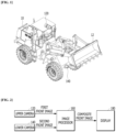
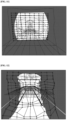
- a front image generation device for heavy equipment in accordance with an embodiment of the present disclosure is a device for generating a front image of a wheel loader 10, and includes an upper camera 120 disposed at the top of the wheel loader 10 and a lower camera 140 disposed at the bottom of the wheel loader 10.
- the upper camera 120 is disposed on the roof of a driver seat in the wheel loader 10
- the lower camera 140 is disposed at the front bottom of a vehicle body of the wheel loader 10.
- FIG. 1 illustrates that the upper camera 120 and the lower camera 140 are disposed at the top and bottom of the wheel loader 10.
- the present disclosure is not limited thereto, but the upper camera 120 and the lower camera 140 may be disposed at any positions where the cameras can take front images.
- the following descriptions will be focused on two cameras, i.e. the upper camera 120 and the lower camera 140.
- the present disclosure is not limited thereto, but it should be interpreted that three or more cameras may be used to generate an image.
- two or more cameras mounted in front of a driver seat may be combined with the upper camera 120 and the lower camera 140, in order to composite images.
- any cameras such as a camera mounted on an arm or bucket may be utilized to composite images, as long as the cameras can each take even a part of a front image.
- the upper camera 120 generates a first front image by taking an image of a front area of the wheel loader 10 from the top of the wheel loader 10
- the lower camera 140 generates a second front image by taking an image of the front area of the wheel loader 10 from the bottom of the wheel loader 10.
- the front image generation device for heavy equipment further includes an image processor 160 configured to generate a composite front image by compositing the first and second front images, and a display 180 configured to display the composite front image provided by the image processor 160.
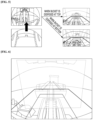
- the image processor 160 generates a composite front image by compositing the images taken by the upper camera 120 and the lower camera 140. That is, the image processor 160 generates the composite front image by compositing the first front image taken by the upper camera 120 and the second front image taken by the lower camera 140. At this time, the image processor 160 generates the composite image in which a bucket 12 included in the image is translucently represented.
- the image processor 160 provides a driver with the front image which is not blocked by the bucket 12 and the composite front image through which the position and operation state of the bucket 12 can be checked.
- a front target is not blocked by the bucket 12 in a driver seat view and the first front image, but the entire front target is blocked by the bucket 12 and wheels of the wheel loader 10 in the second front image.
- the image processor 160 In order to prevent the target from being blocked by the bucket 12, the image processor 160 generates the composite front image by compositing the first and second front images.
- the image processor 160 composites the first and second front images taken by the upper and lower cameras 120 and 140 at the same point of time, thereby generating a composite front image with no blind zone in the front view.
- the image processor 160 generates the composite front image in which components of the wheel loader 10 such as the bucket 12 and the arm, included in the composite front image, are translucently represented.
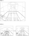
- the image processor 160 generates a composite front image by compositing a portion of the first front image into the second front image. That is, as illustrated in FIG. 4 , the image processor 160 sets the second front image taken by the lower camera 140 to the background, and composites the second front image and a portion of the first front image taken by the upper camera 120 at the same point of time as the second front image, in order to generate the composite front image. At this time, the front view secured in the composite front image is partially limited by the front wheels of the wheel loader 10, but may be enough to represent the front blind zone. Since the wheels may be included in the second front image, the image processor 160 may composite the first and second front images such that the region including the wheels is transparently represented through the first front image.
- the image processor 160 generates a composite front image by compositing a portion of the second front image into the first front image. That is, as illustrated in FIG. 5 , the image processor 160 sets the first front image taken by the upper camera 120 to the background, and composites the first front image and a portion of the second front image taken by the lower camera 140 at the same point of time as the first front image, in order to generate the composite front image. At this time, since the composite front image includes the first front image set to the background thereof, the composite front image has a wider view angle than the composite front image including the second front image set to the background thereof.
- the image processor 160 composites the first and second front images by applying different weights to the first and second front images according to the position of the bucket 12, when generating the composite front image.
- the image processor 160 applies a higher weight to the first front image when the bucket 12 is located at the bottom, and applies a higher weight to the second front image when the bucket 12 is located at the top.
- the image processor 160 may composite the second front image into the first front image such that a common area is represented with different color and brightness from the other area. For example, referring to FIG. 6 , the image processor 160 may composite the second front image into the first front image such that the common area is represented more brightly than the other area. That is, the image processor 160 generates the composite front image in which the common area of the first front image, with which the second front image is composited, is represented more brightly than the other area. In other words, the image processor 160 generates the composite front image in which the area where the first and second front images are composited is brightly represented, and the area of the first front image, with which the second front image is not composited, is darkly represented.
- the image processor 160 may adjust the color and transparency of the composite front image such that the color and transparency of the common area are not different from those of the other area, in order to minimize a sense of difference in the composite front image.
- the image processor 160 may generates the composite front image that represents the bucket 12 in an opaque state until the bucket 12 blocks the target, and represents the bucket 12 in a translucent or transparent state from the point of time that the bucket 12 blocks the target.
- the image processor 160 sets the transparencies of the first and second front images to 0.5, and then composites the first and second front images, in order to generate the composite front image.
- the image processor 160 dynamically adjusts the transparencies of the first and second front images according to the position of the bucket 12 or the arm connected to the bucket 12, and then composite the first and second front images, in order to generate the composite front image.
- the image processor 160 sets the weight of the first front image to a higher weight than the weight of the second front image. That is, when the bucket 12 is located at the bottom, the second front image has many blind zones. Thus, the image processor 160 sets the weight of the first front image having relatively few blind zones to a higher weight.
- the image processor 160 applies a higher weight to the first front image taken by the upper camera 120, in order to set the transparency of the first front image to a lower transparency than the second front image, and applies a lower weight to the second front image taken by the lower camera 140, in order to set the transparency of the second front image to a higher transparency than the first front image.
- the image processor 160 sets the weight of the second front image to a higher weight than the weight of the first front image. That is, when the bucket 12 is located at the top, the first front image has many blind zones. Thus, the image processor 160 sets the weight of the second front image having relatively few blind zones a higher weight. The image processor 160 applies a higher weight to the second front image taken by the lower camera 140, in order to set the transparency of the second front image to a lower transparency than the first front image, and applies a lower weight to the first front image taken by the upper camera 120, in order to set the transparency of the first front image to a higher transparency than the second front image.
- the image processor 160 may generate a composite front image by compositing the first front image and the second front image one-to-one. That is, the image processor 160 converts the first and second front images into plane or curved images on a screen (i.e. projection plane) at a predetermined distance, and then composites the plane or curved images, in order to generate the composite front image.
- a screen i.e. projection plane
- the image processor 160 may match the first and second front images by extending or reducing the two images without using the projection plane, and then composite the matched front images, in order to generate the composite front image.
- the image processor 160 requires distance information in order to composite the first and second front images one-to-one. That is, the image processor 160 converts the first and second front images into plane images by using the distances to the projection plane from where the first and second front images are taken, and composites the plane images, in order to generate the composite front image.
- the image processor 160 may acquire the distance information from the first and second front images. That is, the image processor 160 sets a plurality of random distances from the cameras to the projection plane. The image processor 160 converts the first front image into a first projection image on the basis of each of the random distances. The image processor 160 converts the second front image into a second projection image on the basis of each of the random distances. The image processor 160 calculates a coincidence (similarity) by comparing the first and second projection images which are acquired on the basis of the same random distance. The image processor 160 compares the coincidences acquired at the plurality of random distances, and sets the random distance, at which the highest coincidence is acquired, to distance information for composition.
- the image processor 160 sets the distance information when the wheel loader 10 is stopped.
- the image processor 160 generates the first and second projection images at each of the random distances.
- the image processor 160 sets the random distance, at which the coincidence between the first and second projection images is highest, to the distance information.
- the image processor 160 sets the distance information when the wheel loader 10 is stopped.
- the present disclosure is not limited thereto, but the image processor 160 may set the distance information even while the wheel loader 10 is operating.
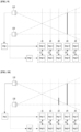
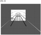
- FIG. 9 is based on the assumption that the image processor 160 sets first to fifth random distances d1 to d5, and a target is located at the fourth random distance d4.
- the image processor 160 generates a first-first projection image img1-1 and a second-first projection image img2-1 by converting a first front image img1 and a second front image img2 on the basis of the first random distance d1.
- the image processor 160 calculates a coincidence C1 between the first-first projection image img1-1 and the second-first projection image img2-1.
- the image processor 160 generates a first-second projection image img1-2 and a second-second projection image img2-2 by converting the first front image img1 and the second front image img2 on the basis of the second random distance d2.
- the image processor 160 calculates a coincidence C2 between the first-second projection image img1-2 and the second-second projection image img2-2.
- the image processor 160 generates a first-third projection image img1-3 and a second-third projection image img2-3 by converting the first front image img1 and the second front image img2 on the basis of the third random distance d3.
- the image processor 160 calculates a coincidence C3 between the first-third projection image img1-3 and the second-third projection image img2-3.
- the image processor 160 generates a first-fourth projection image img1-4 and a second-fourth projection image img2-4 by converting the first front image img1 and the second front image img2 on the basis of the fourth random distance d4.
- the image processor 160 calculates a coincidence C4 between the first-fourth projection image img1-4 and the second-fourth projection image img2-4.
- the image processor 160 generates a first-fifth projection image img1-5 and a second-fifth projection image img2-5 by converting the first front image img1 and the second front image img2 on the basis of the fifth random distance d5.
- the image processor 160 calculates a coincidence C5 between the first-fifth projection image img1-5 and the second-fifth projection image img2-5.
- the image processor 160 converts the first and second front images at a subsequent point of time into projection images by using preset distance information.
- the image processor 160 may reset the distance information when the position of the wheel loader 10 is changed, and set distance information for each point of time in order to raise the accuracy.
- the image processor 160 may convert the first and second front images by using the distance information manually set by a user, and then composite the converted images, in order to generate a composite front image.
- the image processor 160 may acquire the distance information through alignment between the upper camera 120 and the lower camera 140. That is, the image processor 160 may acquire the distance information through triangulation using the position information of the upper and lower cameras 120 and 140.
- the image processor 160 may acquire the distance information through a lidar, a 3D laser scanner, a TOF (Time-Of-Flight) depth camera, or an ultrasonic camera.
- the image processor 160 may set distance information for each area of an image by using a plurality of random distances.
- the image processor 160 converts the first and second front images into projection images on the basis of different pieces of distance information, which are set for an upper image area and a lower image area, and generates a composite front image by compositing the projection images.
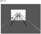
- FIG. 10 is based on the assumption that a first target is located at the fourth random distance d4, and a second target is located at the third random distance d3.
- the image processor 160 converts a first front image img1 and a second front image img2 into projection images img1-1 to img1-5 and img2-1 to img2-5 on the basis of the respective random distances.
- the image processor 160 sets the third random distance d3 to the distance information in the case of the lower image area onto which the second target is projected, and sets the fourth random distance d4 to the distance information in the case of the other image area except the lower image area.
- the image processor 160 generates a first projection image by converting a lower image area of the first front image on the basis of the third random distance d3, and converting the other image area of the first front image on the basis of the fourth random distance d4.
- the image processor 160 generates a second projection image by converting a lower image area of the second front image on the basis of the third random distance d3, and converting the other image area of the second front image on the basis of the fourth random distance d4.
- the image processor 160 generates a composite front image by compositing the first and second projection images acquired through the two pieces of distance information.
- the image processor 160 converts the first front image and the second front image into the first projection image and the second projection image by using the distance information.
- the image processor 160 sets feature points in the first and second front images, and sets distance information by using the feature points matched with both of the first and second front images.
- the image processor 160 detects an area which is to be used for composition, by using the feature points set in the first and second front images.
- the image processor 160 generates the first projection image by converting the area detected from the first front image on the basis of the distance information, and generates the second projection image by converting the area detected from the second front image on the basis of the distance information.
- the image processor 160 generates a composite projection image by compositing the first projection image and the second projection image.
- the image processor 160 sets the transparencies of the overlapping areas of the first and second projection images when generating the composite projection image, and generates a composite front image in which the bucket 12 is represented in a translucent state.
- the image processor 160 may generate a composite front image in which the overlapping areas of the first and second projection images are processed more brightly than non-overlapping areas.
Landscapes
- Engineering & Computer Science (AREA)
- Multimedia (AREA)
- Signal Processing (AREA)
- Mining & Mineral Resources (AREA)
- Civil Engineering (AREA)
- General Engineering & Computer Science (AREA)
- Structural Engineering (AREA)
- Image Processing (AREA)
- Closed-Circuit Television Systems (AREA)
- Component Parts Of Construction Machinery (AREA)
- Processing Or Creating Images (AREA)
Claims (14)
- Eine Frontbilderzeugungsvorrichtung für Schwermaschinen, die dazu konfiguriert ist, unter Verwendung von zwei oder mehr Kameras ein zusammengesetztes Frontbild zu erzeugen, wobei die Frontbilderzeugungsvorrichtung folgende Merkmale aufweist:eine obere Kamera (120), die auf einem Radlader (10) angeordnet ist und dazu konfiguriert ist, ein erstes Frontbild zu erzeugen;eine untere Kamera (140), die auf dem Radlader (10) angeordnet ist und dazu konfiguriert ist, ein zweites Frontbild zu erzeugen; undeine Bildverarbeitungseinrichtung (160), die dazu konfiguriert ist, durch Zusammensetzen des ersten Frontbilds und des zweiten Frontbilds ein zusammengesetztes Frontbild zu erzeugen,wobei die Bildverarbeitungseinrichtung (160) dazu konfiguriert ist, in Abhängigkeit von der Position eines Löffels (12) des Radladers (10) verschiedene Gewichtungen für das erste Frontbild und das zweite Frontbild festzulegen,dadurch gekennzeichnet, dassdie Bildverarbeitungseinrichtung (160) dazu konfiguriert ist, die Gewichtung des ersten Frontbilds auf eine höhere Gewichtung als die Gewichtung des zweiten Frontbilds festzulegen, wenn sich der Löffel (12) unten befindet, und die Bildverarbeitungseinrichtung (160) dazu konfiguriert ist, die Gewichtung des zweiten Frontbilds auf eine höhere Gewichtung als die Gewichtung des ersten Frontbilds festzulegen, wenn sich der Löffel oben befindet,wobei die Bildverarbeitungseinrichtung (160) dazu konfiguriert ist, unter dem ersten Frontbild und dem zweiten Frontbild für ein Frontbild mit einer vergleichsweise hohen Gewichtung eine vergleichsweise niedrigere Transparenz festzulegen.
- Die Frontbilderzeugungsvorrichtung gemäß Anspruch 1, wobei die Bildverarbeitungseinrichtung (160) dazu konfiguriert ist, durch Einfügen des gesamten oder von Teilen des zweiten Frontbilds in das erste Frontbild oder durch Einfügen des gesamten oder von Teilen des ersten Frontbilds in das zweite Frontbild ein zusammengesetztes Frontbild zu erzeugen.
- Die Frontbilderzeugungsvorrichtung gemäß Anspruch 1, wobei die Bildverarbeitungseinrichtung (160) dazu konfiguriert ist, ein zusammengesetztes Frontbild zu erzeugen, in dem zumindest der Löffel (12) und ein Arm des Radladers in einem durchscheinenden Zustand dargestellt ist.
- Die Frontbilderzeugungsvorrichtung gemäß Anspruch 1, wobei die Bildverarbeitungseinrichtung (160) dazu konfiguriert ist, das zusammengesetzte Frontbild zu erzeugen, das einen Löffel (12) des Radladers in einem nicht durchscheinenden Zustand darstellt, bis der Löffel (12) ein Ziel blockiert, und das den Löffel (12) ab einem Zeitpunkt, ab dem der Löffel (12) das Ziel blockiert, in einem durchscheinenden Zustand darstellt.
- Die Frontbilderzeugungsvorrichtung gemäß Anspruch 1, wobei die Bildverarbeitungseinrichtung ein erstes Projektionsbild und ein zweites Projektionsbild aneinander anpasst und dieselben zusammensetzt.
- Die Frontbilderzeugungsvorrichtung gemäß Anspruch 1, wobei die Bildverarbeitungseinrichtung (160) dazu konfiguriert ist, das erste Frontbild und das zweite Frontbild anhand von Abstandsinformationen in ein erstes Projektionsbild beziehungsweise ein zweites Projektionsbild umzuwandeln und durch Zusammensetzen des ersten und des zweiten Projektionsbilds ein zusammengesetztes Frontbild zu erzeugen.
- Die Frontbilderzeugungsvorrichtung gemäß Anspruch 6, wobei die Bildverarbeitungseinrichtung (160) dazu konfiguriert ist, eine Mehrzahl von zufälligen Abständen festzulegen, das erste Frontbild und das zweite Frontbild anhand der jeweiligen zufälligen Abstände in erste Projektionsbilder und zweite Projektionsbilder umzuwandeln, die Koinzidenzen zwischen den ersten Projektionsbildern und den zweiten Projektionsbildern bei den jeweiligen Zufallsabständen zu berechnen und den zufälligen Abstand, bei dem die höchste Koinzidenz erkannt wird, auf Abstandsinformationen festzulegen.
- Die Frontbilderzeugungsvorrichtung gemäß Anspruch 7, wobei die Bildverarbeitungseinrichtung (160) dazu konfiguriert ist, das erste Frontbild in eine Mehrzahl von Bereichen aufzuteilen und ein erstes Projektionsbild zu erzeugen, indem die Mehrzahl von Bereichen anhand von unterschiedlichen Abstandsinformationen für die jeweiligen Bereiche in ein Projektionsbild umgewandelt wird, und
das zweite Frontbild in eine Mehrzahl von Bereichen aufzuteilen und ein zweites Projektionsbild zu erzeugen, indem die Mehrzahl von Bereichen anhand von unterschiedlichen Abstandsinformationen für die jeweiligen Bereiche in ein Projektionsbild umgewandelt wird. - Die Frontbilderzeugungsvorrichtung gemäß Anspruch 1, wobei die Bildverarbeitungseinrichtung (160) dazu konfiguriert ist, Abstandsinformationen anhand von Merkmalspunkten festzulegen, die in dem ersten und dem zweiten Frontbild festgelegt sind.
- Die Frontbilderzeugungsvorrichtung gemäß Anspruch 9, wobei die Bildverarbeitungseinrichtung (160) dazu konfiguriert ist, anhand von Merkmalspunkten, die in dem ersten und dem zweiten Frontbild festgelegt sind, aus dem ersten und dem zweiten Frontbild einen Bereich zu erkennen, der zum Zusammensetzen zu verwenden ist.
- Die Frontbilderzeugungsvorrichtung gemäß Anspruch 6, wobei die Bildverarbeitungseinrichtung (160) dazu konfiguriert ist, eine Projektionsebene oder einen Projektionsraum festzulegen, um das erste und das zweite Frontbild in das erste und das zweite Projektionsbild umzuwandeln.
- Die Frontbilderzeugungsvorrichtung gemäß Anspruch 11, wobei die Bildverarbeitungseinrichtung (160) dazu konfiguriert ist, unter Verwendung von Informationen, die von einem Sensor oder einer Steuerungseinrichtung erhalten werden, Abstandsinformationen und Stellungsinformationen zu identifizieren und die Projektionsebene oder den Projektionsraum festzulegen.
- Die Frontbilderzeugungsvorrichtung gemäß Anspruch 11, wobei die Bildverarbeitungseinrichtung (160) dazu konfiguriert ist, durch Analysieren von Merkmalspunktinformationen und/oder Gekrümmte-Ebene-Informationen eines aufgenommenen Bilds eine Projektionsebene festzulegen.
- Die Frontbilderzeugungsvorrichtung gemäß Anspruch 1, wobei die Bildverarbeitungseinrichtung (160) dazu konfiguriert ist, durch Erweitern oder Reduzieren von Abschnitten der jeweiligen Bilder anhand von Merkmalspunkten der jeweiligen Bilder eine Mehrzahl von Bildern zusammenzusetzen.
Applications Claiming Priority (3)
| Application Number | Priority Date | Filing Date | Title |
|---|---|---|---|
| KR20190116070 | 2019-09-20 | ||
| KR1020190158373A KR102235123B1 (ko) | 2019-09-20 | 2019-12-02 | 중장비용 전방 영상 생성 장치 |
| PCT/KR2020/012605 WO2021054756A1 (ko) | 2019-09-20 | 2020-09-18 | 중장비용 전방 영상 생성 장치 |
Publications (3)
| Publication Number | Publication Date |
|---|---|
| EP4033749A1 EP4033749A1 (de) | 2022-07-27 |
| EP4033749A4 EP4033749A4 (de) | 2023-10-04 |
| EP4033749B1 true EP4033749B1 (de) | 2025-05-21 |
Family
ID=74882987
Family Applications (1)
| Application Number | Title | Priority Date | Filing Date |
|---|---|---|---|
| EP20865024.2A Active EP4033749B1 (de) | 2019-09-20 | 2020-09-18 | Frontbilderzeugungsvorrichtung für schwermaschinen |
Country Status (4)
| Country | Link |
|---|---|
| US (1) | US12035048B2 (de) |
| EP (1) | EP4033749B1 (de) |
| CN (1) | CN114375568B (de) |
| WO (1) | WO2021054756A1 (de) |
Families Citing this family (5)
| Publication number | Priority date | Publication date | Assignee | Title |
|---|---|---|---|---|
| KR20220107537A (ko) * | 2021-01-25 | 2022-08-02 | 주식회사 와이즈오토모티브 | 중장비용 전방 영상 생성 장치 |
| KR20230009172A (ko) * | 2021-07-08 | 2023-01-17 | 현대두산인프라코어(주) | 건설기계의 제어 시스템 및 방법 |
| US12227921B2 (en) | 2021-07-28 | 2025-02-18 | Hd Hyundai Infracore Co., Ltd. | System and method of controlling construction machinery |
| GB202305023D0 (en) * | 2023-04-04 | 2023-05-17 | Agco Int Gmbh | Camera system and method for generating a combined image projection |
| US20240424896A1 (en) * | 2023-06-23 | 2024-12-26 | Deere & Company | Work vehicle having speed and/or distance based decision support and intervention zones |
Family Cites Families (21)
| Publication number | Priority date | Publication date | Assignee | Title |
|---|---|---|---|---|
| US6411742B1 (en) | 2000-05-16 | 2002-06-25 | Adobe Systems Incorporated | Merging images to form a panoramic image |
| KR101640602B1 (ko) | 2009-12-15 | 2016-07-18 | 두산인프라코어 주식회사 | 건설기계의 사각지대 표시 장치 및 그 방법 |
| WO2012075250A1 (en) * | 2010-12-01 | 2012-06-07 | Magna Electronics Inc. | System and method of establishing a multi-camera image using pixel remapping |
| JP5858650B2 (ja) * | 2011-06-08 | 2016-02-10 | 富士通テン株式会社 | 画像生成装置、画像表示システム、及び、画像生成方法 |
| US9137262B2 (en) * | 2011-10-11 | 2015-09-15 | Citrix Systems, Inc. | Providing secure mobile device access to enterprise resources using application tunnels |
| KR101859229B1 (ko) * | 2011-12-19 | 2018-05-17 | 두산인프라코어 주식회사 | 건설기계의 작업 가이드 정보 표시 장치 및 방법 |
| EP2955914B1 (de) * | 2013-02-08 | 2018-10-17 | Hitachi Construction Machinery Co., Ltd. | Umgebungsüberwachungsvorrichtung für eine schwenkarbeitsmaschine |
| JP6095592B2 (ja) * | 2014-02-17 | 2017-03-15 | 日立建機株式会社 | 油圧ショベルの監視画像表示装置 |
| EP3135827B1 (de) * | 2014-04-25 | 2020-12-02 | Sumitomo (S.H.I.) Construction Machinery Co., Ltd. | Baumaschine |
| KR101611427B1 (ko) | 2014-12-26 | 2016-04-12 | 전자부품연구원 | 영상 처리 방법 및 이를 수행하는 영상 처리 장치 |
| KR102426631B1 (ko) | 2015-03-16 | 2022-07-28 | 현대두산인프라코어 주식회사 | 건설 기계의 사각 영역 표시 방법 및 이를 수행하기 위한 장치 |
| WO2016157463A1 (ja) | 2015-03-31 | 2016-10-06 | 株式会社小松製作所 | 作業機械の周辺監視装置 |
| US20160301864A1 (en) * | 2015-04-10 | 2016-10-13 | Caterpillar Inc. | Imaging processing system for generating a surround-view image |
| US9871968B2 (en) * | 2015-05-22 | 2018-01-16 | Caterpillar Inc. | Imaging system for generating a surround-view image |
| EP3985184B1 (de) | 2015-08-24 | 2025-10-29 | Komatsu Ltd. | Steuersystem für radlader und steuerungsverfahren dafür |
| JP2017198742A (ja) * | 2016-04-25 | 2017-11-02 | キヤノン株式会社 | 投影装置及びその制御方法、投影システム |
| CN107404643B (zh) * | 2016-05-18 | 2019-01-29 | 上海宽翼通信科技有限公司 | 一种三维摄像系统及其摄像方法 |
| KR101766711B1 (ko) | 2016-06-13 | 2017-08-10 | 전자부품연구원 | 다중 카메라를 이용한 가림 물체 투명 표시 장치, 방법 및 시스템 |
| KR102328031B1 (ko) * | 2016-12-08 | 2021-11-17 | 현대모비스 주식회사 | 탑-뷰 영상 생성 장치 및 그 방법 |
| KR20180078970A (ko) * | 2016-12-30 | 2018-07-10 | 화남전자 주식회사 | 건설장비의 주변부 모니터링을 위한 카메라 배치 구조 |
| JP6251453B1 (ja) * | 2017-02-09 | 2017-12-20 | 株式会社小松製作所 | 作業車両の周辺監視システム、作業車両、及び作業車両の周辺監視方法 |
-
2020
- 2020-09-18 EP EP20865024.2A patent/EP4033749B1/de active Active
- 2020-09-18 WO PCT/KR2020/012605 patent/WO2021054756A1/ko not_active Ceased
- 2020-09-18 CN CN202080064506.2A patent/CN114375568B/zh active Active
- 2020-09-18 US US17/761,985 patent/US12035048B2/en active Active
Also Published As
| Publication number | Publication date |
|---|---|
| US20220329731A1 (en) | 2022-10-13 |
| US12035048B2 (en) | 2024-07-09 |
| EP4033749A1 (de) | 2022-07-27 |
| CN114375568B (zh) | 2024-08-16 |
| CN114375568A (zh) | 2022-04-19 |
| EP4033749A4 (de) | 2023-10-04 |
| WO2021054756A1 (ko) | 2021-03-25 |
Similar Documents
| Publication | Publication Date | Title |
|---|---|---|
| EP4033749B1 (de) | Frontbilderzeugungsvorrichtung für schwermaschinen | |
| US12462601B2 (en) | Information processing device and recognition support method | |
| EP2978213A1 (de) | Peripherieüberwachungsvorrichtung für eine arbeitsmaschine | |
| US10527413B2 (en) | Outside recognition device | |
| EP2833162A1 (de) | Perimeterüberwachungsvorrichtung für eine arbeitsmaschine | |
| US20220166924A1 (en) | Image display apparatus | |
| KR102235123B1 (ko) | 중장비용 전방 영상 생성 장치 | |
| JP2013124467A (ja) | 建設機械の周囲画像表示装置及び周囲画像表示方法 | |
| WO2014073322A1 (ja) | 物体検出装置及び物体検出方法 | |
| JPH11222882A (ja) | 危険領域監視装置 | |
| EP3301913A1 (de) | Fotografievorrichtung und verfahren zur erfassung von tiefeninformationen | |
| JP2019067150A (ja) | 周辺監視装置および周辺監視方法 | |
| JP6088944B2 (ja) | 作業機械の周囲監視装置 | |
| KR101721655B1 (ko) | 객체 검출 시스템 및 방법 | |
| CN108699816A (zh) | 显示系统 | |
| JP3272696B2 (ja) | フェールセーフ機能を有する車外監視装置 | |
| KR20160110642A (ko) | 건설장비의 작업 현황 모니터링 장치 및 그 방법 | |
| US20240073393A1 (en) | Dynamic visual overlay for enhanced terrain perception on remote control construction equipment | |
| JP6988860B2 (ja) | 情報処理システム、情報処理方法及び情報処理プログラム | |
| KR20140118115A (ko) | 차량 주위 영상 보정 시스템 및 차량 주위 영상 보정 방법 | |
| KR20230082387A (ko) | 차량 영상 처리 장치 및 그 방법 | |
| US20240404002A1 (en) | Surroundings monitoring system | |
| WO2019070368A1 (en) | SYSTEM AND METHOD FOR DETECTING OBJECTS | |
| KR102836302B1 (ko) | 인프라 센서 설치 방법 | |
| JP2021193634A (ja) | 情報処理システム、情報処理方法及び情報処理プログラム |
Legal Events
| Date | Code | Title | Description |
|---|---|---|---|
| STAA | Information on the status of an ep patent application or granted ep patent |
Free format text: STATUS: THE INTERNATIONAL PUBLICATION HAS BEEN MADE |
|
| PUAI | Public reference made under article 153(3) epc to a published international application that has entered the european phase |
Free format text: ORIGINAL CODE: 0009012 |
|
| STAA | Information on the status of an ep patent application or granted ep patent |
Free format text: STATUS: REQUEST FOR EXAMINATION WAS MADE |
|
| 17P | Request for examination filed |
Effective date: 20220307 |
|
| AK | Designated contracting states |
Kind code of ref document: A1 Designated state(s): AL AT BE BG CH CY CZ DE DK EE ES FI FR GB GR HR HU IE IS IT LI LT LU LV MC MK MT NL NO PL PT RO RS SE SI SK SM TR |
|
| DAV | Request for validation of the european patent (deleted) | ||
| DAX | Request for extension of the european patent (deleted) | ||
| REG | Reference to a national code |
Ref country code: DE Ref legal event code: R079 Free format text: PREVIOUS MAIN CLASS: H04N0005232000 Ipc: E02F0009260000 Ref document number: 602020051804 Country of ref document: DE |
|
| A4 | Supplementary search report drawn up and despatched |
Effective date: 20230831 |
|
| RIC1 | Information provided on ipc code assigned before grant |
Ipc: H04N 23/90 20230101ALI20230825BHEP Ipc: H04N 23/50 20230101ALI20230825BHEP Ipc: H04N 5/262 20060101ALI20230825BHEP Ipc: E02F 9/26 20060101AFI20230825BHEP |
|
| GRAP | Despatch of communication of intention to grant a patent |
Free format text: ORIGINAL CODE: EPIDOSNIGR1 |
|
| STAA | Information on the status of an ep patent application or granted ep patent |
Free format text: STATUS: GRANT OF PATENT IS INTENDED |
|
| INTG | Intention to grant announced |
Effective date: 20241217 |
|
| RIC1 | Information provided on ipc code assigned before grant |
Ipc: H04N 23/90 20230101ALI20241206BHEP Ipc: H04N 23/50 20230101ALI20241206BHEP Ipc: H04N 5/262 20060101ALI20241206BHEP Ipc: E02F 9/26 20060101AFI20241206BHEP |
|
| GRAS | Grant fee paid |
Free format text: ORIGINAL CODE: EPIDOSNIGR3 |
|
| GRAA | (expected) grant |
Free format text: ORIGINAL CODE: 0009210 |
|
| STAA | Information on the status of an ep patent application or granted ep patent |
Free format text: STATUS: THE PATENT HAS BEEN GRANTED |
|
| P01 | Opt-out of the competence of the unified patent court (upc) registered |
Free format text: CASE NUMBER: APP_16602/2025 Effective date: 20250404 |
|
| AK | Designated contracting states |
Kind code of ref document: B1 Designated state(s): AL AT BE BG CH CY CZ DE DK EE ES FI FR GB GR HR HU IE IS IT LI LT LU LV MC MK MT NL NO PL PT RO RS SE SI SK SM TR |
|
| REG | Reference to a national code |
Ref country code: GB Ref legal event code: FG4D |
|
| REG | Reference to a national code |
Ref country code: CH Ref legal event code: EP |
|
| REG | Reference to a national code |
Ref country code: DE Ref legal event code: R096 Ref document number: 602020051804 Country of ref document: DE |
|
| REG | Reference to a national code |
Ref country code: IE Ref legal event code: FG4D |
|
| REG | Reference to a national code |
Ref country code: NL Ref legal event code: MP Effective date: 20250521 |
|
| PG25 | Lapsed in a contracting state [announced via postgrant information from national office to epo] |
Ref country code: PT Free format text: LAPSE BECAUSE OF FAILURE TO SUBMIT A TRANSLATION OF THE DESCRIPTION OR TO PAY THE FEE WITHIN THE PRESCRIBED TIME-LIMIT Effective date: 20250922 Ref country code: FI Free format text: LAPSE BECAUSE OF FAILURE TO SUBMIT A TRANSLATION OF THE DESCRIPTION OR TO PAY THE FEE WITHIN THE PRESCRIBED TIME-LIMIT Effective date: 20250521 Ref country code: ES Free format text: LAPSE BECAUSE OF FAILURE TO SUBMIT A TRANSLATION OF THE DESCRIPTION OR TO PAY THE FEE WITHIN THE PRESCRIBED TIME-LIMIT Effective date: 20250521 |
|
| REG | Reference to a national code |
Ref country code: LT Ref legal event code: MG9D |
|
| PG25 | Lapsed in a contracting state [announced via postgrant information from national office to epo] |
Ref country code: NO Free format text: LAPSE BECAUSE OF FAILURE TO SUBMIT A TRANSLATION OF THE DESCRIPTION OR TO PAY THE FEE WITHIN THE PRESCRIBED TIME-LIMIT Effective date: 20250821 Ref country code: GR Free format text: LAPSE BECAUSE OF FAILURE TO SUBMIT A TRANSLATION OF THE DESCRIPTION OR TO PAY THE FEE WITHIN THE PRESCRIBED TIME-LIMIT Effective date: 20250822 |
|
| PG25 | Lapsed in a contracting state [announced via postgrant information from national office to epo] |
Ref country code: NL Free format text: LAPSE BECAUSE OF FAILURE TO SUBMIT A TRANSLATION OF THE DESCRIPTION OR TO PAY THE FEE WITHIN THE PRESCRIBED TIME-LIMIT Effective date: 20250521 Ref country code: PL Free format text: LAPSE BECAUSE OF FAILURE TO SUBMIT A TRANSLATION OF THE DESCRIPTION OR TO PAY THE FEE WITHIN THE PRESCRIBED TIME-LIMIT Effective date: 20250521 |
|
| PG25 | Lapsed in a contracting state [announced via postgrant information from national office to epo] |
Ref country code: BG Free format text: LAPSE BECAUSE OF FAILURE TO SUBMIT A TRANSLATION OF THE DESCRIPTION OR TO PAY THE FEE WITHIN THE PRESCRIBED TIME-LIMIT Effective date: 20250521 |
|
| PGFP | Annual fee paid to national office [announced via postgrant information from national office to epo] |
Ref country code: GB Payment date: 20250927 Year of fee payment: 6 |
|
| PG25 | Lapsed in a contracting state [announced via postgrant information from national office to epo] |
Ref country code: HR Free format text: LAPSE BECAUSE OF FAILURE TO SUBMIT A TRANSLATION OF THE DESCRIPTION OR TO PAY THE FEE WITHIN THE PRESCRIBED TIME-LIMIT Effective date: 20250521 |
|
| PGFP | Annual fee paid to national office [announced via postgrant information from national office to epo] |
Ref country code: FR Payment date: 20250926 Year of fee payment: 6 |
|
| PG25 | Lapsed in a contracting state [announced via postgrant information from national office to epo] |
Ref country code: RS Free format text: LAPSE BECAUSE OF FAILURE TO SUBMIT A TRANSLATION OF THE DESCRIPTION OR TO PAY THE FEE WITHIN THE PRESCRIBED TIME-LIMIT Effective date: 20250821 |
|
| PG25 | Lapsed in a contracting state [announced via postgrant information from national office to epo] |
Ref country code: IS Free format text: LAPSE BECAUSE OF FAILURE TO SUBMIT A TRANSLATION OF THE DESCRIPTION OR TO PAY THE FEE WITHIN THE PRESCRIBED TIME-LIMIT Effective date: 20250921 |
|
| PG25 | Lapsed in a contracting state [announced via postgrant information from national office to epo] |
Ref country code: LV Free format text: LAPSE BECAUSE OF FAILURE TO SUBMIT A TRANSLATION OF THE DESCRIPTION OR TO PAY THE FEE WITHIN THE PRESCRIBED TIME-LIMIT Effective date: 20250521 |
|
| REG | Reference to a national code |
Ref country code: AT Ref legal event code: MK05 Ref document number: 1796858 Country of ref document: AT Kind code of ref document: T Effective date: 20250521 |
|
| PGFP | Annual fee paid to national office [announced via postgrant information from national office to epo] |
Ref country code: DE Payment date: 20250929 Year of fee payment: 6 |
|
| PG25 | Lapsed in a contracting state [announced via postgrant information from national office to epo] |
Ref country code: AT Free format text: LAPSE BECAUSE OF FAILURE TO SUBMIT A TRANSLATION OF THE DESCRIPTION OR TO PAY THE FEE WITHIN THE PRESCRIBED TIME-LIMIT Effective date: 20250521 Ref country code: DK Free format text: LAPSE BECAUSE OF FAILURE TO SUBMIT A TRANSLATION OF THE DESCRIPTION OR TO PAY THE FEE WITHIN THE PRESCRIBED TIME-LIMIT Effective date: 20250521 Ref country code: SM Free format text: LAPSE BECAUSE OF FAILURE TO SUBMIT A TRANSLATION OF THE DESCRIPTION OR TO PAY THE FEE WITHIN THE PRESCRIBED TIME-LIMIT Effective date: 20250521 |
|
| PG25 | Lapsed in a contracting state [announced via postgrant information from national office to epo] |
Ref country code: CZ Free format text: LAPSE BECAUSE OF FAILURE TO SUBMIT A TRANSLATION OF THE DESCRIPTION OR TO PAY THE FEE WITHIN THE PRESCRIBED TIME-LIMIT Effective date: 20250521 |
|
| PG25 | Lapsed in a contracting state [announced via postgrant information from national office to epo] |
Ref country code: EE Free format text: LAPSE BECAUSE OF FAILURE TO SUBMIT A TRANSLATION OF THE DESCRIPTION OR TO PAY THE FEE WITHIN THE PRESCRIBED TIME-LIMIT Effective date: 20250521 |
|
| PG25 | Lapsed in a contracting state [announced via postgrant information from national office to epo] |
Ref country code: SK Free format text: LAPSE BECAUSE OF FAILURE TO SUBMIT A TRANSLATION OF THE DESCRIPTION OR TO PAY THE FEE WITHIN THE PRESCRIBED TIME-LIMIT Effective date: 20250521 |
|
| PG25 | Lapsed in a contracting state [announced via postgrant information from national office to epo] |
Ref country code: IT Free format text: LAPSE BECAUSE OF FAILURE TO SUBMIT A TRANSLATION OF THE DESCRIPTION OR TO PAY THE FEE WITHIN THE PRESCRIBED TIME-LIMIT Effective date: 20250521 |
|
| PG25 | Lapsed in a contracting state [announced via postgrant information from national office to epo] |
Ref country code: RO Free format text: LAPSE BECAUSE OF FAILURE TO SUBMIT A TRANSLATION OF THE DESCRIPTION OR TO PAY THE FEE WITHIN THE PRESCRIBED TIME-LIMIT Effective date: 20250521 |