EP4033508A1 - Schalter für fahrzeug sowie fahrzeug - Google Patents
Schalter für fahrzeug sowie fahrzeug Download PDFInfo
- Publication number
- EP4033508A1 EP4033508A1 EP22152469.7A EP22152469A EP4033508A1 EP 4033508 A1 EP4033508 A1 EP 4033508A1 EP 22152469 A EP22152469 A EP 22152469A EP 4033508 A1 EP4033508 A1 EP 4033508A1
- Authority
- EP
- European Patent Office
- Prior art keywords
- push rod
- limiting body
- rocking bar
- elastic member
- switch
- Prior art date
- Legal status (The legal status is an assumption and is not a legal conclusion. Google has not performed a legal analysis and makes no representation as to the accuracy of the status listed.)
- Granted
Links
Images


Classifications
-
- H—ELECTRICITY
- H01—ELECTRIC ELEMENTS
- H01H—ELECTRIC SWITCHES; RELAYS; SELECTORS; EMERGENCY PROTECTIVE DEVICES
- H01H23/00—Tumbler or rocker switches, i.e. switches characterised by being operated by rocking an operating member in the form of a rocker button
- H01H23/02—Details
- H01H23/12—Movable parts; Contacts mounted thereon
-
- H—ELECTRICITY
- H01—ELECTRIC ELEMENTS
- H01H—ELECTRIC SWITCHES; RELAYS; SELECTORS; EMERGENCY PROTECTIVE DEVICES
- H01H23/00—Tumbler or rocker switches, i.e. switches characterised by being operated by rocking an operating member in the form of a rocker button
- H01H23/02—Details
- H01H23/12—Movable parts; Contacts mounted thereon
- H01H23/16—Driving mechanisms
-
- H—ELECTRICITY
- H01—ELECTRIC ELEMENTS
- H01H—ELECTRIC SWITCHES; RELAYS; SELECTORS; EMERGENCY PROTECTIVE DEVICES
- H01H23/00—Tumbler or rocker switches, i.e. switches characterised by being operated by rocking an operating member in the form of a rocker button
- H01H23/02—Details
- H01H23/12—Movable parts; Contacts mounted thereon
- H01H23/14—Tumblers
- H01H23/146—Tumblers having a generally tubular or conical elongated shape, e.g. dolly
-
- H—ELECTRICITY
- H01—ELECTRIC ELEMENTS
- H01H—ELECTRIC SWITCHES; RELAYS; SELECTORS; EMERGENCY PROTECTIVE DEVICES
- H01H23/00—Tumbler or rocker switches, i.e. switches characterised by being operated by rocking an operating member in the form of a rocker button
- H01H23/02—Details
- H01H23/04—Cases; Covers
- H01H23/06—Dustproof, splashproof, drip-proof, waterproof, or flameproof casings
-
- H—ELECTRICITY
- H01—ELECTRIC ELEMENTS
- H01H—ELECTRIC SWITCHES; RELAYS; SELECTORS; EMERGENCY PROTECTIVE DEVICES
- H01H23/00—Tumbler or rocker switches, i.e. switches characterised by being operated by rocking an operating member in the form of a rocker button
- H01H23/02—Details
- H01H23/08—Bases; Stationary contacts mounted thereon
-
- H—ELECTRICITY
- H01—ELECTRIC ELEMENTS
- H01H—ELECTRIC SWITCHES; RELAYS; SELECTORS; EMERGENCY PROTECTIVE DEVICES
- H01H23/00—Tumbler or rocker switches, i.e. switches characterised by being operated by rocking an operating member in the form of a rocker button
- H01H23/28—Tumbler or rocker switches, i.e. switches characterised by being operated by rocking an operating member in the form of a rocker button with three operating positions
- H01H23/30—Tumbler or rocker switches, i.e. switches characterised by being operated by rocking an operating member in the form of a rocker button with three operating positions with stable centre positions and one or both end positions unstable
-
- H—ELECTRICITY
- H01—ELECTRIC ELEMENTS
- H01H—ELECTRIC SWITCHES; RELAYS; SELECTORS; EMERGENCY PROTECTIVE DEVICES
- H01H2215/00—Tactile feedback
- H01H2215/004—Collapsible dome or bubble
- H01H2215/006—Only mechanical function
-
- H—ELECTRICITY
- H01—ELECTRIC ELEMENTS
- H01H—ELECTRIC SWITCHES; RELAYS; SELECTORS; EMERGENCY PROTECTIVE DEVICES
- H01H2221/00—Actuators
- H01H2221/008—Actuators other then push button
- H01H2221/016—Lever; Rocker
-
- H—ELECTRICITY
- H01—ELECTRIC ELEMENTS
- H01H—ELECTRIC SWITCHES; RELAYS; SELECTORS; EMERGENCY PROTECTIVE DEVICES
- H01H2221/00—Actuators
- H01H2221/024—Transmission element
- H01H2221/026—Guiding or lubricating nylon
-
- H—ELECTRICITY
- H01—ELECTRIC ELEMENTS
- H01H—ELECTRIC SWITCHES; RELAYS; SELECTORS; EMERGENCY PROTECTIVE DEVICES
- H01H2221/00—Actuators
- H01H2221/024—Transmission element
- H01H2221/03—Stoppers for on or off position
-
- H—ELECTRICITY
- H01—ELECTRIC ELEMENTS
- H01H—ELECTRIC SWITCHES; RELAYS; SELECTORS; EMERGENCY PROTECTIVE DEVICES
- H01H2221/00—Actuators
- H01H2221/036—Return force
- H01H2221/044—Elastic part on actuator or casing
-
- H—ELECTRICITY
- H01—ELECTRIC ELEMENTS
- H01H—ELECTRIC SWITCHES; RELAYS; SELECTORS; EMERGENCY PROTECTIVE DEVICES
- H01H2227/00—Dimensions; Characteristics
- H01H2227/022—Collapsable dome
-
- H—ELECTRICITY
- H01—ELECTRIC ELEMENTS
- H01H—ELECTRIC SWITCHES; RELAYS; SELECTORS; EMERGENCY PROTECTIVE DEVICES
- H01H2229/00—Manufacturing
- H01H2229/064—Eliminating tolerances
-
- H—ELECTRICITY
- H01—ELECTRIC ELEMENTS
- H01H—ELECTRIC SWITCHES; RELAYS; SELECTORS; EMERGENCY PROTECTIVE DEVICES
- H01H2231/00—Applications
- H01H2231/026—Car
-
- H—ELECTRICITY
- H01—ELECTRIC ELEMENTS
- H01H—ELECTRIC SWITCHES; RELAYS; SELECTORS; EMERGENCY PROTECTIVE DEVICES
- H01H2237/00—Mechanism between key and laykey
- H01H2237/006—Guided plunger or ball
Definitions
- the invention relates to the technical field of switches, and particularly provides a switch for a vehicle and a vehicle.
- a novel switch for a vehicle and a vehicle are required in this field to solve the problems of switch zero drift and shaking caused by the existence of the dimensional deviation of the switch of the existing vehicle.
- the invention provides a first implementation of a switch for a vehicle.
- the switch comprises a pressing rocking bar, a first push rod, a second push rod, a first elastic member, a second elastic member, and a housing, wherein the pressing rocking bar is pivotally connected to the housing, and a position point at which the pressing rocking bar is pivotally connected to the housing is disposed between the first push rod and the second push rod;
- the switch further comprises a first limiting body and a second limiting body, the first limiting body and the second limiting body are fixedly arranged, the first push rod runs through the first limiting body and abuts against the bottom of a first end of the pressing rocking bar, the second push rod runs through the second limiting body and abuts against the bottom of a second end of the pressing rocking bar, and the second push rod abuts against the
- the first push rod is provided with a first protrusion
- the first protrusion is disposed between the first limiting body and the first elastic member
- the moving gap is reserved between the first protrusion and the first limiting body
- the second push rod is provided with a second protrusion
- the second push rod abuts against the second limiting body through the second protrusion.
- a height from the bottom of the first limiting body to the reference surface is less than a height from the bottom of the second limiting body to the reference surface, and a height difference is a height of the moving gap.
- the second protrusion is disposed between the second limiting body and the second elastic member; and with the bottom of the pressing rocking bar used as a reference surface, a height from the reference surface to a top end of the first protrusion is greater than a height from the reference surface to a top end of the second protrusion, and a height difference is a height of the moving gap.
- cross sections of the first limiting body and the second limiting body are each in an n shape, the first push rod is slidably connected to an inner wall of the first limiting body, and the second push rod is slidably connected to an inner wall of the second limiting body; and/or, the first limiting body and the second limiting body are integrally connected to the housing.
- a position point at which the pressing rocking bar is pivotally connected to the housing is located at a middle portion of the pressing rocking bar; and/or, the pressing rocking bar comprises a poking key and a rocking bar body, the poking key is disposed on the rocking bar body, the first push rod runs through the first limiting body and abuts against the bottom of a first end of the rocking bar body, and the second push rod runs through the second limiting body and abuts against the bottom of a second end of the rocking bar body.
- the invention further provides a second implementation of a switch for a vehicle.
- the switch comprises a pressing rocking bar, a first push rod, a second push rod, a first elastic member, a second elastic member, and a housing, wherein the pressing rocking bar is pivotally connected to the housing, and a position point at which the pressing rocking bar is pivotally connected to the housing is disposed between the first push rod and the second push rod;
- the switch further comprises a first limiting body and a second limiting body, the first limiting body and the second limiting body are fixedly arranged, the first push rod runs through the first limiting body and abuts against the bottom of a first end of the pressing rocking bar, the second push rod runs through the second limiting body and abuts against the bottom of a second end of the pressing rocking bar, and the second push rod abuts against the second limiting body; and the first elastic member is fixedly arranged and connected to the bottom of the first push rod, the second elastic member is fixedly arranged and connected to
- the invention further provides a third implementation of a switch for a vehicle.
- the switch comprises a pressing rocking bar, a first push rod, a second push rod, a first elastic member, a second elastic member, and a housing, wherein the pressing rocking bar is pivotally connected to the housing, and a position point at which the pressing rocking bar is pivotally connected to the housing is disposed between the first push rod and the second push rod;
- the switch further comprises a first limiting body and a second limiting body, the first limiting body and the second limiting body are fixedly arranged, the first push rod runs through the first limiting body and abuts against the bottom of a first end of the pressing rocking bar, and the second push rod runs through the second limiting body and abuts against the bottom of a second end of the pressing rocking bar; and the first elastic member is fixedly arranged and connected to the bottom of the first push rod, the first push rod abuts against the first limiting body and makes the first elastic member in a compressed state, the
- cross sections of the first limiting body and the second limiting body are each in an n shape
- the first push rod is slidably connected to an inner wall of the first limiting body
- the second push rod is slidably connected to an inner wall of the second limiting body
- the first push rod is provided with a first protrusion
- the second push rod is provided with a second protrusion
- the first protrusion abuts against the bottom of the first limiting body and makes the first elastic member in a compressed state
- the second protrusion abuts against the bottom of the second limiting body and makes the second elastic member in a compressed state.
- the invention further provides a vehicle.
- the vehicle comprises a switch for a vehicle according to any one of the foregoing technical solutions.
- the switch comprises a pressing rocking bar, a first push rod, a second push rod, a first elastic member, a second elastic member, and a housing, wherein the pressing rocking bar is pivotally connected to the housing, and a position point at which the pressing rocking bar is pivotally connected to the housing is disposed between the first push rod and the second push rod;
- the switch further comprises a first limiting body and a second limiting body, the first push rod runs through the first limiting body and abuts against the bottom of a first end of the pressing rocking bar, the second push rod runs through the second limiting body and abuts against the bottom of a second end of the pressing rocking bar, and the second push rod abuts against the second limiting body; and the first elastic member is fixedly arranged and connected to the bottom of the first push rod, the second elastic member is fixedly arranged and connected to the bottom of the second push rod, prepressures on the second elastic member and the first
- the first push rod and the second push rod can be always attached to the pressing rocking bar through dynamic compensation of the moving gap, thereby forming a very stable position and preventing the shaking of the switch.
- the number of tolerance dimension chains is further greatly reduced, and it is easier to control dimensions, thereby ensuring position accuracy of the switch.
- connection may be a fixed connection, a detachable connection or an integral connection; may be a mechanical connection or an electrical connection; and may be a direct connection, an indirect connection by means of an intermediary, or internal communication between two elements.
- a connection may be a fixed connection, a detachable connection or an integral connection; may be a mechanical connection or an electrical connection; and may be a direct connection, an indirect connection by means of an intermediary, or internal communication between two elements.
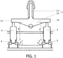
- a working principle of a switch in the prior art is that when an external force is applied to a first end 11 of a pressing rocking bar 1, the pressing rocking bar 1 presses a first push rod 2, so that the first push rod 2 triggers a trigger switch of the first end 11 to implement connection of a circuit, and when the external force is released, a first elastic member 4 resets the first push rod 2 to implement disconnection of the circuit; when an external force is applied to a second end 12 of the pressing rocking bar 1, the pressing rocking bar 1 presses a second push rod 3, so that the second push rod 3 triggers a trigger switch of the second end 12 to implement connection of a circuit, and when the external force is released, a second elastic member 5 resets the second push rod 3 to implement disconnection of the circuit.
- Factors that limit the position of the pressing rocking bar 1 include a height (H4) of the first elastic member 4 and a height (H2) of the second elastic member 5, a height (H3) from a top end of the first push rod 2 to a top end of the first elastic member 4, and a height (HI) from a top end of the second push rod 3 to a top end of the second elastic member 5.
- the tolerance dimension chains according to the invention are each an overall dimension or partial dimension of a member that affects the position of the pressing rocking bar 1, such as the height (H4) of the first elastic member 4 and the height (H3) from the top end of the first push rod 2 to the top end of the first elastic member 4.
- the invention provides three implementations of a switch for a vehicle, and technical solutions of the three implementations are as follows.
- the switch according to the invention is a toggle switch, and its working principle is as follows: when an external force is applied to a first end 11 of a pressing rocking bar 1, the pressing rocking bar 1 presses a first push rod 2, so that the first push rod 2 triggers a trigger switch of the first end 11 to implement connection of a circuit, and when the external force is released, a first elastic member 4 resets the first push rod 2 to implement disconnection of the circuit; when an external force is applied to a second end 12 of the pressing rocking bar 1, the pressing rocking bar 1 presses a second push rod 3, so that the second push rod 3 triggers a trigger switch of the second end 12 to implement connection of a circuit, and when the external force is released, a second elastic member 5 resets the second push rod 3 to implement disconnection of the circuit.
- a first limiting body 6 and a second limiting body 7 limit a movement stroke of the first push rod 2 and the second push rod 3, which can prevent the first push rod
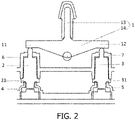
- the switch comprises a pressing rocking bar 1, a first push rod 2, a second push rod 3, a first elastic member 4, a second elastic member 5, and a housing, wherein the pressing rocking bar 1 is pivotally connected to the housing, and a position point at which the pressing rocking bar 1 is pivotally connected to the housing is disposed between the first push rod 2 and the second push rod 3;
- the switch further comprises a first limiting body 6 and a second limiting body 7, the first limiting body 6 and the second limiting body 7 are fixedly arranged, the first push rod 2 runs through the first limiting body 6 and abuts against the bottom of a first end 11 of the pressing rocking bar 1, and the second push rod 3 runs through the second limiting body 7 and abuts against the bottom of a second end 12 of the pressing rocking bar 1; and the first elastic member 4 is fixedly arranged and connected to the bottom of the first push rod 2, the first push rod 2 abuts against the first elastic member 4
- the first push rod 2 abuts against the first limiting body 6, and the first elastic member 4 is in a compressed state; and the second push rod 3 abuts against the second limiting body 7, and the second elastic member 5 is in a compressed state. That is, the first limiting body 6 and the second limiting body 7 restrict the movement of the first push rod 2 and the second push rod 3 toward the pressing rocking bar 1, so that the first push rod 2 always abuts against the first limiting body 6 and the second push rod 3 always abuts against the second limiting body 7. In this case, no matter how much elastic force the first elastic member 4 and the second elastic member 5 release, neither the first push rod 2 nor the second push rod 3 can be jacked up.
- the design mode in which the first push rod 2 and the second push rod 3 are always attached to the first limiting body 6 and the second limiting body 7 prevents tolerance chains of a switch system from being affected by heights of the first elastic member 4 and the second elastic member 5, so that the number of tolerance dimension chains can be reduced to two, thereby implementing better dimensional control, reducing zero drift, ensuring position accuracy of the switch, and preventing shaking of the switch.
- cross sections of the first limiting body 6 and the second limiting body 7 are each in an n shape
- the first push rod 2 is slidably connected to an inner wall of the first limiting body 6
- the second push rod 3 is slidably connected to an inner wall of the second limiting body 7
- the first push rod 2 is provided with a first protrusion 21
- the second push rod 3 is provided with a second protrusion 31
- the first protrusion 21 abuts against the bottom of the first limiting body 6 such that the first elastic member 4 is in a compressed state
- the second protrusion 31 abuts against the bottom of the second limiting body 7 such that the second elastic member 5 is in a compressed state.
- the design mode in which the cross sections of the first limiting body 6 and the second limiting body 7 are each in an n shape enables the first push rod 2 and the second push rod 3 to have a greater contact area with the first limiting body 6 and the second limiting body 7, thereby ensuring that the first push rod 2 and the second push rod 3 do not deviate relative to a pressing direction, preventing shaking of the first push rod 2 and the second push rod 3 in the first limiting body 6 and the second limiting body 7, and further ensuring stability of the switch.
- the number of tolerance chains of the switch system is independent of the heights of the first elastic member 4 and the second elastic member 5, and the number of the dimension chains is reduced, thereby implementing better dimensional control.
- the dimension design reduces zero drift, ensures position accuracy of the switch, and prevents shaking of the switch.
- the switch comprises a pressing rocking bar 1, a first push rod 2, a second push rod 3, a first elastic member 4, a second elastic member 5, and a housing, wherein the pressing rocking bar 1 is pivotally connected to the housing, and a position point at which the pressing rocking bar 1 is pivotally connected to the housing is disposed between the first push rod 2 and the second push rod 3;
- the switch further comprises a first limiting body 6 and a second limiting body 7, the first push rod 2 runs through the first limiting body 6 and abuts against the bottom of a first end 11 of the pressing rocking bar 1, the second push rod 3 runs through the second limiting body 7 and abuts against the bottom of a second end 12 of the pressing rocking bar 1, and the second push rod 3 abuts against the second limiting body 7; and the first elastic member 4 is fixedly arranged and connected to the bottom of the first push rod 2, and the second elastic member 5 is fixedly arranged and connected to the bottom
- first limiting body 6 and the second limiting body 7 may be integrally connected to the housing, which can simplify a production process, or may be connected to the housing in a split manner, which facilitates production and operation.
- the torque of the second push rod 3 acting on the second end 12 of the pressing rocking bar 1 is greater than the torque of the first push rod 2 acting on the first end 11 of the pressing rocking bar 1, in a situation in which no limitation is imposed, the second push rod 3 will jack up the pressing rocking bar 1, and the first push rod 2 will be pressed according to the lever principle, thereby turning on the trigger switch of the first end 11. Therefore, in the invention, the second push rod 3 abuts against the second limiting body 7, thereby limiting the movement of the second push rod 3 toward the pressing rocking bar 1, and preventing the trigger switch of the first end 11 from being triggered.
- the moving gap 8 is reserved between the first limiting body 6 and the first push rod 2 in the pressing direction of the first push rod 2, so that the first push rod 2 can be urged to move toward the pressing rocking bar 1 under the action of the elastic force of the first elastic member 4 to fill the moving gap 8. Furthermore, only through an accurate dimension design of the second push rod 3, the second push rod 3 is always attached to the pressing rocking bar 1, and the pressing rocking bar 1 is kept at a zero position.
- the arrangement of the moving gap 8 enables the first push rod 2 to move upward until the first push rod is attached to the first end 11 of the pressing rocking bar 1, thereby forming a very stable position, ensuring position accuracy of the switch, avoiding shaking of the switch, and improving the product texture. That is to say, the height of the moving gap 8 can compensate for a tolerance height between the first push rod 2 and the pressing rocking bar 1.
- the second push rod 3 acting on the second end 12 of the pressing rocking bar 1 is greater than the torque of the first push rod 2 acting on the first end 11 of the pressing rocking bar 1, the second push rod 3 cannot be pressed downward, thereby preventing the trigger switch from being triggered.
- This arrangement makes the second end 12 of the pressing rocking bar 1 form a very stable position, which becomes a positioning reference of the entire switch system, and reduces a double-side deviation of the pressing rocking bar 1 to a one-side deviation at the zero position. That is, the stable position of the pressing rocking bar 1 depends on the position of a final top end of the second push rod 3 (because of the existence of the asymmetric torque, the pressing rocking bar 1 is attached to the position of the top end of the second push rod 3 when the pressing rocking bar is in the final stable state). Therefore, the tolerance dimension chain of the switch system is mainly related to a machining error of a structural dimension on the side of the second push rod 3, and the tolerance dimension chain on the side of the first push rod 2 is reduced to zero.
- machining error on the side of the first push rod 2 does not cause the deviation of the entire structure.
- precise dimensional control only involves a length of A, that is, the height from a reference surface to the bottom of the second limiting body 7 with the bottom of the pressing rocking bar 1 as the reference surface, and precise dimension design is performed on the second push rod 3 of this part, while the height of the moving gap 8 is subjected to a relatively loose limitation and is greater than or equal to the tolerance that needs compensation. Therefore, a dimension of a member that determines the size of the moving gap is relatively loose in design, and may not be precisely controlled. Therefore, the dimension design may be ignored as zero, and the number of final dimension tolerance chains is reduced to one. Therefore, this arrangement can implement better dimensional control, reduce zero drift and ensure position accuracy of the switch.
- the first push rod 2 is provided with a first protrusion 21, the first protrusion 21 is disposed between the first limiting body 6 and the first elastic member 4, the moving gap 8 is reserved between the first protrusion 21 and the first limiting body 6, the second push rod 3 is provided with a second protrusion 31, and the second push rod 3 abuts against the second limiting body 7 through the second protrusion 31. That is, the elastic force of the first elastic member 4 forces the first protrusion 21 to move toward the pressing rocking bar 1, so as to fill the moving gap 8, make the first push rod 2 and the second push rod 3 always attached to the pressing rocking bar 1, ensure position accuracy and keep a stable state.
- the moving gap 8 between the first protrusion 21 and the first limiting body 6 is arranged by means of a plurality of implementations. In the invention, the following two implementations are used as examples for description.
- the first implementation is as follows: design dimensions of the first push rod 2 and the second push rod 3 are the same. With the bottom of the pressing rocking bar 1 used as a reference surface, a height from the bottom of the first limiting body 6 to the reference surface is less than a height from the bottom of the second limiting body 7 to the reference surface, and a height difference is a height of the moving gap 8.
- the height from the bottom of the first limiting body 6 to the reference surface is C in Fig. 3
- the height from the bottom of the second limiting body 7 to the reference surface is A in the figure
- the same push rod is used as the first push rod 2 and the second push rod 3, which greatly improves consistency of push rod components, improves dimensional stability of the system, and reduces a production cost.
- the second implementation is as follows: design dimensions of the first push rod 2 and the second push rod 3 are different, and thicknesses and positions of the first protrusion 21 and the second protrusion 31 are different.
- the second protrusion 31 is disposed between the second limiting body 7 and the second elastic member 5. With the bottom of the pressing rocking bar 1 used as a reference surface, a height from the reference surface to a top end of the first protrusion 21 is greater than a height from the reference surface to a top end of the second protrusion 31, and a height difference is a height of the moving gap 8.
- the height from the reference surface to the top end of the first protrusion 21 is B in Fig. 4
- the height from the reference surface to the top end of the second protrusion 31 is A in the figure
- cross sections of the first limiting body 6 and the second limiting body 7 are each in an n shape, the first push rod 2 is slidably connected to an inner wall of the first limiting body 6, and the second push rod 3 is slidably connected to an inner wall of the second limiting body 7.
- the design mode in which the cross sections of the first limiting body 6 and the second limiting body 7 are each in an n shape enables the first push rod 2 and the second push rod 3 to have a greater contact area with the first limiting body 6 and the second limiting body 7, and prevents the first push rod 2 and the second push rod 3 from shaking.
- the first push rod 2 as an example for description, it can be seen from a sectional view that, in the pressing direction, contact points between the first push rod 2 and the first limiting body 6 form a longer straight line, thereby ensuring that the first push rod 2 does not deviate relative to the pressing direction, preventing the first push rod 2 from shaking in the first limiting body 6, and further ensuring stability of the switch.
- a position point at which the pressing rocking bar 1 is pivotally connected to the housing is located at a middle portion of the pressing rocking bar 1.
- This arrangement can eliminate the influence of dead weight of the pressing rocking bar 1 on balance thereof.
- asymmetric torque can be designed more conveniently. That is, if distances from position points of the first push rod 2 and the second push rod 3 acting on two ends of the pressing rocking bar 1 to pivotally connected position points are the same, force arms are the same.
- different prepressures can be designed by using the first elastic member 4 and the second elastic member 5, to achieve an effect of different torques at two ends.
- the prepressure of the second elastic member 5 is 0.5 N higher than the prepressure of the first elastic member 4, so that a pressing touch is not affected while position accuracy of the switch is ensured.
- the pressing rocking bar 1 comprises a poking key 13 and a rocking bar body 14, the poking key 13 is disposed on the rocking bar body 14, the first push rod 2 runs through the first limiting body 6 and abuts against the bottom of a first end 11 of the rocking bar body 14, and the second push rod 3 runs through the second limiting body 7 and abuts against the bottom of a second end 12 of the rocking bar body 14. That is, the arrangement of the poking key 13 can facilitate user operation and improve user experience.
- an outer side of a toggle part is coated with a decorative skin, which makes the appearance of the switch more beautiful, and also plays the role of skid resistance and the like.
- the switch comprises a pressing rocking bar 1, a first push rod 2, a second push rod 3, a first elastic member 4, a second elastic member 5, and a housing, wherein the pressing rocking bar 1 is pivotally connected to the housing, and a position point at which the pressing rocking bar 1 is pivotally connected to the housing is disposed between the first push rod 2 and the second push rod 3;
- the switch further comprises a first limiting body 6 and a second limiting body 7, wherein the first limiting body 6 and the second limiting body 7 are fixedly arranged, the first push rod 2 runs through the first limiting body 6 and abuts against the bottom of a first end 11 of the pressing rocking bar 1, the second push rod 3 runs through the second limiting body 7 and abuts against the bottom of a second end 12 of the pressing rocking bar 1, and the second push rod 3 abuts against the second limiting body 7; and the first elastic
- the first push rod 2 is a cylindrical rod without a boss, the first limiting body 6 cannot limit the movement of the first push rod 2 in the pressing direction. Under the action of the first elastic member 4, the first push rod 2 can be pushed to always move toward the pressing rocking bar 1 until the first push rod is blocked by torque greater than torque of the first push rod 2 acting on the pressing rocking bar 1. Therefore, this arrangement can ensure that the first push rod 2 and the second push rod 3 are always attached to the pressing rocking bar 1, and the second push rod 3 cannot be pressed downward, so that the position accuracy and stability of the switch can be ensured only by a precise dimension design of the second push rod 3, and the switch can be prevented from shaking.
- the cylindrical rod is simple in structure and convenient to manufacture and can reduce a production cost.
- the first elastic member 4 and the second elastic member 5 according to the invention may be rubber pads, or springs, or the like, as long as they have elasticity and enable the first push rod 2 and the second push rod 3 to move toward the pressing rocking bar 1.
- the zero drift of the switch according to the invention is reduced to the largest extent through the design mode in which the first protrusion 21 and the second protrusion 31 are always attached to the first limiting body 6 and the second limiting body 7.
- a double-side deviation is reduced to a one-side deviation when the switch is at a zero position, and the number of dimension chains is reduced to a half of the original number, thereby ensuring a more accurate position and ensuring that the switch is always in a stable state.
- the first push rod 2 may be provided with an elastic clamping head
- the first limiting body 6 may be provided with a clamping groove suitable for the elastic clamping head
- a distance between the elastic clamping head and the clamping groove is the moving gap 8.
- the clamping groove can limit the first push rod 2.
- the elastic clamping head on the first push rod 2 can be separated from the clamping groove as long as the moving gap 8 is reserved between the first limiting body 6 and the first push rod 2.
- the first protrusion 21 may abut against an inner wall of a top side of the n-shaped first limiting body 6, as long as the first protrusion 21 abuts against the first limiting body 6.
- cross sections of the first limiting body 6 and the second limiting body 7 may be rectangular or in another shape, as long as the first push rod 2 and the second push rod 3 can be limited.
- a position point at which the pressing rocking bar 1 is pivotally connected to the housing may not be located on a middle portion of the pressing rocking bar 1, as long as the torque of the second push rod 3 acting on the second end 12 of the pressing rocking bar 1 is greater than the torque of the first push rod 2 acting on the first end 11 of the pressing rocking bar 1.
- the invention further provides a vehicle.
- the vehicle is provided with a switch for a vehicle according to any one of the foregoing implementations.
Landscapes
- Push-Button Switches (AREA)
Applications Claiming Priority (1)
| Application Number | Priority Date | Filing Date | Title |
|---|---|---|---|
| CN202110083700.1A CN112927972B (zh) | 2021-01-21 | 2021-01-21 | 用于车辆的开关及车辆 |
Publications (2)
| Publication Number | Publication Date |
|---|---|
| EP4033508A1 true EP4033508A1 (de) | 2022-07-27 |
| EP4033508B1 EP4033508B1 (de) | 2024-12-11 |
Family
ID=76164128
Family Applications (1)
| Application Number | Title | Priority Date | Filing Date |
|---|---|---|---|
| EP22152469.7A Active EP4033508B1 (de) | 2021-01-21 | 2022-01-20 | Schalter für fahrzeug sowie fahrzeug |
Country Status (3)
| Country | Link |
|---|---|
| US (1) | US11915892B2 (de) |
| EP (1) | EP4033508B1 (de) |
| CN (1) | CN112927972B (de) |
Families Citing this family (1)
| Publication number | Priority date | Publication date | Assignee | Title |
|---|---|---|---|---|
| CN113611561A (zh) * | 2021-07-31 | 2021-11-05 | 亮兮柯电气(嘉兴)有限公司 | 一种防水开关 |
Citations (4)
| Publication number | Priority date | Publication date | Assignee | Title |
|---|---|---|---|---|
| JPH0668269U (ja) * | 1993-03-10 | 1994-09-22 | 自動車電機工業株式会社 | スイッチ |
| JPH07161258A (ja) * | 1993-12-03 | 1995-06-23 | Yazaki Corp | パワーウインドスイッチ |
| JP2008135282A (ja) * | 2006-11-28 | 2008-06-12 | Calsonic Kansei Corp | シーソースイッチ |
| JP2015207411A (ja) * | 2014-04-18 | 2015-11-19 | パナソニック エコソリューションズ朝日株式会社 | スイッチ装置およびそれを用いた車両 |
Family Cites Families (10)
| Publication number | Priority date | Publication date | Assignee | Title |
|---|---|---|---|---|
| AU627396B2 (en) * | 1990-02-14 | 1992-08-20 | Yazaki Corporation | Two-stage rubber switch |
| JPH0757586A (ja) * | 1993-08-09 | 1995-03-03 | Sumitomo Wiring Syst Ltd | 押し釦スイッチのラバーコンタクト |
| US5584380A (en) * | 1993-09-02 | 1996-12-17 | Sumitomo Wiring Systems, Ltd. | Seesaw switch |
| JP3758129B2 (ja) * | 1999-10-15 | 2006-03-22 | 矢崎総業株式会社 | スイッチ装置 |
| JP2002175746A (ja) * | 2000-12-06 | 2002-06-21 | Yazaki Corp | 多段クリックスイッチ |
| JP2002208329A (ja) * | 2001-01-12 | 2002-07-26 | Yazaki Corp | 2段節度のスイッチ構造 |
| DE10117596C1 (de) * | 2001-04-07 | 2002-11-28 | Itt Mfg Enterprises Inc | Wipp- und/oder Tastschalter |
| JP2011198531A (ja) * | 2010-03-18 | 2011-10-06 | Kobakku:Kk | シーソーロッカーキー |
| CN210778362U (zh) * | 2019-10-30 | 2020-06-16 | 宁波公牛电器有限公司 | 一种复位开关 |
| CN211828588U (zh) * | 2019-11-26 | 2020-10-30 | 宁波公牛电器有限公司 | 一种具有防按钮间隙不均结构的开关 |
-
2021
- 2021-01-21 CN CN202110083700.1A patent/CN112927972B/zh active Active
-
2022
- 2022-01-20 EP EP22152469.7A patent/EP4033508B1/de active Active
- 2022-01-20 US US17/579,855 patent/US11915892B2/en active Active
Patent Citations (4)
| Publication number | Priority date | Publication date | Assignee | Title |
|---|---|---|---|---|
| JPH0668269U (ja) * | 1993-03-10 | 1994-09-22 | 自動車電機工業株式会社 | スイッチ |
| JPH07161258A (ja) * | 1993-12-03 | 1995-06-23 | Yazaki Corp | パワーウインドスイッチ |
| JP2008135282A (ja) * | 2006-11-28 | 2008-06-12 | Calsonic Kansei Corp | シーソースイッチ |
| JP2015207411A (ja) * | 2014-04-18 | 2015-11-19 | パナソニック エコソリューションズ朝日株式会社 | スイッチ装置およびそれを用いた車両 |
Also Published As
| Publication number | Publication date |
|---|---|
| US20220230823A1 (en) | 2022-07-21 |
| CN112927972A (zh) | 2021-06-08 |
| CN112927972B (zh) | 2025-09-30 |
| EP4033508B1 (de) | 2024-12-11 |
| US11915892B2 (en) | 2024-02-27 |
Similar Documents
| Publication | Publication Date | Title |
|---|---|---|
| EP4033508A1 (de) | Schalter für fahrzeug sowie fahrzeug | |
| JP6805405B2 (ja) | 割ナット開閉装置 | |
| US10786386B2 (en) | Medical body position retaining belt securing device | |
| TW201039938A (en) | A press brake for bending sheets | |
| KR100366830B1 (ko) | 키 스위치 및 그 제조방법 | |
| CN107077985B (zh) | 用于车辆、特别是乘用车的操作装置 | |
| KR100681418B1 (ko) | 핸드폰 슬림 슬라이더 | |
| CN209063409U (zh) | 一种送芯结构及注塑系统 | |
| CN109489582B (zh) | 一种三自由度精密运动平台 | |
| CN218656318U (zh) | 一种模具的切换机构及冲压模具 | |
| CN112491219A (zh) | 转子铁芯叠压模具及叠压方法 | |
| CN218384924U (zh) | 按键、按键组件以及显示设备 | |
| CN208341476U (zh) | 一种模具冲压装置 | |
| CN106058535B (zh) | 一种导体电联接装置 | |
| CN204817697U (zh) | 一种汽车精密冲压互动式斜楔成形模具 | |
| CN213975992U (zh) | 刹车片推送料机构 | |
| CN110369995B (zh) | 一种摇枕节点定位压装装置及压装方法 | |
| CN209166372U (zh) | 一种三自由度精密运动平台 | |
| JP2008155231A (ja) | プレス成形金型 | |
| JP2010014189A (ja) | フローティングナット | |
| CN107052167B (zh) | 压料芯的限位结构 | |
| CN204857523U (zh) | 方向盘开关 | |
| CN221066937U (zh) | 模具中的同步升降楔块 | |
| CN112635224B (zh) | 开关组件和车辆 | |
| CN217762900U (zh) | 柴油固定式工程压缩机用独立平衡调节结构 |
Legal Events
| Date | Code | Title | Description |
|---|---|---|---|
| PUAI | Public reference made under article 153(3) epc to a published international application that has entered the european phase |
Free format text: ORIGINAL CODE: 0009012 |
|
| STAA | Information on the status of an ep patent application or granted ep patent |
Free format text: STATUS: THE APPLICATION HAS BEEN PUBLISHED |
|
| AK | Designated contracting states |
Kind code of ref document: A1 Designated state(s): AL AT BE BG CH CY CZ DE DK EE ES FI FR GB GR HR HU IE IS IT LI LT LU LV MC MK MT NL NO PL PT RO RS SE SI SK SM TR |
|
| STAA | Information on the status of an ep patent application or granted ep patent |
Free format text: STATUS: REQUEST FOR EXAMINATION WAS MADE |
|
| 17P | Request for examination filed |
Effective date: 20230127 |
|
| RBV | Designated contracting states (corrected) |
Designated state(s): AL AT BE BG CH CY CZ DE DK EE ES FI FR GB GR HR HU IE IS IT LI LT LU LV MC MK MT NL NO PL PT RO RS SE SI SK SM TR |
|
| GRAP | Despatch of communication of intention to grant a patent |
Free format text: ORIGINAL CODE: EPIDOSNIGR1 |
|
| STAA | Information on the status of an ep patent application or granted ep patent |
Free format text: STATUS: GRANT OF PATENT IS INTENDED |
|
| RIC1 | Information provided on ipc code assigned before grant |
Ipc: H01H 23/14 20060101ALI20240918BHEP Ipc: H01H 23/30 20060101AFI20240918BHEP |
|
| INTG | Intention to grant announced |
Effective date: 20241001 |
|
| GRAS | Grant fee paid |
Free format text: ORIGINAL CODE: EPIDOSNIGR3 |
|
| GRAA | (expected) grant |
Free format text: ORIGINAL CODE: 0009210 |
|
| STAA | Information on the status of an ep patent application or granted ep patent |
Free format text: STATUS: THE PATENT HAS BEEN GRANTED |
|
| AK | Designated contracting states |
Kind code of ref document: B1 Designated state(s): AL AT BE BG CH CY CZ DE DK EE ES FI FR GB GR HR HU IE IS IT LI LT LU LV MC MK MT NL NO PL PT RO RS SE SI SK SM TR |
|
| REG | Reference to a national code |
Ref country code: GB Ref legal event code: FG4D |
|
| REG | Reference to a national code |
Ref country code: CH Ref legal event code: EP |
|
| REG | Reference to a national code |
Ref country code: DE Ref legal event code: R096 Ref document number: 602022008500 Country of ref document: DE |
|
| REG | Reference to a national code |
Ref country code: IE Ref legal event code: FG4D |
|
| REG | Reference to a national code |
Ref country code: LT Ref legal event code: MG9D |
|
| PG25 | Lapsed in a contracting state [announced via postgrant information from national office to epo] |
Ref country code: HR Free format text: LAPSE BECAUSE OF FAILURE TO SUBMIT A TRANSLATION OF THE DESCRIPTION OR TO PAY THE FEE WITHIN THE PRESCRIBED TIME-LIMIT Effective date: 20241211 |
|
| PG25 | Lapsed in a contracting state [announced via postgrant information from national office to epo] |
Ref country code: FI Free format text: LAPSE BECAUSE OF FAILURE TO SUBMIT A TRANSLATION OF THE DESCRIPTION OR TO PAY THE FEE WITHIN THE PRESCRIBED TIME-LIMIT Effective date: 20241211 |
|
| PG25 | Lapsed in a contracting state [announced via postgrant information from national office to epo] |
Ref country code: BG Free format text: LAPSE BECAUSE OF FAILURE TO SUBMIT A TRANSLATION OF THE DESCRIPTION OR TO PAY THE FEE WITHIN THE PRESCRIBED TIME-LIMIT Effective date: 20241211 |
|
| REG | Reference to a national code |
Ref country code: NL Ref legal event code: MP Effective date: 20241211 |
|
| PG25 | Lapsed in a contracting state [announced via postgrant information from national office to epo] |
Ref country code: ES Free format text: LAPSE BECAUSE OF FAILURE TO SUBMIT A TRANSLATION OF THE DESCRIPTION OR TO PAY THE FEE WITHIN THE PRESCRIBED TIME-LIMIT Effective date: 20241211 |
|
| PG25 | Lapsed in a contracting state [announced via postgrant information from national office to epo] |
Ref country code: NO Free format text: LAPSE BECAUSE OF FAILURE TO SUBMIT A TRANSLATION OF THE DESCRIPTION OR TO PAY THE FEE WITHIN THE PRESCRIBED TIME-LIMIT Effective date: 20250311 |
|
| PG25 | Lapsed in a contracting state [announced via postgrant information from national office to epo] |
Ref country code: LV Free format text: LAPSE BECAUSE OF FAILURE TO SUBMIT A TRANSLATION OF THE DESCRIPTION OR TO PAY THE FEE WITHIN THE PRESCRIBED TIME-LIMIT Effective date: 20241211 Ref country code: GR Free format text: LAPSE BECAUSE OF FAILURE TO SUBMIT A TRANSLATION OF THE DESCRIPTION OR TO PAY THE FEE WITHIN THE PRESCRIBED TIME-LIMIT Effective date: 20250312 |
|
| PG25 | Lapsed in a contracting state [announced via postgrant information from national office to epo] |
Ref country code: RS Free format text: LAPSE BECAUSE OF FAILURE TO SUBMIT A TRANSLATION OF THE DESCRIPTION OR TO PAY THE FEE WITHIN THE PRESCRIBED TIME-LIMIT Effective date: 20250311 |
|
| PG25 | Lapsed in a contracting state [announced via postgrant information from national office to epo] |
Ref country code: NL Free format text: LAPSE BECAUSE OF FAILURE TO SUBMIT A TRANSLATION OF THE DESCRIPTION OR TO PAY THE FEE WITHIN THE PRESCRIBED TIME-LIMIT Effective date: 20241211 |
|
| REG | Reference to a national code |
Ref country code: AT Ref legal event code: MK05 Ref document number: 1751072 Country of ref document: AT Kind code of ref document: T Effective date: 20241211 |
|
| PG25 | Lapsed in a contracting state [announced via postgrant information from national office to epo] |
Ref country code: SM Free format text: LAPSE BECAUSE OF FAILURE TO SUBMIT A TRANSLATION OF THE DESCRIPTION OR TO PAY THE FEE WITHIN THE PRESCRIBED TIME-LIMIT Effective date: 20241211 |
|
| PG25 | Lapsed in a contracting state [announced via postgrant information from national office to epo] |
Ref country code: PL Free format text: LAPSE BECAUSE OF FAILURE TO SUBMIT A TRANSLATION OF THE DESCRIPTION OR TO PAY THE FEE WITHIN THE PRESCRIBED TIME-LIMIT Effective date: 20241211 |
|
| PG25 | Lapsed in a contracting state [announced via postgrant information from national office to epo] |
Ref country code: IS Free format text: LAPSE BECAUSE OF FAILURE TO SUBMIT A TRANSLATION OF THE DESCRIPTION OR TO PAY THE FEE WITHIN THE PRESCRIBED TIME-LIMIT Effective date: 20250411 |
|
| PG25 | Lapsed in a contracting state [announced via postgrant information from national office to epo] |
Ref country code: PT Free format text: LAPSE BECAUSE OF FAILURE TO SUBMIT A TRANSLATION OF THE DESCRIPTION OR TO PAY THE FEE WITHIN THE PRESCRIBED TIME-LIMIT Effective date: 20250411 |
|
| PG25 | Lapsed in a contracting state [announced via postgrant information from national office to epo] |
Ref country code: EE Free format text: LAPSE BECAUSE OF FAILURE TO SUBMIT A TRANSLATION OF THE DESCRIPTION OR TO PAY THE FEE WITHIN THE PRESCRIBED TIME-LIMIT Effective date: 20241211 |
|
| PG25 | Lapsed in a contracting state [announced via postgrant information from national office to epo] |
Ref country code: RO Free format text: LAPSE BECAUSE OF FAILURE TO SUBMIT A TRANSLATION OF THE DESCRIPTION OR TO PAY THE FEE WITHIN THE PRESCRIBED TIME-LIMIT Effective date: 20241211 Ref country code: AT Free format text: LAPSE BECAUSE OF FAILURE TO SUBMIT A TRANSLATION OF THE DESCRIPTION OR TO PAY THE FEE WITHIN THE PRESCRIBED TIME-LIMIT Effective date: 20241211 |
|
| PG25 | Lapsed in a contracting state [announced via postgrant information from national office to epo] |
Ref country code: SK Free format text: LAPSE BECAUSE OF FAILURE TO SUBMIT A TRANSLATION OF THE DESCRIPTION OR TO PAY THE FEE WITHIN THE PRESCRIBED TIME-LIMIT Effective date: 20241211 |
|
| PG25 | Lapsed in a contracting state [announced via postgrant information from national office to epo] |
Ref country code: CZ Free format text: LAPSE BECAUSE OF FAILURE TO SUBMIT A TRANSLATION OF THE DESCRIPTION OR TO PAY THE FEE WITHIN THE PRESCRIBED TIME-LIMIT Effective date: 20241211 |
|
| PG25 | Lapsed in a contracting state [announced via postgrant information from national office to epo] |
Ref country code: IT Free format text: LAPSE BECAUSE OF FAILURE TO SUBMIT A TRANSLATION OF THE DESCRIPTION OR TO PAY THE FEE WITHIN THE PRESCRIBED TIME-LIMIT Effective date: 20241211 |
|
| REG | Reference to a national code |
Ref country code: CH Ref legal event code: PL |
|
| PG25 | Lapsed in a contracting state [announced via postgrant information from national office to epo] |
Ref country code: SE Free format text: LAPSE BECAUSE OF FAILURE TO SUBMIT A TRANSLATION OF THE DESCRIPTION OR TO PAY THE FEE WITHIN THE PRESCRIBED TIME-LIMIT Effective date: 20241211 |
|
| REG | Reference to a national code |
Ref country code: DE Ref legal event code: R097 Ref document number: 602022008500 Country of ref document: DE |
|
| PG25 | Lapsed in a contracting state [announced via postgrant information from national office to epo] |
Ref country code: MC Free format text: LAPSE BECAUSE OF FAILURE TO SUBMIT A TRANSLATION OF THE DESCRIPTION OR TO PAY THE FEE WITHIN THE PRESCRIBED TIME-LIMIT Effective date: 20241211 Ref country code: LU Free format text: LAPSE BECAUSE OF NON-PAYMENT OF DUE FEES Effective date: 20250120 |
|
| PG25 | Lapsed in a contracting state [announced via postgrant information from national office to epo] |
Ref country code: DK Free format text: LAPSE BECAUSE OF FAILURE TO SUBMIT A TRANSLATION OF THE DESCRIPTION OR TO PAY THE FEE WITHIN THE PRESCRIBED TIME-LIMIT Effective date: 20241211 |
|
| PG25 | Lapsed in a contracting state [announced via postgrant information from national office to epo] |
Ref country code: BE Free format text: LAPSE BECAUSE OF NON-PAYMENT OF DUE FEES Effective date: 20250131 |
|
| PLBE | No opposition filed within time limit |
Free format text: ORIGINAL CODE: 0009261 |
|
| STAA | Information on the status of an ep patent application or granted ep patent |
Free format text: STATUS: NO OPPOSITION FILED WITHIN TIME LIMIT |
|
| PG25 | Lapsed in a contracting state [announced via postgrant information from national office to epo] |
Ref country code: CH Free format text: LAPSE BECAUSE OF NON-PAYMENT OF DUE FEES Effective date: 20250131 |
|
| REG | Reference to a national code |
Ref country code: BE Ref legal event code: MM Effective date: 20250131 |
|
| 26N | No opposition filed |
Effective date: 20250912 |
|
| PG25 | Lapsed in a contracting state [announced via postgrant information from national office to epo] |
Ref country code: IE Free format text: LAPSE BECAUSE OF NON-PAYMENT OF DUE FEES Effective date: 20250120 |
|
| PGFP | Annual fee paid to national office [announced via postgrant information from national office to epo] |
Ref country code: GB Payment date: 20260123 Year of fee payment: 5 |
|
| PGFP | Annual fee paid to national office [announced via postgrant information from national office to epo] |
Ref country code: DE Payment date: 20260121 Year of fee payment: 5 |
|
| PGFP | Annual fee paid to national office [announced via postgrant information from national office to epo] |
Ref country code: FR Payment date: 20260123 Year of fee payment: 5 |