EP4033098B1 - Heat recovery device - Google Patents
Heat recovery device Download PDFInfo
- Publication number
- EP4033098B1 EP4033098B1 EP20865648.8A EP20865648A EP4033098B1 EP 4033098 B1 EP4033098 B1 EP 4033098B1 EP 20865648 A EP20865648 A EP 20865648A EP 4033098 B1 EP4033098 B1 EP 4033098B1
- Authority
- EP
- European Patent Office
- Prior art keywords
- heat exchanger
- preheating
- supply water
- heat recovery
- path
- Prior art date
- Legal status (The legal status is an assumption and is not a legal conclusion. Google has not performed a legal analysis and makes no representation as to the accuracy of the status listed.)
- Active
Links
Images


Classifications
-
- F—MECHANICAL ENGINEERING; LIGHTING; HEATING; WEAPONS; BLASTING
- F25—REFRIGERATION OR COOLING; COMBINED HEATING AND REFRIGERATION SYSTEMS; HEAT PUMP SYSTEMS; MANUFACTURE OR STORAGE OF ICE; LIQUEFACTION SOLIDIFICATION OF GASES
- F25B—REFRIGERATION MACHINES, PLANTS OR SYSTEMS; COMBINED HEATING AND REFRIGERATION SYSTEMS; HEAT PUMP SYSTEMS
- F25B1/00—Compression machines, plants or systems with non-reversible cycle
- F25B1/10—Compression machines, plants or systems with non-reversible cycle with multi-stage compression
-
- F—MECHANICAL ENGINEERING; LIGHTING; HEATING; WEAPONS; BLASTING
- F04—POSITIVE - DISPLACEMENT MACHINES FOR LIQUIDS; PUMPS FOR LIQUIDS OR ELASTIC FLUIDS
- F04B—POSITIVE-DISPLACEMENT MACHINES FOR LIQUIDS; PUMPS
- F04B23/00—Pumping installations or systems
-
- F—MECHANICAL ENGINEERING; LIGHTING; HEATING; WEAPONS; BLASTING
- F04—POSITIVE - DISPLACEMENT MACHINES FOR LIQUIDS; PUMPS FOR LIQUIDS OR ELASTIC FLUIDS
- F04B—POSITIVE-DISPLACEMENT MACHINES FOR LIQUIDS; PUMPS
- F04B39/00—Component parts, details, or accessories, of pumps or pumping systems specially adapted for elastic fluids, not otherwise provided for in, or of interest apart from, groups F04B25/00 - F04B37/00
- F04B39/06—Cooling; Heating; Prevention of freezing
-
- F—MECHANICAL ENGINEERING; LIGHTING; HEATING; WEAPONS; BLASTING
- F04—POSITIVE - DISPLACEMENT MACHINES FOR LIQUIDS; PUMPS FOR LIQUIDS OR ELASTIC FLUIDS
- F04B—POSITIVE-DISPLACEMENT MACHINES FOR LIQUIDS; PUMPS
- F04B39/00—Component parts, details, or accessories, of pumps or pumping systems specially adapted for elastic fluids, not otherwise provided for in, or of interest apart from, groups F04B25/00 - F04B37/00
- F04B39/12—Casings; Cylinders; Cylinder heads; Fluid connections
- F04B39/123—Fluid connections
-
- F—MECHANICAL ENGINEERING; LIGHTING; HEATING; WEAPONS; BLASTING
- F04—POSITIVE - DISPLACEMENT MACHINES FOR LIQUIDS; PUMPS FOR LIQUIDS OR ELASTIC FLUIDS
- F04B—POSITIVE-DISPLACEMENT MACHINES FOR LIQUIDS; PUMPS
- F04B53/00—Component parts, details or accessories not provided for in, or of interest apart from, groups F04B1/00 - F04B23/00 or F04B39/00 - F04B47/00
- F04B53/08—Cooling; Heating; Preventing freezing
-
- F—MECHANICAL ENGINEERING; LIGHTING; HEATING; WEAPONS; BLASTING
- F04—POSITIVE - DISPLACEMENT MACHINES FOR LIQUIDS; PUMPS FOR LIQUIDS OR ELASTIC FLUIDS
- F04C—ROTARY-PISTON, OR OSCILLATING-PISTON, POSITIVE-DISPLACEMENT MACHINES FOR LIQUIDS; ROTARY-PISTON, OR OSCILLATING-PISTON, POSITIVE-DISPLACEMENT PUMPS
- F04C29/00—Component parts, details or accessories of pumps or pumping installations, not provided for in groups F04C18/00 - F04C28/00
- F04C29/04—Heating; Cooling; Heat insulation
-
- F—MECHANICAL ENGINEERING; LIGHTING; HEATING; WEAPONS; BLASTING
- F24—HEATING; RANGES; VENTILATING
- F24D—DOMESTIC- OR SPACE-HEATING SYSTEMS, e.g. CENTRAL HEATING SYSTEMS; DOMESTIC HOT-WATER SUPPLY SYSTEMS; ELEMENTS OR COMPONENTS THEREFOR
- F24D17/00—Domestic hot-water supply systems
- F24D17/0005—Domestic hot-water supply systems using recuperation of waste heat
-
- F—MECHANICAL ENGINEERING; LIGHTING; HEATING; WEAPONS; BLASTING
- F25—REFRIGERATION OR COOLING; COMBINED HEATING AND REFRIGERATION SYSTEMS; HEAT PUMP SYSTEMS; MANUFACTURE OR STORAGE OF ICE; LIQUEFACTION SOLIDIFICATION OF GASES
- F25B—REFRIGERATION MACHINES, PLANTS OR SYSTEMS; COMBINED HEATING AND REFRIGERATION SYSTEMS; HEAT PUMP SYSTEMS
- F25B31/00—Compressor arrangements
- F25B31/002—Lubrication
-
- F—MECHANICAL ENGINEERING; LIGHTING; HEATING; WEAPONS; BLASTING
- F25—REFRIGERATION OR COOLING; COMBINED HEATING AND REFRIGERATION SYSTEMS; HEAT PUMP SYSTEMS; MANUFACTURE OR STORAGE OF ICE; LIQUEFACTION SOLIDIFICATION OF GASES
- F25B—REFRIGERATION MACHINES, PLANTS OR SYSTEMS; COMBINED HEATING AND REFRIGERATION SYSTEMS; HEAT PUMP SYSTEMS
- F25B31/00—Compressor arrangements
- F25B31/006—Cooling of compressor or motor
- F25B31/008—Cooling of compressor or motor by injecting a liquid
-
- F—MECHANICAL ENGINEERING; LIGHTING; HEATING; WEAPONS; BLASTING
- F25—REFRIGERATION OR COOLING; COMBINED HEATING AND REFRIGERATION SYSTEMS; HEAT PUMP SYSTEMS; MANUFACTURE OR STORAGE OF ICE; LIQUEFACTION SOLIDIFICATION OF GASES
- F25B—REFRIGERATION MACHINES, PLANTS OR SYSTEMS; COMBINED HEATING AND REFRIGERATION SYSTEMS; HEAT PUMP SYSTEMS
- F25B41/00—Fluid-circulation arrangements
- F25B41/20—Disposition of valves, e.g. of on-off valves or flow control valves
-
- F—MECHANICAL ENGINEERING; LIGHTING; HEATING; WEAPONS; BLASTING
- F25—REFRIGERATION OR COOLING; COMBINED HEATING AND REFRIGERATION SYSTEMS; HEAT PUMP SYSTEMS; MANUFACTURE OR STORAGE OF ICE; LIQUEFACTION SOLIDIFICATION OF GASES
- F25B—REFRIGERATION MACHINES, PLANTS OR SYSTEMS; COMBINED HEATING AND REFRIGERATION SYSTEMS; HEAT PUMP SYSTEMS
- F25B49/00—Arrangement or mounting of control or safety devices
- F25B49/02—Arrangement or mounting of control or safety devices for compression type machines, plants or systems
-
- F—MECHANICAL ENGINEERING; LIGHTING; HEATING; WEAPONS; BLASTING
- F25—REFRIGERATION OR COOLING; COMBINED HEATING AND REFRIGERATION SYSTEMS; HEAT PUMP SYSTEMS; MANUFACTURE OR STORAGE OF ICE; LIQUEFACTION SOLIDIFICATION OF GASES
- F25B—REFRIGERATION MACHINES, PLANTS OR SYSTEMS; COMBINED HEATING AND REFRIGERATION SYSTEMS; HEAT PUMP SYSTEMS
- F25B9/00—Compression machines, plants or systems, in which the refrigerant is air or other gas of low boiling point
- F25B9/002—Compression machines, plants or systems, in which the refrigerant is air or other gas of low boiling point characterised by the refrigerant
- F25B9/004—Compression machines, plants or systems, in which the refrigerant is air or other gas of low boiling point characterised by the refrigerant the refrigerant being air
-
- F—MECHANICAL ENGINEERING; LIGHTING; HEATING; WEAPONS; BLASTING
- F04—POSITIVE - DISPLACEMENT MACHINES FOR LIQUIDS; PUMPS FOR LIQUIDS OR ELASTIC FLUIDS
- F04C—ROTARY-PISTON, OR OSCILLATING-PISTON, POSITIVE-DISPLACEMENT MACHINES FOR LIQUIDS; ROTARY-PISTON, OR OSCILLATING-PISTON, POSITIVE-DISPLACEMENT PUMPS
- F04C18/00—Rotary-piston pumps specially adapted for elastic fluids
- F04C18/08—Rotary-piston pumps specially adapted for elastic fluids of intermeshing-engagement type, i.e. with engagement of co-operating members similar to that of toothed gearing
- F04C18/12—Rotary-piston pumps specially adapted for elastic fluids of intermeshing-engagement type, i.e. with engagement of co-operating members similar to that of toothed gearing of other than internal-axis type
- F04C18/14—Rotary-piston pumps specially adapted for elastic fluids of intermeshing-engagement type, i.e. with engagement of co-operating members similar to that of toothed gearing of other than internal-axis type with toothed rotary pistons
- F04C18/16—Rotary-piston pumps specially adapted for elastic fluids of intermeshing-engagement type, i.e. with engagement of co-operating members similar to that of toothed gearing of other than internal-axis type with toothed rotary pistons with helical teeth, e.g. chevron-shaped, screw type
-
- F—MECHANICAL ENGINEERING; LIGHTING; HEATING; WEAPONS; BLASTING
- F04—POSITIVE - DISPLACEMENT MACHINES FOR LIQUIDS; PUMPS FOR LIQUIDS OR ELASTIC FLUIDS
- F04C—ROTARY-PISTON, OR OSCILLATING-PISTON, POSITIVE-DISPLACEMENT MACHINES FOR LIQUIDS; ROTARY-PISTON, OR OSCILLATING-PISTON, POSITIVE-DISPLACEMENT PUMPS
- F04C2270/00—Control; Monitoring or safety arrangements
- F04C2270/80—Diagnostics
-
- F—MECHANICAL ENGINEERING; LIGHTING; HEATING; WEAPONS; BLASTING
- F24—HEATING; RANGES; VENTILATING
- F24D—DOMESTIC- OR SPACE-HEATING SYSTEMS, e.g. CENTRAL HEATING SYSTEMS; DOMESTIC HOT-WATER SUPPLY SYSTEMS; ELEMENTS OR COMPONENTS THEREFOR
- F24D2200/00—Heat sources or energy sources
- F24D2200/16—Waste heat
- F24D2200/30—Friction
-
- F—MECHANICAL ENGINEERING; LIGHTING; HEATING; WEAPONS; BLASTING
- F24—HEATING; RANGES; VENTILATING
- F24D—DOMESTIC- OR SPACE-HEATING SYSTEMS, e.g. CENTRAL HEATING SYSTEMS; DOMESTIC HOT-WATER SUPPLY SYSTEMS; ELEMENTS OR COMPONENTS THEREFOR
- F24D2220/00—Components of central heating installations excluding heat sources
- F24D2220/02—Fluid distribution means
- F24D2220/0271—Valves
Definitions
- the compressed air passes through the air path, the compressed air passes through the heat recovery heat exchanger and during that time, heat of the compressed air heats water introduced from a water supply path, to produce hot water.
- An object of the present invention is to allow the supply of supply water of a higher temperature by preheating the supply water and then by reheating the supply water with a heat recovery heat exchanger.
- a heat recovery device connected to at least one compressor, the device including: an auxiliary cooling heat exchanger that performs auxiliary cooling; a heat recovery exchanger that heats supply water; a preheating heat exchanger that preheats and supplies the supply water to the heat recovery exchanger; a supply water path that supplies the supply water to the heat recovery exchanger; and a preheating bypass path which branches from the supply water path to supply the supply water to the preheating heat exchanger, and through which the supply water preheated by the preheating heat exchanger returns to the supply water path.
- the preheating heat exchanger allows heat exchange between cooling water on an outlet side of the auxiliary cooling heat exchanger and the supply water that has passed through the preheating bypass path.
- a compressor unit 001 includes a single-stage compressor 100 that suctions air through an air path 401, compresses the air to a predetermined pressure, and discharges the compressed air, and a water-cooled aftercooler 202 that cools the discharged high-temperature compressed air.
- a discharge air temperature sensor 501 that measures a temperature of the discharged high-temperature compressed air is installed on the air path 401 downstream from the compressor 100.
- a suction side of the circulation pump 103 is connected to an outlet side on a high-temperature fluid side of the heat recovery heat exchanger 205.
- a discharge side of the circulation pump 103 is connected to a cooling water inlet side of the aftercooler 202 in the compressor unit 001, and a cooling water outlet side of the aftercooler 202 is connected to an inlet side on the high-temperature fluid side of the heat recovery heat exchanger 205, so that a second cooling water path 403 is formed.
- a water supply valve 306 is disposed on the second cooling water path 403 on the discharge side of the circulation pump 103. The water supply valve 306 operates in connection with the start of operation of the compressor unit 001, and is normally open during operation of the compressor unit 001.
- the temperature regulation valve 302 is provided at an outlet on the high-temperature fluid side of the heat recovery heat exchanger 205.
- the heat recovery cooling water temperature sensor 504 is provided on a downstream side of the temperature regulation valve 302, and the temperature regulation valve 302 operates to decrease a valve opening degree as the temperature measured by the heat recovery cooling water temperature sensor 504 increases, and to be fully closed at a predetermined heat recovery cooling water control temperature T HC .
- a preheating bypass path 409 branches at a location upstream from an inlet on a low-temperature fluid side of the heat recovery heat exchanger 205, to merge again with a location downstream from the branch point and upstream from the inlet on the low-temperature fluid side of the heat recovery heat exchanger 205 via a path on a low-temperature fluid side of the preheating heat exchanger 207.
- the control valve 303 is provided on an outlet side of the preheating heat exchanger 207 on the preheating bypass path 409.
- the supply water temperature sensor 506 is provided on an upstream side of a branch point where the preheating bypass path 409 branches from the supply water path 407.
- the opening and closing of the control valve 303 can be controlled based on the cooling water outlet temperature T C2 and the supply water supply temperature T U1 to prevent that conversely, when the cooling water outlet temperature T C2 is lower than the supply water supply temperature T U1 , the supply water supply temperature T U1 is decreased and consequently, the temperature of the supply water after exiting from the heat recovery heat exchanger 205 is decreased.
- the supply water temperature at the outlet of the heat recovery heat exchanger 205 and the heat recovery cooling water temperature when the preheating of the water (supply water) in the supply water path 407 is not performed in the related art are compared with those when preheating is performed in the present invention.
- the type of the heat exchanger and the water flow rate are the same between the related art and the present invention.
- a facility at the hot water demand destination that uses the supply water can use hot water of a higher temperature compared to the case where preheating is not performed, and a wide range of applications where hot water can be used can be expected.
- the first cooling water path 402 and the third cooling water path 405 do not necessarily need to form independent circuits. Even when a configuration is employed in which a cooling tower (not illustrated) that cools the cooling water is shared and the first cooling water path 402 and the third cooling water path branch from a common path from an outlet of the cooling tower to the heat recovery system of the present invention, the functions of the first embodiment are not affected.
- the heat recovery system of the first embodiment is a heat recovery system including: the compressor 100 that compresses suctioned gas to discharge the compressed gas; the aftercooler 202 that cools the compressed gas; the oil cooler 203 that cools a lubricant; the first cooling water path 402 that supplies cooling water to the compressor 100 and the oil cooler 203; the second cooling water path 403 through which cooling water is circulated between the aftercooler 202 and the heat recovery heat exchanger 205 by the circulation pump 103; the supply water path 407 that exchanges heat with the high-temperature cooling water in the second cooling water path 403 via the heat recovery heat exchanger 205; the auxiliary cooling heat exchanger 206 that allows cooling water of the third cooling water path 405 to cool a temperature downstream from the outlet of the heat recovery heat exchanger 205 on the second cooling water path 403 to a temperature that does not interfere with operation of the compressor 100; and the auxiliary cooling bypass path 406 that allows the bypass of the cooling water to the auxiliary cooling heat exchanger 206.
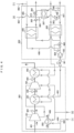
- Fig. 3 illustrates a system diagram of the heat recovery system.
- portions denoted by the same reference signs as those in Fig. 1 indicate the same or equivalent portions, and a description of the same portions as those in the first embodiment will be omitted.
- the temperature of hot water that is extracted can be more increased than in the water flowing method illustrated in the first embodiment, and the amount of recovered heat is increased.
- the amount of heat increases that enters the high-temperature fluid side of the auxiliary cooling heat exchanger 206 via the auxiliary cooling bypass path 406, consequently, the amount of heat received by the cooling water on the third cooling water path 405 also increases. For this reason, a larger flow rate of the cooling water of the supply water path 407 can be preheated via the preheating heat exchanger 207 than in the case of the first embodiment.
- the cooling water flows to the intercooler 201 prior to flowing to the aftercooler 202.
- a control valve 304 is installed on the bypass path 410.
- a check valve 305 is provided at the outlet of the auxiliary cooling heat exchanger 206 on the third cooling water path 405 to prevent the high-temperature cooling water of the first cooling water path 402 from flowing back to a third cooling water path 405 side.
- a fluid that is supplied to the outside through the supply water path 407 after heat recovery is also not limited to water, and various fluids are assumed to be used as the fluid.
- the fluid is not limited to supply water, and a "supply liquid" may be considered as the fluid.
- the first cooling water path and the third cooling water path have been described as being independent of each other for convenience; but as in the third embodiment, even when the path is configured such that the outside cooling tower is shared and the third cooling water path branches from the first cooling water path outside the heat recovery system to merge again with each other, the functions of the present invention are not affected.
Landscapes
- Engineering & Computer Science (AREA)
- Mechanical Engineering (AREA)
- General Engineering & Computer Science (AREA)
- Physics & Mathematics (AREA)
- Thermal Sciences (AREA)
- Chemical & Material Sciences (AREA)
- Combustion & Propulsion (AREA)
- Compressor (AREA)
- Heat-Pump Type And Storage Water Heaters (AREA)
- Fluid Mechanics (AREA)
- Heat-Exchange Devices With Radiators And Conduit Assemblies (AREA)
Applications Claiming Priority (2)
| Application Number | Priority Date | Filing Date | Title |
|---|---|---|---|
| JP2019169215 | 2019-09-18 | ||
| PCT/JP2020/028173 WO2021053965A1 (ja) | 2019-09-18 | 2020-07-20 | 熱回収装置 |
Publications (3)
| Publication Number | Publication Date |
|---|---|
| EP4033098A1 EP4033098A1 (en) | 2022-07-27 |
| EP4033098A4 EP4033098A4 (en) | 2024-02-21 |
| EP4033098B1 true EP4033098B1 (en) | 2025-04-09 |
Family
ID=74884189
Family Applications (1)
| Application Number | Title | Priority Date | Filing Date |
|---|---|---|---|
| EP20865648.8A Active EP4033098B1 (en) | 2019-09-18 | 2020-07-20 | Heat recovery device |
Country Status (5)
| Country | Link |
|---|---|
| US (1) | US12092113B2 (https=) |
| EP (1) | EP4033098B1 (https=) |
| JP (1) | JP7367040B2 (https=) |
| CN (1) | CN114375382B (https=) |
| WO (1) | WO2021053965A1 (https=) |
Families Citing this family (2)
| Publication number | Priority date | Publication date | Assignee | Title |
|---|---|---|---|---|
| WO2020195528A1 (ja) * | 2019-03-27 | 2020-10-01 | 株式会社日立産機システム | 圧縮機システム、及び、その制御方法 |
| JP7756828B1 (ja) * | 2025-04-04 | 2025-10-20 | 日鉄エンジニアリング株式会社 | 加熱装置、単位操作システム、及び二酸化炭素ガス回収システム |
Family Cites Families (17)
| Publication number | Priority date | Publication date | Assignee | Title |
|---|---|---|---|---|
| US3856493A (en) * | 1973-05-08 | 1974-12-24 | Dunham Bush Inc | Energy recovery system for oil injected screw compressors |
| JP2005030715A (ja) | 2003-07-09 | 2005-02-03 | Paloma Ind Ltd | 排熱回収給湯システム |
| DK1794510T3 (da) * | 2004-08-09 | 2012-05-21 | Carrier Corp | CO2 kølekredsløb med underkøling af det flydende kølemiddel med receiver-flashgassen samt fremgangsmåde til drift af dette |
| US7766077B2 (en) * | 2005-04-05 | 2010-08-03 | Omnitherm, Inc. | Self-contained modular heater |
| JP5484890B2 (ja) * | 2009-12-25 | 2014-05-07 | 三洋電機株式会社 | 冷凍装置 |
| BE1018598A3 (nl) * | 2010-01-25 | 2011-04-05 | Atlas Copco Airpower Nv | Werkwijze voor het recupereren van enrgie. |
| JP5632700B2 (ja) * | 2010-10-19 | 2014-11-26 | 三浦工業株式会社 | 熱回収システム |
| JP5636955B2 (ja) | 2010-12-27 | 2014-12-10 | 三菱日立パワーシステムズ株式会社 | 熱回収利用システム |
| GB2510547B (en) * | 2012-03-01 | 2016-04-27 | Waste Heat Recovery Ltd | Heat recovery |
| US10578339B2 (en) * | 2013-01-28 | 2020-03-03 | Hitachi Industrial Equipment Systems Co., Ltd. | Waste-heat recovery system in oil-cooled gas compressor |
| US9702358B2 (en) * | 2013-03-15 | 2017-07-11 | Ingersoll-Rand Company | Temperature control for compressor |
| KR101434908B1 (ko) * | 2013-05-23 | 2014-08-29 | 포스코에너지 주식회사 | 중저온 폐열을 활용한 난방 열원 또는 전기 생산 시스템, 및 그 제어방법 |
| JP2016079894A (ja) | 2014-10-17 | 2016-05-16 | 三浦工業株式会社 | 熱回収システム |
| DE102015213527A1 (de) * | 2015-07-17 | 2017-01-19 | Leybold Gmbh | Pumpensystem |
| JP6186530B1 (ja) | 2017-03-28 | 2017-08-23 | 東京瓦斯株式会社 | 燃料電池システム、制御装置、及びプログラム |
| DE102019102387A1 (de) * | 2019-01-30 | 2020-07-30 | Gardner Denver Deutschland Gmbh | Kühlungsanordnung und Verfahren zur Kühlung eines mindestens zweistufigen Drucklufterzeugers |
| EP3714962B1 (de) * | 2019-03-29 | 2021-12-15 | Kaeser Kompressoren SE | Druckluftstation |
-
2020
- 2020-07-20 CN CN202080063441.XA patent/CN114375382B/zh active Active
- 2020-07-20 JP JP2021546531A patent/JP7367040B2/ja active Active
- 2020-07-20 US US17/639,005 patent/US12092113B2/en active Active
- 2020-07-20 EP EP20865648.8A patent/EP4033098B1/en active Active
- 2020-07-20 WO PCT/JP2020/028173 patent/WO2021053965A1/ja not_active Ceased
Also Published As
| Publication number | Publication date |
|---|---|
| EP4033098A1 (en) | 2022-07-27 |
| US20220341426A1 (en) | 2022-10-27 |
| EP4033098A4 (en) | 2024-02-21 |
| JP7367040B2 (ja) | 2023-10-23 |
| CN114375382A (zh) | 2022-04-19 |
| JPWO2021053965A1 (https=) | 2021-03-25 |
| US12092113B2 (en) | 2024-09-17 |
| CN114375382B (zh) | 2023-10-24 |
| WO2021053965A1 (ja) | 2021-03-25 |
Similar Documents
| Publication | Publication Date | Title |
|---|---|---|
| US11859605B2 (en) | Compressor system, and control method for same | |
| KR101331925B1 (ko) | 선박의 폐열을 이용한 에너지 절감 장치 | |
| CN108779711A (zh) | 压缩空气贮藏发电装置 | |
| EP4033098B1 (en) | Heat recovery device | |
| US10907542B2 (en) | Compressed air energy storage power generation device | |
| JP7309593B2 (ja) | 排熱回収システム、及び、それに用いる気体圧縮機 | |
| JPWO2021053965A5 (https=) | ||
| JPS5833364Y2 (ja) | 圧縮機等の排熱回収装置 | |
| CN216897822U (zh) | 一种超高温单机双级热泵系统 | |
| JP5470064B2 (ja) | 2段圧縮装置 | |
| CN120320354B (zh) | 火储联合调频系统 | |
| KR101919696B1 (ko) | 복합 사이클 발전 플랜트 | |
| JP7757519B2 (ja) | ガス圧縮システム | |
| EP4722536A1 (en) | Gas compressor | |
| WO2025094431A1 (ja) | 廃熱回収システム、廃熱回収ユニット、及び廃熱回収方法 | |
| CN223193849U (zh) | 一种双路融合式储能液冷系统及交直流一体化储能设备 | |
| JP2026030376A (ja) | 空気圧縮システム | |
| JPH0160743B2 (https=) | ||
| US20240295214A1 (en) | Method for heat recovery in a compressor and a compressor | |
| CN120627061A (zh) | 一种防止火电机组最小流量阀汽蚀的给水泵再循环系统 | |
| JP2023166928A (ja) | 圧縮機システム | |
| CN118317569A (zh) | 一种面向高热源的组合式多级冷却装置和方法 | |
| JP2025097836A (ja) | エアコンプレッサおよび熱利用システム | |
| CN120413890A (zh) | 一种热管理系统、电能设备及车辆 | |
| CN115298417A (zh) | 多芯热回收增压冷却器 |
Legal Events
| Date | Code | Title | Description |
|---|---|---|---|
| STAA | Information on the status of an ep patent application or granted ep patent |
Free format text: STATUS: THE INTERNATIONAL PUBLICATION HAS BEEN MADE |
|
| PUAI | Public reference made under article 153(3) epc to a published international application that has entered the european phase |
Free format text: ORIGINAL CODE: 0009012 |
|
| STAA | Information on the status of an ep patent application or granted ep patent |
Free format text: STATUS: REQUEST FOR EXAMINATION WAS MADE |
|
| 17P | Request for examination filed |
Effective date: 20220329 |
|
| AK | Designated contracting states |
Kind code of ref document: A1 Designated state(s): AL AT BE BG CH CY CZ DE DK EE ES FI FR GB GR HR HU IE IS IT LI LT LU LV MC MK MT NL NO PL PT RO RS SE SI SK SM TR |
|
| DAV | Request for validation of the european patent (deleted) | ||
| DAX | Request for extension of the european patent (deleted) | ||
| A4 | Supplementary search report drawn up and despatched |
Effective date: 20240122 |
|
| RIC1 | Information provided on ipc code assigned before grant |
Ipc: F04B 39/12 20060101ALI20240116BHEP Ipc: F04B 23/00 20060101ALI20240116BHEP Ipc: F04C 29/04 20060101ALI20240116BHEP Ipc: F04C 23/00 20060101ALI20240116BHEP Ipc: F24H 1/00 20220101ALI20240116BHEP Ipc: F28F 27/02 20060101ALI20240116BHEP Ipc: F04B 39/06 20060101AFI20240116BHEP |
|
| GRAP | Despatch of communication of intention to grant a patent |
Free format text: ORIGINAL CODE: EPIDOSNIGR1 |
|
| STAA | Information on the status of an ep patent application or granted ep patent |
Free format text: STATUS: GRANT OF PATENT IS INTENDED |
|
| RIC1 | Information provided on ipc code assigned before grant |
Ipc: F04B 39/12 20060101ALI20241010BHEP Ipc: F04B 23/00 20060101ALI20241010BHEP Ipc: F04C 29/04 20060101ALI20241010BHEP Ipc: F04C 23/00 20060101ALI20241010BHEP Ipc: F24H 1/00 20220101ALI20241010BHEP Ipc: F28F 27/02 20060101ALI20241010BHEP Ipc: F04B 39/06 20060101AFI20241010BHEP |
|
| INTG | Intention to grant announced |
Effective date: 20241108 |
|
| GRAS | Grant fee paid |
Free format text: ORIGINAL CODE: EPIDOSNIGR3 |
|
| GRAA | (expected) grant |
Free format text: ORIGINAL CODE: 0009210 |
|
| STAA | Information on the status of an ep patent application or granted ep patent |
Free format text: STATUS: THE PATENT HAS BEEN GRANTED |
|
| AK | Designated contracting states |
Kind code of ref document: B1 Designated state(s): AL AT BE BG CH CY CZ DE DK EE ES FI FR GB GR HR HU IE IS IT LI LT LU LV MC MK MT NL NO PL PT RO RS SE SI SK SM TR |
|
| REG | Reference to a national code |
Ref country code: GB Ref legal event code: FG4D |
|
| REG | Reference to a national code |
Ref country code: CH Ref legal event code: EP |
|
| REG | Reference to a national code |
Ref country code: DE Ref legal event code: R096 Ref document number: 602020049283 Country of ref document: DE |
|
| REG | Reference to a national code |
Ref country code: IE Ref legal event code: FG4D |
|
| REG | Reference to a national code |
Ref country code: NL Ref legal event code: MP Effective date: 20250409 |
|
| PG25 | Lapsed in a contracting state [announced via postgrant information from national office to epo] |
Ref country code: NL Free format text: LAPSE BECAUSE OF FAILURE TO SUBMIT A TRANSLATION OF THE DESCRIPTION OR TO PAY THE FEE WITHIN THE PRESCRIBED TIME-LIMIT Effective date: 20250409 |
|
| REG | Reference to a national code |
Ref country code: AT Ref legal event code: MK05 Ref document number: 1783715 Country of ref document: AT Kind code of ref document: T Effective date: 20250409 |
|
| PG25 | Lapsed in a contracting state [announced via postgrant information from national office to epo] |
Ref country code: FI Free format text: LAPSE BECAUSE OF FAILURE TO SUBMIT A TRANSLATION OF THE DESCRIPTION OR TO PAY THE FEE WITHIN THE PRESCRIBED TIME-LIMIT Effective date: 20250409 Ref country code: PT Free format text: LAPSE BECAUSE OF FAILURE TO SUBMIT A TRANSLATION OF THE DESCRIPTION OR TO PAY THE FEE WITHIN THE PRESCRIBED TIME-LIMIT Effective date: 20250811 Ref country code: ES Free format text: LAPSE BECAUSE OF FAILURE TO SUBMIT A TRANSLATION OF THE DESCRIPTION OR TO PAY THE FEE WITHIN THE PRESCRIBED TIME-LIMIT Effective date: 20250409 |
|
| PGFP | Annual fee paid to national office [announced via postgrant information from national office to epo] |
Ref country code: DE Payment date: 20250731 Year of fee payment: 6 |
|
| REG | Reference to a national code |
Ref country code: LT Ref legal event code: MG9D |
|
| PG25 | Lapsed in a contracting state [announced via postgrant information from national office to epo] |
Ref country code: GR Free format text: LAPSE BECAUSE OF FAILURE TO SUBMIT A TRANSLATION OF THE DESCRIPTION OR TO PAY THE FEE WITHIN THE PRESCRIBED TIME-LIMIT Effective date: 20250710 Ref country code: NO Free format text: LAPSE BECAUSE OF FAILURE TO SUBMIT A TRANSLATION OF THE DESCRIPTION OR TO PAY THE FEE WITHIN THE PRESCRIBED TIME-LIMIT Effective date: 20250709 |
|
| PG25 | Lapsed in a contracting state [announced via postgrant information from national office to epo] |
Ref country code: PL Free format text: LAPSE BECAUSE OF FAILURE TO SUBMIT A TRANSLATION OF THE DESCRIPTION OR TO PAY THE FEE WITHIN THE PRESCRIBED TIME-LIMIT Effective date: 20250409 |
|
| PG25 | Lapsed in a contracting state [announced via postgrant information from national office to epo] |
Ref country code: BG Free format text: LAPSE BECAUSE OF FAILURE TO SUBMIT A TRANSLATION OF THE DESCRIPTION OR TO PAY THE FEE WITHIN THE PRESCRIBED TIME-LIMIT Effective date: 20250409 |
|
| PGFP | Annual fee paid to national office [announced via postgrant information from national office to epo] |
Ref country code: BE Payment date: 20250722 Year of fee payment: 6 Ref country code: GB Payment date: 20250724 Year of fee payment: 6 |
|
| PG25 | Lapsed in a contracting state [announced via postgrant information from national office to epo] |
Ref country code: HR Free format text: LAPSE BECAUSE OF FAILURE TO SUBMIT A TRANSLATION OF THE DESCRIPTION OR TO PAY THE FEE WITHIN THE PRESCRIBED TIME-LIMIT Effective date: 20250409 |
|
| PG25 | Lapsed in a contracting state [announced via postgrant information from national office to epo] |
Ref country code: AT Free format text: LAPSE BECAUSE OF FAILURE TO SUBMIT A TRANSLATION OF THE DESCRIPTION OR TO PAY THE FEE WITHIN THE PRESCRIBED TIME-LIMIT Effective date: 20250409 |
|
| PGFP | Annual fee paid to national office [announced via postgrant information from national office to epo] |
Ref country code: FR Payment date: 20250723 Year of fee payment: 6 |
|
| PG25 | Lapsed in a contracting state [announced via postgrant information from national office to epo] |
Ref country code: RS Free format text: LAPSE BECAUSE OF FAILURE TO SUBMIT A TRANSLATION OF THE DESCRIPTION OR TO PAY THE FEE WITHIN THE PRESCRIBED TIME-LIMIT Effective date: 20250709 |
|
| PG25 | Lapsed in a contracting state [announced via postgrant information from national office to epo] |
Ref country code: IS Free format text: LAPSE BECAUSE OF FAILURE TO SUBMIT A TRANSLATION OF THE DESCRIPTION OR TO PAY THE FEE WITHIN THE PRESCRIBED TIME-LIMIT Effective date: 20250809 |
|
| PG25 | Lapsed in a contracting state [announced via postgrant information from national office to epo] |
Ref country code: LV Free format text: LAPSE BECAUSE OF FAILURE TO SUBMIT A TRANSLATION OF THE DESCRIPTION OR TO PAY THE FEE WITHIN THE PRESCRIBED TIME-LIMIT Effective date: 20250409 |
|
| REG | Reference to a national code |
Ref country code: DE Ref legal event code: R097 Ref document number: 602020049283 Country of ref document: DE |
|
| PG25 | Lapsed in a contracting state [announced via postgrant information from national office to epo] |
Ref country code: SM Free format text: LAPSE BECAUSE OF FAILURE TO SUBMIT A TRANSLATION OF THE DESCRIPTION OR TO PAY THE FEE WITHIN THE PRESCRIBED TIME-LIMIT Effective date: 20250409 Ref country code: DK Free format text: LAPSE BECAUSE OF FAILURE TO SUBMIT A TRANSLATION OF THE DESCRIPTION OR TO PAY THE FEE WITHIN THE PRESCRIBED TIME-LIMIT Effective date: 20250409 |
|
| PG25 | Lapsed in a contracting state [announced via postgrant information from national office to epo] |
Ref country code: CZ Free format text: LAPSE BECAUSE OF FAILURE TO SUBMIT A TRANSLATION OF THE DESCRIPTION OR TO PAY THE FEE WITHIN THE PRESCRIBED TIME-LIMIT Effective date: 20250409 |
|
| PG25 | Lapsed in a contracting state [announced via postgrant information from national office to epo] |
Ref country code: EE Free format text: LAPSE BECAUSE OF FAILURE TO SUBMIT A TRANSLATION OF THE DESCRIPTION OR TO PAY THE FEE WITHIN THE PRESCRIBED TIME-LIMIT Effective date: 20250409 |
|
| PG25 | Lapsed in a contracting state [announced via postgrant information from national office to epo] |
Ref country code: SK Free format text: LAPSE BECAUSE OF FAILURE TO SUBMIT A TRANSLATION OF THE DESCRIPTION OR TO PAY THE FEE WITHIN THE PRESCRIBED TIME-LIMIT Effective date: 20250409 |
|
| PG25 | Lapsed in a contracting state [announced via postgrant information from national office to epo] |
Ref country code: IT Free format text: LAPSE BECAUSE OF FAILURE TO SUBMIT A TRANSLATION OF THE DESCRIPTION OR TO PAY THE FEE WITHIN THE PRESCRIBED TIME-LIMIT Effective date: 20250409 |
|
| PG25 | Lapsed in a contracting state [announced via postgrant information from national office to epo] |
Ref country code: RO Free format text: LAPSE BECAUSE OF FAILURE TO SUBMIT A TRANSLATION OF THE DESCRIPTION OR TO PAY THE FEE WITHIN THE PRESCRIBED TIME-LIMIT Effective date: 20250409 |
|
| PLBE | No opposition filed within time limit |
Free format text: ORIGINAL CODE: 0009261 |
|
| STAA | Information on the status of an ep patent application or granted ep patent |
Free format text: STATUS: NO OPPOSITION FILED WITHIN TIME LIMIT |
|
| REG | Reference to a national code |
Ref country code: CH Ref legal event code: L10 Free format text: ST27 STATUS EVENT CODE: U-0-0-L10-L00 (AS PROVIDED BY THE NATIONAL OFFICE) Effective date: 20260218 |
|
| REG | Reference to a national code |
Ref country code: CH Ref legal event code: H13 Free format text: ST27 STATUS EVENT CODE: U-0-0-H10-H13 (AS PROVIDED BY THE NATIONAL OFFICE) Effective date: 20260224 |
|
| PG25 | Lapsed in a contracting state [announced via postgrant information from national office to epo] |
Ref country code: LU Free format text: LAPSE BECAUSE OF NON-PAYMENT OF DUE FEES Effective date: 20250720 |
|
| 26N | No opposition filed |
Effective date: 20260112 |
|
| PG25 | Lapsed in a contracting state [announced via postgrant information from national office to epo] |
Ref country code: CH Free format text: LAPSE BECAUSE OF NON-PAYMENT OF DUE FEES Effective date: 20250731 |