EP4032737B1 - Hybridfahrzeug und steuerungsverfahren und -system nach ausfall der hybridfahrzeugbatterie - Google Patents
Hybridfahrzeug und steuerungsverfahren und -system nach ausfall der hybridfahrzeugbatterie Download PDFInfo
- Publication number
- EP4032737B1 EP4032737B1 EP20955472.4A EP20955472A EP4032737B1 EP 4032737 B1 EP4032737 B1 EP 4032737B1 EP 20955472 A EP20955472 A EP 20955472A EP 4032737 B1 EP4032737 B1 EP 4032737B1
- Authority
- EP
- European Patent Office
- Prior art keywords
- motor
- voltage
- engine
- control
- control unit
- Prior art date
- Legal status (The legal status is an assumption and is not a legal conclusion. Google has not performed a legal analysis and makes no representation as to the accuracy of the status listed.)
- Active
Links
Images


Classifications
-
- B—PERFORMING OPERATIONS; TRANSPORTING
- B60—VEHICLES IN GENERAL
- B60L—PROPULSION OF ELECTRICALLY-PROPELLED VEHICLES; SUPPLYING ELECTRIC POWER FOR AUXILIARY EQUIPMENT OF ELECTRICALLY-PROPELLED VEHICLES; ELECTRODYNAMIC BRAKE SYSTEMS FOR VEHICLES IN GENERAL; MAGNETIC SUSPENSION OR LEVITATION FOR VEHICLES; MONITORING OPERATING VARIABLES OF ELECTRICALLY-PROPELLED VEHICLES; ELECTRIC SAFETY DEVICES FOR ELECTRICALLY-PROPELLED VEHICLES
- B60L3/00—Electric devices on electrically-propelled vehicles for safety purposes; Monitoring operating variables, e.g. speed, deceleration or energy consumption
- B60L3/0023—Detecting, eliminating, remedying or compensating for drive train abnormalities, e.g. failures within the drive train
- B60L3/0046—Detecting, eliminating, remedying or compensating for drive train abnormalities, e.g. failures within the drive train relating to electric energy storage systems, e.g. batteries or capacitors
-
- B—PERFORMING OPERATIONS; TRANSPORTING
- B60—VEHICLES IN GENERAL
- B60K—ARRANGEMENT OR MOUNTING OF PROPULSION UNITS OR OF TRANSMISSIONS IN VEHICLES; ARRANGEMENT OR MOUNTING OF PLURAL DIVERSE PRIME-MOVERS IN VEHICLES; AUXILIARY DRIVES FOR VEHICLES; INSTRUMENTATION OR DASHBOARDS FOR VEHICLES; ARRANGEMENTS IN CONNECTION WITH COOLING, AIR INTAKE, GAS EXHAUST OR FUEL SUPPLY OF PROPULSION UNITS IN VEHICLES
- B60K6/00—Arrangement or mounting of plural diverse prime-movers for mutual or common propulsion, e.g. hybrid propulsion systems comprising electric motors and internal combustion engines
- B60K6/20—Arrangement or mounting of plural diverse prime-movers for mutual or common propulsion, e.g. hybrid propulsion systems comprising electric motors and internal combustion engines the prime-movers consisting of electric motors and internal combustion engines, e.g. HEVs
- B60K6/22—Arrangement or mounting of plural diverse prime-movers for mutual or common propulsion, e.g. hybrid propulsion systems comprising electric motors and internal combustion engines the prime-movers consisting of electric motors and internal combustion engines, e.g. HEVs characterised by apparatus, components or means specially adapted for HEVs
- B60K6/26—Arrangement or mounting of plural diverse prime-movers for mutual or common propulsion, e.g. hybrid propulsion systems comprising electric motors and internal combustion engines the prime-movers consisting of electric motors and internal combustion engines, e.g. HEVs characterised by apparatus, components or means specially adapted for HEVs characterised by the motors or the generators
-
- B—PERFORMING OPERATIONS; TRANSPORTING
- B60—VEHICLES IN GENERAL
- B60K—ARRANGEMENT OR MOUNTING OF PROPULSION UNITS OR OF TRANSMISSIONS IN VEHICLES; ARRANGEMENT OR MOUNTING OF PLURAL DIVERSE PRIME-MOVERS IN VEHICLES; AUXILIARY DRIVES FOR VEHICLES; INSTRUMENTATION OR DASHBOARDS FOR VEHICLES; ARRANGEMENTS IN CONNECTION WITH COOLING, AIR INTAKE, GAS EXHAUST OR FUEL SUPPLY OF PROPULSION UNITS IN VEHICLES
- B60K6/00—Arrangement or mounting of plural diverse prime-movers for mutual or common propulsion, e.g. hybrid propulsion systems comprising electric motors and internal combustion engines
- B60K6/20—Arrangement or mounting of plural diverse prime-movers for mutual or common propulsion, e.g. hybrid propulsion systems comprising electric motors and internal combustion engines the prime-movers consisting of electric motors and internal combustion engines, e.g. HEVs
- B60K6/22—Arrangement or mounting of plural diverse prime-movers for mutual or common propulsion, e.g. hybrid propulsion systems comprising electric motors and internal combustion engines the prime-movers consisting of electric motors and internal combustion engines, e.g. HEVs characterised by apparatus, components or means specially adapted for HEVs
- B60K6/38—Arrangement or mounting of plural diverse prime-movers for mutual or common propulsion, e.g. hybrid propulsion systems comprising electric motors and internal combustion engines the prime-movers consisting of electric motors and internal combustion engines, e.g. HEVs characterised by apparatus, components or means specially adapted for HEVs characterised by the driveline clutches
- B60K6/387—Actuated clutches, i.e. clutches engaged or disengaged by electric, hydraulic or mechanical actuating means
-
- B—PERFORMING OPERATIONS; TRANSPORTING
- B60—VEHICLES IN GENERAL
- B60K—ARRANGEMENT OR MOUNTING OF PROPULSION UNITS OR OF TRANSMISSIONS IN VEHICLES; ARRANGEMENT OR MOUNTING OF PLURAL DIVERSE PRIME-MOVERS IN VEHICLES; AUXILIARY DRIVES FOR VEHICLES; INSTRUMENTATION OR DASHBOARDS FOR VEHICLES; ARRANGEMENTS IN CONNECTION WITH COOLING, AIR INTAKE, GAS EXHAUST OR FUEL SUPPLY OF PROPULSION UNITS IN VEHICLES
- B60K6/00—Arrangement or mounting of plural diverse prime-movers for mutual or common propulsion, e.g. hybrid propulsion systems comprising electric motors and internal combustion engines
- B60K6/20—Arrangement or mounting of plural diverse prime-movers for mutual or common propulsion, e.g. hybrid propulsion systems comprising electric motors and internal combustion engines the prime-movers consisting of electric motors and internal combustion engines, e.g. HEVs
- B60K6/42—Arrangement or mounting of plural diverse prime-movers for mutual or common propulsion, e.g. hybrid propulsion systems comprising electric motors and internal combustion engines the prime-movers consisting of electric motors and internal combustion engines, e.g. HEVs characterised by the architecture of the hybrid electric vehicle
- B60K6/48—Parallel type
-
- B—PERFORMING OPERATIONS; TRANSPORTING
- B60—VEHICLES IN GENERAL
- B60K—ARRANGEMENT OR MOUNTING OF PROPULSION UNITS OR OF TRANSMISSIONS IN VEHICLES; ARRANGEMENT OR MOUNTING OF PLURAL DIVERSE PRIME-MOVERS IN VEHICLES; AUXILIARY DRIVES FOR VEHICLES; INSTRUMENTATION OR DASHBOARDS FOR VEHICLES; ARRANGEMENTS IN CONNECTION WITH COOLING, AIR INTAKE, GAS EXHAUST OR FUEL SUPPLY OF PROPULSION UNITS IN VEHICLES
- B60K6/00—Arrangement or mounting of plural diverse prime-movers for mutual or common propulsion, e.g. hybrid propulsion systems comprising electric motors and internal combustion engines
- B60K6/20—Arrangement or mounting of plural diverse prime-movers for mutual or common propulsion, e.g. hybrid propulsion systems comprising electric motors and internal combustion engines the prime-movers consisting of electric motors and internal combustion engines, e.g. HEVs
- B60K6/50—Architecture of the driveline characterised by arrangement or kind of transmission units
- B60K6/54—Transmission for changing ratio
- B60K6/547—Transmission for changing ratio the transmission being a stepped gearing
-
- B—PERFORMING OPERATIONS; TRANSPORTING
- B60—VEHICLES IN GENERAL
- B60L—PROPULSION OF ELECTRICALLY-PROPELLED VEHICLES; SUPPLYING ELECTRIC POWER FOR AUXILIARY EQUIPMENT OF ELECTRICALLY-PROPELLED VEHICLES; ELECTRODYNAMIC BRAKE SYSTEMS FOR VEHICLES IN GENERAL; MAGNETIC SUSPENSION OR LEVITATION FOR VEHICLES; MONITORING OPERATING VARIABLES OF ELECTRICALLY-PROPELLED VEHICLES; ELECTRIC SAFETY DEVICES FOR ELECTRICALLY-PROPELLED VEHICLES
- B60L3/00—Electric devices on electrically-propelled vehicles for safety purposes; Monitoring operating variables, e.g. speed, deceleration or energy consumption
- B60L3/0023—Detecting, eliminating, remedying or compensating for drive train abnormalities, e.g. failures within the drive train
-
- B—PERFORMING OPERATIONS; TRANSPORTING
- B60—VEHICLES IN GENERAL
- B60L—PROPULSION OF ELECTRICALLY-PROPELLED VEHICLES; SUPPLYING ELECTRIC POWER FOR AUXILIARY EQUIPMENT OF ELECTRICALLY-PROPELLED VEHICLES; ELECTRODYNAMIC BRAKE SYSTEMS FOR VEHICLES IN GENERAL; MAGNETIC SUSPENSION OR LEVITATION FOR VEHICLES; MONITORING OPERATING VARIABLES OF ELECTRICALLY-PROPELLED VEHICLES; ELECTRIC SAFETY DEVICES FOR ELECTRICALLY-PROPELLED VEHICLES
- B60L3/00—Electric devices on electrically-propelled vehicles for safety purposes; Monitoring operating variables, e.g. speed, deceleration or energy consumption
- B60L3/04—Cutting off the power supply under fault conditions
-
- B—PERFORMING OPERATIONS; TRANSPORTING
- B60—VEHICLES IN GENERAL
- B60L—PROPULSION OF ELECTRICALLY-PROPELLED VEHICLES; SUPPLYING ELECTRIC POWER FOR AUXILIARY EQUIPMENT OF ELECTRICALLY-PROPELLED VEHICLES; ELECTRODYNAMIC BRAKE SYSTEMS FOR VEHICLES IN GENERAL; MAGNETIC SUSPENSION OR LEVITATION FOR VEHICLES; MONITORING OPERATING VARIABLES OF ELECTRICALLY-PROPELLED VEHICLES; ELECTRIC SAFETY DEVICES FOR ELECTRICALLY-PROPELLED VEHICLES
- B60L50/00—Electric propulsion with power supplied within the vehicle
- B60L50/10—Electric propulsion with power supplied within the vehicle using propulsion power supplied by engine-driven generators, e.g. generators driven by combustion engines
- B60L50/13—Electric propulsion with power supplied within the vehicle using propulsion power supplied by engine-driven generators, e.g. generators driven by combustion engines using AC generators and AC motors
-
- B—PERFORMING OPERATIONS; TRANSPORTING
- B60—VEHICLES IN GENERAL
- B60L—PROPULSION OF ELECTRICALLY-PROPELLED VEHICLES; SUPPLYING ELECTRIC POWER FOR AUXILIARY EQUIPMENT OF ELECTRICALLY-PROPELLED VEHICLES; ELECTRODYNAMIC BRAKE SYSTEMS FOR VEHICLES IN GENERAL; MAGNETIC SUSPENSION OR LEVITATION FOR VEHICLES; MONITORING OPERATING VARIABLES OF ELECTRICALLY-PROPELLED VEHICLES; ELECTRIC SAFETY DEVICES FOR ELECTRICALLY-PROPELLED VEHICLES
- B60L50/00—Electric propulsion with power supplied within the vehicle
- B60L50/10—Electric propulsion with power supplied within the vehicle using propulsion power supplied by engine-driven generators, e.g. generators driven by combustion engines
- B60L50/16—Electric propulsion with power supplied within the vehicle using propulsion power supplied by engine-driven generators, e.g. generators driven by combustion engines with provision for separate direct mechanical propulsion
-
- B—PERFORMING OPERATIONS; TRANSPORTING
- B60—VEHICLES IN GENERAL
- B60L—PROPULSION OF ELECTRICALLY-PROPELLED VEHICLES; SUPPLYING ELECTRIC POWER FOR AUXILIARY EQUIPMENT OF ELECTRICALLY-PROPELLED VEHICLES; ELECTRODYNAMIC BRAKE SYSTEMS FOR VEHICLES IN GENERAL; MAGNETIC SUSPENSION OR LEVITATION FOR VEHICLES; MONITORING OPERATING VARIABLES OF ELECTRICALLY-PROPELLED VEHICLES; ELECTRIC SAFETY DEVICES FOR ELECTRICALLY-PROPELLED VEHICLES
- B60L50/00—Electric propulsion with power supplied within the vehicle
- B60L50/50—Electric propulsion with power supplied within the vehicle using propulsion power supplied by batteries or fuel cells
- B60L50/60—Electric propulsion with power supplied within the vehicle using propulsion power supplied by batteries or fuel cells using power supplied by batteries
- B60L50/61—Electric propulsion with power supplied within the vehicle using propulsion power supplied by batteries or fuel cells using power supplied by batteries by batteries charged by engine-driven generators, e.g. series hybrid electric vehicles
-
- B—PERFORMING OPERATIONS; TRANSPORTING
- B60—VEHICLES IN GENERAL
- B60W—CONJOINT CONTROL OF VEHICLE SUB-UNITS OF DIFFERENT TYPE OR DIFFERENT FUNCTION; CONTROL SYSTEMS SPECIALLY ADAPTED FOR HYBRID VEHICLES; ROAD VEHICLE DRIVE CONTROL SYSTEMS FOR PURPOSES NOT RELATED TO THE CONTROL OF A PARTICULAR SUB-UNIT
- B60W10/00—Conjoint control of vehicle sub-units of different type or different function
- B60W10/04—Conjoint control of vehicle sub-units of different type or different function including control of propulsion units
- B60W10/06—Conjoint control of vehicle sub-units of different type or different function including control of propulsion units including control of combustion engines
-
- B—PERFORMING OPERATIONS; TRANSPORTING
- B60—VEHICLES IN GENERAL
- B60W—CONJOINT CONTROL OF VEHICLE SUB-UNITS OF DIFFERENT TYPE OR DIFFERENT FUNCTION; CONTROL SYSTEMS SPECIALLY ADAPTED FOR HYBRID VEHICLES; ROAD VEHICLE DRIVE CONTROL SYSTEMS FOR PURPOSES NOT RELATED TO THE CONTROL OF A PARTICULAR SUB-UNIT
- B60W10/00—Conjoint control of vehicle sub-units of different type or different function
- B60W10/04—Conjoint control of vehicle sub-units of different type or different function including control of propulsion units
- B60W10/08—Conjoint control of vehicle sub-units of different type or different function including control of propulsion units including control of electric propulsion units, e.g. motors or generators
-
- B—PERFORMING OPERATIONS; TRANSPORTING
- B60—VEHICLES IN GENERAL
- B60W—CONJOINT CONTROL OF VEHICLE SUB-UNITS OF DIFFERENT TYPE OR DIFFERENT FUNCTION; CONTROL SYSTEMS SPECIALLY ADAPTED FOR HYBRID VEHICLES; ROAD VEHICLE DRIVE CONTROL SYSTEMS FOR PURPOSES NOT RELATED TO THE CONTROL OF A PARTICULAR SUB-UNIT
- B60W10/00—Conjoint control of vehicle sub-units of different type or different function
- B60W10/10—Conjoint control of vehicle sub-units of different type or different function including control of change-speed gearings
- B60W10/11—Stepped gearings
-
- B—PERFORMING OPERATIONS; TRANSPORTING
- B60—VEHICLES IN GENERAL
- B60W—CONJOINT CONTROL OF VEHICLE SUB-UNITS OF DIFFERENT TYPE OR DIFFERENT FUNCTION; CONTROL SYSTEMS SPECIALLY ADAPTED FOR HYBRID VEHICLES; ROAD VEHICLE DRIVE CONTROL SYSTEMS FOR PURPOSES NOT RELATED TO THE CONTROL OF A PARTICULAR SUB-UNIT
- B60W10/00—Conjoint control of vehicle sub-units of different type or different function
- B60W10/24—Conjoint control of vehicle sub-units of different type or different function including control of energy storage means
- B60W10/26—Conjoint control of vehicle sub-units of different type or different function including control of energy storage means for electrical energy, e.g. batteries or capacitors
-
- B—PERFORMING OPERATIONS; TRANSPORTING
- B60—VEHICLES IN GENERAL
- B60W—CONJOINT CONTROL OF VEHICLE SUB-UNITS OF DIFFERENT TYPE OR DIFFERENT FUNCTION; CONTROL SYSTEMS SPECIALLY ADAPTED FOR HYBRID VEHICLES; ROAD VEHICLE DRIVE CONTROL SYSTEMS FOR PURPOSES NOT RELATED TO THE CONTROL OF A PARTICULAR SUB-UNIT
- B60W20/00—Control systems specially adapted for hybrid vehicles
- B60W20/50—Control strategies for responding to system failures, e.g. for fault diagnosis, failsafe operation or limp mode
-
- B—PERFORMING OPERATIONS; TRANSPORTING
- B60—VEHICLES IN GENERAL
- B60K—ARRANGEMENT OR MOUNTING OF PROPULSION UNITS OR OF TRANSMISSIONS IN VEHICLES; ARRANGEMENT OR MOUNTING OF PLURAL DIVERSE PRIME-MOVERS IN VEHICLES; AUXILIARY DRIVES FOR VEHICLES; INSTRUMENTATION OR DASHBOARDS FOR VEHICLES; ARRANGEMENTS IN CONNECTION WITH COOLING, AIR INTAKE, GAS EXHAUST OR FUEL SUPPLY OF PROPULSION UNITS IN VEHICLES
- B60K6/00—Arrangement or mounting of plural diverse prime-movers for mutual or common propulsion, e.g. hybrid propulsion systems comprising electric motors and internal combustion engines
- B60K6/20—Arrangement or mounting of plural diverse prime-movers for mutual or common propulsion, e.g. hybrid propulsion systems comprising electric motors and internal combustion engines the prime-movers consisting of electric motors and internal combustion engines, e.g. HEVs
- B60K6/42—Arrangement or mounting of plural diverse prime-movers for mutual or common propulsion, e.g. hybrid propulsion systems comprising electric motors and internal combustion engines the prime-movers consisting of electric motors and internal combustion engines, e.g. HEVs characterised by the architecture of the hybrid electric vehicle
- B60K6/48—Parallel type
- B60K2006/4825—Electric machine connected or connectable to gearbox input shaft
-
- B—PERFORMING OPERATIONS; TRANSPORTING
- B60—VEHICLES IN GENERAL
- B60L—PROPULSION OF ELECTRICALLY-PROPELLED VEHICLES; SUPPLYING ELECTRIC POWER FOR AUXILIARY EQUIPMENT OF ELECTRICALLY-PROPELLED VEHICLES; ELECTRODYNAMIC BRAKE SYSTEMS FOR VEHICLES IN GENERAL; MAGNETIC SUSPENSION OR LEVITATION FOR VEHICLES; MONITORING OPERATING VARIABLES OF ELECTRICALLY-PROPELLED VEHICLES; ELECTRIC SAFETY DEVICES FOR ELECTRICALLY-PROPELLED VEHICLES
- B60L2240/00—Control parameters of input or output; Target parameters
- B60L2240/40—Drive Train control parameters
- B60L2240/42—Drive Train control parameters related to electric machines
- B60L2240/427—Voltage
-
- B—PERFORMING OPERATIONS; TRANSPORTING
- B60—VEHICLES IN GENERAL
- B60W—CONJOINT CONTROL OF VEHICLE SUB-UNITS OF DIFFERENT TYPE OR DIFFERENT FUNCTION; CONTROL SYSTEMS SPECIALLY ADAPTED FOR HYBRID VEHICLES; ROAD VEHICLE DRIVE CONTROL SYSTEMS FOR PURPOSES NOT RELATED TO THE CONTROL OF A PARTICULAR SUB-UNIT
- B60W2540/00—Input parameters relating to occupants
- B60W2540/10—Accelerator pedal position
-
- B—PERFORMING OPERATIONS; TRANSPORTING
- B60—VEHICLES IN GENERAL
- B60W—CONJOINT CONTROL OF VEHICLE SUB-UNITS OF DIFFERENT TYPE OR DIFFERENT FUNCTION; CONTROL SYSTEMS SPECIALLY ADAPTED FOR HYBRID VEHICLES; ROAD VEHICLE DRIVE CONTROL SYSTEMS FOR PURPOSES NOT RELATED TO THE CONTROL OF A PARTICULAR SUB-UNIT
- B60W2710/00—Output or target parameters relating to a particular sub-units
- B60W2710/02—Clutches
- B60W2710/021—Clutch engagement state
-
- B—PERFORMING OPERATIONS; TRANSPORTING
- B60—VEHICLES IN GENERAL
- B60W—CONJOINT CONTROL OF VEHICLE SUB-UNITS OF DIFFERENT TYPE OR DIFFERENT FUNCTION; CONTROL SYSTEMS SPECIALLY ADAPTED FOR HYBRID VEHICLES; ROAD VEHICLE DRIVE CONTROL SYSTEMS FOR PURPOSES NOT RELATED TO THE CONTROL OF A PARTICULAR SUB-UNIT
- B60W2710/00—Output or target parameters relating to a particular sub-units
- B60W2710/06—Combustion engines, Gas turbines
- B60W2710/0666—Engine torque
-
- B—PERFORMING OPERATIONS; TRANSPORTING
- B60—VEHICLES IN GENERAL
- B60W—CONJOINT CONTROL OF VEHICLE SUB-UNITS OF DIFFERENT TYPE OR DIFFERENT FUNCTION; CONTROL SYSTEMS SPECIALLY ADAPTED FOR HYBRID VEHICLES; ROAD VEHICLE DRIVE CONTROL SYSTEMS FOR PURPOSES NOT RELATED TO THE CONTROL OF A PARTICULAR SUB-UNIT
- B60W2710/00—Output or target parameters relating to a particular sub-units
- B60W2710/08—Electric propulsion units
- B60W2710/081—Speed
-
- B—PERFORMING OPERATIONS; TRANSPORTING
- B60—VEHICLES IN GENERAL
- B60W—CONJOINT CONTROL OF VEHICLE SUB-UNITS OF DIFFERENT TYPE OR DIFFERENT FUNCTION; CONTROL SYSTEMS SPECIALLY ADAPTED FOR HYBRID VEHICLES; ROAD VEHICLE DRIVE CONTROL SYSTEMS FOR PURPOSES NOT RELATED TO THE CONTROL OF A PARTICULAR SUB-UNIT
- B60W2710/00—Output or target parameters relating to a particular sub-units
- B60W2710/08—Electric propulsion units
- B60W2710/083—Torque
-
- B—PERFORMING OPERATIONS; TRANSPORTING
- B60—VEHICLES IN GENERAL
- B60W—CONJOINT CONTROL OF VEHICLE SUB-UNITS OF DIFFERENT TYPE OR DIFFERENT FUNCTION; CONTROL SYSTEMS SPECIALLY ADAPTED FOR HYBRID VEHICLES; ROAD VEHICLE DRIVE CONTROL SYSTEMS FOR PURPOSES NOT RELATED TO THE CONTROL OF A PARTICULAR SUB-UNIT
- B60W2710/00—Output or target parameters relating to a particular sub-units
- B60W2710/10—Change speed gearings
- B60W2710/1005—Transmission ratio engaged
-
- B—PERFORMING OPERATIONS; TRANSPORTING
- B60—VEHICLES IN GENERAL
- B60W—CONJOINT CONTROL OF VEHICLE SUB-UNITS OF DIFFERENT TYPE OR DIFFERENT FUNCTION; CONTROL SYSTEMS SPECIALLY ADAPTED FOR HYBRID VEHICLES; ROAD VEHICLE DRIVE CONTROL SYSTEMS FOR PURPOSES NOT RELATED TO THE CONTROL OF A PARTICULAR SUB-UNIT
- B60W2710/00—Output or target parameters relating to a particular sub-units
- B60W2710/24—Energy storage means
- B60W2710/242—Energy storage means for electrical energy
- B60W2710/248—Current for loading or unloading
-
- B—PERFORMING OPERATIONS; TRANSPORTING
- B60—VEHICLES IN GENERAL
- B60W—CONJOINT CONTROL OF VEHICLE SUB-UNITS OF DIFFERENT TYPE OR DIFFERENT FUNCTION; CONTROL SYSTEMS SPECIALLY ADAPTED FOR HYBRID VEHICLES; ROAD VEHICLE DRIVE CONTROL SYSTEMS FOR PURPOSES NOT RELATED TO THE CONTROL OF A PARTICULAR SUB-UNIT
- B60W2710/00—Output or target parameters relating to a particular sub-units
- B60W2710/30—Auxiliary equipments
- B60W2710/305—Auxiliary equipments target power to auxiliaries
-
- Y—GENERAL TAGGING OF NEW TECHNOLOGICAL DEVELOPMENTS; GENERAL TAGGING OF CROSS-SECTIONAL TECHNOLOGIES SPANNING OVER SEVERAL SECTIONS OF THE IPC; TECHNICAL SUBJECTS COVERED BY FORMER USPC CROSS-REFERENCE ART COLLECTIONS [XRACs] AND DIGESTS
- Y02—TECHNOLOGIES OR APPLICATIONS FOR MITIGATION OR ADAPTATION AGAINST CLIMATE CHANGE
- Y02T—CLIMATE CHANGE MITIGATION TECHNOLOGIES RELATED TO TRANSPORTATION
- Y02T10/00—Road transport of goods or passengers
- Y02T10/60—Other road transportation technologies with climate change mitigation effect
- Y02T10/62—Hybrid vehicles
Definitions
- the present invention relates to the technical field of vehicles, and particularly to a control method and a control system for a hybrid electric vehicle after a battery failure, and a hybrid electric vehicle including the control system.
- Hybrid technology is a key technology to energy saving and emission reduction of vehicles. Based on the position of a motor relative to a conventional power system, single-motor hybrid power systems are classified as follows: a P0 configuration, a P1 configuration, a P2 configuration, a P2.5 configuration, a P3 configuration and a P4 configuration.
- a P0 configuration a P0 configuration
- a P1 configuration a P2 configuration
- a P2.5 configuration a P3 configuration
- P4 configuration a P4 configuration.
- the industry mainly conducts research on the control of a hybrid power system on the basis of normal operation of a high-voltage battery (power battery), whereas rarely researches the control strategy for an abnormality of the high-voltage battery.
- Prior art document CN110877607 discloses a self-generating limp system and method for a hybrid electric vehicle.
- the method comprises: setting electric appliance loads with the current fluctuation value larger than a set current fluctuation threshold value during opening/closing in whole vehicle loads to be R1, R2,..., Rn; when the 48V lithium battery has a fault, the lithium battery is charged, firstly, requesting an IBSG motor to enter an idle mode; then pre-charging and adjusting the idling speed of the engine are carried out; and after the voltage in the IBSG motor loop and the rotating speed of the IBSG motor meet the requirements, requesting the IBSG motor to enter a power generation mode to generate power, forbidding R1, R2,..., Rn to be switched on/off, and then converting the output voltage of the IBSG motor to charge the storage battery.
- the present invention is disclosed to provide a control method and a control system for overcoming the problem or at least partly solving the problem of a hybrid electric vehicle after a battery failure and a hybrid electric vehicle including the control system.
- One object of the present invention is to provide a control method and system for a hybrid electric vehicle after a battery failure to conduct coordination control on a power battery, a motor, a transmission and an engine before a relay of the power battery is disengaged, to enable the motor to smoothly enter into a voltage control mode and operate stably.
- a further object of the present invention is to conduct voltage control with different motor target voltages before and after the relay is disengaged, to further reduce voltage fluctuation of the motor, and enable the motor to operate stably.
- a yet further object of the present invention is to take the difference between a driver request torque and an actual torque of the motor as an engine request torque, to enable the engine to meet a driver request and a low-voltage system charge request of a vehicle, so that a hybrid electric vehicle can still continuously operate like a conventional vehicle even after a battery failure, and the security and robustness of the vehicle are improved.
- the present invention provides a control method for a hybrid electric vehicle after a battery failure, which is as defined in claims 1 to 7.
- the present invention further provides a control system for a hybrid electric vehicle after a battery failure, which is as defined in claims 8-12.
- the present invention further provides a hybrid electric vehicle, including the control system for a hybrid electric vehicle after a battery failure of any one of the embodiments.
- the control method and system for the hybrid electric vehicle after the battery failure after monitoring that a failure occurs in a power battery, first judge whether the failure is a specific type of failure under which a motor is capable of conducting voltage control.
- the failure of the power battery is the specific type of failure
- the power battery, an engine, a transmission and a motor of the hybrid electric vehicle are coordinated and controlled, to enable operation states thereof to meet a preset voltage control entering condition, and then the motor is controlled to enter into the voltage control mode.
- the motor can enter into voltage control and operate stably, thus avoiding problems of overtemperature of a battery, serious voltage fluctuation and the like caused by direct voltage control on the motor after a power battery failure.
- the difference between the driver request torque and the actual torque of the motor is taken as the engine request torque, to enable the output torque of the engine to meet the wheel driving demand and the low-voltage system charge demand of the hybrid electric vehicle, and thus after the failure occurs in the power battery, the engine is still capable of meeting the driver request and the low-voltage system charge request of the vehicle, so that the hybrid electric vehicle is still capable of continuously operating like a conventional vehicle, and the security and robustness of the vehicle are improved.
- a hybrid power system currently has the following main configurations: a P2 configuration, a P2.5 configuration and a P3 configuration.
- the P2.5 configuration has the characteristics that a motor and a dual clutch transmission are integrated, the motor is connected to an even axis of the dual clutch transmission, the motor is positioned behind a clutch and before a gear, and a step gear is arranged between the transmission axis and the motor to increase the rotation speed of the motor.
- the hybrid power system of the P2.5 configuration has the advantages of simplified structure, simplified material, reduced weight, simple control, motor and clutch gearing thus reducing the load, high system efficiency, significant fuel saving effect, and the like.
- FIG. 1 shows a structural schematic diagram of a hybrid power system of a P2.5 configuration of the prior art.
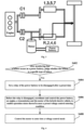
- the hybrid power system of the P2.5 configuration uses a single motor; a power battery is connected to the motor, and an engine is connected to odd axis gears of a transmission (i.e., gears 1, 3, 5, 7 in FIG. 1 ) through a first clutch C1, is connected to the motor through a second clutch C2, and is then connected to even axis gears of the transmission (i.e., gears R, 2, 4, 6 in FIG. 1 ).
- the hybrid power system of the P2.5 configuration has three torque output paths: a Disengaged Path, an ISG path and an EFAD path.
- the Disengaged Path refers to that the motor is disengaged from the engine and the even axis gears of the transmission, in a state as shown in FIG. 1 .
- the ISG path refers to that the motor is communicated with the engine through the second clutch C2, and meanwhile, the motor is disengaged from the even axis gears of the transmission, and then the engine is communicated with the odd axis gears of the transmission through the first clutch C1, as shown in FIG. 2 . In this case, a part of the torque of the engine is output to the motor, and the other part is output to a wheel through the odd axis gears of the transmission.
- the EFAD path refers to that the motor is directly connected to the even axis gears (gears R, 2, 4, 6) of the transmission to boost or charge, and the motor is disengaged from the engine. In this case, the torque of the motor is output to the wheel through the even axis gears of the transmission.
- the research on the control strategy of the hybrid power system of the P2.5 configuration in the case of abnormality of a power battery is less in the industry.
- the existing technology mainly focuses on the limp control strategy after the relay of the power battery is disengaged, but a solution that a vehicle is effectively controlled before a battery relay is disengaged to enable a motor to smoothly enter into voltage control after a battery failure is not available yet.
- the present invention discloses a control method for a hybrid electric vehicle after a battery failure.
- the control method of the present invention is applicable to the hybrid electric vehicle with the hybrid power system of the P2.5 configuration.
- FIG. 4 shows a schematic flow diagram of a control method for a hybrid electric vehicle after a battery failure according to an embodiment of the present invention.
- the control method for the hybrid electric vehicle after the battery failure at least includes the following steps S402 to S408.
- Step S402 after monitoring that a failure occurs in a power battery, whether the failure is a specific type of failure is judged.
- the specific type of failure is a battery failure under which a motor of a hybrid electric vehicle is capable of conducting voltage control. If so, step S404 is performed.
- Step S404 a relay of the power battery is set to be disengaged after a preset time.
- Step S406 before the relay is disengaged, the power battery, an engine, a transmission and the motor of the hybrid electric vehicle are coordinated and controlled, to enable operation states thereof to meet a preset voltage control entering condition.
- Step S408 the motor is controlled to enter into a voltage control mode.
- the control method for the hybrid electric vehicle after the battery failure after monitoring that a failure occurs in a power battery, first judges whether the failure is a specific type of failure under which a motor is capable of conducting voltage control.
- the failure of the power battery is the specific type of failure
- the power battery, an engine, a transmission and a motor of the hybrid electric vehicle are coordinated and controlled, to enable operation states thereof to meet a preset voltage control entering condition, and then the motor is controlled to enter into the voltage control mode.
- the motor can enter into voltage control and operate stably, thus avoiding problems of overtemperature of a battery, serious voltage fluctuation and the like caused by direct voltage control on the motor after a power battery failure.
- the specific type of failure mentioned in the step S402 above can also be referred to as a Voltage of Direct Current (UDC) failure, which has the following characteristics: the UDC failure is a non-serious battery failure, under which the relay of the power battery can be disengaged after a certain time (e.g., a few seconds) after the battery failure is detected, and the motor can enter into a voltage control mode.
- a Battery Management System (BMS) of the hybrid electric vehicle can be used to monitor the failure of the power battery and determine the type thereof.
- a failure signal can also be sent to remind the user.
- power battery failures are first classified in embodiments of the present invention.
- power battery failures is classified into a UDC failure (i.e., the specific type of failure) and a non-UDC failure (i.e., a non-specific type of failure).
- the UDC failure has the features as mentioned above, specifically including slight over-heat of a battery, a mild battery insulation failure, etc.
- the non-UDC failure is generally a serious battery failure, under which the relay of the power battery may be directly disengaged, and the motor cannot conduct voltage control.
- a UDC failure set can be established, and the set may include failure codes, text description, etc. of various UDC failure types. After it is monitored that a failure occurs in the power battery (represented by failure codes, text description, etc.), the monitored failure is matched with the UDC failure set. If the monitored failure is matched with one failure type in the UDC failure set, it is determined that the monitored failure is a UDC failure.
- the relay of the power battery is set to be disengaged after the preset time, and the setting is accomplished by the BMS system.
- the preset time may be set according to actual application demands, for example, set to 5 s.
- a motor In a normal operation state of the hybrid electric vehicle, a motor generally works in a torque control mode. However, after a UDC failure of the power battery occurs, due to the lack of the power battery as an energy buffer, if the motor continues operating in the torque control mode, a bus voltage can easily exceed a threshold value, resulting in an over-voltage failure, so the motor needs to be requested to enter into motor control. However, direct voltage control of the motor can easily lead to problems such as over-temperature of the battery, serious voltage fluctuation, etc.
- step S406 in embodiments of the present invention the power battery, the engine, the transmission and the motor of the hybrid electric vehicle are coordinated and controlled, to enable operation states thereof to meet a preset voltage control entering condition, and then the motor is controlled to enter into voltage control, instead of directly enabling the motor to enter into voltage control.
- the operation states of the power battery, the engine, the transmission and the motor may include a motor mode, a motor torque, a motor rotation speed, an engine state, a charge and discharge power of the power battery, etc.
- the step S406 specifically includes the following multiple steps:
- steps (c) and (d) may be specifically implemented as: first, forbidding requesting the EFAD path (i.e., forbidding connecting the motor with the wheel through the even axis gears of the transmission, requesting to connect the ISG path, i.e., closing the second clutch C2, communicating the motor with the engine, closing the first clutch C1, selecting an appropriate odd axis gear of the transmission, and connecting the engine with the wheel, to enable the engine to meet the driver request torque.
- the motor is allowed to enter into a torque mode, and the torque of the motor is unloaded to approximately 0, such as a value within -7 Nm to 0 Nm, preferably about -5 Nm. Meanwhile, the rotation speed of the motor is adjusted to a preset rotation speed range through a speed adjusting mode.
- the operation state of the motor may further include a rotation speed of a cooling pump (such as a water pump) of the motor.
- the step S406 may further include the following steps: the cooling pump of the motor is controlled to operate at a maximum rotation speed. By controlling the rotation speed of the cooling pump of the motor to the maximum rotation speed, cooling measures for the motor can be ensured, and the temperature of the motor can be controlled, to prevent motor over-heating.
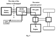
- FIG. 5 shows a schematic diagram of an energy flow direction after a motor enters into a voltage control mode according to an embodiment of the present invention. As shown in FIG.
- the motor enters into the voltage control mode, and after the relay of the power battery is disengaged, the engine drives the motor through the ISG path to generate electric power as a generator, and the electric power generated by the motor is supplied to a low-voltage (such as 12V) electric appliance system of the vehicle through a DCDC converter, so that the hybrid electric vehicle can be continuously used after the power battery failure, and the running distance of the vehicle can be prolonged.
- the DCDC converter may specifically use a Combined Inverter and DC/DC converter (CIDD) module.
- the control method may further include the following step S410: conducting voltage closed loop control on the motor by taking a current voltage of the motor (i.e., a current voltage of a high-voltage end of the motor) as a target voltage, thereby controlling the torque of the motor.
- a current voltage of the motor i.e., a current voltage of a high-voltage end of the motor
- the voltage control can be stable, with small voltage fluctuation.
- the engine may also be controlled to output an expected torque to the motor according to a preset charge power, to drive the motor to generate power to produce electric energy corresponding to the preset charge power.
- the preset charge power may be set according to actual application demands, which is not confined in the present invention.
- a certain charge power is provided for the motor through the engine to drive the motor to generate power, and then the stability of the motor voltage can be further improved.
- control method may further include the following steps S412 and S414.
- Step S412 the relay is disengaged when meeting the preset time.
- Step S414 voltage closed loop control is conducted on the motor by taking a preset voltage target value of the motor as a target voltage till the hybrid electric vehicle stops operating or the failure is repaired.
- the preset voltage target value here may be set according to a rated voltage of the power battery, for example, set at 250 V.
- the state of the relay can be monitored in real time, to judge whether the relay has been disengaged or not. If the relay is still not disengaged, return and continue implementing the step S410, and if the relay has been disengaged, implement the step S414.
- a current voltage of the motor is taken as the target voltage of the motor
- a preset voltage target value of the motor is taken as the target voltage, which may further reduce voltage fluctuation of the motor, thus making the motor operate more stably.
- step S414 voltage control on the motor may also be monitored. Specifically, while the step S414 is being implemented, a difference between the actual voltage of the motor and the preset voltage target value is monitored, and if a lasting time of the difference exceeding a preset voltage threshold exceeds a preset time threshold, the torque of the motor is reduced to 0, and the motor is controlled to exit the voltage control mode.
- Both the preset voltage threshold and the preset time threshold can be set according to actual application demands, for example, the preset voltage threshold can be set as 20 V, and the preset time threshold can be set as 2 s.
- the torque of the motor can gradually decrease (i.e., ramp) with a specific gradient to 0. When the lasting time of the difference exceeding the preset voltage threshold exceeds the preset time threshold, a failure reminding signal can be sent to remind the user.
- the closed loop control in the steps S410 and S414 may be proportion integration differentiation (PID) control.
- PID proportion integration differentiation
- the control method may further include the following step S416: by taking a difference between the driver request torque and an actual torque of the motor as an engine request torque, controlling the engine to operate according to the engine request torque to output a torque to the transmission and the motor, to enable the output torque of the engine to meet a wheel driving demand and a low-voltage system charge demand of the hybrid electric vehicle. After the motor enters into the voltage control mode, the motor generates power under the driving of the engine.
- the actual torque of the motor is a negative value
- the driver request torque may be a negative value or a positive value according to different running states of a vehicle, for example, when the vehicle slides, the driver request torque is a negative value, and when the vehicle advances normally, the driver request torque is a positive value. Therefore, by taking the difference between the driver request torque and the actual torque of the motor as an engine request torque, the actual torque of the motor can be used as an additional request compensation torque of the engine in addition to the driver request torque. By compensating the output torque of the engine according to the actual torque of the motor, after the failure occurs in the power battery, the engine is still capable of meeting the driver request and the low-voltage system power supply of the vehicle, so that the hybrid electric vehicle is still capable of keeping operating.
- the hybrid electric vehicle is still capable of operating like a conventional vehicle, the motor is capable of smoothly entering into the voltage control mode and operates stably, and while a driver is reminded of battery abnormality, the voltage control mode can also be an assistant driving mode to enable the vehicle to continue operating, thereby improving the security and the robustness of the vehicle.
- the present invention further provides a control system for a hybrid electric vehicle after a battery failure.
- the control system is also applicable to the hybrid electric vehicle with the hybrid power system of the P2.5 configuration.
- FIG. 7 shows a structural schematic diagram of a control system for a hybrid electric vehicle after a battery failure according to an embodiment of the present invention.
- the control system at least includes: a vehicle control unit 1, a motor control unit 2, a transmission control unit 3, an engine control unit 4 and a battery control unit 5.
- the battery control unit 5 (which may be a BMS) is connected to a power battery, and configured to, after monitoring that a failure occurs in the power battery, judge whether the failure is a specific type of failure or not, wherein the specific type of failure is a battery failure under which a motor of the hybrid electric vehicle is capable of conducting voltage control. If the failure is the specific type of failure, the battery control unit 5 sets that a relay of the power battery is disengaged after a preset time. The preset time may be set by the battery control unit 5 and the vehicle control unit 1 according to actual application demands, for example, set to 5 s.
- the motor control unit 2 may be a Microcontroller unit (MCU), which is connected to the motor.
- the Transmission Control Unit 3 (TCU) is connected to a transmission.
- the engine control unit 4 may be an Electronic Control Unit (ECU), which is connected to an engine.
- the Vehicle Control Unit 1 (VCU) is connected to the motor control unit 2, the transmission control unit 3, the engine control unit 4 and the battery control unit 5, respectively.
- the vehicle control unit 1, the motor control unit 2, the transmission control unit 3, the engine control unit 4 and the battery control unit 5 are configured to: before the relay is disengaged, coordinate and control the power battery, the engine, the transmission and the motor of the hybrid electric vehicle, to enable operation states thereof to meet a preset voltage control entering condition.
- the motor control unit 2 is further configured to, after the operation states of the power battery, the engine, the transmission and the motor of the hybrid electric vehicle meet the preset voltage control entering condition, control the motor to enter into a voltage control mode.
- the battery control unit 5 is further configured to: if the failure is the specific type of failure, confine a charge and discharge peak power of the power battery to a preset power limit, and send a failure signal to the vehicle control unit 1.
- the vehicle control unit 1 is further configured to: generate a corresponding control signal according to the failure signal and send the control signal to the motor control unit 2, the transmission control unit 3 and the engine control unit 4.
- the engine control unit 4 is further configured to: control the engine to be in a start state according to the control signal of the vehicle control unit 1.
- the transmission control unit 3 is further configured to: according to the control signal of the vehicle control unit 1 and a driver request torque, select a gear of the transmission with a required transmission ratio to be connected to the engine.
- the motor control unit 2 is further configured to: control the motor to be communicated with the engine according to the control signal of the vehicle control unit 1, control the torque of the motor to a preset torque range smaller than 0 and approximate to 0, and adjust the rotation speed of the motor to a preset rotation speed range.
- the vehicle control unit 1 sends an engine start request to the engine control unit 4, and the engine control unit 4 controls the engine to be in the start state according to the engine start request.
- the vehicle control unit 1 forbids requesting an EFAD path of the motor and requests an ISG path of the motor, and then the vehicle control unit 1 sends a torque control mode request and a torque control instruction to the motor control unit 2; the motor control unit 2 controls the motor to be communicated with the engine, and controls the torque of the motor to be in the preset torque range smaller than 0 and approximate to 0.
- the vehicle control unit 1 further sends a rotation speed control instruction to the motor control unit 2, and the motor control unit 2 confines the rotation speed of the motor within the preset rotation speed range according to the rotation speed control instruction.
- the vehicle control unit 1 sends an odd axis gear request to the transmission control unit 3, and the transmission control unit 3 selects an odd axis gear of the transmission with a required transmission ratio to be connected to the engine according to the odd axis gear request and the driver request torque.
- control system may further include a cooling pump control unit (not shown in FIG. 7 ).
- the cooling pump control unit is connected to the vehicle control unit 1.
- the vehicle control unit 1 is further configured to: generate a corresponding control signal according to the failure signal and send the control signal to the cooling pump control unit.
- the cooling pump control unit is further configured to: control a cooling pump of the motor to operate at a maximum rotation speed according to the control signal (specifically a cooling pump rotation speed control instruction) of the vehicle control unit 1.
- the motor control unit 2 is further configured to: after controlling the motor to enter into the voltage control mode, and before the relay is disengaged, conduct voltage closed loop control on the motor by taking a current voltage of the motor as a target voltage.
- the motor control unit 2 is further configured to: in the process of conducting voltage closed loop control on the motor by taking the current voltage of the motor as the target voltage, send a power generation request to the vehicle control unit 1 according to a preset charge power.
- the vehicle control unit 1 is further configured to: generate an engine torque distribution signal according to the power generation request and send the engine torque distribution signal to the engine control unit 4.
- the engine control unit 4 is further configured to: control the engine to output a required torque to the motor according to the engine torque distribution signal, to drive the motor to generate power to produce electric energy corresponding to the preset charge power.
- the battery control unit 5 is further configured to: after the motor control unit 2 conducts voltage closed loop control on the motor by taking the current voltage of the motor as the target voltage, disengage the relay when meeting the preset time.
- the motor control unit 2 is further configured to: after the relay is disengaged by the battery control unit 5, conduct voltage closed loop control on the motor by taking a preset voltage target value of the motor as the target voltage till the hybrid electric vehicle stops operating or the failure is repaired.
- the motor control unit 2 is further configured to: in the process of conducting voltage closed loop control on the motor by taking the preset voltage target value of the motor as the target voltage, monitor a difference between an actual voltage of the motor and the preset voltage target value; and if the lasting time of the difference exceeding a preset voltage threshold exceeds a preset time threshold, reduce the torque of the motor to 0, and control the motor to exit the voltage control mode.
- the engine control unit 4 is further configured to: after the motor control unit 2 controls the motor to enter into the voltage control mode, by taking a difference between the driver request torque and an actual torque of the motor as an engine request torque, control the engine to operate according to the engine request torque to output a torque to the transmission and the motor, to enable the output torque of the engine to meet a wheel driving demand and a low-voltage system charge demand of the hybrid electric vehicle.
- FIG. 8 shows a schematic diagram of change of operation states of components in the process from a battery failure occurring to conducting motor voltage control according to an embodiment of the present invention, and the horizontal axis in FIG. 8 represents time (in an unit of s).
- This embodiment is specifically a field test embodiment, and an initial vehicle test condition is that the vehicle runs in a pure electric mode.
- a UDC failure happens to a battery, and a failure signal is sent to the VCU.
- the VCU receives the failure signal, and an engine start request is sent to the ECU, the engine is started through a clutch, and in the start process, a clutch start loss torque is compensated by a motor torque.
- the engine is successfully started. Since the motor is connected to the even axis of the transmission, an EFAD torque output path of the motor is forbidden, and at 81.7 s, the VCU sends a motor rotation speed control mode request and a motor rotation speed request to the MCU.
- the MCU receives a request signal, changes the motor mode into a rotation speed mode, and starts to synchronize the motor rotation speed with a target rotation speed.
- the motor path is changed into the ISG path.
- the VCU sends a torque control mode request to the MCU to request controlling the motor torque to approximately -5 Nm.
- the VCU sends a voltage control mode request to the MCU.
- the MCU controls the motor to enter into voltage control, and in the voltage control, the MCU takes a current motor voltage as the target voltage, to keep the motor voltage at a current level.
- the relay of the battery is disengaged, and the voltage drop during disengagement of the relay is within a safe range.
- a high-voltage bus is separately controlled by the MCU, and is supplied with power by a single chip microcomputer, and the voltage is kept at approximately 250 V.
- the motor rotation speed changes within 1000-3500 rpm through an accelerator, and loads of 12 V are changed by turning on and turning off an air conditioner, lights, windshield wipers, etc.
- loads of 12 V are changed by turning on and turning off an air conditioner, lights, windshield wipers, etc.
- the test results of the whole vehicle show that after the failure occurs in the power battery, the motor voltage is in a good safe range before the motor enters into the voltage control mode, and the 12 V voltage is stable after the motor enters into the voltage control mode, so that the whole vehicle can operate stably.
- the present invention further provides a hybrid electric vehicle, which includes the control system for a hybrid electric vehicle after a battery failure of the forgoing any embodiment or a combination thereof.
- the embodiments of the present invention can achieve the following beneficial effects:
- the control method and system for the hybrid electric vehicle after the battery failure provided by embodiments of the present invention, after monitoring that a failure occurs in a power battery, first judge whether the failure is a specific type of failure under which a motor is capable of conducting voltage control.
- the failure of the power battery is the specific type of failure, before the relay of the power battery is disengaged, the power battery, an engine, a transmission and a motor of the hybrid electric vehicle are coordinated and controlled, to enable operation states thereof to meet a preset voltage control entering condition, and then the motor is controlled to enter into the voltage control mode.
- the motor can enter into voltage control and operate stably, thus avoiding problems of overtemperature of a battery, serious voltage fluctuation and the like caused by direct voltage control on the motor after a power battery failure.
- the difference between the driver request torque and the actual torque of the motor is taken as the engine request torque, to enable the output torque of the engine to meet the wheel driving demand and the low-voltage system charge demand of the hybrid electric vehicle, and thus after the failure occurs in the power battery, the engine is still capable of meeting the driver request and the low-voltage system charge request of the vehicle, so that the hybrid electric vehicle is still capable of continuously operating like a conventional vehicle, and the security and robustness of the vehicle are improved.
Landscapes
- Engineering & Computer Science (AREA)
- Mechanical Engineering (AREA)
- Transportation (AREA)
- Combustion & Propulsion (AREA)
- Chemical & Material Sciences (AREA)
- Power Engineering (AREA)
- Sustainable Development (AREA)
- Sustainable Energy (AREA)
- Life Sciences & Earth Sciences (AREA)
- Health & Medical Sciences (AREA)
- Biomedical Technology (AREA)
- General Health & Medical Sciences (AREA)
- Automation & Control Theory (AREA)
- Electric Propulsion And Braking For Vehicles (AREA)
- Hybrid Electric Vehicles (AREA)
Claims (13)
- Steuerverfahren für ein Hybrid-Elektrofahrzeug nach einem Batterieausfall, wobei das Hybrid-Elektrofahrzeug einen Elektromotor, der auch in der Lage ist, als Generator verwendet zu werden, ein Getriebe (R, 2, 4, 6; 1, 3, 5, 7), einen Verbrennungsmotor, eine Leistungsbatterie und mindestens eine Kupplung (C1, C2) umfasst, wobei
der Verbrennungsmotor über die mindestens eine Kupplung mit dem Getriebe verbunden ist, der Verbrennungsmotor über die mindestens eine Kupplung mit dem Elektromotor verbunden ist, die Leistungsbatterie über ein Relais mit dem Elektromotor verbunden ist und die Leistungsbatterie über das Relais mit einem Elektrogeräte-Niederspannungssystem des Fahrzeugs verbunden ist; und das Steuerverfahren umfasst:nach dem Beobachten, dass ein Ausfall in der Leistungsbatterie auftritt, Beurteilen, ob der Ausfall ein spezifischer Ausfalltyp ist oder nicht, wobei der spezifische Ausfalltyp ein Batterieausfall ist, bei dem das Relais der Leistungsbatterie eine bestimmte Zeit nach dem Erkennen des Batterieausfalls geöffnet werden kann und der Elektromotor des Hybrid-Elektrofahrzeugs in der Lage ist, als Generator verwendet zu werden;falls das Beurteilungsergebnis ja ist, Einstellen des Relais der Leistungsbatterie, sodass es nach einer voreingestellten Zeit geöffnet wird;bevor das Relais geöffnet wird, Koordinieren und Steuern der Leistungsbatterie, des Verbrennungsmotors, des Getriebes und des Elektromotors des Hybrid-Elektrofahrzeugs, sodass Betriebszuständen davon ermöglicht wird, eine voreingestellte Spannungssteuerungsmodus-Einschaltbedingung zu erfüllen, durch:Steuern des Verbrennungsmotors, sodass er sich in einen Startzustand befindet, wobei der Verbrennungsmotor bei fahrendem Fahrzeug durch die mindestens eine Kupplung gestartet wird;Auswählen, gemäß einem vom Fahrer angeforderten Drehmoment, eines Gangs des Getriebes mit einem für die Verbindung mit dem Verbrennungsmotor erwarteten Übersetzungsverhältnis; undSteuern eines Drehmoments des Elektromotors auf einen voreingestellten Drehmomentbereich kleiner als 0 und ungefähr 0 und Anpassen einer Drehgeschwindigkeit des Elektromotors auf einen voreingestellten Drehgeschwindigkeitsbereich; undSteuern des Elektromotors, sodass er in einen Spannungssteuerungsmodus eintritt nachdem das Relais der Leistungsbatterie eingestellt wird, sodass es nach der voreingestellten Zeit geöffnet wird, der Elektromotor über die mindestens eine Kupplung mit dem Verbrennungsmotor verbunden wird, um elektrische Leistung als Generator zu erzeugen, und die vom Elektromotor erzeugte elektrische Leistung dem Elektrogeräte-Niederspannungssystem des Fahrzeugs zugeführt wird. - Steuerverfahren nach Anspruch 1, wobei das Koordinieren und Steuern der Leistungsbatterie, des Verbrennungsmotors, des Getriebes und des Elektromotors des Hybrid-Elektrofahrzeugs, um den Betriebszuständen davon zu ermöglichen, die voreingestellte Spannungssteuerungs-Einschaltbedingung zu erfüllen, ferner implementiert ist durch:
Steuern einer Kühlpumpe des Elektromotors, sodass sie bei einer maximalen Drehgeschwindigkeit betrieben wird. - Steuerverfahren nach Anspruch 1, wobei das Steuerverfahren nach dem Steuern des Elektromotors, sodass er in den Spannungssteuerungsmodus eintritt, und bevor das Relais geöffnet wird, ferner umfasst:
Regeln einer Spannung am Elektromotor unter Verwendung einer aktuellen Spannung des Elektromotors als Zielspannung, wobei das Steuerverfahren bei dem Regeln der Spannung am Elektromotor unter Verwendung der aktuellen Spannung des Elektromotors als Zielspannung ferner umfasst:
gemäß einer voreingestellten Aufladeleistung, Steuern des Verbrennungsmotors, sodass er ein erwartetes Drehmoment an den Elektromotor ausgibt, um den Elektromotor zur Leistungserzeugung anzutreiben, um elektrische Energie entsprechend der voreingestellten Aufladeleistung zu erzeugen. - Steuerverfahren nach Anspruch 3, wobei das Steuerverfahren nach dem Regeln der Spannung am Elektromotor unter Verwendung der aktuellen Spannung des Elektromotors als Zielspannung ferner umfasst:Öffnen des Relais, wenn die voreingestellte Zeit erreicht ist; undRegeln einer Spannung am Elektromotor unter Verwendung eines voreingestellten Spannungszielwerts des Elektromotors als Zielspannung, bis das Hybrid-Elektrofahrzeug den Betrieb einstellt oder der Ausfall repariert ist.
- Steuerverfahren nach Anspruch 4, wobei das Steuerverfahren bei dem Regeln der Spannung am Elektromotor unter Verwendung des voreingestellten Spannungszielwerts des Elektromotors als Zielspannung ferner umfasst:Beobachten eines Unterschieds zwischen einer tatsächlichen Spannung und dem voreingestellten Spannungszielwert des Elektromotors; und,wenn die Zeitdauer, während der der Unterschied einen voreingestellten Spannungsschwellenwert überschreitet, einen voreingestellten Zeitdauer-Schwellenwert überschreitet, Reduzieren eines Drehmoments des Elektromotors auf 0 und Steuern des Elektromotors, sodass er den Spannungssteuerungsmodus verlässt.
- Steuerverfahren nach einem der Ansprüche 3 bis 5, wobei das Regeln eine Proportional-integral-derivativ-Regelung (PID-Regelung) ist.
- Steuerverfahren nach Anspruch 1, wobei das Steuerverfahren nach dem Steuern des Elektromotors, sodass er in den Spannungssteuerungsmodus eintritt, ferner umfasst:
unter Verwendung eines Unterschieds zwischen dem vom Fahrer angeforderten Drehmoment und dem tatsächlichen Drehmoment des Elektromotors als angefordertes Verbrennungsmotordrehmoment, Steuern des Verbrennungsmotors, sodass er gemäß dem angeforderten Verbrennungsmotordrehmoment betrieben wird, um ein Drehmoment an das Getriebe und den Elektromotor auszugeben, damit das Ausgangsdrehmoment des Verbrennungsmotors einen Antriebsbedarf der Räder und einen Aufladebedarf des Niederspannungssystems des Hybrid-Elektrofahrzeugs befriedigt. - Steuerungssystem für ein Hybrid-Elektrofahrzeug nach einem Batterieausfall, umfassend:eine Fahrzeugsteuereinheit (1), eine Elektromotorsteuereinheit (2), eine Getriebesteuereinheit (3), eine Verbrennungsmotorsteuereinheit (4) und eine Batteriesteuereinheit (5),einen Elektromotor, der auch in der Lage ist, als Generator verwendet zu werden, ein Getriebe (R, 2, 4, 6; 1, 3, 5, 7), einen Verbrennungsmotor, eine Leistungsbatterie und mindestens eine Kupplung (C1, C2), wobei der Verbrennungsmotor über die mindestens eine Kupplung mit dem Getriebe verbunden ist, der Verbrennungsmotor über die mindestens eine Kupplung mit dem Elektromotor verbunden ist, die Leistungsbatterie über ein Relais mit dem Elektromotor verbunden ist und die Leistungsbatterie über das Relais mit einem Elektrogeräte-Niederspannungssystem des Fahrzeugs verbunden ist,wobei die Batteriesteuereinheit (5) dazu eingerichtet ist:nach einem Beobachten, dass ein Ausfall in der Leistungsbatterie auftritt, zu beurteilen, ob der Ausfall ein spezifischer Ausfalltyp ist oder nicht, wobei der spezifische Ausfalltyp ein Batterieausfall ist, bei dem das Relais der Leistungsbatterie eine bestimmte Zeit nach dem Erkennen des Batterieausfalls geöffnet werden kann und der Elektromotor des Hybrid-Elektrofahrzeugs als Generator verwendet werden kann; und,falls das Beurteilungsergebnis ja ist, das Relais der Leistungsbatterie so einzustellen, dass es nach einer voreingestellten Zeit geöffnet wird;wobei die Fahrzeugsteuereinheit (1), die Elektromotorsteuereinheit (2), die Getriebesteuereinheit (3), die Verbrennungsmotorsteuereinheit (4) und die Batteriesteuereinheit (5) dazu eingerichtet sind:
bevor das Relais geöffnet wird, die Leistungsbatterie, den Verbrennungsmotor, das Getriebe und den Elektromotor des Hybrid-Elektrofahrzeugs zu koordinieren und zu steuern, sodass Betriebszuständen davon ermöglicht wird, eine voreingestellte Spannungssteuerungsmodus-Einschaltbedingung zu erfüllen, durch:Beschränken einer Spitzenleistung bei Aufladung und Entladung der Leistungsbatterie auf eine voreingestellte Leistungsgrenze;Steuern des Verbrennungsmotors, sodass er sich in einem Startzustand befindet, wobei der Verbrennungsmotor bei fahrendem Fahrzeug durch die mindestens eine Kupplung gestartet wird;Auswählen, gemäß einem vom Fahrer angeforderten Drehmoment, eines Gangs des Getriebes mit einem für die Verbindung mit dem Verbrennungsmotor erwarteten Übersetzungsverhältnis; undSteuern eines Drehmoments des Elektromotors auf einen voreingestellten Drehmomentbereich kleiner als 0 und ungefähr 0 und Anpassen einer Drehgeschwindigkeit des Elektromotors auf einen voreingestellten Drehgeschwindigkeitsbereich;Steuern des Elektromotors, sodass er in einen Spannungssteuerungsmodus eintritt nachdem das Relais der Leistungsbatterie eingestellt wird, sodass es nach der voreingestellten Zeit geöffnet wird, der Elektromotor über die mindestens eine Kupplung mit dem Verbrennungsmotor verbunden wird, um elektrische Leistung als Generator zu erzeugen, und die vom Elektromotor erzeugte elektrische Leistung dem Elektrogeräte-Niederspannungssystem des Fahrzeugs zugeführt wird. - Steuerungssystem nach Anspruch 8, wobei das Steuerungssystem ferner eine Kühlpumpe-Steuereinheit umfasst;die Fahrzeugsteuereinheit (1) ferner dazu eingerichtet ist: gemäß dem Ausfall-Signal ein entsprechendes Steuersignal zu erzeugen und das Steuersignal an die Kühlpumpe-Steuereinheit zu senden; unddie Kühlpumpe-Steuereinheit dazu eingerichtet ist: gemäß dem Steuersignal der Fahrzeugsteuereinheit eine Kühlpumpe des Elektromotors mit maximaler Drehgeschwindigkeit zu betreiben.
- Steuerungssystem nach Anspruch 8, wobei die Elektromotorsteuereinheit (2) ferner dazu eingerichtet ist:
nach dem Steuern des Elektromotors, sodass er in den Spannungssteuerungsmodus eintritt, und bevor das Relais geöffnet wird, eine Spannung am Elektromotor unter Verwendung der aktuellen Spannung des Elektromotors als Zielspannung zu regeln, wobei die Elektromotorsteuereinheit (2) ferner dazu eingerichtet ist:bei dem Regeln der Spannung am Elektromotor unter Verwendung der aktuellen Spannung des Elektromotors als Zielspannung gemäß einer voreingestellten Aufladeleistung eine Anforderung zur Leistungserzeugung an die Fahrzeugsteuereinheit (1) zu senden;wobei die Fahrzeugsteuereinheit (1) ferner dazu eingerichtet ist: gemäß der Anforderung zur Leistungserzeugung ein Signal zur Verteilung des Verbrennungsmotordrehmoments zu erzeugen und das Signal zur Verteilung des Verbrennungsmotordrehmoments an die Verbrennungsmotorsteuereinheit (4) zu senden; unddie Verbrennungsmotorsteuereinheit (4) ferner dazu eingerichtet ist: gemäß dem Signal zur Verteilung des Verbrennungsmotordrehmoments den Verbrennungsmotor zu steuern, sodass er ein erforderliches Drehmoment an den Elektromotor ausgibt, um den Elektromotor zur Leistungserzeugung anzutreiben, um elektrische Energie entsprechend der voreingestellten Aufladeleistung zu erzeugen. - Steuerungssystem nach Anspruch 10, wobei die Batteriesteuereinheit (5) ferner dazu eingerichtet ist: nachdem die Elektromotorsteuereinheit (2) die Spannung am Elektromotor unter Verwendung der aktuellen Spannung des Elektromotors als Zielspannung regelt und wenn die voreingestellte Zeit erreicht ist, das Relais zu öffnen; und
die Elektromotorsteuereinheit (2) ferner dazu eingerichtet ist: nach dem Öffnen des Relais durch die Batteriesteuereinheit (5) eine Spannung am Elektromotor unter Verwendung eines voreingestellten Spannungszielwerts des Elektromotors als Zielspannung zu regeln, bis das Hybrid-Elektrofahrzeug den Betrieb einstellt oder der Ausfall repariert ist, wobei die Elektromotorsteuereinheit (2) ferner dazu eingerichtet ist:bei dem Regeln der Spannung am Elektromotor unter Verwendung des voreingestellten Spannungszielwerts des Elektromotors als Zielspannung einen Unterschied zwischen einer tatsächlichen Spannung des Elektromotors und dem voreingestellten Spannungszielwert zu beobachten; und,wenn die Zeitdauer, während der der Unterschied einen voreingestellten Spannungsschwellenwert überschreitet, einen voreingestellten Zeitdauer-Schwellenwert überschreitet, das Drehmoment des Elektromotors auf 0 zu reduzieren und den Elektromotor so zu steuern, dass er den Spannungssteuerungsmodus verlässt. - Steuerungssystem nach Anspruch 8, wobei die Verbrennungsmotorsteuereinheit (4) ferner dazu eingerichtet ist:
nachdem die Elektromotorsteuereinheit (2) den Elektromotor so steuert, dass er in den Spannungssteuerungsmodus eintritt, unter Verwendung eines Unterschieds zwischen dem vom Fahrer angeforderten Drehmoment und dem tatsächlichen Drehmoment des Elektromotors als angefordertes Verbrennungsmotordrehmoment, den Verbrennungsmotor so zu steuern, dass er entsprechend dem angeforderten Verbrennungsmotordrehmoment betrieben wird, um ein Drehmoment an das Getriebe und den Elektromotor auszugeben, damit das Ausgangsdrehmoment des Verbrennungsmotors einen Antriebsbedarf der Räder und einen Aufladebedarf des Niederspannungssystems des Hybrid-Elektrofahrzeugs befriedigt. - Hybrid-Elektrofahrzeug mit dem Steuerungssystem für ein Hybrid-Elektrofahrzeug nach einem Batterieausfall nach einem der Ansprüche 8 bis 12.
Applications Claiming Priority (1)
| Application Number | Priority Date | Filing Date | Title |
|---|---|---|---|
| PCT/CN2020/126433 WO2022094786A1 (zh) | 2020-11-04 | 2020-11-04 | 一种混合动力车辆及其电池故障后的控制方法和系统 |
Publications (3)
| Publication Number | Publication Date |
|---|---|
| EP4032737A1 EP4032737A1 (de) | 2022-07-27 |
| EP4032737A4 EP4032737A4 (de) | 2022-11-30 |
| EP4032737B1 true EP4032737B1 (de) | 2023-10-04 |
Family
ID=80824503
Family Applications (1)
| Application Number | Title | Priority Date | Filing Date |
|---|---|---|---|
| EP20955472.4A Active EP4032737B1 (de) | 2020-11-04 | 2020-11-04 | Hybridfahrzeug und steuerungsverfahren und -system nach ausfall der hybridfahrzeugbatterie |
Country Status (3)
| Country | Link |
|---|---|
| EP (1) | EP4032737B1 (de) |
| CN (1) | CN114269617B (de) |
| WO (1) | WO2022094786A1 (de) |
Cited By (1)
| Publication number | Priority date | Publication date | Assignee | Title |
|---|---|---|---|---|
| US20250065863A1 (en) * | 2021-12-23 | 2025-02-27 | Cummins Inc. | Control system for hybrid electric vehicle |
Families Citing this family (13)
| Publication number | Priority date | Publication date | Assignee | Title |
|---|---|---|---|---|
| CN114889583A (zh) * | 2022-05-17 | 2022-08-12 | 岚图汽车科技有限公司 | 一种混合动力汽车的驱动电机控制方法及装置 |
| CN117341669A (zh) * | 2022-06-28 | 2024-01-05 | 长城汽车股份有限公司 | 车辆及其混动系统的控制方法与装置、存储介质 |
| CN115195698B (zh) * | 2022-06-29 | 2025-04-01 | 中国第一汽车股份有限公司 | 一种发动机启动方法 |
| CN115416489B (zh) * | 2022-08-22 | 2025-07-01 | 东风汽车集团股份有限公司 | 一种故障处理方法、装置及新能源汽车 |
| CN115327465A (zh) * | 2022-08-29 | 2022-11-11 | 广汽埃安新能源汽车有限公司 | 三电测试系统的监控方法及装置 |
| CN115402106B (zh) * | 2022-08-30 | 2023-09-26 | 小米汽车科技有限公司 | 用于车辆的电压控制方法、装置、车辆及存储介质 |
| CN115571109B (zh) * | 2022-10-24 | 2026-04-14 | 深蓝汽车科技有限公司 | 混合动力升压控制系统、方法及车辆 |
| CN115923519B (zh) * | 2023-01-02 | 2025-05-09 | 重庆长安汽车股份有限公司 | 混动车升降压模块过流保护方法、系统、车辆及存储介质 |
| CN115923771B (zh) * | 2023-01-02 | 2025-07-22 | 重庆长安汽车股份有限公司 | 混动车辆行驶中电池故障下的发动机起动控制方法及车辆 |
| CN117698509B (zh) * | 2024-02-02 | 2024-07-12 | 宁德时代新能源科技股份有限公司 | 控制电池的方法和装置 |
| CN119821355B (zh) * | 2025-02-24 | 2025-11-21 | 长城汽车股份有限公司 | 车辆的控制方法、装置、车辆及存储介质 |
| CN119773728A (zh) * | 2025-03-11 | 2025-04-08 | 宁德时代新能源科技股份有限公司 | 车辆控制方法、车辆控制装置、多动力车辆及存储介质 |
| CN119928820A (zh) * | 2025-03-21 | 2025-05-06 | 长城汽车股份有限公司 | 车辆控制方法、装置、车辆和计算机可读存储介质 |
Family Cites Families (16)
| Publication number | Priority date | Publication date | Assignee | Title |
|---|---|---|---|---|
| KR100921061B1 (ko) * | 2008-03-27 | 2009-10-08 | 현대자동차주식회사 | 하이브리드 차량의 배터리 보호방법 |
| KR101144033B1 (ko) * | 2009-12-04 | 2012-05-23 | 현대자동차주식회사 | 하이브리드 차량의 모터 구동 시스템 제어 방법 |
| JP2013133041A (ja) * | 2011-12-27 | 2013-07-08 | Toyota Motor Corp | ハイブリッド車両およびハイブリッド車両の制御方法 |
| US9481354B2 (en) * | 2014-05-08 | 2016-11-01 | Hyundai Motor Company | Emergency operation method of hybrid vehicle |
| KR101684099B1 (ko) * | 2015-04-15 | 2016-12-20 | 현대자동차주식회사 | 친환경 차량의 고장 처리 장치 및 방법 |
| KR102383451B1 (ko) * | 2016-12-16 | 2022-04-06 | 현대자동차주식회사 | 차량 발전 제어 장치 및 방법 |
| CN107487321B (zh) * | 2017-06-19 | 2020-01-17 | 宝沃汽车(中国)有限公司 | 混合动力汽车的离合器控制方法及装置 |
| CN108528440B (zh) * | 2018-03-27 | 2020-05-19 | 吉利汽车研究院(宁波)有限公司 | 一种用于混合动力车辆的高压供电控制方法 |
| CN108859766B (zh) * | 2018-06-04 | 2021-03-16 | 武汉理工大学 | 四轮轮毂电机混合动力汽车故障协调控制方法 |
| CN108819937B (zh) * | 2018-07-04 | 2020-04-07 | 重庆长安汽车股份有限公司 | 新能源汽车跛行模式控制方法及系统 |
| CN111619350A (zh) * | 2019-02-27 | 2020-09-04 | 北京宝沃汽车有限公司 | 整车控制方法、整车控制系统和一种车辆 |
| CN110606074B (zh) * | 2019-09-26 | 2020-09-22 | 中国第一汽车股份有限公司 | 一种48v混合动力车辆的跛行控制方法 |
| CN110782633A (zh) * | 2019-10-31 | 2020-02-11 | 重庆长安新能源汽车科技有限公司 | 一种新能源汽车动力电池热失控报警系统及方法 |
| CN110877607B (zh) * | 2019-11-26 | 2021-04-06 | 重庆长安汽车股份有限公司 | 一种混合动力汽车自发电跛行系统及方法 |
| CN111546894A (zh) * | 2020-05-21 | 2020-08-18 | 新石器慧通(北京)科技有限公司 | 一种车辆异常下电控制方法、系统及车辆 |
| CN111717029B (zh) * | 2020-06-08 | 2022-03-22 | 北京汽车股份有限公司 | 跛行模式低压负载供电控制方法、系统及混合动力汽车 |
-
2020
- 2020-11-04 EP EP20955472.4A patent/EP4032737B1/de active Active
- 2020-11-04 WO PCT/CN2020/126433 patent/WO2022094786A1/zh not_active Ceased
- 2020-11-04 CN CN202080051345.3A patent/CN114269617B/zh active Active
Cited By (1)
| Publication number | Priority date | Publication date | Assignee | Title |
|---|---|---|---|---|
| US20250065863A1 (en) * | 2021-12-23 | 2025-02-27 | Cummins Inc. | Control system for hybrid electric vehicle |
Also Published As
| Publication number | Publication date |
|---|---|
| EP4032737A1 (de) | 2022-07-27 |
| EP4032737A4 (de) | 2022-11-30 |
| CN114269617A (zh) | 2022-04-01 |
| WO2022094786A1 (zh) | 2022-05-12 |
| CN114269617B (zh) | 2023-12-05 |
Similar Documents
| Publication | Publication Date | Title |
|---|---|---|
| EP4032737B1 (de) | Hybridfahrzeug und steuerungsverfahren und -system nach ausfall der hybridfahrzeugbatterie | |
| US11351975B2 (en) | Hybrid-electric vehicle plug-out mode energy management | |
| CN102616148B (zh) | 一种增程式电动汽车控制系统及其控制方法 | |
| EP2404801B1 (de) | Ladungs-/entladungssteuersystem für ein hybridfahrzeug und steuerverfahren dafür | |
| US10160307B2 (en) | System and method for controlling motor temperature for green car | |
| US9296289B2 (en) | Hybrid vehicle and control method of hybrid vehicle | |
| JP2004048987A (ja) | ハイブリッド電気自動車の制御方法 | |
| US12017507B2 (en) | Blower motor operation for an electrified vehicle | |
| US20160212885A1 (en) | Hybrid vehicle | |
| US11413932B2 (en) | Blower motor operation | |
| WO2022217388A1 (zh) | 双电机混合动力车辆及其电池故障处理方法和系统 | |
| KR101765643B1 (ko) | 하이브리드 차량의 정속 주행을 위한 배터리의 soc 제어 방법 및 그 제어 장치 | |
| EP4159518B1 (de) | Gleichstromausgangsspannungssteuerverfahren und -steuersystem für hybridfahrzeug | |
| JP2009160978A (ja) | 内燃機関制御装置 | |
| KR101198808B1 (ko) | 하이브리드 차량에서의 엔진 아이들 제어 방법 | |
| US20240067160A1 (en) | Redundant low voltage battery charging control system for a vehicle | |
| US12110006B2 (en) | System and method for controlling limp-home reverse traveling of hybrid electric vehicle | |
| US20250065863A1 (en) | Control system for hybrid electric vehicle | |
| CN120497532B (zh) | 一种电动化上装电池加热系统及加热方法 | |
| Jing et al. | Research on voltage control of P2. 5 hybrid system | |
| JP7651995B2 (ja) | 排気還流システムの故障診断装置 | |
| Tashiro | Power Management of a Hybrid Electric Vehicle During Warm-up Period Considering Energy Consumption of Cabin Heat Components | |
| WO2025085464A1 (en) | Hybrid vehicle energy balance control system for co2 reduction |
Legal Events
| Date | Code | Title | Description |
|---|---|---|---|
| STAA | Information on the status of an ep patent application or granted ep patent |
Free format text: STATUS: UNKNOWN |
|
| STAA | Information on the status of an ep patent application or granted ep patent |
Free format text: STATUS: THE INTERNATIONAL PUBLICATION HAS BEEN MADE |
|
| PUAI | Public reference made under article 153(3) epc to a published international application that has entered the european phase |
Free format text: ORIGINAL CODE: 0009012 |
|
| STAA | Information on the status of an ep patent application or granted ep patent |
Free format text: STATUS: REQUEST FOR EXAMINATION WAS MADE |
|
| 17P | Request for examination filed |
Effective date: 20220407 |
|
| AK | Designated contracting states |
Kind code of ref document: A1 Designated state(s): AL AT BE BG CH CY CZ DE DK EE ES FI FR GB GR HR HU IE IS IT LI LT LU LV MC MK MT NL NO PL PT RO RS SE SI SK SM TR |
|
| STAA | Information on the status of an ep patent application or granted ep patent |
Free format text: STATUS: EXAMINATION IS IN PROGRESS |
|
| A4 | Supplementary search report drawn up and despatched |
Effective date: 20221102 |
|
| RIC1 | Information provided on ipc code assigned before grant |
Ipc: B60L 50/61 20190101ALI20221026BHEP Ipc: B60L 50/16 20190101ALI20221026BHEP Ipc: B60L 15/20 20060101ALI20221026BHEP Ipc: B60L 3/00 20190101AFI20221026BHEP |
|
| 17Q | First examination report despatched |
Effective date: 20221114 |
|
| RIC1 | Information provided on ipc code assigned before grant |
Ipc: B60L 50/61 20190101ALI20230220BHEP Ipc: B60L 50/16 20190101ALI20230220BHEP Ipc: B60L 15/20 20060101ALI20230220BHEP Ipc: B60L 3/00 20060101AFI20230220BHEP |
|
| GRAP | Despatch of communication of intention to grant a patent |
Free format text: ORIGINAL CODE: EPIDOSNIGR1 |
|
| STAA | Information on the status of an ep patent application or granted ep patent |
Free format text: STATUS: GRANT OF PATENT IS INTENDED |
|
| DAV | Request for validation of the european patent (deleted) | ||
| DAX | Request for extension of the european patent (deleted) | ||
| INTG | Intention to grant announced |
Effective date: 20230426 |
|
| GRAS | Grant fee paid |
Free format text: ORIGINAL CODE: EPIDOSNIGR3 |
|
| GRAA | (expected) grant |
Free format text: ORIGINAL CODE: 0009210 |
|
| STAA | Information on the status of an ep patent application or granted ep patent |
Free format text: STATUS: THE PATENT HAS BEEN GRANTED |
|
| AK | Designated contracting states |
Kind code of ref document: B1 Designated state(s): AL AT BE BG CH CY CZ DE DK EE ES FI FR GB GR HR HU IE IS IT LI LT LU LV MC MK MT NL NO PL PT RO RS SE SI SK SM TR |
|
| REG | Reference to a national code |
Ref country code: GB Ref legal event code: FG4D |
|
| REG | Reference to a national code |
Ref country code: CH Ref legal event code: EP |
|
| REG | Reference to a national code |
Ref country code: IE Ref legal event code: FG4D |
|
| REG | Reference to a national code |
Ref country code: DE Ref legal event code: R096 Ref document number: 602020018857 Country of ref document: DE |
|
| REG | Reference to a national code |
Ref country code: NL Ref legal event code: FP |
|
| REG | Reference to a national code |
Ref country code: LT Ref legal event code: MG9D |
|
| REG | Reference to a national code |
Ref country code: AT Ref legal event code: MK05 Ref document number: 1617436 Country of ref document: AT Kind code of ref document: T Effective date: 20231004 |
|
| PG25 | Lapsed in a contracting state [announced via postgrant information from national office to epo] |
Ref country code: GR Free format text: LAPSE BECAUSE OF FAILURE TO SUBMIT A TRANSLATION OF THE DESCRIPTION OR TO PAY THE FEE WITHIN THE PRESCRIBED TIME-LIMIT Effective date: 20240105 |
|
| PG25 | Lapsed in a contracting state [announced via postgrant information from national office to epo] |
Ref country code: IS Free format text: LAPSE BECAUSE OF FAILURE TO SUBMIT A TRANSLATION OF THE DESCRIPTION OR TO PAY THE FEE WITHIN THE PRESCRIBED TIME-LIMIT Effective date: 20240204 |
|
| PG25 | Lapsed in a contracting state [announced via postgrant information from national office to epo] |
Ref country code: LT Free format text: LAPSE BECAUSE OF FAILURE TO SUBMIT A TRANSLATION OF THE DESCRIPTION OR TO PAY THE FEE WITHIN THE PRESCRIBED TIME-LIMIT Effective date: 20231004 |
|
| PG25 | Lapsed in a contracting state [announced via postgrant information from national office to epo] |
Ref country code: AT Free format text: LAPSE BECAUSE OF FAILURE TO SUBMIT A TRANSLATION OF THE DESCRIPTION OR TO PAY THE FEE WITHIN THE PRESCRIBED TIME-LIMIT Effective date: 20231004 |
|
| PG25 | Lapsed in a contracting state [announced via postgrant information from national office to epo] |
Ref country code: ES Free format text: LAPSE BECAUSE OF FAILURE TO SUBMIT A TRANSLATION OF THE DESCRIPTION OR TO PAY THE FEE WITHIN THE PRESCRIBED TIME-LIMIT Effective date: 20231004 |
|
| PG25 | Lapsed in a contracting state [announced via postgrant information from national office to epo] |
Ref country code: LT Free format text: LAPSE BECAUSE OF FAILURE TO SUBMIT A TRANSLATION OF THE DESCRIPTION OR TO PAY THE FEE WITHIN THE PRESCRIBED TIME-LIMIT Effective date: 20231004 Ref country code: IS Free format text: LAPSE BECAUSE OF FAILURE TO SUBMIT A TRANSLATION OF THE DESCRIPTION OR TO PAY THE FEE WITHIN THE PRESCRIBED TIME-LIMIT Effective date: 20240204 Ref country code: GR Free format text: LAPSE BECAUSE OF FAILURE TO SUBMIT A TRANSLATION OF THE DESCRIPTION OR TO PAY THE FEE WITHIN THE PRESCRIBED TIME-LIMIT Effective date: 20240105 Ref country code: ES Free format text: LAPSE BECAUSE OF FAILURE TO SUBMIT A TRANSLATION OF THE DESCRIPTION OR TO PAY THE FEE WITHIN THE PRESCRIBED TIME-LIMIT Effective date: 20231004 Ref country code: BG Free format text: LAPSE BECAUSE OF FAILURE TO SUBMIT A TRANSLATION OF THE DESCRIPTION OR TO PAY THE FEE WITHIN THE PRESCRIBED TIME-LIMIT Effective date: 20240104 Ref country code: AT Free format text: LAPSE BECAUSE OF FAILURE TO SUBMIT A TRANSLATION OF THE DESCRIPTION OR TO PAY THE FEE WITHIN THE PRESCRIBED TIME-LIMIT Effective date: 20231004 Ref country code: PT Free format text: LAPSE BECAUSE OF FAILURE TO SUBMIT A TRANSLATION OF THE DESCRIPTION OR TO PAY THE FEE WITHIN THE PRESCRIBED TIME-LIMIT Effective date: 20240205 |
|
| PG25 | Lapsed in a contracting state [announced via postgrant information from national office to epo] |
Ref country code: SE Free format text: LAPSE BECAUSE OF FAILURE TO SUBMIT A TRANSLATION OF THE DESCRIPTION OR TO PAY THE FEE WITHIN THE PRESCRIBED TIME-LIMIT Effective date: 20231004 Ref country code: RS Free format text: LAPSE BECAUSE OF FAILURE TO SUBMIT A TRANSLATION OF THE DESCRIPTION OR TO PAY THE FEE WITHIN THE PRESCRIBED TIME-LIMIT Effective date: 20231004 Ref country code: PL Free format text: LAPSE BECAUSE OF FAILURE TO SUBMIT A TRANSLATION OF THE DESCRIPTION OR TO PAY THE FEE WITHIN THE PRESCRIBED TIME-LIMIT Effective date: 20231004 Ref country code: NO Free format text: LAPSE BECAUSE OF FAILURE TO SUBMIT A TRANSLATION OF THE DESCRIPTION OR TO PAY THE FEE WITHIN THE PRESCRIBED TIME-LIMIT Effective date: 20240104 Ref country code: LV Free format text: LAPSE BECAUSE OF FAILURE TO SUBMIT A TRANSLATION OF THE DESCRIPTION OR TO PAY THE FEE WITHIN THE PRESCRIBED TIME-LIMIT Effective date: 20231004 Ref country code: HR Free format text: LAPSE BECAUSE OF FAILURE TO SUBMIT A TRANSLATION OF THE DESCRIPTION OR TO PAY THE FEE WITHIN THE PRESCRIBED TIME-LIMIT Effective date: 20231004 |
|
| REG | Reference to a national code |
Ref country code: CH Ref legal event code: PL |
|
| REG | Reference to a national code |
Ref country code: DE Ref legal event code: R097 Ref document number: 602020018857 Country of ref document: DE |
|
| PG25 | Lapsed in a contracting state [announced via postgrant information from national office to epo] |
Ref country code: DK Free format text: LAPSE BECAUSE OF FAILURE TO SUBMIT A TRANSLATION OF THE DESCRIPTION OR TO PAY THE FEE WITHIN THE PRESCRIBED TIME-LIMIT Effective date: 20231004 |
|
| PG25 | Lapsed in a contracting state [announced via postgrant information from national office to epo] |
Ref country code: LU Free format text: LAPSE BECAUSE OF NON-PAYMENT OF DUE FEES Effective date: 20231104 |
|
| PG25 | Lapsed in a contracting state [announced via postgrant information from national office to epo] |
Ref country code: CH Free format text: LAPSE BECAUSE OF NON-PAYMENT OF DUE FEES Effective date: 20231130 |
|
| PG25 | Lapsed in a contracting state [announced via postgrant information from national office to epo] |
Ref country code: CZ Free format text: LAPSE BECAUSE OF FAILURE TO SUBMIT A TRANSLATION OF THE DESCRIPTION OR TO PAY THE FEE WITHIN THE PRESCRIBED TIME-LIMIT Effective date: 20231004 |
|
| PG25 | Lapsed in a contracting state [announced via postgrant information from national office to epo] |
Ref country code: SK Free format text: LAPSE BECAUSE OF FAILURE TO SUBMIT A TRANSLATION OF THE DESCRIPTION OR TO PAY THE FEE WITHIN THE PRESCRIBED TIME-LIMIT Effective date: 20231004 |
|
| PG25 | Lapsed in a contracting state [announced via postgrant information from national office to epo] |
Ref country code: SM Free format text: LAPSE BECAUSE OF FAILURE TO SUBMIT A TRANSLATION OF THE DESCRIPTION OR TO PAY THE FEE WITHIN THE PRESCRIBED TIME-LIMIT Effective date: 20231004 Ref country code: SK Free format text: LAPSE BECAUSE OF FAILURE TO SUBMIT A TRANSLATION OF THE DESCRIPTION OR TO PAY THE FEE WITHIN THE PRESCRIBED TIME-LIMIT Effective date: 20231004 Ref country code: RO Free format text: LAPSE BECAUSE OF FAILURE TO SUBMIT A TRANSLATION OF THE DESCRIPTION OR TO PAY THE FEE WITHIN THE PRESCRIBED TIME-LIMIT Effective date: 20231004 Ref country code: LU Free format text: LAPSE BECAUSE OF NON-PAYMENT OF DUE FEES Effective date: 20231104 Ref country code: IT Free format text: LAPSE BECAUSE OF FAILURE TO SUBMIT A TRANSLATION OF THE DESCRIPTION OR TO PAY THE FEE WITHIN THE PRESCRIBED TIME-LIMIT Effective date: 20231004 Ref country code: EE Free format text: LAPSE BECAUSE OF FAILURE TO SUBMIT A TRANSLATION OF THE DESCRIPTION OR TO PAY THE FEE WITHIN THE PRESCRIBED TIME-LIMIT Effective date: 20231004 Ref country code: DK Free format text: LAPSE BECAUSE OF FAILURE TO SUBMIT A TRANSLATION OF THE DESCRIPTION OR TO PAY THE FEE WITHIN THE PRESCRIBED TIME-LIMIT Effective date: 20231004 Ref country code: CZ Free format text: LAPSE BECAUSE OF FAILURE TO SUBMIT A TRANSLATION OF THE DESCRIPTION OR TO PAY THE FEE WITHIN THE PRESCRIBED TIME-LIMIT Effective date: 20231004 Ref country code: CH Free format text: LAPSE BECAUSE OF NON-PAYMENT OF DUE FEES Effective date: 20231130 |
|
| REG | Reference to a national code |
Ref country code: BE Ref legal event code: MM Effective date: 20231130 |
|
| PLBE | No opposition filed within time limit |
Free format text: ORIGINAL CODE: 0009261 |
|
| STAA | Information on the status of an ep patent application or granted ep patent |
Free format text: STATUS: NO OPPOSITION FILED WITHIN TIME LIMIT |
|
| PG25 | Lapsed in a contracting state [announced via postgrant information from national office to epo] |
Ref country code: MC Free format text: LAPSE BECAUSE OF FAILURE TO SUBMIT A TRANSLATION OF THE DESCRIPTION OR TO PAY THE FEE WITHIN THE PRESCRIBED TIME-LIMIT Effective date: 20231004 |
|
| PG25 | Lapsed in a contracting state [announced via postgrant information from national office to epo] |
Ref country code: MC Free format text: LAPSE BECAUSE OF FAILURE TO SUBMIT A TRANSLATION OF THE DESCRIPTION OR TO PAY THE FEE WITHIN THE PRESCRIBED TIME-LIMIT Effective date: 20231004 |
|
| 26N | No opposition filed |
Effective date: 20240705 |
|
| REG | Reference to a national code |
Ref country code: IE Ref legal event code: MM4A |
|
| PG25 | Lapsed in a contracting state [announced via postgrant information from national office to epo] |
Ref country code: IE Free format text: LAPSE BECAUSE OF NON-PAYMENT OF DUE FEES Effective date: 20231104 |
|
| PG25 | Lapsed in a contracting state [announced via postgrant information from national office to epo] |
Ref country code: BE Free format text: LAPSE BECAUSE OF NON-PAYMENT OF DUE FEES Effective date: 20231130 |
|
| PG25 | Lapsed in a contracting state [announced via postgrant information from national office to epo] |
Ref country code: SI Free format text: LAPSE BECAUSE OF FAILURE TO SUBMIT A TRANSLATION OF THE DESCRIPTION OR TO PAY THE FEE WITHIN THE PRESCRIBED TIME-LIMIT Effective date: 20231004 |
|
| PG25 | Lapsed in a contracting state [announced via postgrant information from national office to epo] |
Ref country code: SI Free format text: LAPSE BECAUSE OF FAILURE TO SUBMIT A TRANSLATION OF THE DESCRIPTION OR TO PAY THE FEE WITHIN THE PRESCRIBED TIME-LIMIT Effective date: 20231004 Ref country code: IE Free format text: LAPSE BECAUSE OF NON-PAYMENT OF DUE FEES Effective date: 20231104 Ref country code: BE Free format text: LAPSE BECAUSE OF NON-PAYMENT OF DUE FEES Effective date: 20231130 |
|
| PG25 | Lapsed in a contracting state [announced via postgrant information from national office to epo] |
Ref country code: FI Free format text: LAPSE BECAUSE OF FAILURE TO SUBMIT A TRANSLATION OF THE DESCRIPTION OR TO PAY THE FEE WITHIN THE PRESCRIBED TIME-LIMIT Effective date: 20231004 |
|
| GBPC | Gb: european patent ceased through non-payment of renewal fee |
Effective date: 20241104 |
|
| PG25 | Lapsed in a contracting state [announced via postgrant information from national office to epo] |
Ref country code: CY Free format text: LAPSE BECAUSE OF FAILURE TO SUBMIT A TRANSLATION OF THE DESCRIPTION OR TO PAY THE FEE WITHIN THE PRESCRIBED TIME-LIMIT; INVALID AB INITIO Effective date: 20201104 |
|
| PG25 | Lapsed in a contracting state [announced via postgrant information from national office to epo] |
Ref country code: HU Free format text: LAPSE BECAUSE OF FAILURE TO SUBMIT A TRANSLATION OF THE DESCRIPTION OR TO PAY THE FEE WITHIN THE PRESCRIBED TIME-LIMIT; INVALID AB INITIO Effective date: 20201104 |
|
| PG25 | Lapsed in a contracting state [announced via postgrant information from national office to epo] |
Ref country code: GB Free format text: LAPSE BECAUSE OF NON-PAYMENT OF DUE FEES Effective date: 20241104 |
|
| PGFP | Annual fee paid to national office [announced via postgrant information from national office to epo] |
Ref country code: NL Payment date: 20251031 Year of fee payment: 6 |
|
| PG25 | Lapsed in a contracting state [announced via postgrant information from national office to epo] |
Ref country code: TR Free format text: LAPSE BECAUSE OF FAILURE TO SUBMIT A TRANSLATION OF THE DESCRIPTION OR TO PAY THE FEE WITHIN THE PRESCRIBED TIME-LIMIT Effective date: 20231004 |
|
| PGFP | Annual fee paid to national office [announced via postgrant information from national office to epo] |
Ref country code: DE Payment date: 20251118 Year of fee payment: 6 |
|
| PGFP | Annual fee paid to national office [announced via postgrant information from national office to epo] |
Ref country code: FR Payment date: 20251020 Year of fee payment: 6 |