EP4159518B1 - Gleichstromausgangsspannungssteuerverfahren und -steuersystem für hybridfahrzeug - Google Patents
Gleichstromausgangsspannungssteuerverfahren und -steuersystem für hybridfahrzeug Download PDFInfo
- Publication number
- EP4159518B1 EP4159518B1 EP21873706.2A EP21873706A EP4159518B1 EP 4159518 B1 EP4159518 B1 EP 4159518B1 EP 21873706 A EP21873706 A EP 21873706A EP 4159518 B1 EP4159518 B1 EP 4159518B1
- Authority
- EP
- European Patent Office
- Prior art keywords
- vehicle
- state
- voltage
- dcdc
- demand
- Prior art date
- Legal status (The legal status is an assumption and is not a legal conclusion. Google has not performed a legal analysis and makes no representation as to the accuracy of the status listed.)
- Active
Links
Images
Classifications
-
- B—PERFORMING OPERATIONS; TRANSPORTING
- B60—VEHICLES IN GENERAL
- B60W—CONJOINT CONTROL OF VEHICLE SUB-UNITS OF DIFFERENT TYPE OR DIFFERENT FUNCTION; CONTROL SYSTEMS SPECIALLY ADAPTED FOR HYBRID VEHICLES; ROAD VEHICLE DRIVE CONTROL SYSTEMS FOR PURPOSES NOT RELATED TO THE CONTROL OF A PARTICULAR SUB-UNIT
- B60W10/00—Conjoint control of vehicle sub-units of different type or different function
- B60W10/30—Conjoint control of vehicle sub-units of different type or different function including control of auxiliary equipment, e.g. air-conditioning compressors or oil pumps
-
- B—PERFORMING OPERATIONS; TRANSPORTING
- B60—VEHICLES IN GENERAL
- B60L—PROPULSION OF ELECTRICALLY-PROPELLED VEHICLES; SUPPLYING ELECTRIC POWER FOR AUXILIARY EQUIPMENT OF ELECTRICALLY-PROPELLED VEHICLES; ELECTRODYNAMIC BRAKE SYSTEMS FOR VEHICLES IN GENERAL; MAGNETIC SUSPENSION OR LEVITATION FOR VEHICLES; MONITORING OPERATING VARIABLES OF ELECTRICALLY-PROPELLED VEHICLES; ELECTRIC SAFETY DEVICES FOR ELECTRICALLY-PROPELLED VEHICLES
- B60L58/00—Methods or circuit arrangements for monitoring or controlling batteries or fuel cells, specially adapted for electric vehicles
- B60L58/10—Methods or circuit arrangements for monitoring or controlling batteries or fuel cells, specially adapted for electric vehicles for monitoring or controlling batteries
- B60L58/18—Methods or circuit arrangements for monitoring or controlling batteries or fuel cells, specially adapted for electric vehicles for monitoring or controlling batteries of two or more battery modules
- B60L58/20—Methods or circuit arrangements for monitoring or controlling batteries or fuel cells, specially adapted for electric vehicles for monitoring or controlling batteries of two or more battery modules having different nominal voltages
-
- B—PERFORMING OPERATIONS; TRANSPORTING
- B60—VEHICLES IN GENERAL
- B60L—PROPULSION OF ELECTRICALLY-PROPELLED VEHICLES; SUPPLYING ELECTRIC POWER FOR AUXILIARY EQUIPMENT OF ELECTRICALLY-PROPELLED VEHICLES; ELECTRODYNAMIC BRAKE SYSTEMS FOR VEHICLES IN GENERAL; MAGNETIC SUSPENSION OR LEVITATION FOR VEHICLES; MONITORING OPERATING VARIABLES OF ELECTRICALLY-PROPELLED VEHICLES; ELECTRIC SAFETY DEVICES FOR ELECTRICALLY-PROPELLED VEHICLES
- B60L1/00—Supplying electric power to auxiliary equipment of vehicles
- B60L1/003—Supplying electric power to auxiliary equipment of vehicles to auxiliary motors, e.g. for pumps, compressors
-
- B—PERFORMING OPERATIONS; TRANSPORTING
- B60—VEHICLES IN GENERAL
- B60L—PROPULSION OF ELECTRICALLY-PROPELLED VEHICLES; SUPPLYING ELECTRIC POWER FOR AUXILIARY EQUIPMENT OF ELECTRICALLY-PROPELLED VEHICLES; ELECTRODYNAMIC BRAKE SYSTEMS FOR VEHICLES IN GENERAL; MAGNETIC SUSPENSION OR LEVITATION FOR VEHICLES; MONITORING OPERATING VARIABLES OF ELECTRICALLY-PROPELLED VEHICLES; ELECTRIC SAFETY DEVICES FOR ELECTRICALLY-PROPELLED VEHICLES
- B60L1/00—Supplying electric power to auxiliary equipment of vehicles
- B60L1/02—Supplying electric power to auxiliary equipment of vehicles to electric heating circuits
-
- B—PERFORMING OPERATIONS; TRANSPORTING
- B60—VEHICLES IN GENERAL
- B60L—PROPULSION OF ELECTRICALLY-PROPELLED VEHICLES; SUPPLYING ELECTRIC POWER FOR AUXILIARY EQUIPMENT OF ELECTRICALLY-PROPELLED VEHICLES; ELECTRODYNAMIC BRAKE SYSTEMS FOR VEHICLES IN GENERAL; MAGNETIC SUSPENSION OR LEVITATION FOR VEHICLES; MONITORING OPERATING VARIABLES OF ELECTRICALLY-PROPELLED VEHICLES; ELECTRIC SAFETY DEVICES FOR ELECTRICALLY-PROPELLED VEHICLES
- B60L1/00—Supplying electric power to auxiliary equipment of vehicles
- B60L1/14—Supplying electric power to auxiliary equipment of vehicles to electric lighting circuits
-
- B—PERFORMING OPERATIONS; TRANSPORTING
- B60—VEHICLES IN GENERAL
- B60L—PROPULSION OF ELECTRICALLY-PROPELLED VEHICLES; SUPPLYING ELECTRIC POWER FOR AUXILIARY EQUIPMENT OF ELECTRICALLY-PROPELLED VEHICLES; ELECTRODYNAMIC BRAKE SYSTEMS FOR VEHICLES IN GENERAL; MAGNETIC SUSPENSION OR LEVITATION FOR VEHICLES; MONITORING OPERATING VARIABLES OF ELECTRICALLY-PROPELLED VEHICLES; ELECTRIC SAFETY DEVICES FOR ELECTRICALLY-PROPELLED VEHICLES
- B60L50/00—Electric propulsion with power supplied within the vehicle
- B60L50/10—Electric propulsion with power supplied within the vehicle using propulsion power supplied by engine-driven generators, e.g. generators driven by combustion engines
- B60L50/16—Electric propulsion with power supplied within the vehicle using propulsion power supplied by engine-driven generators, e.g. generators driven by combustion engines with provision for separate direct mechanical propulsion
-
- B—PERFORMING OPERATIONS; TRANSPORTING
- B60—VEHICLES IN GENERAL
- B60L—PROPULSION OF ELECTRICALLY-PROPELLED VEHICLES; SUPPLYING ELECTRIC POWER FOR AUXILIARY EQUIPMENT OF ELECTRICALLY-PROPELLED VEHICLES; ELECTRODYNAMIC BRAKE SYSTEMS FOR VEHICLES IN GENERAL; MAGNETIC SUSPENSION OR LEVITATION FOR VEHICLES; MONITORING OPERATING VARIABLES OF ELECTRICALLY-PROPELLED VEHICLES; ELECTRIC SAFETY DEVICES FOR ELECTRICALLY-PROPELLED VEHICLES
- B60L50/00—Electric propulsion with power supplied within the vehicle
- B60L50/50—Electric propulsion with power supplied within the vehicle using propulsion power supplied by batteries or fuel cells
- B60L50/60—Electric propulsion with power supplied within the vehicle using propulsion power supplied by batteries or fuel cells using power supplied by batteries
- B60L50/61—Electric propulsion with power supplied within the vehicle using propulsion power supplied by batteries or fuel cells using power supplied by batteries by batteries charged by engine-driven generators, e.g. series hybrid electric vehicles
-
- B—PERFORMING OPERATIONS; TRANSPORTING
- B60—VEHICLES IN GENERAL
- B60L—PROPULSION OF ELECTRICALLY-PROPELLED VEHICLES; SUPPLYING ELECTRIC POWER FOR AUXILIARY EQUIPMENT OF ELECTRICALLY-PROPELLED VEHICLES; ELECTRODYNAMIC BRAKE SYSTEMS FOR VEHICLES IN GENERAL; MAGNETIC SUSPENSION OR LEVITATION FOR VEHICLES; MONITORING OPERATING VARIABLES OF ELECTRICALLY-PROPELLED VEHICLES; ELECTRIC SAFETY DEVICES FOR ELECTRICALLY-PROPELLED VEHICLES
- B60L58/00—Methods or circuit arrangements for monitoring or controlling batteries or fuel cells, specially adapted for electric vehicles
- B60L58/10—Methods or circuit arrangements for monitoring or controlling batteries or fuel cells, specially adapted for electric vehicles for monitoring or controlling batteries
- B60L58/12—Methods or circuit arrangements for monitoring or controlling batteries or fuel cells, specially adapted for electric vehicles for monitoring or controlling batteries responding to state of charge [SoC]
- B60L58/14—Preventing excessive discharging
-
- B—PERFORMING OPERATIONS; TRANSPORTING
- B60—VEHICLES IN GENERAL
- B60K—ARRANGEMENT OR MOUNTING OF PROPULSION UNITS OR OF TRANSMISSIONS IN VEHICLES; ARRANGEMENT OR MOUNTING OF PLURAL DIVERSE PRIME-MOVERS IN VEHICLES; AUXILIARY DRIVES FOR VEHICLES; INSTRUMENTATION OR DASHBOARDS FOR VEHICLES; ARRANGEMENTS IN CONNECTION WITH COOLING, AIR INTAKE, GAS EXHAUST OR FUEL SUPPLY OF PROPULSION UNITS IN VEHICLES
- B60K6/00—Arrangement or mounting of plural diverse prime-movers for mutual or common propulsion, e.g. hybrid propulsion systems comprising electric motors and internal combustion engines
- B60K6/20—Arrangement or mounting of plural diverse prime-movers for mutual or common propulsion, e.g. hybrid propulsion systems comprising electric motors and internal combustion engines the prime-movers consisting of electric motors and internal combustion engines, e.g. HEVs
-
- B—PERFORMING OPERATIONS; TRANSPORTING
- B60—VEHICLES IN GENERAL
- B60L—PROPULSION OF ELECTRICALLY-PROPELLED VEHICLES; SUPPLYING ELECTRIC POWER FOR AUXILIARY EQUIPMENT OF ELECTRICALLY-PROPELLED VEHICLES; ELECTRODYNAMIC BRAKE SYSTEMS FOR VEHICLES IN GENERAL; MAGNETIC SUSPENSION OR LEVITATION FOR VEHICLES; MONITORING OPERATING VARIABLES OF ELECTRICALLY-PROPELLED VEHICLES; ELECTRIC SAFETY DEVICES FOR ELECTRICALLY-PROPELLED VEHICLES
- B60L2210/00—Converter types
- B60L2210/10—DC to DC converters
- B60L2210/12—Buck converters
-
- B—PERFORMING OPERATIONS; TRANSPORTING
- B60—VEHICLES IN GENERAL
- B60L—PROPULSION OF ELECTRICALLY-PROPELLED VEHICLES; SUPPLYING ELECTRIC POWER FOR AUXILIARY EQUIPMENT OF ELECTRICALLY-PROPELLED VEHICLES; ELECTRODYNAMIC BRAKE SYSTEMS FOR VEHICLES IN GENERAL; MAGNETIC SUSPENSION OR LEVITATION FOR VEHICLES; MONITORING OPERATING VARIABLES OF ELECTRICALLY-PROPELLED VEHICLES; ELECTRIC SAFETY DEVICES FOR ELECTRICALLY-PROPELLED VEHICLES
- B60L2210/00—Converter types
- B60L2210/10—DC to DC converters
- B60L2210/14—Boost converters
-
- B—PERFORMING OPERATIONS; TRANSPORTING
- B60—VEHICLES IN GENERAL
- B60L—PROPULSION OF ELECTRICALLY-PROPELLED VEHICLES; SUPPLYING ELECTRIC POWER FOR AUXILIARY EQUIPMENT OF ELECTRICALLY-PROPELLED VEHICLES; ELECTRODYNAMIC BRAKE SYSTEMS FOR VEHICLES IN GENERAL; MAGNETIC SUSPENSION OR LEVITATION FOR VEHICLES; MONITORING OPERATING VARIABLES OF ELECTRICALLY-PROPELLED VEHICLES; ELECTRIC SAFETY DEVICES FOR ELECTRICALLY-PROPELLED VEHICLES
- B60L2260/00—Operating Modes
- B60L2260/10—Temporary overload
- B60L2260/12—Temporary overload of combustion engines
-
- Y—GENERAL TAGGING OF NEW TECHNOLOGICAL DEVELOPMENTS; GENERAL TAGGING OF CROSS-SECTIONAL TECHNOLOGIES SPANNING OVER SEVERAL SECTIONS OF THE IPC; TECHNICAL SUBJECTS COVERED BY FORMER USPC CROSS-REFERENCE ART COLLECTIONS [XRACs] AND DIGESTS
- Y02—TECHNOLOGIES OR APPLICATIONS FOR MITIGATION OR ADAPTATION AGAINST CLIMATE CHANGE
- Y02T—CLIMATE CHANGE MITIGATION TECHNOLOGIES RELATED TO TRANSPORTATION
- Y02T10/00—Road transport of goods or passengers
- Y02T10/60—Other road transportation technologies with climate change mitigation effect
- Y02T10/72—Electric energy management in electromobility
Definitions
- the present invention relates to the technical field of vehicle electronics, and in particular, to a DCDC output voltage control method and control system for a hybrid electric vehicle.
- a voltage converter DCDC supplies power to low-voltage electrical loads of the whole vehicle, the low-voltage electrical loads including a 12 V battery, an engine ignition coil, a fuel injector, instruments, a central control display screen, all controllers, etc.
- an intelligent generator supplies power to the low-voltage loads.
- an engine drives the generator by means of a belt to generate power at a constant voltage, which is not conducive to improving the economy of the engine.
- an engine ECU can flexibly adjust a generating voltage of the generator according to the operating condition of the vehicle and the engine and the state of the battery, to achieve the purpose of flexibly adjusting the load of the generator under different conditions, thereby optimizing the fuel economy of the engine.
- US2011025127 discloses a system for controlling voltage to be supplied to electronic devices in a hybrid vehicle that includes: a main battery for storing power to be supplied to a motor of the vehicle; a sub-battery for storing power to be supplied to electronic devices of the vehicle; a low-voltage DC/DC converter (LDC) for converting a high voltage of the main battery into a low voltage and providing the low voltage to the sub-battery and the electronic devices; and a power controller for controlling power of the main battery, the LDC, and the sub-battery.
- LDC low-voltage DC/DC converter
- the power controller controls the voltage to be supplied to the electronic devices with a low voltage, a reference voltage higher than the low voltage, and a high voltage higher than the reference voltage in accordance with an idle stop state, a constant velocity traveling state, an acceleration state, and a deceleration state of the vehicle.
- CN112583068 (A ) teaches a control method and system of a direct current/direct current DC/DC converter.
- a control method of the DC/DC converter is applied to a voltage value adjusting unit connected with the DC/DC converter and a low-voltage storage battery, and comprises the following steps: acquiring a preset voltage value of a low-voltage end of the DC/DC converter, a first actual voltage value of the low-voltage end of the DC/DC converter and a second actual voltage value of the low-voltage storage battery, wherein the preset voltage value is determined based on the current automobile power system state; and determining a target voltage value of the low-voltage end of the DC/DC converter based on the preset voltage value, the first actual voltage value and the second actual voltage value.
- the control accuracy of the DC/DC converter is improved.
- the traditional generator driven by a belt is usually eliminated. Instead, a hybrid motor generates power to charge a high-voltage battery system, and then a DCDC converts high-voltage direct current into low-voltage power required by a low-voltage power supply circuit.
- the DCDC can also quickly adjust its output voltage within a certain range. In order to achieve the purpose of optimizing the fuel economy of a hybrid power assembly system, the output voltage of DCDC needs to be adjusted by a special control strategy.
- the present invention is proposed to provide a DCDC output voltage control method and control system for a hybrid electric vehicle, which overcome the above problems or solve at least some of the above problems.
- An object of a first aspect of the present invention is to provide a DCDC output voltage control method for a hybrid electric vehicle, which can optimize the fuel economy of a hybrid power assembly system.
- Another object of the first aspect of the present invention is to ensure the basic operation of the vehicle.
- An object of a second aspect of the present invention is to provide a DCDC output voltage control system for implementing the above control method, which can optimize the fuel economy of a hybrid power assembly system.
- the DCDC converter of the present invention determines the charging demand of the low-voltage load when the vehicle is neither in a high power output demand state nor in an abnormal engine flame-out state. If the low-voltage load has a charging voltage boost demand and the electric quantity of the high-voltage battery is greater than an electric quantity threshold at this time, a corresponding output voltage is set according to the voltage level corresponding to the specific situation of the charging voltage boost demand. However, when the vehicle is in the high power output demand state or the abnormal engine flame-out state, the output voltage of the DCDC converter will not be boosted. That is, the setting mode of the output voltage of the DCDC converter is specifically defined. The output voltage of the DCDC converter is controlled and adjusted according to the operating state of the vehicle and the low-voltage load, which can optimize the fuel economy of a hybrid power assembly system.
- the setting of the output voltage of the DCDC converter according to the voltage level corresponding to the charging voltage boost demand can meet the charging demand of the low-voltage load under different charging voltage boost demands, which further ensures the fuel economy of the vehicle.
- a request for reducing the power of the low-voltage load is further sent, thereby reducing the power consumption of the low-voltage load as much as possible when the vehicle is in the high power output demand state or the abnormal engine flame-out state, and ensuring the basic operation of the vehicle.
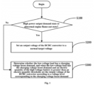
- FIG. 1 is a flowchart of a DCDC output voltage control method according to an embodiment of the present invention.
- the DCDC output voltage control method of the present invention is used in a hybrid electric vehicle, the vehicle including a DCDC converter for converting the voltage of a high-voltage battery into a low voltage used for a low-voltage load of the vehicle in a buck operation mode and outputting the low voltage.
- the method includes:
- the DCDC converter of this embodiment determines the charging demand of the low-voltage load when the vehicle is neither in a high power output demand state nor in an abnormal engine flame-out state. If the low-voltage load has a charging voltage boost demand and the electric quantity of the high-voltage battery is greater than an electric quantity threshold at this time, a corresponding output voltage is set according to the voltage level corresponding to the specific situation of the charging voltage boost demand. However, when the vehicle is in the high power output demand state or the abnormal engine flame-out state, the output voltage of the DCDC converter will not be boosted. That is, the setting mode of the output voltage of the DCDC converter is specifically defined. The output voltage of the DCDC converter is controlled and adjusted according to the operating state of the vehicle and the low-voltage load, which can optimize the fuel economy of a hybrid power assembly system.
- the setting of the output voltage of the DCDC converter according to the voltage level corresponding to the charging voltage boost demand can meet the charging demand of the low-voltage load under different charging voltage boost demands, which further ensures the fuel economy of the vehicle.
- FIG. 2 is a flowchart of a DCDC output voltage control method according to another embodiment of the present invention.
- the method further includes:
- the vehicle when the vehicle is in the DCDC enable state and receives the buck request instruction, the vehicle enters a delay state, that is, the DCDC converter will not immediately enter the buck operation mode, but will delay for a period of time to boost the voltage and prepare for voltage conversion. As soon as the delay time comes, the state of the DCDC converter is transitioned to the buck operation mode. Of course, there should be no fault to prohibit voltage conversion during this process. Once such a fault occurs, for example, the hardware of the DCDC converter crashes, the DCDC converter stops operating, so as to ensure the normal conversion of voltage.
- the configuration of the delay state can ensure that the DCDC converter has prepared for voltage conversion when entering the buck operation mode, thereby ensuring the smooth progress of the buck operation.
- step S20 includes a process of determining a pre-enable state and an enable state. It is determined that the DCDC converter is in the pre-enable state when the high-voltage battery of the vehicle is in a state of being able to supply power, the vehicle receives a start request instruction, the high-voltage battery is in a state of being able to maintain a preset electric quantity, the DCDC converter is in a state of being able to normally transmit and receive signals, and a high-voltage system is not faulty.
- the high-voltage battery is in the state of being able to supply power when an engine electronic control module (ECM) of the vehicle has sent a request for pull-in of a main relay of the high-voltage battery to a power battery energy control module (BECM) and the ECM has received information fed back by the BECM that the main relay of the high-voltage battery has been pulled in.
- ECM engine electronic control module
- BECM power battery energy control module
- the start request instruction is a start request input by a driver or a remote start request. At this time, the vehicle is in a state where some low-voltage accessories are powered on but not turned on.
- the DCDC converter is in the state of being able to normally transmit and receive signals.
- the DCDC converter When the DCDC converter is in the pre-enable state, if an ignition signal (KL15 power-on) is received and it is determined that a motor of the vehicle is not faulty, it is determined that the DCDC converter is in the enable state, that is, the DCDC enable state.
- KL15 power-on an ignition signal
- This embodiment defines the DCDC enable state. At this time, the DCDC converter is in a state where it has been powered on and can normally transmit and receive signals, that is, an initial state where a voltage conversion request has not been received.
- the high power output demand state includes at least one of an initiation start state, a full-throttle acceleration state, an operating high-throttle start state and a crawling start in-gear state. That is, the step of determining whether the vehicle is in a high power output demand state or an abnormal engine flame-out state in step S100 includes: Step S102, it is determined whether the vehicle is in at least one of the initiation start state, the full-throttle acceleration state, the operating high-throttle start state, the crawling start in-gear state, and the abnormal engine flame-out state.
- the vehicle is in the initiation start state when, in a same driving cycle, a first start time of the engine of the vehicle is less than a first limit or a non-first start time thereof is less than a second limit, wherein the first limit is greater than the second limit.
- the first limit is any value between 10s and 20s
- the second limit is any value within 5 to 10 s. Because the power consumption for the first start is higher, the first limit should be set larger.
- the power consumption is relatively high, so the power consumption of the load needs to be reduced, and the event that the DCDC converter boosts the output voltage cannot be triggered.
- the vehicle is in the full-throttle acceleration state when the opening of a throttle pedal of the vehicle is greater than a first opening limit, the vehicle is in a forward gear or a reverse gear, and the time when the opening of the throttle pedal is greater than the first opening limit is less than a third limit.
- the first opening limit is defined as a full-throttle acceleration limit of the vehicle, that is, when the opening of the throttle pedal is greater than the first opening limit, it indicates that the vehicle has a demand for full-throttle acceleration.
- a vehicle speed is less than a starting vehicle speed threshold
- a reserve torque of the engine is less than a torque threshold
- the opening of the throttle pedal of the vehicle is greater than a second opening limit
- a difference between a maximum torque of the engine and a driver request torque is less than a difference threshold
- a current power of an air condition compressor is greater than a power limit.
- the reserve torque is a difference between the maximum torque and a current actual torque of the engine.
- the vehicle speed threshold is 20 kph
- the second opening limit is 5%
- the difference threshold is 50 Nm
- the torque threshold is any value between 50 and 100 Nm.
- a starting time is less than a fourth limit
- the vehicle speed is less than the starting vehicle speed threshold
- the reserve torque of the engine is less than the torque threshold
- opening information of the throttle pedal is not received
- the vehicle is in the forward gear or the reverse gear.
- the fourth limit is 1000 s.
- a rotation speed of the engine is less than a target idle speed and the absolute value of a difference between the two is greater than a rotation speed difference limit
- a rotation speed acceleration of the engine is negative and the absolute value of the rotation speed acceleration is less than an acceleration limit
- a predicted rotation speed of the engine is less than a flame-out rotation speed threshold.
- the target idle speed is 400 rpm
- the acceleration limit is 5 rpm/s
- the flame-out rotation speed threshold is 500 rpm.
- the predicted rotation speed of the engine refers to a next rotation speed predicted according to a current rotation speed and the rotation speed acceleration.
- the method when the vehicle is in the high power output demand state or the abnormal engine flame-out state, the method further includes: Step S250, a request for reducing the power of the low-voltage load is sent. For example, some accessories are controlled to close, the opening of a fan is reduced, the power of an air conditioner is reduced, etc., so as to reduce the power consumption of the low-voltage load as much as possible when the vehicle is in the high power output demand state or the abnormal engine flame-out state, thereby ensuring the basic operation demand of the vehicle.
- the step of determining whether the low-voltage load has a charging voltage boost demand in step S300 includes: Step S302, whether one of the conditions of a catalytic converter of the vehicle being in a rapid heating demand state, an oil pump of the vehicle being in a high load demand state, and a fan of the vehicle being in a high load state occurs is determined, and if so, it is determined that the low-voltage load has the charging voltage boost demand.
- the catalytic converter is in the rapid heating demand state when the temperature of a coolant in the engine of the vehicle is higher than a temperature threshold, an upstream exhaust temperature of the catalytic converter is reliable, and the exhaust temperature is lower than an air temperature threshold.
- the temperature threshold is 18°
- the air temperature threshold is 170°. Whether the exhaust temperature is reliable can be determined by the accuracy of signals.
- the opening of the fan when the opening of the fan is greater than an opening threshold, it is determined that the fan is in the high load state.
- the opening threshold is 60%.
- the fan here refers to a fan of a thermal management system of the vehicle.
- the step of setting the output voltage of the DCDC converter according to a voltage level corresponding to the charging voltage boost demand in step S300 includes:
- the voltage level corresponding to the catalytic converter being in the rapid heating demand state is lower than the voltage level corresponding to the oil pump being in the high load demand state.
- the voltage level corresponding to the oil pump being in the high load demand state is the same as the voltage level corresponding to the fan being in the high load state.
- a corresponding output voltage can be determined according to the voltage level.
- both the voltage levels corresponding to the oil pump being in the high load demand state and the fan being in the high load state are set to 3, and the corresponding output voltage of the DCDC converter is 15.2 V; the voltage level corresponding to the catalytic converter being in the rapid heating demand state is set to 2, and the corresponding output voltage of the DCDC converter is 14 V.
- the voltage levels are not limited to the above two, but can further include level 0 and level 1, which correspond to 12.2 to 15 V (that is, the above normal target voltage) and 13.6 V, respectively, to deal with other vehicle states.
- the classification of voltage levels is not limited to this, and there is no restriction here.
- the present invention further provides a DCDC output voltage control system for a hybrid electric vehicle, including a control unit.
- the control unit includes a memory and a processor, and the memory storing a control program that, when executed by the processor, is used to implement the DCDC output voltage control method according to any one or a combination of the above embodiments.
- the processor may be a central processing unit (CPU), or a digital processing unit, etc.
- the processor transmits and receives data through a communication interface.
- the memory is configured to store programs executed by the processor.
- the memory is any medium that can be used to carry or store desired program codes in the form of instructions or data structures and that can be accessed by a computer, and can also be a combination of a plurality of memories.
- the aforementioned computer program may be downloaded from a computer-readable storage medium to a corresponding computing/processing device or downloaded to a computer or an external storage device via a network (such as the Internet, a local area network, a wide area network, and/or a wireless network).
- a network such as the Internet, a local area network, a wide area network, and/or a wireless network.
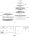
- FIG. 3 is a schematic diagram of a DCDC output voltage control system according to an embodiment of the present invention.
- the hybrid electric vehicle includes a power battery energy control module (BECM), an engine electronic control module (ECM), a motor controller (IGM), a gateway (VDDM), a vehicle electronics controller (CEM) and a 12 V battery voltage sensor.
- BECM power battery energy control module
- ECM engine electronic control module
- IGM motor controller
- VDDM gateway
- CEM vehicle electronics controller
- the engine electronic control module is in communication connection with the power battery energy control module, and can acquire, through the battery energy control module, information about whether a main relay of a high-voltage battery is pulled in. For example, the engine electronic control module sends a high-voltage battery pull-in request to the power battery energy control module, and determines that the main relay of the high-voltage battery has been pulled in when receiving pulled-in information fed back by the power battery energy control module.
- the engine electronic control module is also in communication connection with the motor controller, and sends a DCDC enable request to the motor controller.
- the motor controller is configured to monitor whether the DCDC converter is in an enable state and feed enable state information back to the engine electronic control module. After receiving state information that the DCDC converter has been enabled, the engine electronic control module determines a voltage level of the DCDC converter according to the state of the vehicle.
- the engine electronic control module is further configured to send the voltage level to the vehicle electronics controller through the gateway so that the vehicle electronics controller sets an output voltage of the DCDC converter according to a battery state fed back by the 12 V battery voltage sensor and the voltage level, and to forward the set output voltage to the motor controller through the gateway so that the motor controller controls the DCDC converter to output a voltage according to the set output voltage.
Landscapes
- Engineering & Computer Science (AREA)
- Power Engineering (AREA)
- Transportation (AREA)
- Mechanical Engineering (AREA)
- Life Sciences & Earth Sciences (AREA)
- Sustainable Development (AREA)
- Sustainable Energy (AREA)
- Chemical & Material Sciences (AREA)
- Combustion & Propulsion (AREA)
- Electric Propulsion And Braking For Vehicles (AREA)
- Hybrid Electric Vehicles (AREA)
Claims (11)
- Verfahren zur Steuerung der DCDC-Ausgangsspannung für ein Hybrid-Elektrofahrzeug, wobei das Fahrzeug einen DCDC-Wandler zum Umwandeln einer Spannung einer Hochspannungsbatterie in eine Niederspannung in einer Abwärtsbetriebsart und zum Ausgeben der Niederspannung umfasst, wobei die Niederspannung für eine Niederspannungslast einschließlich einer 12-V-Batterie des Fahrzeugs verwendet wird, wobei das Verfahren umfasst:Bestimmen, ob sich das Fahrzeug in einem Zustand mit hohem Leistungsbedarf oder in einem anormalen Motorausfallzustand befindet (S100), wenn sich der DCDC-Wandler in der Abwärtsbetriebsart befindet;Wenn ja, Einstellen einer Ausgangsspannung des DCDC-Wandlers auf eine normale Zielspannung, um den DCDC-Wandler so zu steuern, dass er gemäß der normalen Zielspannung ausgibt (S200), wobei die normale Zielspannung ein Spannungswert innerhalb von 12,2-15 V ist, die gemäß dem SOC und dem Lade- und Entladestrom der 12-V-Batterie eingestellt wird;andernfalls Bestimmen, ob die Niederspannungslast eine Ladespannungserhöhungsanforderung hat, und wenn die Niederspannungslast die Ladespannungserhöhungsanforderung hat und der SOC der Hochspannungsbatterie größer als ein Schwellenwert für die elektrische Menge ist, Einstellen der Ausgangsspannung des DCDC-Wandlers gemäß einem Spannungspegel, der der Ladespannungserhöhungsanforderung entspricht, um eine Ladeanforderung der Niederspannungslast zu erfüllen (S300);wobei ein Schritt des Bestimmens, ob sich das Fahrzeug in einem anormalen Motorausfallzustand befindet, umfasst:Bestimmen, dass sich das Fahrzeug in dem anormalen Motorausfallzustand befindet, wenn sich der Motor des Fahrzeugs in einem Betriebszustand befindet, eine Drehzahl des Motors kleiner als eine Soll-Leerlaufdrehzahl ist und der Absolutwert einer Differenz zwischen den beiden größer als ein Drehzahldifferenzgrenzwert ist, eine Drehzahlbeschleunigung des Motors negativ ist und der Absolutwert der Drehzahlbeschleunigung kleiner als ein Beschleunigungsgrenzwert ist, und eine vorhergesagte Drehzahl des Motors kleiner als ein Flammenausfall-Drehzahlschwellenwert ist;wobei der Schritt des Bestimmens, ob die Niederspannungslast eine Ladespannungserhöhungsanforderung hat, umfasst:Bestimmen, ob sich ein Katalysator des Fahrzeugs in einem Zustand mit schnellem Heizbedarf befindet;Bestimmen, ob sich eine Ölpumpe des Fahrzeugs in einem Zustand hoher Lastanforderung befindet;Bestimmen, ob sich ein Lüfter des Fahrzeugs in einem Hochlastzustand befindet; UndBestimmen, dass die Niederspannungslast die Ladespannungserhöhungsanforderung hat, wenn eine oder mehrere Bedingungen des Katalysators, der sich in einem Zustand mit schnellem Heizbedarf befindet, der Ölpumpe, die sich im Hochlastanforderungszustand befindet, und des Lüfters, der sich im Hochlastzustand befindet, auftreten (S302); undwobei der Schritt des Einstellens der Ausgangsspannung des DCDC-Wandlers gemäß einem Spannungspegel, der der Ladespannungserhöhungsanforderung entspricht, umfasst:Steuern des DCDC-Wandlers, um eine Spannung gemäß dem Spannungspegel auszugeben, der der auftretenden Bedingung entspricht, wenn eine der Bedingungen des Katalysators, der sich im in einem Zustand mit schnellem Heizbedarf befindet, der Ölpumpe, die sich im Hochlastanforderungszustand befindet, und des Lüfters, der sich im Hochlastzustand befindet, auftritt (S304); oderSteuern des DCDC-Wandlers, um eine Spannung gemäß einem höchsten Spannungspegel unter den Spannungspegeln, die den auftretenden Bedingungen entsprechen, auszugeben, wenn mindestens zwei Bedingungen des Katalysators, der sich in einem Zustand mit schnellem Heizbedarf befindet, der Ölpumpe, die sich im Hochlastanforderungszustand befindet, und des Lüfters, der sich im Hochlastzustand befindet, auftreten (S306), wobei der Spannungspegel, der dem Katalysator entspricht, der sich in einem Zustand mit schnellem Heizbedarf befindet, niedriger ist als der Spannungspegel, der der Ölpumpe entspricht, die sich im Hochlastanforderungszustand befindet, und der Spannungspegel, der der Ölpumpe entspricht, die sich im Hochlastanforderungszustand befindet, der gleiche ist wie der Spannungspegel, der dem Lüfter entspricht, der sich im Hochlastzustand befindet.
- Verfahren zur Steuerung der DCDC-Ausgangsspannung nach Anspruch 1, wobei das Verfahren vor dem Schritt, bei dem, wenn sich der DCDC-Wandler in der Abwärtsbetriebsart befindet, Bestimmen, ob sich das Fahrzeug in einem Zustand mit hohem Leistungsbedarf oder in einem anormalen Motorflammzustand befindet, ferner umfasst:Bestimmen, ob sich das Fahrzeug in einem DCDC-Freigabezustand befindet (S20); undSteuern des DCDC-Wandlers, um die Spannungsumwandlung vorzubereiten, wenn sich das Fahrzeug im Freigabezustand befindet und einen Abwärtsanforderungsbefehl empfängt, und Durchführen der Zeitmessung und Steuern des DCDC-Wandlers, um in die Abwärtsbetriebsart zu wechseln, wenn die Zeit eine voreingestellte Verzögerungszeit erreicht (S60).
- Verfahren zur Steuerung der DCDC-Ausgangsspannung nach Anspruch 2, wobei der Schritt des Bestimmens, ob sich das Fahrzeug in einem DCDC-Freigabezustand befindet, umfasst:Bestimmen, dass sich der DCDC-Wandler in einem Vorfreigabezustand befindet, wenn sich die Hochspannungsbatterie des Fahrzeugs in einem Zustand befindet, in dem sie in der Lage ist, Strom zu liefern, wenn das Fahrzeug einen Startanforderungsbefehl empfängt, wenn die Hochspannungsbatterie sich in einem Zustand befindet, in dem sie in der Lage ist, einen voreingestellten SOC aufrechtzuerhalten, wenn der DCDC-Wandler sich in einem Zustand befindet, in dem er in der Lage ist, normalerweise Signale zu senden und zu empfangen, und wenn ein Hochspannungssystem nicht fehlerhaft ist; undBestimmen, dass der DCDC-Wandler im Freigabezustand ist, wenn der DCDC-Wandler im Vorfreigabezustand ist, ein Zündsignal empfangen wird und festgestellt wird, dass ein Motor des Fahrzeugs nicht fehlerhaft ist.
- Verfahren zur Steuerung der DCDC-Ausgangsspannung nach einem der Ansprüche 1 bis 3, wobei der Zustand mit hohem Leistungsbedarf mindestens einen der folgenden Zustände umfasst: einen Startzustand, einen Vollgas-Beschleunigungszustand, einen Betriebs-Hochgas-Startzustand und einen Kriechstartzustand mit eingelegtem Gang.
- Verfahren zur Steuerung der DCDC-Ausgangsspannung nach Anspruch 4, wobei der Schritt des Bestimmens, ob sich das Fahrzeug in einem Zustand mit hohem Leistungsbedarf befindet, umfasst:
Bestimmen, dass sich das Fahrzeug in dem Startzustand befindet, wenn in einem gleichen Fahrzyklus eine erste Startzeit eines Motors des Fahrzeugs kleiner als ein erster Grenzwert ist oder eine Nicht-Erststartzeit davon kleiner als ein zweiter Grenzwert ist, wobei der erste Grenzwert größer als der zweite Grenzwert ist. - Verfahren zur Steuerung der DCDC-Ausgangsspannung nach Anspruch 4, wobei der Schritt des Bestimmens, ob sich das Fahrzeug in einem Zustand mit hohem Leistungsbedarf befindet, umfasst:
Bestimmen, dass sich das Fahrzeug im Vollgas-Beschleunigungszustand befindet, wenn eine Öffnung eines Gaspedals des Fahrzeugs größer als ein erster Öffnungsgrenzwert ist, sich das Fahrzeug in einem Vorwärtsgang oder einem Rückwärtsgang befindet, und die Zeit, in der die Öffnung des Gaspedal größer als der erste Öffnungsgrenzwert ist, kleiner als ein dritter Grenzwert ist. - Verfahren zur Steuerung der DCDC-Ausgangsspannung nach Anspruch 4, wobei der Schritt des Bestimmens, ob sich das Fahrzeug in einem Zustand mit hohem Leistungsbedarf befindet, umfasst:
Bestimmen, dass sich das Fahrzeug in dem Betriebs-Hochgas-Startzustand befindet, wenn sich der Motor des Fahrzeugs in einem Betriebszustand befindet, eine Fahrzeuggeschwindigkeit geringer ist als ein Schwellenwert für die Startgeschwindigkeit des Fahrzeugs, ein Reservedrehmoment des Motors geringer ist als ein Drehmomentschwellenwert, eine Öffnung eines Gaspedals des Fahrzeugs größer ist als ein zweiter Öffnungsgrenzwert, eine Differenz zwischen einem maximalen Drehmoment des Motors und einem vom Fahrer angeforderten Drehmoment geringer ist als ein Differenzschwellenwert, und eine aktuelle Leistung eines Klimakompressors größer ist als ein Leistungsgrenzwert. - Verfahren zur Steuerung der DCDC-Ausgangsspannung nach Anspruch 4, wobei der Schritt des Bestimmens, ob sich das Fahrzeug in einem Zustand mit hohem Leistungsbedarf befindet, umfasst:
Bestimmen, dass sich das Fahrzeug im Kriechstartzustand mit eingelegtem Gang befindet, wenn sich der Motor des Fahrzeugs in einem Betriebszustand befindet, eine Startzeit kleiner als ein vierter Grenzwert ist, eine Fahrzeuggeschwindigkeit kleiner als ein Schwellenwert für die Startgeschwindigkeit des Fahrzeugs ist, ein Reservedrehmoment des Motors kleiner als ein Drehmomentschwellenwert ist, eine Öffnungsinformation eines Gaspedals nicht empfangen wird und sich das Fahrzeug in einem Vorwärtsgang oder einem Rückwärtsgang befindet. - Verfahren zur Steuerung der DCDC-Ausgangsspannung nach Anspruch 1, wobei der Schritt des Bestimmens, ob sich ein Katalysator des Fahrzeugs in einem Zustand mit schnellem Heizbedarf befindet, umfasst:
Bestimmen, dass sich der Katalysator in einem Zustand mit schnellem Heizbedarf befindet, wenn die Temperatur eines Kühlmittels im Motor des Fahrzeugs höher als ein Temperaturschwellenwert ist, eine stromaufwärts gelegene Abgastemperatur des Katalysators zuverlässig ist und die Abgastemperatur niedriger als ein Lufttemperaturschwellenwert ist. - Verfahren zur Steuerung der DCDC-Ausgangsspannung nach Anspruch 1, wobei der Schritt des Bestimmens, ob sich eine Ölpumpe des Fahrzeugs in einem Hochlastanforderungszustand befindet, umfasst:Bestimmen, dass sich die Ölpumpe im Hochlastanforderungszustand befindet, wenn eine Last der Ölpumpe größer als ein Lastschwellenwert ist; und/oderwobei der Schritt des Bestimmen, ob sich ein Lüfter des Fahrzeugs in einem Hochlastzustand befindet, umfasst:
Bestimmen, dass sich der Lüfter im Hochlastzustand befindet, wenn eine Öffnung des Lüfters größer als ein Öffnungsschwellenwert ist. - System zur Steuerung der DCDC-Ausgangsspannung für ein Hybrid-Elektrofahrzeug, das eine Steuereinheit umfasst, wobei die Steuereinheit einen Speicher und einen Prozessor umfasst, wobei der Speicher ein Steuerprogramm speichert, das, wenn es von dem Prozessor ausgeführt wird, verwendet wird, um das Verfahrren zur Steuerung der DCDC-Ausgangsspannung nach einem der Ansprüche 1 bis 10 zu implementieren.
Applications Claiming Priority (1)
| Application Number | Priority Date | Filing Date | Title |
|---|---|---|---|
| PCT/CN2021/111719 WO2023015433A1 (zh) | 2021-08-10 | 2021-08-10 | 混合动力车辆的dcdc输出电压控制方法及控制系统 |
Publications (3)
| Publication Number | Publication Date |
|---|---|
| EP4159518A4 EP4159518A4 (de) | 2023-04-05 |
| EP4159518A1 EP4159518A1 (de) | 2023-04-05 |
| EP4159518B1 true EP4159518B1 (de) | 2024-05-01 |
Family
ID=80382119
Family Applications (1)
| Application Number | Title | Priority Date | Filing Date |
|---|---|---|---|
| EP21873706.2A Active EP4159518B1 (de) | 2021-08-10 | 2021-08-10 | Gleichstromausgangsspannungssteuerverfahren und -steuersystem für hybridfahrzeug |
Country Status (4)
| Country | Link |
|---|---|
| US (1) | US12539839B2 (de) |
| EP (1) | EP4159518B1 (de) |
| CN (1) | CN114144327B (de) |
| WO (1) | WO2023015433A1 (de) |
Families Citing this family (3)
| Publication number | Priority date | Publication date | Assignee | Title |
|---|---|---|---|---|
| CN115230455B (zh) * | 2022-07-12 | 2024-06-04 | 一汽解放汽车有限公司 | 车辆混动系统 |
| CN115257458B (zh) * | 2022-08-24 | 2024-10-11 | 中国第一汽车股份有限公司 | Dcdc转化器的控制方法、控制装置及车辆 |
| CN119305627A (zh) * | 2024-11-07 | 2025-01-14 | 中通客车股份有限公司 | 一种新能源车辆转向助力控制方法及系统 |
Citations (1)
| Publication number | Priority date | Publication date | Assignee | Title |
|---|---|---|---|---|
| US20200079231A1 (en) * | 2009-12-04 | 2020-03-12 | Hyundai Motor Company | Method for controlling charging voltage of 12v auxiliary battery for hybrid vehicle |
Family Cites Families (11)
| Publication number | Priority date | Publication date | Assignee | Title |
|---|---|---|---|---|
| JP2010136509A (ja) | 2008-12-03 | 2010-06-17 | Toyota Motor Corp | 車両およびその制御方法 |
| KR101103877B1 (ko) | 2009-07-30 | 2012-01-12 | 현대자동차주식회사 | 하이브리드차량의 가변 전압 제어 방법 |
| CN104228819B (zh) | 2014-09-30 | 2016-08-24 | 重庆长安汽车股份有限公司 | 一种汽车48v系统的dcdc控制系统及方法 |
| KR101628516B1 (ko) | 2014-11-05 | 2016-06-08 | 현대자동차주식회사 | 하이브리드 차량의 직류변환장치 전압 가변제어 방법 |
| KR101693956B1 (ko) | 2015-01-12 | 2017-01-06 | 현대자동차주식회사 | 하이브리드 차량의 저전압 직류컨버터 전압 가변제어 방법 |
| US9761913B2 (en) * | 2015-08-26 | 2017-09-12 | Solarcity Corporation | High efficiency high voltage battery pack for onsite power generation systems |
| CN205554092U (zh) | 2016-04-14 | 2016-09-07 | 罗伯特·博世有限公司 | Dc/dc转换器、电池能量管理系统及混合动力车辆 |
| CN109080560B (zh) * | 2018-08-27 | 2021-08-03 | 上海精虹新能源科技有限公司 | 一种纯电动汽车dcdc控制系统及控制方法 |
| JP7136024B2 (ja) * | 2019-07-05 | 2022-09-13 | トヨタ自動車株式会社 | Dcdcコンバータの制御装置 |
| CN111114324A (zh) | 2020-01-07 | 2020-05-08 | 吉利汽车研究院(宁波)有限公司 | 一种混合动力车辆的充电方法、装置、终端及存储介质 |
| CN112583068B (zh) * | 2020-11-04 | 2023-09-22 | 长城汽车股份有限公司 | 一种直流/直流dc/dc变换器的控制方法及系统 |
-
2021
- 2021-08-10 CN CN202180004525.0A patent/CN114144327B/zh active Active
- 2021-08-10 WO PCT/CN2021/111719 patent/WO2023015433A1/zh not_active Ceased
- 2021-08-10 EP EP21873706.2A patent/EP4159518B1/de active Active
- 2021-08-10 US US18/287,920 patent/US12539839B2/en active Active
Patent Citations (1)
| Publication number | Priority date | Publication date | Assignee | Title |
|---|---|---|---|---|
| US20200079231A1 (en) * | 2009-12-04 | 2020-03-12 | Hyundai Motor Company | Method for controlling charging voltage of 12v auxiliary battery for hybrid vehicle |
Also Published As
| Publication number | Publication date |
|---|---|
| CN114144327B (zh) | 2025-11-28 |
| US20240190413A1 (en) | 2024-06-13 |
| CN114144327A (zh) | 2022-03-04 |
| EP4159518A4 (de) | 2023-04-05 |
| US12539839B2 (en) | 2026-02-03 |
| WO2023015433A1 (zh) | 2023-02-16 |
| EP4159518A1 (de) | 2023-04-05 |
Similar Documents
| Publication | Publication Date | Title |
|---|---|---|
| EP4032737B1 (de) | Hybridfahrzeug und steuerungsverfahren und -system nach ausfall der hybridfahrzeugbatterie | |
| EP4159518B1 (de) | Gleichstromausgangsspannungssteuerverfahren und -steuersystem für hybridfahrzeug | |
| JP5074876B2 (ja) | ハイブリッド車両のアイドルストップモード制御方法 | |
| US8761977B2 (en) | Method and apparatus for optimizing engine idle speed in a vehicle | |
| US20180233943A1 (en) | Power supply system for vehicle | |
| EP2159409A2 (de) | Anlasshilfssystem für ein Fahrzeug | |
| US9694692B2 (en) | Vehicle controlling system | |
| KR100867795B1 (ko) | 하이브리드 차량의 dc/dc 컨버터 운전 제어 방법 | |
| US8457825B2 (en) | Method and apparatus for operating a powertrain system in response to accessory load | |
| US20080146411A1 (en) | Method for controlling engine torque of hybrid electric vehicle with electronic throttle control | |
| JP7351175B2 (ja) | ハイブリッド車両の充電制御方法及びハイブリッド車両の充電制御装置 | |
| US10910972B2 (en) | Control apparatus and onboard system | |
| US8275504B2 (en) | Stabilization apparatus and method for stabling load voltage of vehicle | |
| US20050206350A1 (en) | Vehicle generator and vehicle generating system | |
| CN111969898B (zh) | 新能源汽车永磁同步电机控制器及控制方法 | |
| CN115366831B (zh) | 车辆怠速工况下的能耗管理方法、装置、车辆及存储介质 | |
| JP2013194707A (ja) | エンジン駆動補機制御装置 | |
| CN115622210A (zh) | 用于双能量存储的能量管理的设备和方法 | |
| US12606025B2 (en) | Techniques for controlling energy consumption and enhancing systemic efficiency through management of thermal devices for electrified vehicles | |
| CN114248753A (zh) | 混合动力车辆的控制方法和装置、介质、设备、车辆 | |
| JP7768110B2 (ja) | 電力制御装置 | |
| US20260084689A1 (en) | Control device for hybrid electric vehicle | |
| US20250303917A1 (en) | Techniques for ensuring propulsion system enablement and low voltage system protection by supervising thermal devices in electrified vehicles | |
| US9834194B2 (en) | Method and system for enabling electrical loads during an engine auto start | |
| KR20030089895A (ko) | 하이브리드 전기자동차의 인터페이스장치 |
Legal Events
| Date | Code | Title | Description |
|---|---|---|---|
| STAA | Information on the status of an ep patent application or granted ep patent |
Free format text: STATUS: UNKNOWN |
|
| STAA | Information on the status of an ep patent application or granted ep patent |
Free format text: STATUS: THE INTERNATIONAL PUBLICATION HAS BEEN MADE |
|
| PUAI | Public reference made under article 153(3) epc to a published international application that has entered the european phase |
Free format text: ORIGINAL CODE: 0009012 |
|
| STAA | Information on the status of an ep patent application or granted ep patent |
Free format text: STATUS: REQUEST FOR EXAMINATION WAS MADE |
|
| STAA | Information on the status of an ep patent application or granted ep patent |
Free format text: STATUS: EXAMINATION IS IN PROGRESS |
|
| 17P | Request for examination filed |
Effective date: 20220407 |
|
| A4 | Supplementary search report drawn up and despatched |
Effective date: 20230125 |
|
| AK | Designated contracting states |
Kind code of ref document: A1 Designated state(s): AL AT BE BG CH CY CZ DE DK EE ES FI FR GB GR HR HU IE IS IT LI LT LU LV MC MK MT NL NO PL PT RO RS SE SI SK SM TR |
|
| 17Q | First examination report despatched |
Effective date: 20230316 |
|
| GRAP | Despatch of communication of intention to grant a patent |
Free format text: ORIGINAL CODE: EPIDOSNIGR1 |
|
| STAA | Information on the status of an ep patent application or granted ep patent |
Free format text: STATUS: GRANT OF PATENT IS INTENDED |
|
| DAV | Request for validation of the european patent (deleted) | ||
| DAX | Request for extension of the european patent (deleted) | ||
| INTG | Intention to grant announced |
Effective date: 20231213 |
|
| GRAS | Grant fee paid |
Free format text: ORIGINAL CODE: EPIDOSNIGR3 |
|
| GRAA | (expected) grant |
Free format text: ORIGINAL CODE: 0009210 |
|
| STAA | Information on the status of an ep patent application or granted ep patent |
Free format text: STATUS: THE PATENT HAS BEEN GRANTED |
|
| AK | Designated contracting states |
Kind code of ref document: B1 Designated state(s): AL AT BE BG CH CY CZ DE DK EE ES FI FR GB GR HR HU IE IS IT LI LT LU LV MC MK MT NL NO PL PT RO RS SE SI SK SM TR |
|
| REG | Reference to a national code |
Ref country code: GB Ref legal event code: FG4D |
|
| REG | Reference to a national code |
Ref country code: CH Ref legal event code: EP |
|
| REG | Reference to a national code |
Ref country code: DE Ref legal event code: R096 Ref document number: 602021012876 Country of ref document: DE |
|
| REG | Reference to a national code |
Ref country code: IE Ref legal event code: FG4D |
|
| REG | Reference to a national code |
Ref country code: NL Ref legal event code: FP |
|
| REG | Reference to a national code |
Ref country code: LT Ref legal event code: MG9D |
|
| PG25 | Lapsed in a contracting state [announced via postgrant information from national office to epo] |
Ref country code: IS Free format text: LAPSE BECAUSE OF FAILURE TO SUBMIT A TRANSLATION OF THE DESCRIPTION OR TO PAY THE FEE WITHIN THE PRESCRIBED TIME-LIMIT Effective date: 20240901 |
|
| PG25 | Lapsed in a contracting state [announced via postgrant information from national office to epo] |
Ref country code: BG Free format text: LAPSE BECAUSE OF FAILURE TO SUBMIT A TRANSLATION OF THE DESCRIPTION OR TO PAY THE FEE WITHIN THE PRESCRIBED TIME-LIMIT Effective date: 20240501 |
|
| PG25 | Lapsed in a contracting state [announced via postgrant information from national office to epo] |
Ref country code: HR Free format text: LAPSE BECAUSE OF FAILURE TO SUBMIT A TRANSLATION OF THE DESCRIPTION OR TO PAY THE FEE WITHIN THE PRESCRIBED TIME-LIMIT Effective date: 20240501 Ref country code: FI Free format text: LAPSE BECAUSE OF FAILURE TO SUBMIT A TRANSLATION OF THE DESCRIPTION OR TO PAY THE FEE WITHIN THE PRESCRIBED TIME-LIMIT Effective date: 20240501 |
|
| PG25 | Lapsed in a contracting state [announced via postgrant information from national office to epo] |
Ref country code: GR Free format text: LAPSE BECAUSE OF FAILURE TO SUBMIT A TRANSLATION OF THE DESCRIPTION OR TO PAY THE FEE WITHIN THE PRESCRIBED TIME-LIMIT Effective date: 20240802 |
|
| PG25 | Lapsed in a contracting state [announced via postgrant information from national office to epo] |
Ref country code: PT Free format text: LAPSE BECAUSE OF FAILURE TO SUBMIT A TRANSLATION OF THE DESCRIPTION OR TO PAY THE FEE WITHIN THE PRESCRIBED TIME-LIMIT Effective date: 20240902 |
|
| REG | Reference to a national code |
Ref country code: AT Ref legal event code: MK05 Ref document number: 1681915 Country of ref document: AT Kind code of ref document: T Effective date: 20240501 |
|
| PG25 | Lapsed in a contracting state [announced via postgrant information from national office to epo] |
Ref country code: ES Free format text: LAPSE BECAUSE OF FAILURE TO SUBMIT A TRANSLATION OF THE DESCRIPTION OR TO PAY THE FEE WITHIN THE PRESCRIBED TIME-LIMIT Effective date: 20240501 |
|
| PG25 | Lapsed in a contracting state [announced via postgrant information from national office to epo] |
Ref country code: AT Free format text: LAPSE BECAUSE OF FAILURE TO SUBMIT A TRANSLATION OF THE DESCRIPTION OR TO PAY THE FEE WITHIN THE PRESCRIBED TIME-LIMIT Effective date: 20240501 |
|
| PG25 | Lapsed in a contracting state [announced via postgrant information from national office to epo] |
Ref country code: PL Free format text: LAPSE BECAUSE OF FAILURE TO SUBMIT A TRANSLATION OF THE DESCRIPTION OR TO PAY THE FEE WITHIN THE PRESCRIBED TIME-LIMIT Effective date: 20240501 |
|
| PG25 | Lapsed in a contracting state [announced via postgrant information from national office to epo] |
Ref country code: LV Free format text: LAPSE BECAUSE OF FAILURE TO SUBMIT A TRANSLATION OF THE DESCRIPTION OR TO PAY THE FEE WITHIN THE PRESCRIBED TIME-LIMIT Effective date: 20240501 |
|
| PG25 | Lapsed in a contracting state [announced via postgrant information from national office to epo] |
Ref country code: PT Free format text: LAPSE BECAUSE OF FAILURE TO SUBMIT A TRANSLATION OF THE DESCRIPTION OR TO PAY THE FEE WITHIN THE PRESCRIBED TIME-LIMIT Effective date: 20240902 Ref country code: PL Free format text: LAPSE BECAUSE OF FAILURE TO SUBMIT A TRANSLATION OF THE DESCRIPTION OR TO PAY THE FEE WITHIN THE PRESCRIBED TIME-LIMIT Effective date: 20240501 Ref country code: NO Free format text: LAPSE BECAUSE OF FAILURE TO SUBMIT A TRANSLATION OF THE DESCRIPTION OR TO PAY THE FEE WITHIN THE PRESCRIBED TIME-LIMIT Effective date: 20240801 Ref country code: LV Free format text: LAPSE BECAUSE OF FAILURE TO SUBMIT A TRANSLATION OF THE DESCRIPTION OR TO PAY THE FEE WITHIN THE PRESCRIBED TIME-LIMIT Effective date: 20240501 Ref country code: IS Free format text: LAPSE BECAUSE OF FAILURE TO SUBMIT A TRANSLATION OF THE DESCRIPTION OR TO PAY THE FEE WITHIN THE PRESCRIBED TIME-LIMIT Effective date: 20240901 Ref country code: HR Free format text: LAPSE BECAUSE OF FAILURE TO SUBMIT A TRANSLATION OF THE DESCRIPTION OR TO PAY THE FEE WITHIN THE PRESCRIBED TIME-LIMIT Effective date: 20240501 Ref country code: GR Free format text: LAPSE BECAUSE OF FAILURE TO SUBMIT A TRANSLATION OF THE DESCRIPTION OR TO PAY THE FEE WITHIN THE PRESCRIBED TIME-LIMIT Effective date: 20240802 Ref country code: FI Free format text: LAPSE BECAUSE OF FAILURE TO SUBMIT A TRANSLATION OF THE DESCRIPTION OR TO PAY THE FEE WITHIN THE PRESCRIBED TIME-LIMIT Effective date: 20240501 Ref country code: ES Free format text: LAPSE BECAUSE OF FAILURE TO SUBMIT A TRANSLATION OF THE DESCRIPTION OR TO PAY THE FEE WITHIN THE PRESCRIBED TIME-LIMIT Effective date: 20240501 Ref country code: BG Free format text: LAPSE BECAUSE OF FAILURE TO SUBMIT A TRANSLATION OF THE DESCRIPTION OR TO PAY THE FEE WITHIN THE PRESCRIBED TIME-LIMIT Effective date: 20240501 Ref country code: AT Free format text: LAPSE BECAUSE OF FAILURE TO SUBMIT A TRANSLATION OF THE DESCRIPTION OR TO PAY THE FEE WITHIN THE PRESCRIBED TIME-LIMIT Effective date: 20240501 Ref country code: RS Free format text: LAPSE BECAUSE OF FAILURE TO SUBMIT A TRANSLATION OF THE DESCRIPTION OR TO PAY THE FEE WITHIN THE PRESCRIBED TIME-LIMIT Effective date: 20240801 |
|
| PG25 | Lapsed in a contracting state [announced via postgrant information from national office to epo] |
Ref country code: DK Free format text: LAPSE BECAUSE OF FAILURE TO SUBMIT A TRANSLATION OF THE DESCRIPTION OR TO PAY THE FEE WITHIN THE PRESCRIBED TIME-LIMIT Effective date: 20240501 |
|
| PG25 | Lapsed in a contracting state [announced via postgrant information from national office to epo] |
Ref country code: EE Free format text: LAPSE BECAUSE OF FAILURE TO SUBMIT A TRANSLATION OF THE DESCRIPTION OR TO PAY THE FEE WITHIN THE PRESCRIBED TIME-LIMIT Effective date: 20240501 |
|
| PG25 | Lapsed in a contracting state [announced via postgrant information from national office to epo] |
Ref country code: CZ Free format text: LAPSE BECAUSE OF FAILURE TO SUBMIT A TRANSLATION OF THE DESCRIPTION OR TO PAY THE FEE WITHIN THE PRESCRIBED TIME-LIMIT Effective date: 20240501 |
|
| PG25 | Lapsed in a contracting state [announced via postgrant information from national office to epo] |
Ref country code: RO Free format text: LAPSE BECAUSE OF FAILURE TO SUBMIT A TRANSLATION OF THE DESCRIPTION OR TO PAY THE FEE WITHIN THE PRESCRIBED TIME-LIMIT Effective date: 20240501 Ref country code: SK Free format text: LAPSE BECAUSE OF FAILURE TO SUBMIT A TRANSLATION OF THE DESCRIPTION OR TO PAY THE FEE WITHIN THE PRESCRIBED TIME-LIMIT Effective date: 20240501 |
|
| PG25 | Lapsed in a contracting state [announced via postgrant information from national office to epo] |
Ref country code: SM Free format text: LAPSE BECAUSE OF FAILURE TO SUBMIT A TRANSLATION OF THE DESCRIPTION OR TO PAY THE FEE WITHIN THE PRESCRIBED TIME-LIMIT Effective date: 20240501 |
|
| PG25 | Lapsed in a contracting state [announced via postgrant information from national office to epo] |
Ref country code: SM Free format text: LAPSE BECAUSE OF FAILURE TO SUBMIT A TRANSLATION OF THE DESCRIPTION OR TO PAY THE FEE WITHIN THE PRESCRIBED TIME-LIMIT Effective date: 20240501 Ref country code: SK Free format text: LAPSE BECAUSE OF FAILURE TO SUBMIT A TRANSLATION OF THE DESCRIPTION OR TO PAY THE FEE WITHIN THE PRESCRIBED TIME-LIMIT Effective date: 20240501 Ref country code: RO Free format text: LAPSE BECAUSE OF FAILURE TO SUBMIT A TRANSLATION OF THE DESCRIPTION OR TO PAY THE FEE WITHIN THE PRESCRIBED TIME-LIMIT Effective date: 20240501 Ref country code: EE Free format text: LAPSE BECAUSE OF FAILURE TO SUBMIT A TRANSLATION OF THE DESCRIPTION OR TO PAY THE FEE WITHIN THE PRESCRIBED TIME-LIMIT Effective date: 20240501 Ref country code: DK Free format text: LAPSE BECAUSE OF FAILURE TO SUBMIT A TRANSLATION OF THE DESCRIPTION OR TO PAY THE FEE WITHIN THE PRESCRIBED TIME-LIMIT Effective date: 20240501 Ref country code: CZ Free format text: LAPSE BECAUSE OF FAILURE TO SUBMIT A TRANSLATION OF THE DESCRIPTION OR TO PAY THE FEE WITHIN THE PRESCRIBED TIME-LIMIT Effective date: 20240501 |
|
| REG | Reference to a national code |
Ref country code: DE Ref legal event code: R097 Ref document number: 602021012876 Country of ref document: DE |
|
| PG25 | Lapsed in a contracting state [announced via postgrant information from national office to epo] |
Ref country code: IT Free format text: LAPSE BECAUSE OF FAILURE TO SUBMIT A TRANSLATION OF THE DESCRIPTION OR TO PAY THE FEE WITHIN THE PRESCRIBED TIME-LIMIT Effective date: 20240501 |
|
| PLBE | No opposition filed within time limit |
Free format text: ORIGINAL CODE: 0009261 |
|
| STAA | Information on the status of an ep patent application or granted ep patent |
Free format text: STATUS: NO OPPOSITION FILED WITHIN TIME LIMIT |
|
| REG | Reference to a national code |
Ref country code: CH Ref legal event code: PL |
|
| 26N | No opposition filed |
Effective date: 20250204 |
|
| PG25 | Lapsed in a contracting state [announced via postgrant information from national office to epo] |
Ref country code: LU Free format text: LAPSE BECAUSE OF NON-PAYMENT OF DUE FEES Effective date: 20240810 |
|
| PG25 | Lapsed in a contracting state [announced via postgrant information from national office to epo] |
Ref country code: SI Free format text: LAPSE BECAUSE OF FAILURE TO SUBMIT A TRANSLATION OF THE DESCRIPTION OR TO PAY THE FEE WITHIN THE PRESCRIBED TIME-LIMIT Effective date: 20240501 Ref country code: MC Free format text: LAPSE BECAUSE OF FAILURE TO SUBMIT A TRANSLATION OF THE DESCRIPTION OR TO PAY THE FEE WITHIN THE PRESCRIBED TIME-LIMIT Effective date: 20240501 Ref country code: CH Free format text: LAPSE BECAUSE OF NON-PAYMENT OF DUE FEES Effective date: 20240831 |
|
| REG | Reference to a national code |
Ref country code: BE Ref legal event code: MM Effective date: 20240831 |
|
| PG25 | Lapsed in a contracting state [announced via postgrant information from national office to epo] |
Ref country code: BE Free format text: LAPSE BECAUSE OF NON-PAYMENT OF DUE FEES Effective date: 20240831 |
|
| PGFP | Annual fee paid to national office [announced via postgrant information from national office to epo] |
Ref country code: NL Payment date: 20250604 Year of fee payment: 5 |
|
| PGFP | Annual fee paid to national office [announced via postgrant information from national office to epo] |
Ref country code: FR Payment date: 20250603 Year of fee payment: 5 |
|
| PG25 | Lapsed in a contracting state [announced via postgrant information from national office to epo] |
Ref country code: IE Free format text: LAPSE BECAUSE OF NON-PAYMENT OF DUE FEES Effective date: 20240810 |
|
| PG25 | Lapsed in a contracting state [announced via postgrant information from national office to epo] |
Ref country code: SE Free format text: LAPSE BECAUSE OF FAILURE TO SUBMIT A TRANSLATION OF THE DESCRIPTION OR TO PAY THE FEE WITHIN THE PRESCRIBED TIME-LIMIT Effective date: 20240501 |
|
| PGFP | Annual fee paid to national office [announced via postgrant information from national office to epo] |
Ref country code: DE Payment date: 20250819 Year of fee payment: 5 |
|
| PG25 | Lapsed in a contracting state [announced via postgrant information from national office to epo] |
Ref country code: CY Free format text: LAPSE BECAUSE OF FAILURE TO SUBMIT A TRANSLATION OF THE DESCRIPTION OR TO PAY THE FEE WITHIN THE PRESCRIBED TIME-LIMIT; INVALID AB INITIO Effective date: 20210810 |
|
| PG25 | Lapsed in a contracting state [announced via postgrant information from national office to epo] |
Ref country code: HU Free format text: LAPSE BECAUSE OF FAILURE TO SUBMIT A TRANSLATION OF THE DESCRIPTION OR TO PAY THE FEE WITHIN THE PRESCRIBED TIME-LIMIT; INVALID AB INITIO Effective date: 20210810 |