EP4032634B1 - Pfahlkorbmaschine mit schweisseinheit - Google Patents
Pfahlkorbmaschine mit schweisseinheit Download PDFInfo
- Publication number
- EP4032634B1 EP4032634B1 EP22151957.2A EP22151957A EP4032634B1 EP 4032634 B1 EP4032634 B1 EP 4032634B1 EP 22151957 A EP22151957 A EP 22151957A EP 4032634 B1 EP4032634 B1 EP 4032634B1
- Authority
- EP
- European Patent Office
- Prior art keywords
- axis
- welding
- bars
- carriage
- bar
- Prior art date
- Legal status (The legal status is an assumption and is not a legal conclusion. Google has not performed a legal analysis and makes no representation as to the accuracy of the status listed.)
- Active
Links
Images


Classifications
-
- B—PERFORMING OPERATIONS; TRANSPORTING
- B21—MECHANICAL METAL-WORKING WITHOUT ESSENTIALLY REMOVING MATERIAL; PUNCHING METAL
- B21F—WORKING OR PROCESSING OF METAL WIRE
- B21F27/00—Making wire network, i.e. wire nets
- B21F27/12—Making special types or portions of network by methods or means specially adapted therefor
- B21F27/121—Making special types or portions of network by methods or means specially adapted therefor of tubular form, e.g. as reinforcements for pipes or pillars
- B21F27/122—Making special types or portions of network by methods or means specially adapted therefor of tubular form, e.g. as reinforcements for pipes or pillars by attaching a continuous stirrup to longitudinal wires
- B21F27/124—Making special types or portions of network by methods or means specially adapted therefor of tubular form, e.g. as reinforcements for pipes or pillars by attaching a continuous stirrup to longitudinal wires applied by rotation
-
- B—PERFORMING OPERATIONS; TRANSPORTING
- B21—MECHANICAL METAL-WORKING WITHOUT ESSENTIALLY REMOVING MATERIAL; PUNCHING METAL
- B21F—WORKING OR PROCESSING OF METAL WIRE
- B21F27/00—Making wire network, i.e. wire nets
- B21F27/12—Making special types or portions of network by methods or means specially adapted therefor
- B21F27/121—Making special types or portions of network by methods or means specially adapted therefor of tubular form, e.g. as reinforcements for pipes or pillars
- B21F27/122—Making special types or portions of network by methods or means specially adapted therefor of tubular form, e.g. as reinforcements for pipes or pillars by attaching a continuous stirrup to longitudinal wires
-
- B—PERFORMING OPERATIONS; TRANSPORTING
- B23—MACHINE TOOLS; METAL-WORKING NOT OTHERWISE PROVIDED FOR
- B23K—SOLDERING OR UNSOLDERING; WELDING; CLADDING OR PLATING BY SOLDERING OR WELDING; CUTTING BY APPLYING HEAT LOCALLY, e.g. FLAME CUTTING; WORKING BY LASER BEAM
- B23K31/00—Processes relevant to this subclass, specially adapted for particular articles or purposes, but not covered by any single one of main groups B23K1/00 - B23K28/00
- B23K31/02—Processes relevant to this subclass, specially adapted for particular articles or purposes, but not covered by any single one of main groups B23K1/00 - B23K28/00 relating to soldering or welding
-
- B—PERFORMING OPERATIONS; TRANSPORTING
- B23—MACHINE TOOLS; METAL-WORKING NOT OTHERWISE PROVIDED FOR
- B23K—SOLDERING OR UNSOLDERING; WELDING; CLADDING OR PLATING BY SOLDERING OR WELDING; CUTTING BY APPLYING HEAT LOCALLY, e.g. FLAME CUTTING; WORKING BY LASER BEAM
- B23K37/00—Auxiliary devices or processes, not specially adapted for a procedure covered by only one of the other main groups of this subclass
- B23K37/02—Carriages for supporting the welding or cutting element
-
- B—PERFORMING OPERATIONS; TRANSPORTING
- B23—MACHINE TOOLS; METAL-WORKING NOT OTHERWISE PROVIDED FOR
- B23K—SOLDERING OR UNSOLDERING; WELDING; CLADDING OR PLATING BY SOLDERING OR WELDING; CUTTING BY APPLYING HEAT LOCALLY, e.g. FLAME CUTTING; WORKING BY LASER BEAM
- B23K37/00—Auxiliary devices or processes, not specially adapted for a procedure covered by only one of the other main groups of this subclass
- B23K37/04—Auxiliary devices or processes, not specially adapted for a procedure covered by only one of the other main groups of this subclass for holding or positioning work
- B23K37/0426—Fixtures for other work
- B23K37/0435—Clamps
- B23K37/0443—Jigs
-
- B—PERFORMING OPERATIONS; TRANSPORTING
- B23—MACHINE TOOLS; METAL-WORKING NOT OTHERWISE PROVIDED FOR
- B23K—SOLDERING OR UNSOLDERING; WELDING; CLADDING OR PLATING BY SOLDERING OR WELDING; CUTTING BY APPLYING HEAT LOCALLY, e.g. FLAME CUTTING; WORKING BY LASER BEAM
- B23K37/00—Auxiliary devices or processes, not specially adapted for a procedure covered by only one of the other main groups of this subclass
- B23K37/04—Auxiliary devices or processes, not specially adapted for a procedure covered by only one of the other main groups of this subclass for holding or positioning work
- B23K37/053—Auxiliary devices or processes, not specially adapted for a procedure covered by only one of the other main groups of this subclass for holding or positioning work aligning cylindrical work; Clamping devices therefor
- B23K37/0538—Auxiliary devices or processes, not specially adapted for a procedure covered by only one of the other main groups of this subclass for holding or positioning work aligning cylindrical work; Clamping devices therefor for rotating tubes, e.g. rollers
-
- B—PERFORMING OPERATIONS; TRANSPORTING
- B23—MACHINE TOOLS; METAL-WORKING NOT OTHERWISE PROVIDED FOR
- B23K—SOLDERING OR UNSOLDERING; WELDING; CLADDING OR PLATING BY SOLDERING OR WELDING; CUTTING BY APPLYING HEAT LOCALLY, e.g. FLAME CUTTING; WORKING BY LASER BEAM
- B23K9/00—Arc welding or cutting
- B23K9/007—Spot arc welding
-
- B—PERFORMING OPERATIONS; TRANSPORTING
- B23—MACHINE TOOLS; METAL-WORKING NOT OTHERWISE PROVIDED FOR
- B23K—SOLDERING OR UNSOLDERING; WELDING; CLADDING OR PLATING BY SOLDERING OR WELDING; CUTTING BY APPLYING HEAT LOCALLY, e.g. FLAME CUTTING; WORKING BY LASER BEAM
- B23K9/00—Arc welding or cutting
- B23K9/02—Seam welding; Backing means; Inserts
- B23K9/028—Seam welding; Backing means; Inserts for curved planar seams
-
- B—PERFORMING OPERATIONS; TRANSPORTING
- B23—MACHINE TOOLS; METAL-WORKING NOT OTHERWISE PROVIDED FOR
- B23K—SOLDERING OR UNSOLDERING; WELDING; CLADDING OR PLATING BY SOLDERING OR WELDING; CUTTING BY APPLYING HEAT LOCALLY, e.g. FLAME CUTTING; WORKING BY LASER BEAM
- B23K9/00—Arc welding or cutting
- B23K9/02—Seam welding; Backing means; Inserts
- B23K9/032—Seam welding; Backing means; Inserts for three-dimensional [3D] seams
-
- B—PERFORMING OPERATIONS; TRANSPORTING
- B23—MACHINE TOOLS; METAL-WORKING NOT OTHERWISE PROVIDED FOR
- B23K—SOLDERING OR UNSOLDERING; WELDING; CLADDING OR PLATING BY SOLDERING OR WELDING; CUTTING BY APPLYING HEAT LOCALLY, e.g. FLAME CUTTING; WORKING BY LASER BEAM
- B23K9/00—Arc welding or cutting
- B23K9/12—Automatic feeding or moving of electrodes or work for spot or seam welding or cutting
- B23K9/133—Means for feeding electrodes, e.g. drums, rolls, motors
- B23K9/1336—Driving means
-
- B—PERFORMING OPERATIONS; TRANSPORTING
- B23—MACHINE TOOLS; METAL-WORKING NOT OTHERWISE PROVIDED FOR
- B23K—SOLDERING OR UNSOLDERING; WELDING; CLADDING OR PLATING BY SOLDERING OR WELDING; CUTTING BY APPLYING HEAT LOCALLY, e.g. FLAME CUTTING; WORKING BY LASER BEAM
- B23K9/00—Arc welding or cutting
- B23K9/16—Arc welding or cutting making use of shielding gas
- B23K9/173—Arc welding or cutting making use of shielding gas and of a consumable electrode
-
- B—PERFORMING OPERATIONS; TRANSPORTING
- B23—MACHINE TOOLS; METAL-WORKING NOT OTHERWISE PROVIDED FOR
- B23K—SOLDERING OR UNSOLDERING; WELDING; CLADDING OR PLATING BY SOLDERING OR WELDING; CUTTING BY APPLYING HEAT LOCALLY, e.g. FLAME CUTTING; WORKING BY LASER BEAM
- B23K9/00—Arc welding or cutting
- B23K9/23—Arc welding or cutting taking account of the properties of the materials to be welded
-
- B—PERFORMING OPERATIONS; TRANSPORTING
- B23—MACHINE TOOLS; METAL-WORKING NOT OTHERWISE PROVIDED FOR
- B23K—SOLDERING OR UNSOLDERING; WELDING; CLADDING OR PLATING BY SOLDERING OR WELDING; CUTTING BY APPLYING HEAT LOCALLY, e.g. FLAME CUTTING; WORKING BY LASER BEAM
- B23K2101/00—Articles made by soldering, welding or cutting
- B23K2101/22—Nets, wire fabrics or the like
-
- B—PERFORMING OPERATIONS; TRANSPORTING
- B23—MACHINE TOOLS; METAL-WORKING NOT OTHERWISE PROVIDED FOR
- B23K—SOLDERING OR UNSOLDERING; WELDING; CLADDING OR PLATING BY SOLDERING OR WELDING; CUTTING BY APPLYING HEAT LOCALLY, e.g. FLAME CUTTING; WORKING BY LASER BEAM
- B23K2103/00—Materials to be soldered, welded or cut
- B23K2103/02—Iron or ferrous alloys
- B23K2103/04—Steel or steel alloys
Definitions
- the present patent application for industrial invention relates to a pile cage machine provided with a welding unit, as well as to the welding method implemented by means of said pile cage machine.
- pile cage machine is a machine that is normally used to make steel frameworks, which are technically known as "cages”, for the realization of reinforced concrete piles.
- Reinforced concrete piles consist of a steel core formed of a reinforcement made of steel, steel iron or the like, depending on the requirements, which is embedded in the concrete. Technically speaking, said reinforcement is known as a "cage”.
- the piles can generally have a circular or a polygonal cross-section, and the internal reinforcement usually follows the shape of such a section, with a set of longitudinal steel rods or longitudinal metal bars transversely joined by one or more rods that are wound on the outside of the longitudinal rods along a helical trajectory and fixed to said longitudinal rods by means of welding or binding.
- the reinforcement is made of a set of metal rods or bars that are normally arranged according to the shape of the pole to be reinforced: for example, in case of cylindrical piles, the longitudinal rods will be arranged in the shape of a cylinder with a square base, and so on.
- the longitudinal rods are defined as “bars”, whereas the rod that is wound around the bars along a helical trajectory is defined as “wire spiral”.
- the pile cage machines of the prior art comprise a supporting and guiding base for an opposite pair of heads, of which one head is movable and slides along a direction parallel to the longitudinal axis of the base.
- the two heads house identical synchronously rotating disks, each one of them being equipped with an annular set of bushings, in a number equal to the number of the bars of the cage to be made.
- the bushings situated in the disk mounted on the head that slides with respect to the base are suitable for supporting and tightening the bar that is inserted through them, whereas the bushings situated in the disk mounted on the head that is fixed to the base are suitable for supporting and guiding the bar that is inserted through them, allowing said bar to slide freely.
- each bar is first inserted into the bushings of the disk housed in the fixed head and is then inserted and tightened into the bushings of the disk housed in the movable head, which can thus act as a carriage for simultaneously moving all the bars that are inserted through said fixed head.
- Said pile cage machines also comprise a unit for handling and transporting the wire spiral, which is moved forward in a direction orthogonal to the sliding direction of said movable head, in such a way as to tangentially intersect the bars supported astride the two aforementioned heads.
- said pile cage machines comprise a welding unit suitable for being intermittently operated to weld the wire spiral externally with respect to every bar of the cage that comes in contact with said wire spiral during the operation of the pile cage machine.
- said welding unit comprises a welding torch mounted on a carriage that is free to make short travels along the theoretical axis of said helical trajectory.
- the travels of said carriage are determined by the motion imposed on the carriage by the bars that pass in front of said welding unit.
- said carriage is equipped with a hook that rhythmically fastens the bar in the point where the welding of the wire spiral is to be performed by said torch.
- the fastening of the bar in transit generates the motion of the carriage and the torch, which is already positioned correctly with respect to the point of intersection between bar and wire spiral, performs the welding on command.
- the welding that is performed in this way is a spot welding because there is no relative motion between the carriage and the wire spiral or, otherwise said, between the torch and the intersected sections of the wire spiral and of the bar in transit.
- EP2435200A1 describes a machine used for making reinforcement cages as disclosed in the preamble of claim 1.
- ITMC20080086A1 discloses a soldering device for metal cages comprising a plurality of rods on which a rod is spirally wound.
- Said soldering device comprises a roto-translation device suitable to allow a roto-translation of the cage so that the rods perform a rotation around an axis and at the same time a translation parallel to the axis of rotation, a feeding device adapted to feed said spiral transversely towards the rods, a carriage which follows the spiral and an arc welding torch mounted on the carriage.
- JPH06134540A discloses a welding method for the manufacturing of reinforced cages.
- KR101970538B1 discloses a method and a device for the manufacturing of a reinforced cage.
- ITAN20090007A1 discloses a welding unit suitable for welding a metal rod to a bundle of irons in the creation of a building reinforcement.
- DE102018112925A1 discloses a cage welding machine for producing a reinforcement body comprising a resistance welding system and an inert gas welding system.
- the purpose of the present invention is to realize a pile cage machine that is capable of performing a welding seam and not just a welding spot between the bars of the cage and the wire spiral.
- the strength and the reliability of spot welding are certainly lower than those guaranteed by a welding seam, due to the fact that the welding seam extends and operates over a larger contact surface.
- linear welding is less invasive than spot welding and therefore less risky in terms of compromising the mechanical characteristics of the material that is being processed.
- the purpose of the present invention is to realize a pile cage machine equipped with a welding unit capable of performing a welding seam astride the intersection points between the wire spiral and the bars of the cage.
- a further scope of the invention is to realize said linear welding unit in an economical and reliable manner.
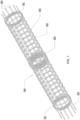
- the pile cage machine (100) comprises a linear welding unit (G) that cooperates with an operating unit (U) suitable for winding a wire spiral (80) outside an annular set of bars (90) along a helical trajectory, in such a way to realize a metal cage (99) suitable for being used as reinforcement for reinforced concrete piles.
- the operating unit (U) comprises a supporting and guiding base (1) for an opposite pair of identical heads (2 and 3), of which only one (3) is movable and slides along a direction (Y) parallel to the longitudinal axis of the base (1).
- the two heads house identical synchronously rotating disks (4 and 5), each one of them being equipped with an identical set of annular bushings, in a number equal to the bars (90) of the cage (99) to be made.
- said direction (Y) coincides with the axis of rotation of the rotating disks (4 and 5).
- the bushings (5a) situated in the disk (5) mounted on the movable head (3) are suitable for supporting and tightening the bar (90) that passes through them, whereas the bushings (4a) situated in the disk (4) mounted on the fixed head (2) are suitable for supporting and guiding the bar (90) that passes through them, allowing it to slide freely.
- the pile cage machine (100) comprises a handling and transporting unit (25) of said wire spiral (80), which is moved forward in a direction orthogonal to the sliding direction (Y) of said movable head (3), in such a way as to tangentially intersect the various bars (90) supported astride the two heads (2 and 3).
- Such a handling and transporting unit (25) of said wire spiral (80) is only partially shown in Fig. 3 , it being of known type, having a structural configuration and operating modes that are fully equivalent to those of the pile cage machines of the prior art that are equipped with a spot-welding unit.
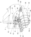
- the pile cage machine (100) also comprises a linear welding unit (G) that, in turn, comprises a welding torch (10) mounted on a carriage (19) articulatedly supported by a supporting frame (19a) that is fixed to the fixed head (2).
- a linear welding unit (G) that, in turn, comprises a welding torch (10) mounted on a carriage (19) articulatedly supported by a supporting frame (19a) that is fixed to the fixed head (2).
- the carriage (19) has several degrees of freedom and more precisely it can:
- said carriage (19) is not provided with autonomous motion, it being moved by the bar (90) that is intercepted from time to time by the wire spiral (80).
- Said carriage (19) is suitably equipped with a forked hook (40) that slides in the direction (A) shown in Fig. 4 , which is moved forward at the right moment to make the carriage (19) integral with the bar (90) in transit that is intercepted from time to time by the wire spiral (80).
- said carriage (19) comprises a pair of idle pulleys (20), whose grooves are permanently engaged with the outside of the wire spiral (80), in such a way that the direction assumed by the carriage (19) with respect to its supporting frame (19a) also depends on the angle of the helical winding trajectory of the wire spiral (80), that is to say on the pitch of said helical trajectory.
- the cage (99) is machined by rotating the rotating disk (4) in the direction indicated by the arrow (F1) in Fig. 2 .
- the rotating disk (5) is synchronized with the disk (4), in such a way that it is rotated in the same direction, as indicated by the arrow (F2) in Fig. 2 .
- the movable head (3) is moved away from the fixed head (2), thus determining the pitch of the helical winding trajectory of the wire spiral (80) around the annular set of bars (90).
- a proximity device (not shown in the figure) automatically acquires the position of the bars (90) and enables the intervention of said forked hook (40), which is moved forward along said direction (A) until it comes into contact with the bar (90).
- the welding torch (20) performs the welding between the bar (90) and the wire spiral (80).
- the position of the torch (90) relative to the bar (90) and to the wire spiral (80) that are being welded is determined by the forked hook (40) attached to the bar (90) and by the two pulleys (20) engaged with the wire spiral (80).
- the carriage (19) and the welding torch (10) are moved as indicated by the arrows (FX, FZ, FC, FB).
- said welding torch (10) is mounted on the carriage (19) by means of a set of levers (31, 32 and 33) operated by a motor (30), which impose independent simultaneous travels on the welding torch (10) with respect to the travels made by the carriage (19).
- said welding torch (10) is mounted on a first crank (32) that oscillates around an axis of rotation (O) and is coupled with a connecting rod (31), which is in turn coupled with a second crank (33) that oscillates around an axis of rotation (O') and is directly driven by said motor (30).
- a travel according to the arrow (FE) indicated in Fig. 4 can be imposed on the welding torch (10), during which said welding torch (10) performs a rotation around said axis (O), always remaining parallel to itself.
- the welding torch (10) can realize a welding seam (50) that extends along a section (90a) of the circumference (90b) of the bar (90), said section (90a) being disposed astride the tangential intersection point of the wire spiral (80) with the bar (90), as shown in Fig. 5 .
- the welding torch (10) is moved forward in opposite direction with respect to the carriage (19), which passively follows the roto-translation of the cage (99) that is being machined.
Landscapes
- Engineering & Computer Science (AREA)
- Mechanical Engineering (AREA)
- Physics & Mathematics (AREA)
- Plasma & Fusion (AREA)
- Optics & Photonics (AREA)
- Chemical & Material Sciences (AREA)
- Materials Engineering (AREA)
- Wire Processing (AREA)
Claims (6)
- Korbschweißmaschine (100) zur Herstellung eines Metallkorbes (99), umfassend eine ringförmige Reihe von Stäben (90), eine Drahtspirale (80), die entlang einer schraubenförmigen Bahn um die Stäbe (90) gewickelt und geschweißt wird; wobei die Maschine (100) umfasst:- eine Bedieneinheit (U), die dazu geeignet ist, die Drahtspirale (80) entlang einer schraubenförmigen Bahn über die Außenseite der ringförmigen Reihe von Stäben (90) zu wickeln, so dass der Metallkorb (99) hergestellt wird, wobei die Bedieneinheit (U) ein gegenüberliegendes Paar von Scheiben (4 und 5) umfasst, die synchron um eine Achse (Y) drehbar sind, die ringförmige Reihe von Stäben (90) stützen und ihnen sowohl eine Drehbewegung als auch eine Translationsbewegung relativ zur Achse (Y) auferlegen;- eine Handhabungs- und Transporteinheit (25) für die Drahtspirale (80), die in rechtwinkliger Richtung relativ zu der Drehachse (Y) vorwärtsbewegt wird, so dass sie die ringförmige Reihe von Stäben (90) tangential schneidet, bis die ringförmige Reihe von Stäben (90) von den sich drehenden Scheiben (4 und 5) in Drehung versetzt wird;- eine lineare Schweißeinheit (G), umfassend einen Schweißbrenner (10), der auf einem Schlitten (19) montiert ist, der mit einem Gabelhaken (40) versehen ist, um jeweils einen Stab (90) während der Drehung der sich drehenden Scheiben (4 und 5) zu befestigen, und mit einem Paar von losen Rollen (20) versehen ist, deren Nuten dauerhaft mit der Außenseite der Drahtspirale (80) in Eingriff stehen;wobei die Maschine (100) dadurch gekennzeichnet ist, dass der Schweißbrenner (10) auf dem Schlitten (19) unter Einfügung eines Satzes von Hebeln (31, 32 und 33) montiert ist, die von einem Motor (30) angetrieben werden und entsprechend konfiguriert sind, um dem Schweißbrenner gleichzeitige, eigenständige Bewegungen relativ zu dem Schlitten (19) aufzuerlegen, und entsprechend konfiguriert sind, um den Schweißbrenner (10) während der eigenständigen Bewegungen in paralleler Position zu sich selbst zu halten und während des Gebrauchs eine Schweißnaht (50) zu erzeugen, die sich über einen Abschnitt (90b) des Umfangs (90a) des Stabes (90) erstreckt, wobei der Abschnitt (90b) rittlings über dem tangentialen Schnittpunkt der Drahtspirale (80) mit dem Stab (90) angeordnet ist.
- Korbschweißmaschine (100) nach dem vorstehenden Anspruch, wobei der Schweißbrenner (10) auf einer ersten Kurbel (32) montiert ist, die um eine Drehachse (O) schwenkbar ist und mit einer Verbindungsstange (31) gekoppelt ist, die ihrerseits mit einer zweiten Kurbel (33) gekoppelt ist, die um eine Drehachse (O') schwenkbar ist und direkt von dem Motor (30) betätigt wird.
- Korbschweißmaschine (100) nach einem der vorstehenden Ansprüche, wobei der Schlitten (19) durch einen festen Rahmen (19a) gelenkig gelagert ist, wobei der Schlitten (19) in der Lage ist, relativ zu dem festen Rahmen (19a) folgende Bewegungen auszuführen:- alternierende Translationsbewegungen (FX) entlang einer Achse (X), die parallel zur Achse (Y) verläuft;- alternierende Translationsbewegungen (FZ) entlang einer Achse (Z), die rechtwinklig zur Achse (X) verläuft;- alternierende Drehbewegungen (FC) um die Achse (Z);- alternierende Translationsbewegungen (FB) entlang einer Achse (B), die senkrecht zu den beiden Achsen (X und Z) verläuft.
- Korbschweißmaschine (100) nach einem der vorstehenden Ansprüche, wobei die Bedieneinheit (U) einen Trag- und Führungssockel (1) für ein Paar von gegenüberliegenden, identischen Köpfen (2 und 3) umfasst, von denen nur ein Kopf (3) bewegbar ist und entlang einer Richtung parallel zur Achse (Y) gleitet; wobei die Köpfe (2 und 3) jeweils die sich synchron drehenden Scheiben (4 und 5) aufnehmen, wobei jede der Scheiben (4 und 5) mit einer identischen ringförmigen Reihe von Buchsen in der gleichen Anzahl wie die Stäbe (90) des herzustellenden Korbes (99) versehen ist.
- Korbschweißmaschine (100) nach dem vorstehenden Anspruch, wobei die Buchsen (5a), die in der Scheibe (5) angeordnet sind, die auf dem beweglichen Kopf (3) montiert ist, dazu geeignet sind, den Stab (90), der durch sie hindurchgeht, zu tragen und festzuziehen, während die Buchsen (4a), die in der Scheibe (4) angeordnet sind, die auf dem festen Kopf (2) montiert ist, dazu geeignet sind, den Stab (90), der durch sie hindurchgeht, zu tragen und zu führen, mit der Möglichkeit, frei zu gleiten.
- Schweißverfahren, implementiert mittels der Korbschweißmaschine (100) nach einem der vorstehenden Ansprüche und umfassend die folgenden Bedienschritte:- Wickeln einer Drahtspirale (80) entlang einer schraubenförmigen Bahn über die Außenseite einer ringförmigen Reihe von Stäben (90), wobei der ringförmigen Reihe von Stäben (90) eine gleichzeitige Drehbewegung relativ zu einer Drehachse (Y) sowie eine gleichzeitige Translationsbewegung entlang einer Richtung parallel zur Achse (Y) auferlegt wird;- Handhaben und Transportieren der Drahtspirale (80), die in rechtwinkliger Richtung relativ zu der Drehachse (Y) vorwärtsbewegt wird, so dass sie die ringförmige Reihe von Stäben (90) außen tangential schneidet;- Ausführen einer Schweißnaht (50), die sich über einen Abschnitt (90b) des Umfangs (90a) des Stabes (90) erstreckt, wobei der Abschnitt (90b) rittlings über dem tangentialen Schnittpunkt der Drahtspirale (80) mit dem Stab (90) angeordnet ist; wobei die Schweißnaht (50) mit einem Schweißbrenner (10) ausgeführt wird, der gelenkig auf einem Schlitten (19) unter Einfügung eines Satzes von Hebeln (31, 32 und 33) montiert ist, die von einem Motor (30) betätigt werden, der dem Schweißbrenner (10) eigenständige, gleichzeitige Bewegungen relativ zu dem Schlitten (19) auferlegt, wobei der Schweißbrenner (10) während der eigenständigen Bewegungen in paralleler Position zu sich selbst gehalten wird; wobei der Schlitten (19) mit einem Gabelhaken (40) versehen ist, um jeweils einen Stab (90) während der Bewegung der Stäbe (90) relativ zur Achse (Y) zu befestigen.
Applications Claiming Priority (1)
| Application Number | Priority Date | Filing Date | Title |
|---|---|---|---|
| IT202100001202 | 2021-01-22 |
Publications (3)
| Publication Number | Publication Date |
|---|---|
| EP4032634A1 EP4032634A1 (de) | 2022-07-27 |
| EP4032634C0 EP4032634C0 (de) | 2023-08-30 |
| EP4032634B1 true EP4032634B1 (de) | 2023-08-30 |
Family
ID=75340125
Family Applications (1)
| Application Number | Title | Priority Date | Filing Date |
|---|---|---|---|
| EP22151957.2A Active EP4032634B1 (de) | 2021-01-22 | 2022-01-18 | Pfahlkorbmaschine mit schweisseinheit |
Country Status (1)
| Country | Link |
|---|---|
| EP (1) | EP4032634B1 (de) |
Cited By (1)
| Publication number | Priority date | Publication date | Assignee | Title |
|---|---|---|---|---|
| IT202300023886A1 (it) | 2023-11-13 | 2025-05-13 | Emg Soc A Responsabilita Limitata | Gruppo di bloccaggio per una barra sottoposta a lavorazione. |
Families Citing this family (8)
| Publication number | Priority date | Publication date | Assignee | Title |
|---|---|---|---|---|
| CN115178930B (zh) * | 2022-08-04 | 2025-05-27 | 阜阳市节能化工工程有限公司 | 一种外滤式烟气除尘器配件自动生产设备 |
| CN115570301B (zh) * | 2022-10-25 | 2023-06-30 | 广东华亮建设有限公司 | 一种钢筋笼焊接设备 |
| CN116765661B (zh) * | 2023-06-30 | 2023-12-05 | 浙江新氟隆防腐设备有限公司 | 一种涂层用网格加强筋的焊接系统及其焊接方法 |
| CN116727975B (zh) * | 2023-07-12 | 2024-04-26 | 江苏江扬建材机械有限公司 | 一种滚焊机的焊臂调节机构 |
| CN116984414A (zh) * | 2023-09-20 | 2023-11-03 | 大连富地重工机械制造有限公司 | 一种自动钢丝上料装置 |
| CN117600360B (zh) * | 2024-01-24 | 2024-03-22 | 中铁四局集团有限公司 | 一种小型预制构件用半成品钢筋自动加工设备 |
| CN118989832B (zh) * | 2024-10-25 | 2025-01-24 | 四川爱买钢物联网科技有限公司 | 一种模块化钢筋笼搭接焊接定位机 |
| CN119609364B (zh) * | 2025-01-14 | 2025-09-26 | 江苏捷达交通工程集团有限公司 | 一种钢筋笼自动焊接用滚焊机 |
Family Cites Families (6)
| Publication number | Priority date | Publication date | Assignee | Title |
|---|---|---|---|---|
| JPH0771713B2 (ja) * | 1992-10-15 | 1995-08-02 | 平岡金属工業株式会社 | 鉄筋籠の溶接方法 |
| ITMC20080086A1 (it) * | 2008-05-22 | 2009-11-23 | Difer Impianti Srl | Dispositivo saldatore per gabbie metalliche. |
| ITAN20090007A1 (it) * | 2009-02-27 | 2010-08-28 | Carlo Leonardo Di | Unita' di saldatura. |
| IT1395677B1 (it) | 2009-05-28 | 2012-10-16 | Beta Systems S R L Con Unico Socio | Macchina per la realizzazione di gabbie di armatura, dispositivo di saldatura per la realizzazione delle gabbie e relativo procedimento di realizzazione |
| DE102018112925A1 (de) | 2018-05-30 | 2019-12-05 | Mbk Maschinenbau Gmbh | Korbschweißmaschine zur Herstellung eines Bewehrungskörpers |
| KR101970538B1 (ko) | 2018-10-12 | 2019-04-19 | 한국철강산업(주) | 양쪽 용접 방식을 적용한 원형 철근 케이지 제조방법 및 이를 위한 양쪽 용접 장치 |
-
2022
- 2022-01-18 EP EP22151957.2A patent/EP4032634B1/de active Active
Cited By (1)
| Publication number | Priority date | Publication date | Assignee | Title |
|---|---|---|---|---|
| IT202300023886A1 (it) | 2023-11-13 | 2025-05-13 | Emg Soc A Responsabilita Limitata | Gruppo di bloccaggio per una barra sottoposta a lavorazione. |
Also Published As
| Publication number | Publication date |
|---|---|
| EP4032634C0 (de) | 2023-08-30 |
| EP4032634A1 (de) | 2022-07-27 |
Similar Documents
| Publication | Publication Date | Title |
|---|---|---|
| EP4032634B1 (de) | Pfahlkorbmaschine mit schweisseinheit | |
| US10124433B2 (en) | Method and device for connecting the ends of steel tubes by means of orbital welding using a hybrid technique | |
| US5069382A (en) | Apparatus and method for producing a pressure vessel from metal tubing | |
| US20060070984A1 (en) | Feeder for endless welding wire | |
| RU2750878C1 (ru) | Машина для сварки каркаса для изготовления арматурного тела | |
| CN113070555B (zh) | 一种自动密封式管管焊接机头 | |
| WO2000045986A1 (en) | Method and device for welding together two bodies | |
| CN118989790A (zh) | 一种办公椅底座的变位式焊接设备 | |
| US20140021185A1 (en) | Method and system for the production of reinforcing dowel baskets for contracting-expanding joints | |
| KR20140144946A (ko) | 용접용 와이어 공급장치 | |
| JP2008114279A (ja) | アーク溶接装置 | |
| KR101707398B1 (ko) | 서브 머지드 용접 장치 | |
| JP6972250B1 (ja) | 溶接装置及び溶接方法 | |
| JP3600365B2 (ja) | 連続自動肉盛溶接装置 | |
| CN216462455U (zh) | 一种自动送丝激光焊接机 | |
| JP5083643B2 (ja) | 軸状部品をパイプ部材に溶接する溶接装置 | |
| US11684966B2 (en) | Device for producing a reinforcement | |
| CN214921410U (zh) | 一种电感辅助脉冲激光摆动焊接装置 | |
| KR102119629B1 (ko) | 머플러 행거 앗세이 조립 시스템 | |
| JP3946570B2 (ja) | Tig溶接装置及びtig溶接方法 | |
| JPH04371337A (ja) | チェーンの製造方法 | |
| KR101546181B1 (ko) | 용접 장치 | |
| KR20250005045A (ko) | 적층 철심과 그 제조 장치 및 제조 방법 | |
| CN221621080U (zh) | 具有弯曲面的板材自动焊接机用连接装置 | |
| JP7238221B2 (ja) | アークスポット溶接装置 |
Legal Events
| Date | Code | Title | Description |
|---|---|---|---|
| PUAI | Public reference made under article 153(3) epc to a published international application that has entered the european phase |
Free format text: ORIGINAL CODE: 0009012 |
|
| STAA | Information on the status of an ep patent application or granted ep patent |
Free format text: STATUS: THE APPLICATION HAS BEEN PUBLISHED |
|
| AK | Designated contracting states |
Kind code of ref document: A1 Designated state(s): AL AT BE BG CH CY CZ DE DK EE ES FI FR GB GR HR HU IE IS IT LI LT LU LV MC MK MT NL NO PL PT RO RS SE SI SK SM TR |
|
| STAA | Information on the status of an ep patent application or granted ep patent |
Free format text: STATUS: REQUEST FOR EXAMINATION WAS MADE |
|
| 17P | Request for examination filed |
Effective date: 20221010 |
|
| RBV | Designated contracting states (corrected) |
Designated state(s): AL AT BE BG CH CY CZ DE DK EE ES FI FR GB GR HR HU IE IS IT LI LT LU LV MC MK MT NL NO PL PT RO RS SE SI SK SM TR |
|
| RIC1 | Information provided on ipc code assigned before grant |
Ipc: B23K 37/02 20060101ALI20230302BHEP Ipc: B21F 27/12 20060101AFI20230302BHEP |
|
| GRAP | Despatch of communication of intention to grant a patent |
Free format text: ORIGINAL CODE: EPIDOSNIGR1 |
|
| STAA | Information on the status of an ep patent application or granted ep patent |
Free format text: STATUS: GRANT OF PATENT IS INTENDED |
|
| INTG | Intention to grant announced |
Effective date: 20230412 |
|
| GRAS | Grant fee paid |
Free format text: ORIGINAL CODE: EPIDOSNIGR3 |
|
| GRAA | (expected) grant |
Free format text: ORIGINAL CODE: 0009210 |
|
| STAA | Information on the status of an ep patent application or granted ep patent |
Free format text: STATUS: THE PATENT HAS BEEN GRANTED |
|
| AK | Designated contracting states |
Kind code of ref document: B1 Designated state(s): AL AT BE BG CH CY CZ DE DK EE ES FI FR GB GR HR HU IE IS IT LI LT LU LV MC MK MT NL NO PL PT RO RS SE SI SK SM TR |
|
| REG | Reference to a national code |
Ref country code: GB Ref legal event code: FG4D |
|
| REG | Reference to a national code |
Ref country code: CH Ref legal event code: EP |
|
| REG | Reference to a national code |
Ref country code: DE Ref legal event code: R096 Ref document number: 602022000388 Country of ref document: DE |
|
| REG | Reference to a national code |
Ref country code: IE Ref legal event code: FG4D |
|
| U01 | Request for unitary effect filed |
Effective date: 20230928 |
|
| U07 | Unitary effect registered |
Designated state(s): AT BE BG DE DK EE FI FR IT LT LU LV MT NL PT SE SI Effective date: 20231006 |
|
| PG25 | Lapsed in a contracting state [announced via postgrant information from national office to epo] |
Ref country code: GR Free format text: LAPSE BECAUSE OF FAILURE TO SUBMIT A TRANSLATION OF THE DESCRIPTION OR TO PAY THE FEE WITHIN THE PRESCRIBED TIME-LIMIT Effective date: 20231201 |
|
| PG25 | Lapsed in a contracting state [announced via postgrant information from national office to epo] |
Ref country code: IS Free format text: LAPSE BECAUSE OF FAILURE TO SUBMIT A TRANSLATION OF THE DESCRIPTION OR TO PAY THE FEE WITHIN THE PRESCRIBED TIME-LIMIT Effective date: 20231230 |
|
| U20 | Renewal fee for the european patent with unitary effect paid |
Year of fee payment: 3 Effective date: 20231221 |
|
| PG25 | Lapsed in a contracting state [announced via postgrant information from national office to epo] |
Ref country code: RS Free format text: LAPSE BECAUSE OF FAILURE TO SUBMIT A TRANSLATION OF THE DESCRIPTION OR TO PAY THE FEE WITHIN THE PRESCRIBED TIME-LIMIT Effective date: 20230830 Ref country code: NO Free format text: LAPSE BECAUSE OF FAILURE TO SUBMIT A TRANSLATION OF THE DESCRIPTION OR TO PAY THE FEE WITHIN THE PRESCRIBED TIME-LIMIT Effective date: 20231130 Ref country code: IS Free format text: LAPSE BECAUSE OF FAILURE TO SUBMIT A TRANSLATION OF THE DESCRIPTION OR TO PAY THE FEE WITHIN THE PRESCRIBED TIME-LIMIT Effective date: 20231230 Ref country code: HR Free format text: LAPSE BECAUSE OF FAILURE TO SUBMIT A TRANSLATION OF THE DESCRIPTION OR TO PAY THE FEE WITHIN THE PRESCRIBED TIME-LIMIT Effective date: 20230830 Ref country code: GR Free format text: LAPSE BECAUSE OF FAILURE TO SUBMIT A TRANSLATION OF THE DESCRIPTION OR TO PAY THE FEE WITHIN THE PRESCRIBED TIME-LIMIT Effective date: 20231201 |
|
| PG25 | Lapsed in a contracting state [announced via postgrant information from national office to epo] |
Ref country code: PL Free format text: LAPSE BECAUSE OF FAILURE TO SUBMIT A TRANSLATION OF THE DESCRIPTION OR TO PAY THE FEE WITHIN THE PRESCRIBED TIME-LIMIT Effective date: 20230830 |
|
| PG25 | Lapsed in a contracting state [announced via postgrant information from national office to epo] |
Ref country code: ES Free format text: LAPSE BECAUSE OF FAILURE TO SUBMIT A TRANSLATION OF THE DESCRIPTION OR TO PAY THE FEE WITHIN THE PRESCRIBED TIME-LIMIT Effective date: 20230830 |
|
| PG25 | Lapsed in a contracting state [announced via postgrant information from national office to epo] |
Ref country code: SM Free format text: LAPSE BECAUSE OF FAILURE TO SUBMIT A TRANSLATION OF THE DESCRIPTION OR TO PAY THE FEE WITHIN THE PRESCRIBED TIME-LIMIT Effective date: 20230830 Ref country code: RO Free format text: LAPSE BECAUSE OF FAILURE TO SUBMIT A TRANSLATION OF THE DESCRIPTION OR TO PAY THE FEE WITHIN THE PRESCRIBED TIME-LIMIT Effective date: 20230830 Ref country code: ES Free format text: LAPSE BECAUSE OF FAILURE TO SUBMIT A TRANSLATION OF THE DESCRIPTION OR TO PAY THE FEE WITHIN THE PRESCRIBED TIME-LIMIT Effective date: 20230830 Ref country code: CZ Free format text: LAPSE BECAUSE OF FAILURE TO SUBMIT A TRANSLATION OF THE DESCRIPTION OR TO PAY THE FEE WITHIN THE PRESCRIBED TIME-LIMIT Effective date: 20230830 Ref country code: SK Free format text: LAPSE BECAUSE OF FAILURE TO SUBMIT A TRANSLATION OF THE DESCRIPTION OR TO PAY THE FEE WITHIN THE PRESCRIBED TIME-LIMIT Effective date: 20230830 |
|
| REG | Reference to a national code |
Ref country code: DE Ref legal event code: R097 Ref document number: 602022000388 Country of ref document: DE |
|
| PLBE | No opposition filed within time limit |
Free format text: ORIGINAL CODE: 0009261 |
|
| STAA | Information on the status of an ep patent application or granted ep patent |
Free format text: STATUS: NO OPPOSITION FILED WITHIN TIME LIMIT |
|
| 26N | No opposition filed |
Effective date: 20240603 |
|
| PG25 | Lapsed in a contracting state [announced via postgrant information from national office to epo] |
Ref country code: MC Free format text: LAPSE BECAUSE OF FAILURE TO SUBMIT A TRANSLATION OF THE DESCRIPTION OR TO PAY THE FEE WITHIN THE PRESCRIBED TIME-LIMIT Effective date: 20230830 |
|
| PG25 | Lapsed in a contracting state [announced via postgrant information from national office to epo] |
Ref country code: MC Free format text: LAPSE BECAUSE OF FAILURE TO SUBMIT A TRANSLATION OF THE DESCRIPTION OR TO PAY THE FEE WITHIN THE PRESCRIBED TIME-LIMIT Effective date: 20230830 |
|
| PG25 | Lapsed in a contracting state [announced via postgrant information from national office to epo] |
Ref country code: IE Free format text: LAPSE BECAUSE OF NON-PAYMENT OF DUE FEES Effective date: 20240118 |
|
| PG25 | Lapsed in a contracting state [announced via postgrant information from national office to epo] |
Ref country code: IE Free format text: LAPSE BECAUSE OF NON-PAYMENT OF DUE FEES Effective date: 20240118 |
|
| U20 | Renewal fee for the european patent with unitary effect paid |
Year of fee payment: 4 Effective date: 20250102 |
|
| PG25 | Lapsed in a contracting state [announced via postgrant information from national office to epo] |
Ref country code: CY Free format text: LAPSE BECAUSE OF FAILURE TO SUBMIT A TRANSLATION OF THE DESCRIPTION OR TO PAY THE FEE WITHIN THE PRESCRIBED TIME-LIMIT; INVALID AB INITIO Effective date: 20220118 |
|
| REG | Reference to a national code |
Ref country code: CH Ref legal event code: PL |
|
| PG25 | Lapsed in a contracting state [announced via postgrant information from national office to epo] |
Ref country code: CH Free format text: LAPSE BECAUSE OF NON-PAYMENT OF DUE FEES Effective date: 20250131 |
|
| PG25 | Lapsed in a contracting state [announced via postgrant information from national office to epo] |
Ref country code: TR Free format text: LAPSE BECAUSE OF FAILURE TO SUBMIT A TRANSLATION OF THE DESCRIPTION OR TO PAY THE FEE WITHIN THE PRESCRIBED TIME-LIMIT Effective date: 20230830 |
|
| U20 | Renewal fee for the european patent with unitary effect paid |
Year of fee payment: 5 Effective date: 20251110 |