EP4032014B1 - Aufbau zur umhüllung von etiketten und verfahren zur anbringung eines etiketts an ein kabel - Google Patents
Aufbau zur umhüllung von etiketten und verfahren zur anbringung eines etiketts an ein kabel Download PDFInfo
- Publication number
- EP4032014B1 EP4032014B1 EP20865285.9A EP20865285A EP4032014B1 EP 4032014 B1 EP4032014 B1 EP 4032014B1 EP 20865285 A EP20865285 A EP 20865285A EP 4032014 B1 EP4032014 B1 EP 4032014B1
- Authority
- EP
- European Patent Office
- Prior art keywords
- label
- wire
- resilient members
- resilient
- resilient member
- Prior art date
- Legal status (The legal status is an assumption and is not a legal conclusion. Google has not performed a legal analysis and makes no representation as to the accuracy of the status listed.)
- Active
Links
Images


Classifications
-
- B—PERFORMING OPERATIONS; TRANSPORTING
- B65—CONVEYING; PACKING; STORING; HANDLING THIN OR FILAMENTARY MATERIAL
- B65C—LABELLING OR TAGGING MACHINES, APPARATUS, OR PROCESSES
- B65C3/00—Labelling other than flat surfaces
- B65C3/02—Affixing labels to elongated objects, e.g. wires, cables, bars, tubes
-
- B—PERFORMING OPERATIONS; TRANSPORTING
- B65—CONVEYING; PACKING; STORING; HANDLING THIN OR FILAMENTARY MATERIAL
- B65C—LABELLING OR TAGGING MACHINES, APPARATUS, OR PROCESSES
- B65C9/00—Details of labelling machines or apparatus
- B65C9/08—Label feeding
- B65C9/18—Label feeding from strips, e.g. from rolls
-
- B—PERFORMING OPERATIONS; TRANSPORTING
- B65—CONVEYING; PACKING; STORING; HANDLING THIN OR FILAMENTARY MATERIAL
- B65C—LABELLING OR TAGGING MACHINES, APPARATUS, OR PROCESSES
- B65C9/00—Details of labelling machines or apparatus
- B65C9/26—Devices for applying labels
- B65C9/36—Wipers; Pressers
-
- B—PERFORMING OPERATIONS; TRANSPORTING
- B65—CONVEYING; PACKING; STORING; HANDLING THIN OR FILAMENTARY MATERIAL
- B65C—LABELLING OR TAGGING MACHINES, APPARATUS, OR PROCESSES
- B65C9/00—Details of labelling machines or apparatus
- B65C9/46—Applying date marks, code marks, or the like, to the label during labelling
Definitions
- This invention relates to an assembly for a label wrapper and a related method of attaching a label to a wire.
- An assembly comprising the features of the preamble of claim 1 is known from US 2002/084020 A1 .
- Thermal transfer label printers are often used for printing various labels.
- a label and a thermal transfer printer ribbon are compressed between a print head and a roller and fed together past the print head. The print head produces sufficient heat in the appropriate locations to transfer the ink from the ribbon to the label to print a label.
- the labels produced by the printer are often then applied to the wires being labeled by hand.
- industry or customer specifications may dictate a type of label that can be applied.
- the label may be a heat-shrink tubing label, a material configured to wrap around an object, a self-laminating label, a flag label, and/or a non-adhesive label. Applying a label to a wire by hand has many drawbacks.
- Label application mechanisms are available that automatically apply tape and preprinted labels to cylindrical objects, such as bottles, cans, and the like. These systems typically require the object being labeled to be conveyed past the applicator mechanism in order for the mechanism to apply a preprinted label. A finishing device can then press the label to the object.
- these systems are designed to be used with large diameter cylindrical objects such as cans or bottles and none of these systems can be used or be easily adapted to be used with elongated, flexible objects of a small diameter such as wires, wire bundles, and non-cylindrical objects. Additionally, label application mechanisms are usually very large and adjustments take a significant amount of time.
- a flag label onto a cylindrical object having a relatively small diameter such as a wire
- the label can stick to the label applicator as it is pressed against the object or the label may be misaligned.
- JP 2011 246162 A discloses a pollination date marker which attaches a tag for identifying a pollination date of a plant to a vine, branch or stalk of the plant by simple operations.
- the pollination date marker includes a presser and a tag.
- an assembly for a label wrapper having a support structure defining a receiving space.
- the receiving space includes opposing sidewalls and a bottom wall.
- First and second resilient members are positioned on two opposing sides of the receiving space.
- the first and second resilient members are at least partially vertically aligned with one another.
- Third and fourth resilient members are respectively positioned between the first and second resilient members and the bottom wall.
- the third and fourth resilient members are also at least partially vertically aligned with one another.
- a first flexible sheet is disposed over the first resilient member and along a side portion of the third resilient member.
- a second flexible sheet is disposed over the second resilient member and along a side portion of the fourth resilient member.
- the first and second flexible sheets are configured to support a label having an adhesive material on a first side thereof and the first and second resilient members are configured to press a first segment of the first side of the label against a second segment of the first side of the label after the label at least partially surrounds an elongated object.
- the assembly also includes a fifth resilient member positioned between the third resilient member and the bottom wall and a sixth resilient member positioned between the fourth resilient member and the bottom wall.
- the fifth and sixth resilient members are at least partially vertically aligned with one another on opposing sides of the receiving space.
- the support structure includes first and second brackets each including a first portion and an offset second portion.
- the first bracket is operably coupled with the first and third resilient members and the second bracket is operably coupled with the second and fourth resilient members.
- the assembly also includes a first brace positioned on an opposing side of the first bracket from the first or third resilient member and a second brace positioned on an opposing side of the second bracket from the second or fourth resilient member.
- a bottom portion of the first brace includes a locator projecting therefrom that is configured to interact with a locating hole defined by a bottom portion of the second brace.
- a first hem is retained by a tab on the first bracket and a second hem positioned within a void defined by the first bracket.
- the first hem is configured to selectively retain a first end portion of the first flexible sheet.
- the second hem is configured to selectively retain a second, opposing end portion of the first flexible sheet.
- a middle portion of the first flexible sheet is wrapped about a retaining pin.
- the retaining pin allows the first flexible sheet to be a single sheet that extends over a top portion and a bottom portion of the first resilient member, around the retaining pin, along a top portion of the third resilient member, and along a side portion of the fifth resilient member.
- the third and fourth resilient members each define a chamfered edge.
- the first and second resilient members are formed from a first material having a first density and the fifth and sixth members are formed from a second material having a second density.
- the second density is greater than the first density.
- a method of attaching a label to a wire that includes positioning said label above first and second abutting resilient members.
- the label has an adhesive material on a first side thereof.
- the method also includes positioning the wire on an opposing side of the label from the first and second resilient members.
- the method further includes sliding the wire between the first and second resilient members.
- the first and second resilient members press a first segment of the first side of the label against a second segment of the first side of the label.
- the method includes rotating the first and second resilient members relative to the wire.
- the method may further include the step of sliding the wire between third and fourth resilient members.
- the sliding the wire between the first and second resilient members step includes positioning the wire between first and second flexible sheets.
- the first flexible sheet extends between the label and the first resilient member and the second flexible sheet extends between the label and the second resilient member.
- the rotating the first and second resilient members relative to the wire step includes rotating the first and second resilient members in a first direction relative to the wire followed by a rotation in a second, opposing direction.
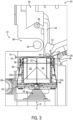
- a label applicator 10 includes a printer 12 and a label wrapper 14 mounted on a base assembly 16.
- a controller electrically connected to both the printer 12 and the label wrapper 14 integrates the operation of the printer 12 and label wrapper 14 to print a label and wrap the printed label onto an elongated object, such as a wire.
- the controller includes any combination of software and/or processing circuitry suitable for controlling various components of the label applicator 10 described herein including without limitation processors, microcontrollers, application-specific integrated circuits, programmable gate arrays, and any other digital and/or analog components, as well as combinations of the foregoing, along with inputs and outputs for transceiving control signals, drive signals, power signals, sensor signals, and so forth. All such computing devices and environments are intended to fall within the meaning of the term "controller” or "processor” as used herein unless a different meaning is explicitly provided or otherwise clear from the context.
- the base assembly 16 provides support and stability for the label applicator 10, and can slidably mount the printer 12 relative to the label wrapper 14.
- the base assembly 16 includes a base 18 having a top wall 20 supported by a pair of longitudinal legs 22.
- the top wall 20 and legs 22 are formed from a single sheet of a rigid material, such as steel, aluminum, plastic, and the like.
- a base 18 may be formed from a single sheet of material, the base 18 can be assembled from one or more components secured together by screws, bolts and nuts, welding, adhesives, and so on.
- the printer 12 is configured to print indicia onto label 24 and dispenses the printed label 24 into the label wrapper 14.
- the printer 12 is a thermal transfer printer having an upper assembly pivotally fixed to a lower assembly.
- the printer 12 can be any printer known in the art, such as an ink jet printer, laser printer, impact printer, and the like.
- the printer 12 includes a print head assembly 26 that prints indicia onto the label 24.
- a peel plate 28 is mounted forward of a platen roller and defines a dispensing edge. The dispensing edge forms a corner for peeling the label 24 from the substrate once the printing is complete.
- the peel plate 28 with the dispensing edge can ensure consistent dispensing of the label 24 with minimal tension on the substrate to eliminate feed problems caused by excessive substrate tension.
- a label deflector 30 guides the label 24 detaching from the substrate into the label wrapper 14 and is rotatably supported between a pair of end brackets 32 above the peel plate 28.
- the label deflector 30 deflects the label 24 to prevent the label 24 from reattaching onto the substrate and to ensure that the label 24 is dispensed in a generally predefined position within the label wrapper 14.
- a striker 34 is mounted within the label wrapper 14.
- the striker 34 contacts a striker roller 36 forming part of the label wrapper 14.
- the striker 34 urges the striker roller 36 downwardly which clears an opening 38 from an attachment assembly 48 for insertion of a wire 40 being wrapped with the label 24.
- a locking assembly 42 ( FIG. 2 ) may clamp onto the wire 40 being wrapped to tension the wire 40.
- the striker roller 36 is contacted by the striker 34 to move a slider 44 in a vertical direction against the urging of a spring 46 away from the opening 38 to provide space for inserting a wire 40 into the opening 38.
- the spring 46 urges the attachment assembly 48 upwardly along an extension axis A to place the wire 40 within the attachment assembly 48.
- any biasing mechanism can be used, such as an elastomeric material, leaf spring, a motor, a pneumatic device, or the like. Additional information regarding the various components of a label applicator 10 is disclosed in U.S. Patent No. 7,178,572 to Schanke et al., entitled "LABEL WRAPPER BLOCK ASSEMBLY," issued Feb. 20, 2007 , the entire disclosure of which is incorporated herein by reference.
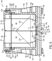
- the attachment assembly 48 is coupled to the slider 44 and biased upwardly toward the striker 34.
- the attachment assembly 48 includes a support structure 50 that defines a receiving space 52.
- the receiving space 52 is defined by opposing sidewalls 54a, 54b and a bottom wall 56.
- First and second resilient members 58, 60 are positioned on two opposing sides of the receiving space 52.
- Third and fourth resilient members 62, 64 are respectively positioned between the first and second resilient members 58, 60 and the bottom wall 56.
- fifth and sixth resilient members 66, 68 may be respectively positioned between the third and fourth resilient members 62, 64 and the bottom wall 56.
- a first flexible sheet 70 is disposed over the first resilient member 58 and along a side portion of the third resilient member 62.
- a second flexible sheet 72 is disposed over the second resilient member 60 and along a side portion of the fourth resilient member 64.
- the first and second sheets 70, 72 in conjunction with the resilient members 58, 60, 62, 64, 66, 68, apply pressure to a wire 40 and a label 24 that is inserted into the attachment assembly 48 for attaching the label 24 to the wire 40 and/or to itself.
- the first and second flexible sheets 70, 72 can serve as a low-friction surface onto which the label 24 may be placed.
- the flexible sheets may also reduce friction between the attachment assembly 48 and the wire 40 / label 24 when the attachment assembly 48 is linearly and/or rotationally moving relative to the wire 40, which may improve the end quality of the attached label 24. Additionally, the flexible sheets 70, 72 may protect the resilient members 58, 60, 62, 64, 66, 68 from wear and tear.
- the label 24 is positioned on the first and/or second sheets 70, 72.
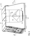
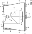
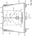
- the label 24 is configured to fold around the wire 40 and have first and second opposing end segments 74, 76 that couple with one another remotely from the wire 40 thereby forming a flag label 24 when the attachment assembly 48 is moved from a first position in which the wire 40 is separated from the attachment assembly 48, as generally illustrated in FIG. 3 , to a second position in which the wire 40 is disposed within a receiving space 52 defined by the attachment assembly 48, as generally illustrated in FIG. 10 .
- the support structure 50 of the attachment assembly 48 can include one or more braces 78, 80 and/or brackets 82, 84.
- the support structure 50 includes a support plate 86.
- the first and second braces 78, 80 are releasably fixed to the support plate 86 through one or more fasteners 88 positioned through fastener holes within the support plate 86 and inserted into the first and second braces 78, 80.
- the support plate 86 may also support a spring rod 90 for operably coupling with the spring 46.
- first and second braces 78, 80 each include a side portion 92 and an offset bottom portion 94.
- Each side portion 92 can include a rib structure 96 and one or more retainment tabs 98.
- the rib structure 96 and/or the retainment tabs 98 may be integrally formed with various other portions of the first and second braces 78, 80 or later attached thereto.
- the first and second braces 78, 80 may be formed from a polymeric and/or elastomeric material. However, any other practicable material may be used in conjunction with or in lieu of the polymeric or elastomeric material.
- locators 100 and/or voids 102 may be formed within the first and second braces 78, 80.
- the first and second braces 78, 80 may be in an aligned relationship.
- the first and second braces 78, 80 may also form alignment protrusions 104 that can be positioned within alignment spaces 102 defined by the support plate 86.
- the first and second braces 78, 80 can be attached to the support plate 86 through the usage of the one or more fasteners 88. It will be appreciated that the support structure 50 may include any number of braces 78, 80 having any alignment assemblies.
- the first and second braces 78, 80 may define the receiving space 52.
- the bottom portion 94 of the first and second braces 78, 80 may include a base section 108.
- First and second lateral walls 110, 112 extend from each base section 108.
- a connecting wall 114 couples the first and second lateral walls 110, 112 and likewise extend outwardly from the base section 108 of each of the first and second braces 78, 80.
- the first and second brackets 82, 84 may be positioned within the receiving space 52 defined by the support structure 50.
- the first and second brackets 82, 84 each include a first portion 116 and an offset second portion 118.
- the first and second lateral walls 110, 112, along with the connecting walls 114, of the first and second braces 78, 80 may respectively extend further inwardly than the first portion 116 of the first and second brackets 82, 84. Accordingly, the first portion 116 of the first and second brackets 82, 84 may be housed, or have their perimeters surrounded by the first and second braces 78, 80.
- the first resilient member 58 extends into the receiving space 52 from the first portion 116 of the first bracket 82.
- the second resilient member 60 extends into the receiving space 52 from the first portion 116 of the second bracket 84.
- the first and second resilient members 58, 60 may be retained in an at least partially vertically aligned position. As used herein, any two components that are "at least partially vertically aligned" both intersect a common plane that is perpendicular to the actuation axis A of the attachment assembly 48.
- the third resilient member 62 may extend from the first bracket 82 in an at least partially vertically aligned position with the fourth resilient member 64, which can extend inwardly of the second bracket 84.
- a fifth resilient member 66 may extend inwardly from the first bracket 82 and/or be supported by the second portion 118 of the first bracket 82.
- a sixth resilient member 68 may extend inwardly from the second bracket 84 and/or be supported by the second portion 118 of the second bracket 84.
- the first and second resilient members 58, 60 may have a substantially rectangular cross section.
- the second and third resilient members 62, 64 may each include a chamfered surface 120 on an inward portion.
- the fifth resilient member 66 may be positioned on an opposing side of the third resilient member 62 from the first resilient member 58 and may extend along the second portion 118 of the first bracket 82.
- the sixth resilient member 68 may be positioned on an opposing side of the fourth resilient member 64 from the second resilient member 60 and may extend along the second portion 118 of the second bracket 84.
- the fifth and sixth resilient members 66, 68 may extend further inwardly, or towards one another, than the second portions 118 of the first and/or second brackets 82, 84.
- a first channel 122 may be defined between the first and second resilient members 58, 60.
- a second channel 124 may be formed between the third and fourth resilient members 62, 64 and terminate at the chamfered surfaces 120.
- a third channel 126 may be defined between the fifth and sixth resilient members 66, 68.
- a cavity 128 may be bounded by the chamfered surfaces 120 of the third and fourth resilient members 62, 64 and the top surfaces of the fifth and sixth resilient members 66, 68.
- the wire 40 As a wire 40 is inserted into the attachment assembly 48, the wire 40 initially passes through the first channel 122. Next, as the attachment assembly 48 continues to move along the extension axis A ( FIG. 3 ), the wire 40 may be disposed within the second channel 124. After the second channel 124, the wire 40 continues to be positioned within the cavity 128. Next, in instances when the wire 40 has a diameter that is below a predefined diameter, the wire 40 enters into the third channel 126. However, when the wire 40 has a diameter that is greater than the predefined diameter, the wire 40 is maintained in the cavity 128.
- Each of the six resilient members 58, 60, 62, 64, 66, 68 may be formed from any practicable material capable of elastic deformation.
- each of the six resilient members 58, 60, 62, 64, 66, 68 may be at least partially formed from an open or closed cell foam material. This material may be elastically compressible and rebound towards and to its original shape.
- the first and second resilient members 58, 60 may be formed of a first material having a first density.
- the third and fourth resilient members 62, 64 may be formed of a second material having a second density.
- the fifth and sixth resilient members 66, 68 may be formed of a material having a third density.
- the first and second densities may be substantially similar and lower than the third density.
- one or more of the six resilient members 58, 60, 62, 64, 66, 68 may have a flexible shell that retains a fluid therein.
- the first, second, third, and fourth resilient members 58, 60, 62, 64 may have a fluid with a lower viscosity than the fifth and sixth resilient members 66, 68.
- Each of the six resilient members 58, 60, 62, 64, 66, 68 may be retained in a defined position through the usage of an adhesive material and/or through the usage of one or more fasteners.
- one or more of the six resilient members 58, 60, 62, 64, 66, 68 may be selectively retained by the first or second sheet 70, 72 or integrally formed with any component of the attachment assembly 48 for maintaining the resilient members 58, 60, 62, 64, 66, 68 in a desired position.
- the first flexible sheet 70 may have a first end portion 130 retained within a first hem 132 and a second end portion 134 retained in a second hem 136.
- the first hem 132 may be positioned on an opposing side of the first brace 78 from the first resilient member 58 and retained against the first brace 78 by the retainment tabs 98.
- the retainment tabs 98 may each include an elongated arm 138 and retainment feature 140, such as a lip, for maintaining the first hem 132 in a predefined position.
- the second hem 136 may be positioned on an opposing side of the first brace 78 from the fifth resilient member 66 and within a void 142 defined by the first and second braces 78, 80.
- the first flexible sheet 70 may be routed along various portions of the first flexible sheet 70 and may extend from the first hem 132 over a top portion of the first brace 78 and a top portion of the first resilient member 58. The first flexible sheet 70 may then extend through the first channel 122 and between the first and third resilient members 58, 62 and/or along a bottom portion of the first resilient member 58.
- a retaining pin 144 may maintain an intermediate portion 146 of the first flexible sheet 70 between the first and second end portions 130, 134.
- the retaining pin 144 is positioned on an opposing side of the first bracket 82 from the first resilient member 58.
- the first flexible sheet 70 is positioned through a hole 148 defined by the first bracket 82 (see e.g., FIG. 5 ), wrapped around the retaining pin 144, and returns through the hole 148.
- the hole 148 may include an upper portion 150 having a first width and a lower portion 152 having a second width that is less than the first width.
- the first flexible sheet 70 may then extend from the retaining pin 144 to a position over a top portion and along an interior side of the third resilient member 62. Next, the first flexible sheet 70 may extend along a side portion of the fifth resilient member 58, through a gap 154 between the first and second brackets 82, 84 and in into the void 142 defined by the first brace 78. In some examples, the second hem 136 may be retained in compression between the first brace 78 and the first bracket 82.
- the second flexible sheet 72 may have a first end portion 156 retained within a third hem 158 and a second end portion 160 retained in a fourth hem 162.
- the third hem 158 may be positioned on an opposing side of the second brace 80 from the second resilient member 60 and retained against the second brace 80 by the retainment tabs 98.
- the fourth hem 162 may be positioned on an opposing side of the second brace 80 from the sixth resilient member 68 and within the void 142 defined by the first and second braces 78, 80.
- the first, second, third, and fourth hems 132, 136, 158, 162 may each be formed as any type of fastening device.
- the hems may be configured as a metallic component that compressively retains the first or second sheet 70, 72. Additionally or alternatively, the hems may be configured as a threaded connection between the fabric and the support structure 50 and/or any other fastening device.
- the second flexible sheet 72 may extend from the third hem 158 over a top portion of the second brace 80 and a top portion of the second resilient member 60.
- the second flexible sheet 72 may then extend through the first channel 122 and between the second and fourth resilient members 60, 64 and/or along a bottom portion of the second resilient member 60.
- a retaining pin 144 is positioned on an opposing side of the second bracket 84 from the second resilient member 60.
- the second flexible sheet 72 is positioned through a hole 148 defined by the second bracket 84, wrapped around the retaining pin 144, and returns through the hole 148.
- the hole 148 may include an upper portion 150 having a first width and a lower portion 152 having a second width that is less than the first width.
- the second flexible sheet 72 may then extend from the retaining pin 144 to a position over a top portion and along an interior side of the fourth resilient member 64. Next, the second flexible sheet 72 may extend along a side portion of the sixth resilient member 68, through the gap 154 between the first and second brackets 82, 84 and in into the void 142 defined by the first and second braces 78, 80. In some examples, the fourth hem 162 may be retained in compression between the second brace 80 and the second bracket 84.
- the first and second sheets 70, 72 may each be comprised of or include a non-stick fabric, such as a Teflon coated or impregnated fibers, silicon coated or impregnated fabric, and the like, which provides a non-stick surface.
- a method 164 for placing a flag label 24 on a wire 40 can begin at step 166, where a wire 40 is positioned within an opening 38 of a label wrapper 14.
- a fixing device is actuated to retain the wire 40 in a predefined position.
- the printer 12 prints the label 24 and dispenses the label 24 onto the first and second flexible sheets 70, 72, as illustrated in FIG. 8 .
- the label 24 can be dispensed such that a surface of the label 24 having an adhesive material 172 thereon faces the wire 40.
- the controller sends a signal to move the striker 34 upwards from a first position to a second position.
- the attachment assembly 48 also moves upward due to the force of the spring 46 ( FIG. 3 ) such that the wire 40 is inserted into the first channel 122, at step 176, as generally illustrated in FIG. 9 .
- first and second resilient members 66, 68 in conjunction with the first and second sheets 70, 72, may press against the label 24 causing the label 24 to at least partially surround the wire 40.
- first and second resilient members 58, 60 in conjunction with the first and second sheets 70, 72, press a first segment 74 of the first side of the label 24 against a second segment 76 of the first side of the label 24 thereby forming a flag extending from the wire 40.
- the wire 40 and the label 24 enter the second channel 124.
- the wire 40 and the label 24 are positioned within the cavity 128 defined by the third, fourth, fifth, and sixth resilient members 62, 64, 66, 68. While the wire 40 is positioned within the cavity 128, the first and second flexible sheets 70, 72 apply pressure to the label 24 and the wire 40 to further adhere the label 24 to the wire 40 and adhere the first and second segments 74, 76 of the label 24 to one another.
- the first and second flexible sheets 70, 72 may provide a substantially uniform pressure on the label 24 being applied to the wire 40 regardless of the size of the wire 40 and the label 24.
- the wire 40 may continue into the third channel 126.
- the fifth and sixth resilient members 66, 68 may be formed from a material having a higher density than the remaining resilient members 58, 60, 62, 64 such that the fifth and sixth resilient members 66, 68 may apply more pressure to the label 24 and wire 40 than the first and second resilient members 58, 60.
- the attachment assembly 48 may rotate relative to the wire 40 to further adhere the label 24 to the wire 40.
- the attachment assembly 48 may rotate in a first direction about the axis of the wire, followed by a rotation in a second, opposing direction. In some instances, the first and second rotations may be between 120 and 240 degrees.
- the striker 34 may reengage the slider 44, which in turn, presses the attachment assembly 48 away from the wire 40 at step 186.
- an attachment assembly configured to adhere a flag label to a wire
- the attachment assembly can be used to efficiently and repeatability attach a flag label to a wire, or any other elongated object.
- the attachment assembly can uniformly press a label against the wire to minimize bubbles and ensure that opposing sides of the label are generally aligned with one another.
- the attachment assembly may include an array of resilient members having varying geometric shapes and densities such that a wide range of wires and labels may be used with a single assembly.
- the variability of the attachment assembly may further increase the efficiency of attaching labels to wires, or other elongated objects.
- the attachment assembly includes flexible sheets that can serve as a low-friction surface onto which the label may be placed.
- the flexible sheets may also reduce friction between the attachment assembly and the wire/label when the attachment assembly is linearly and/or rotationally moving relative to the wire, which may improve the end quality of the label. Additionally, the flexible sheets may protect the resilient members from wear and tear.
Landscapes
- Labeling Devices (AREA)
- Manufacture Of Switches (AREA)
Claims (11)
- Baugruppe für eine Etikettenwickelvorrichtung, wobei die Baugruppe Folgendes umfasst:eine einen Aufnahmeraum (52) definierende Stützstruktur (50),wobei der Aufnahmeraum (52) gegenüberliegende Seitenwände (54a, 54b) und eine Bodenwand (56) umfasst;ein erstes und ein zweites elastisches Element (58, 60), die auf zwei gegenüberliegenden Seiten des Aufnahmeraums (52) positioniert sind, wobei das erste und das zweite elastische Element (58, 60) zumindest teilweise vertikal miteinander fluchten;gekennzeichnet durch ein drittes und ein viertes elastisches Element (62, 64), die zwischen dem ersten bzw. dem zweiten elastischen Element (58, 60) und der Bodenwand (56) positioniert sind, wobei das dritte und das vierte elastische Element (62, 64) zumindest teilweise vertikal miteinander fluchten;eine erste flexible Schicht (70), die über dem ersten elastischen Element (58) und entlang eines Seitenabschnitts des dritten elastischen Elements (62) angeordnet ist; undeine zweite flexible Schicht (72), die über dem zweiten elastischen Element (60) und entlang eines Seitenabschnitts des vierten elastischen Elements (64) angeordnet ist,wobei die erste und die zweite flexible Schicht (70, 72) dazu ausgebildet sind, ein Etikett (24), das ein Klebematerial (172) auf einer ersten Seite davon aufweist, zu stützen; undwobei das erste und das zweite elastische Element (58, 60) dazu ausgebildet sind, ein erstes Segment (74) der ersten Seite des Etiketts (24) gegen ein zweites Segment (76) der ersten Seite des Etiketts (24) zu drücken, nachdem das Etikett (24) zumindest teilweise ein längliches Objekt umgibt.
- Baugruppe für eine Etikettenwickelvorrichtung nach Anspruch 1, des Weiteren Folgendes umfassend:ein zwischen dem dritten elastischen Element (62) und der Bodenwand (56) positioniertes fünftes elastisches Element (66); undein zwischen dem vierten elastischen Element (64) und der Bodenwand (56) positioniertes sechstes elastisches Element (68),wobei das fünfte und das sechste elastische Element (66, 68) auf gegenüberliegenden Seiten des Aufnahmeraums (52) zumindest teilweise vertikal miteinander fluchten.
- Baugruppe für eine Etikettenwickelvorrichtung nach Anspruch 1,wobei die Stützstruktur (50) einen ersten und einen zweiten Winkel (82, 84) umfasst, von denen jeder einen ersten Abschnitt (116) und einen abgewinkelten zweiten Abschnitt (118) umfasst; undwobei der erste Winkel (82) mit dem ersten und dem dritten elastischen Element (58, 62) wirkverbunden ist und der zweite Winkel (84) mit dem zweiten und dem vierten elastischen Element (60, 64) wirkverbunden ist;optional des Weiteren Folgendes umfassend:einen ersten Halter (78), der auf einer von dem ersten oder dem dritten elastischen Element (58, 62) abgewandten Seite des ersten Winkels (82) positioniert ist; undeinen zweiten Halter (80), der auf einer von dem zweiten oder dem vierten elastischen Element (60, 64) abgewandten Seite des zweiten Winkels (84) positioniert ist;wobei optional ein Bodenabschnitt des ersten Halters (78) eine daraus hervorspringende Positionierhilfe (100) umfasst, die dazu ausgebildet ist, mit einem von einem Bodenabschnitt des zweiten Halters (80) definierten Aufnahmeloch zusammenzuwirken.
- Baugruppe für eine Etikettenwickelvorrichtung nach Anspruch 2, des Weiteren Folgendes umfassend:einen ersten Saum (132), der von einer Lasche an dem ersten Winkel (82) gehalten ist, wobei der ersten Saum (132) dazu ausgebildet ist, selektiv einen ersten Endabschnitt (130) der ersten flexiblen Schicht (70) zu halten; undeinen zweiten Saum (136), der in einer von dem ersten Winkel (82) definierten Lücke (142) positioniert ist und dazu ausgebildet ist, selektiv einen zweiten, gegenüberliegenden Endabschnitt der ersten flexiblen Schicht (70) zu halten.
- Baugruppe für eine Etikettenwickelvorrichtung nach Anspruch 4,wobei ein mittlerer Abschnitt der ersten flexiblen Schicht (70) um einen Haltestift (144) gewickelt ist; undwobei sich optional die erste flexible Schicht (70) über einen oberen Abschnitt und einen Bodenabschnitt des ersten elastischen Elements (58), um den Haltestift (144) herum, entlang eines oberen Abschnitts des dritten elastischen Elements (62) und entlang eines Seitenabschnitts des fünften elastischen Elements (66) erstreckt.
- Baugruppe für eine Etikettenwickelvorrichtung nach Anspruch 1,
wobei das dritte und das vierte elastische Element (62, 64) jeweils eine abgeschrägte Kante definieren. - Baugruppe für eine Etikettenwickelvorrichtung nach Anspruch 2,wobei das erste und das zweite elastische Element (58, 60) aus einem eine erste Dichte aufweisenden ersten Material ausgebildet sind und das fünfte und das sechste elastische Element (66, 68) aus einem eine zweite Dichte aufweisenden zweiten Material ausgebildet sind; undwobei die zweite Dichte größer als die erste Dichte ist.
- Verfahren zur Anbringung eines Etiketts an einem Draht unter Verwendung der Baugruppe nach einem der Ansprüche 1 bis 7, wobei das Verfahren folgende Schritte umfasst:Positionieren des Etiketts (24) über dem ersten und dem zweiten elastischen Element (58, 60), die einander benachbart sind, wobei das Etikett (24) ein Klebematerial (172) auf einer ersten Seite davon aufweist;Positionieren des Drahts (40) auf einer von dem ersten und dem zweiten elastischen Element (58, 60) abgewandten Seite des Etiketts (24);Schieben des Drahts (40) zwischen das erste und das zweite elastische Element (58, 60), wobei das erste und das zweite elastische Element (58, 60) ein erstes Segment (74) der ersten Seite des Etiketts (24) gegen ein zweites Segment (76) der ersten Seite des Etiketts (24) drücken; undDrehen des ersten und des zweiten elastischen Elements (58, 60) in Bezug auf den Draht (40).
- Verfahren nach Anspruch 8, des Weiteren folgenden Schritt umfassend:
Schieben des Drahts (40) zwischen das dritte und das vierte elastische Element (62, 64). - Verfahren nach Anspruch 8,wobei der Schritt des Schiebens des Drahts (40) zwischen das erste und das zweite elastische Element (58, 60) ein Positionieren des Drahts (40) zwischen der ersten und der zweiten flexiblen Schicht (70, 72) umfasst; undwobei sich die erste flexible Schicht (70) zwischen dem Etikett (24) und dem ersten elastischen Element (58) erstreckt und wobei sich die zweite flexible Schicht (72) zwischen dem Etikett (24) und dem zweiten elastischen Element (60) erstreckt.
- Verfahren nach Anspruch 8,
wobei der Schritt des Drehens des ersten und des zweiten elastischen Elements (58, 60) in Bezug auf den Draht (40) ein Drehen des ersten und des zweiten Elements (58, 60) in eine erste Richtung in Bezug auf den Draht (40), gefolgt von einem Drehen in eine zweite, entgegengesetzte Richtung umfasst.
Priority Applications (1)
| Application Number | Priority Date | Filing Date | Title |
|---|---|---|---|
| EP24195850.3A EP4446243A3 (de) | 2019-09-20 | 2020-09-16 | Markierungsvorrichtung für etiketten |
Applications Claiming Priority (2)
| Application Number | Priority Date | Filing Date | Title |
|---|---|---|---|
| US16/577,825 US11554889B2 (en) | 2019-09-20 | 2019-09-20 | Label flagger |
| PCT/US2020/051064 WO2021055470A1 (en) | 2019-09-20 | 2020-09-16 | Label flagger |
Related Child Applications (2)
| Application Number | Title | Priority Date | Filing Date |
|---|---|---|---|
| EP24195850.3A Division EP4446243A3 (de) | 2019-09-20 | 2020-09-16 | Markierungsvorrichtung für etiketten |
| EP24195850.3A Division-Into EP4446243A3 (de) | 2019-09-20 | 2020-09-16 | Markierungsvorrichtung für etiketten |
Publications (4)
| Publication Number | Publication Date |
|---|---|
| EP4032014A1 EP4032014A1 (de) | 2022-07-27 |
| EP4032014A4 EP4032014A4 (de) | 2023-12-06 |
| EP4032014B1 true EP4032014B1 (de) | 2024-10-30 |
| EP4032014C0 EP4032014C0 (de) | 2024-10-30 |
Family
ID=74880554
Family Applications (2)
| Application Number | Title | Priority Date | Filing Date |
|---|---|---|---|
| EP20865285.9A Active EP4032014B1 (de) | 2019-09-20 | 2020-09-16 | Aufbau zur umhüllung von etiketten und verfahren zur anbringung eines etiketts an ein kabel |
| EP24195850.3A Pending EP4446243A3 (de) | 2019-09-20 | 2020-09-16 | Markierungsvorrichtung für etiketten |
Family Applications After (1)
| Application Number | Title | Priority Date | Filing Date |
|---|---|---|---|
| EP24195850.3A Pending EP4446243A3 (de) | 2019-09-20 | 2020-09-16 | Markierungsvorrichtung für etiketten |
Country Status (8)
| Country | Link |
|---|---|
| US (2) | US11554889B2 (de) |
| EP (2) | EP4032014B1 (de) |
| CN (1) | CN114728532B (de) |
| AU (1) | AU2020349487B2 (de) |
| CA (1) | CA3155158A1 (de) |
| MX (1) | MX2022003335A (de) |
| WO (1) | WO2021055470A1 (de) |
| ZA (1) | ZA202203473B (de) |
Families Citing this family (2)
| Publication number | Priority date | Publication date | Assignee | Title |
|---|---|---|---|---|
| US11554889B2 (en) * | 2019-09-20 | 2023-01-17 | Brady Worldwide, Inc. | Label flagger |
| US20260034818A1 (en) * | 2024-07-31 | 2026-02-05 | Brady Worldwide, Inc. | Ribbon cartridge automatic centering system and method |
Citations (1)
| Publication number | Priority date | Publication date | Assignee | Title |
|---|---|---|---|---|
| US7178572B2 (en) * | 2003-04-17 | 2007-02-20 | Brady Worldwide, Inc. | Label wrapper block assembly |
Family Cites Families (23)
| Publication number | Priority date | Publication date | Assignee | Title |
|---|---|---|---|---|
| DE948588C (de) * | 1953-09-04 | 1956-09-06 | Jagenberg Werke Ag | Andrueckvorrichtung an Etikettiermaschinen |
| FR1126339A (fr) * | 1954-07-21 | 1956-11-20 | Jagenberg Werke Ag | Dispositif pour appliquer des feuilles autour du col de bouteilles |
| US2873564A (en) * | 1957-09-09 | 1959-02-17 | Bernard E Bogeskov | Method for wrapping an object with adhesive tape |
| US3192093A (en) | 1959-10-21 | 1965-06-29 | Brady Co W H | Automatic labeling machine |
| US3222240A (en) * | 1963-02-12 | 1965-12-07 | Meyer Geo J Mfg Co | Grip-finger assembly for labeling machines |
| DE1807753A1 (de) * | 1968-11-08 | 1970-05-27 | Kronseder Hermann | Etikettiermaschine mit Etikettenanrollvorrichtung |
| US3823050A (en) * | 1971-10-04 | 1974-07-09 | Jones & Co Inc R A | Label applicator head |
| IT1173970B (it) | 1984-05-09 | 1987-06-24 | Gianfranco Cecchi | Procedimento ed apparecchiatura per applicare automaticamente fascette a corpi,in particolare prodotti alimentari,di forma irregolare sostanzialmente cilindrica |
| US5783032A (en) * | 1996-10-04 | 1998-07-21 | Bell & Howell Postal Systems Inc. | Linerless label applicator |
| US6689243B2 (en) * | 2001-01-03 | 2004-02-10 | Delphi Technologies, Inc. | Apparatus and method for dispensing labels onto cylindrical items |
| US7231952B2 (en) * | 2003-04-17 | 2007-06-19 | Brady Worldwide, Inc. | Label wrapper assembly |
| US7469736B2 (en) * | 2003-04-22 | 2008-12-30 | Hellermanntyton Corporation | Label applicator |
| GB0501369D0 (en) * | 2005-01-22 | 2005-03-02 | Stepping Stones Invest Ltd | Improvements to labels and application apparatus therefor |
| JP5515011B2 (ja) | 2010-05-27 | 2014-06-11 | 鳥取県 | 受粉日マーカー |
| CN102717943B (zh) | 2012-06-19 | 2013-07-24 | 江苏爱康太阳能科技股份有限公司 | 电缆自动贴标签机及其贴标签的方法 |
| CN103395527B (zh) | 2013-07-30 | 2015-01-21 | 东莞市胜蓝电子有限公司 | 线缆贴标机 |
| US10081450B2 (en) * | 2013-09-12 | 2018-09-25 | Dale C. Merrill | Systems and methods for orienting containers in a labeling system |
| CN105083668B (zh) * | 2014-04-29 | 2017-12-29 | 泰科电子(上海)有限公司 | 线缆标签环绕粘贴装置和设备 |
| CZ27547U1 (cs) | 2014-09-03 | 2014-11-27 | Elektropohony Spol. S R.O. | Aplikátor etiket |
| JP2016170623A (ja) | 2015-03-12 | 2016-09-23 | セイコーエプソン株式会社 | ラベル作成方法、プログラム、テープ印刷装置およびケーブル用ラベル |
| WO2016143248A1 (ja) | 2015-03-12 | 2016-09-15 | セイコーエプソン株式会社 | ラベル作成方法、プログラム、テープ印刷装置およびケーブル用ラベル |
| CN206939245U (zh) | 2017-07-18 | 2018-01-30 | 国家电网公司 | 一种旗帜标签粘贴工具 |
| US11554889B2 (en) * | 2019-09-20 | 2023-01-17 | Brady Worldwide, Inc. | Label flagger |
-
2019
- 2019-09-20 US US16/577,825 patent/US11554889B2/en active Active
-
2020
- 2020-09-16 MX MX2022003335A patent/MX2022003335A/es unknown
- 2020-09-16 WO PCT/US2020/051064 patent/WO2021055470A1/en not_active Ceased
- 2020-09-16 AU AU2020349487A patent/AU2020349487B2/en active Active
- 2020-09-16 CA CA3155158A patent/CA3155158A1/en active Pending
- 2020-09-16 EP EP20865285.9A patent/EP4032014B1/de active Active
- 2020-09-16 CN CN202080079518.2A patent/CN114728532B/zh active Active
- 2020-09-16 EP EP24195850.3A patent/EP4446243A3/de active Pending
-
2022
- 2022-03-24 ZA ZA2022/03473A patent/ZA202203473B/en unknown
- 2022-12-21 US US18/086,312 patent/US11801962B2/en active Active
Patent Citations (1)
| Publication number | Priority date | Publication date | Assignee | Title |
|---|---|---|---|---|
| US7178572B2 (en) * | 2003-04-17 | 2007-02-20 | Brady Worldwide, Inc. | Label wrapper block assembly |
Also Published As
| Publication number | Publication date |
|---|---|
| CA3155158A1 (en) | 2021-03-25 |
| EP4446243A3 (de) | 2025-01-29 |
| AU2020349487A1 (en) | 2022-04-07 |
| US11554889B2 (en) | 2023-01-17 |
| US20230118902A1 (en) | 2023-04-20 |
| AU2020349487B2 (en) | 2025-11-13 |
| MX2022003335A (es) | 2022-04-07 |
| US20210086937A1 (en) | 2021-03-25 |
| EP4032014C0 (de) | 2024-10-30 |
| EP4032014A4 (de) | 2023-12-06 |
| EP4032014A1 (de) | 2022-07-27 |
| WO2021055470A1 (en) | 2021-03-25 |
| CN114728532B (zh) | 2024-10-11 |
| EP4446243A2 (de) | 2024-10-16 |
| US11801962B2 (en) | 2023-10-31 |
| ZA202203473B (en) | 2022-11-30 |
| CN114728532A (zh) | 2022-07-08 |
Similar Documents
| Publication | Publication Date | Title |
|---|---|---|
| US11801962B2 (en) | Label flagger | |
| EP0834404B1 (de) | Verfahren und Vorrichtung zum Drucken und zur Handhabung von Etiketten auf einem Trägerband und von trägerbandlosen Etiketten | |
| US6349756B1 (en) | Peel assembly for a printer | |
| US6884312B2 (en) | Apparatus for printing and applying tape and methods of printing and applying tape | |
| US6875304B2 (en) | Label applicator | |
| US6652172B2 (en) | Method and apparatus for handling linerless label tape within a printing device | |
| WO1997030921A1 (en) | Apparatus for printing labels and a self-releasing print roller therefor | |
| US7231952B2 (en) | Label wrapper assembly | |
| AU659766B2 (en) | Printing apparatus having web-cleaning members for removing particles affecting print quality | |
| US4808020A (en) | Carriage fixing mechanism for printing apparatus | |
| US5071030A (en) | Adhesive label separator | |
| US5753072A (en) | Label applicator and method of making same | |
| US12576652B2 (en) | Ultraviolet (UV) light-emitting diode (LED) inkjet printer | |
| US5815193A (en) | Printing with sealable housing and adjustable back-up plate and method therefor | |
| US20130025776A1 (en) | Label dispensing device and method | |
| CN221624226U (zh) | 一种贴标机归正定位机构 | |
| RU2834206C1 (ru) | Устройство для маркировки товара на конвейерной ленте | |
| JP2001010617A (ja) | ラベルの除去装置 | |
| JP3022360B2 (ja) | ラベルプリンタ及びラベルプリンタ用カセット | |
| CN115504056A (zh) | 一种多形状可打印的标贴机 | |
| CA2524181A1 (en) | Printing device |
Legal Events
| Date | Code | Title | Description |
|---|---|---|---|
| STAA | Information on the status of an ep patent application or granted ep patent |
Free format text: STATUS: THE INTERNATIONAL PUBLICATION HAS BEEN MADE |
|
| PUAI | Public reference made under article 153(3) epc to a published international application that has entered the european phase |
Free format text: ORIGINAL CODE: 0009012 |
|
| STAA | Information on the status of an ep patent application or granted ep patent |
Free format text: STATUS: REQUEST FOR EXAMINATION WAS MADE |
|
| 17P | Request for examination filed |
Effective date: 20220324 |
|
| AK | Designated contracting states |
Kind code of ref document: A1 Designated state(s): AL AT BE BG CH CY CZ DE DK EE ES FI FR GB GR HR HU IE IS IT LI LT LU LV MC MK MT NL NO PL PT RO RS SE SI SK SM TR |
|
| DAV | Request for validation of the european patent (deleted) | ||
| DAX | Request for extension of the european patent (deleted) | ||
| REG | Reference to a national code |
Ref country code: DE Ref legal event code: R079 Free format text: PREVIOUS MAIN CLASS: G06K0009000000 Ipc: B65C0003020000 Ref document number: 602020040519 Country of ref document: DE |
|
| A4 | Supplementary search report drawn up and despatched |
Effective date: 20231106 |
|
| RIC1 | Information provided on ipc code assigned before grant |
Ipc: B65C 9/36 20060101ALI20231030BHEP Ipc: B65C 3/02 20060101AFI20231030BHEP |
|
| GRAP | Despatch of communication of intention to grant a patent |
Free format text: ORIGINAL CODE: EPIDOSNIGR1 |
|
| STAA | Information on the status of an ep patent application or granted ep patent |
Free format text: STATUS: GRANT OF PATENT IS INTENDED |
|
| RIC1 | Information provided on ipc code assigned before grant |
Ipc: B65C 9/36 20060101ALI20240322BHEP Ipc: B65C 3/02 20060101AFI20240322BHEP |
|
| INTG | Intention to grant announced |
Effective date: 20240417 |
|
| GRAS | Grant fee paid |
Free format text: ORIGINAL CODE: EPIDOSNIGR3 |
|
| GRAA | (expected) grant |
Free format text: ORIGINAL CODE: 0009210 |
|
| STAA | Information on the status of an ep patent application or granted ep patent |
Free format text: STATUS: THE PATENT HAS BEEN GRANTED |
|
| AK | Designated contracting states |
Kind code of ref document: B1 Designated state(s): AL AT BE BG CH CY CZ DE DK EE ES FI FR GB GR HR HU IE IS IT LI LT LU LV MC MK MT NL NO PL PT RO RS SE SI SK SM TR |
|
| REG | Reference to a national code |
Ref country code: GB Ref legal event code: FG4D |
|
| REG | Reference to a national code |
Ref country code: CH Ref legal event code: EP |
|
| REG | Reference to a national code |
Ref country code: IE Ref legal event code: FG4D |
|
| REG | Reference to a national code |
Ref country code: DE Ref legal event code: R096 Ref document number: 602020040519 Country of ref document: DE |
|
| U01 | Request for unitary effect filed |
Effective date: 20241127 |
|
| U07 | Unitary effect registered |
Designated state(s): AT BE BG DE DK EE FI FR IT LT LU LV MT NL PT RO SE SI Effective date: 20241204 |
|
| PG25 | Lapsed in a contracting state [announced via postgrant information from national office to epo] |
Ref country code: IS Free format text: LAPSE BECAUSE OF FAILURE TO SUBMIT A TRANSLATION OF THE DESCRIPTION OR TO PAY THE FEE WITHIN THE PRESCRIBED TIME-LIMIT Effective date: 20250228 Ref country code: HR Free format text: LAPSE BECAUSE OF FAILURE TO SUBMIT A TRANSLATION OF THE DESCRIPTION OR TO PAY THE FEE WITHIN THE PRESCRIBED TIME-LIMIT Effective date: 20241030 |
|
| PG25 | Lapsed in a contracting state [announced via postgrant information from national office to epo] |
Ref country code: ES Free format text: LAPSE BECAUSE OF FAILURE TO SUBMIT A TRANSLATION OF THE DESCRIPTION OR TO PAY THE FEE WITHIN THE PRESCRIBED TIME-LIMIT Effective date: 20241030 |
|
| PG25 | Lapsed in a contracting state [announced via postgrant information from national office to epo] |
Ref country code: NO Free format text: LAPSE BECAUSE OF FAILURE TO SUBMIT A TRANSLATION OF THE DESCRIPTION OR TO PAY THE FEE WITHIN THE PRESCRIBED TIME-LIMIT Effective date: 20250130 |
|
| PG25 | Lapsed in a contracting state [announced via postgrant information from national office to epo] |
Ref country code: GR Free format text: LAPSE BECAUSE OF FAILURE TO SUBMIT A TRANSLATION OF THE DESCRIPTION OR TO PAY THE FEE WITHIN THE PRESCRIBED TIME-LIMIT Effective date: 20250131 |
|
| PG25 | Lapsed in a contracting state [announced via postgrant information from national office to epo] |
Ref country code: PL Free format text: LAPSE BECAUSE OF FAILURE TO SUBMIT A TRANSLATION OF THE DESCRIPTION OR TO PAY THE FEE WITHIN THE PRESCRIBED TIME-LIMIT Effective date: 20241030 |
|
| PG25 | Lapsed in a contracting state [announced via postgrant information from national office to epo] |
Ref country code: RS Free format text: LAPSE BECAUSE OF FAILURE TO SUBMIT A TRANSLATION OF THE DESCRIPTION OR TO PAY THE FEE WITHIN THE PRESCRIBED TIME-LIMIT Effective date: 20250130 |
|
| PG25 | Lapsed in a contracting state [announced via postgrant information from national office to epo] |
Ref country code: SM Free format text: LAPSE BECAUSE OF FAILURE TO SUBMIT A TRANSLATION OF THE DESCRIPTION OR TO PAY THE FEE WITHIN THE PRESCRIBED TIME-LIMIT Effective date: 20241030 |
|
| PG25 | Lapsed in a contracting state [announced via postgrant information from national office to epo] |
Ref country code: SK Free format text: LAPSE BECAUSE OF FAILURE TO SUBMIT A TRANSLATION OF THE DESCRIPTION OR TO PAY THE FEE WITHIN THE PRESCRIBED TIME-LIMIT Effective date: 20241030 |
|
| PG25 | Lapsed in a contracting state [announced via postgrant information from national office to epo] |
Ref country code: CZ Free format text: LAPSE BECAUSE OF FAILURE TO SUBMIT A TRANSLATION OF THE DESCRIPTION OR TO PAY THE FEE WITHIN THE PRESCRIBED TIME-LIMIT Effective date: 20241030 |
|
| PLBE | No opposition filed within time limit |
Free format text: ORIGINAL CODE: 0009261 |
|
| STAA | Information on the status of an ep patent application or granted ep patent |
Free format text: STATUS: NO OPPOSITION FILED WITHIN TIME LIMIT |
|
| 26N | No opposition filed |
Effective date: 20250731 |
|
| PGFP | Annual fee paid to national office [announced via postgrant information from national office to epo] |
Ref country code: GB Payment date: 20250923 Year of fee payment: 6 |
|
| U20 | Renewal fee for the european patent with unitary effect paid |
Year of fee payment: 6 Effective date: 20250925 |