EP4030006B1 - Ablaufgarnitur, insbesondere für duschwannen, mit variabel ablängbarem tauchrohr - Google Patents
Ablaufgarnitur, insbesondere für duschwannen, mit variabel ablängbarem tauchrohr Download PDFInfo
- Publication number
- EP4030006B1 EP4030006B1 EP21214945.4A EP21214945A EP4030006B1 EP 4030006 B1 EP4030006 B1 EP 4030006B1 EP 21214945 A EP21214945 A EP 21214945A EP 4030006 B1 EP4030006 B1 EP 4030006B1
- Authority
- EP
- European Patent Office
- Prior art keywords
- drain
- partition wall
- housing
- section
- set according
- Prior art date
- Legal status (The legal status is an assumption and is not a legal conclusion. Google has not performed a legal analysis and makes no representation as to the accuracy of the status listed.)
- Active
Links
Images


Classifications
-
- E—FIXED CONSTRUCTIONS
- E03—WATER SUPPLY; SEWERAGE
- E03F—SEWERS; CESSPOOLS
- E03F5/00—Sewerage structures
- E03F5/04—Gullies inlets, road sinks, floor drains with or without odour seals or sediment traps
- E03F5/0407—Floor drains for indoor use
- E03F5/0408—Floor drains for indoor use specially adapted for showers
-
- E—FIXED CONSTRUCTIONS
- E03—WATER SUPPLY; SEWERAGE
- E03C—DOMESTIC PLUMBING INSTALLATIONS FOR FRESH WATER OR WASTE WATER; SINKS
- E03C1/00—Domestic plumbing installations for fresh water or waste water; Sinks
- E03C1/12—Plumbing installations for waste water; Basins or fountains connected thereto; Sinks
- E03C1/22—Outlet devices mounted in basins, baths, or sinks
-
- E—FIXED CONSTRUCTIONS
- E03—WATER SUPPLY; SEWERAGE
- E03C—DOMESTIC PLUMBING INSTALLATIONS FOR FRESH WATER OR WASTE WATER; SINKS
- E03C1/00—Domestic plumbing installations for fresh water or waste water; Sinks
- E03C1/12—Plumbing installations for waste water; Basins or fountains connected thereto; Sinks
- E03C1/28—Odour seals
- E03C1/29—Odour seals having housing containing dividing wall, e.g. tubular
- E03C1/292—Odour seals having housing containing dividing wall, e.g. tubular having elastic housing
-
- E—FIXED CONSTRUCTIONS
- E03—WATER SUPPLY; SEWERAGE
- E03F—SEWERS; CESSPOOLS
- E03F5/00—Sewerage structures
- E03F5/04—Gullies inlets, road sinks, floor drains with or without odour seals or sediment traps
- E03F2005/0412—Gullies inlets, road sinks, floor drains with or without odour seals or sediment traps with means for adjusting their position with respect to the surrounding surface
- E03F2005/0413—Gullies inlets, road sinks, floor drains with or without odour seals or sediment traps with means for adjusting their position with respect to the surrounding surface for height adjustment
-
- E—FIXED CONSTRUCTIONS
- E03—WATER SUPPLY; SEWERAGE
- E03F—SEWERS; CESSPOOLS
- E03F5/00—Sewerage structures
- E03F5/04—Gullies inlets, road sinks, floor drains with or without odour seals or sediment traps
- E03F2005/0416—Gullies inlets, road sinks, floor drains with or without odour seals or sediment traps with an odour seal
- E03F2005/0418—Gullies inlets, road sinks, floor drains with or without odour seals or sediment traps with an odour seal in the form of a bell siphon
Definitions
- the invention relates to a drain fitting, in particular for shower or bathtubs, with a drain housing which has an interior space accessible from an upper inlet opening, with a drain nozzle protruding from the drain housing, with a partition wall defining an overflow edge between the interior space and the drain nozzle, with an immersion pipe which is inserted into the drain housing and can be removed from the same and forms part of an odor trap, and with a fastening flange for securing the drain housing to a drain opening of a shower or bathtub.
- Such a drain fitting is from the EP 2 363 543 B1 known.
- the drain fitting has a housing wall (partition wall) located between the interior and the drain nozzle, defining an overflow edge.
- An opening is formed in the housing wall for cleaning purposes. This opening is closed by a removable plug having a handle element accessible from the interior.
- the plug inserted into the cleaning opening is held and fixed in the closed position by the immersion pipe inserted into the drain housing. Therefore, even when a plunger is used to clean the drain fitting and the connected drain line, it remains securely positioned in the cleaning opening and reliably seals it to prevent any loss of sealing water in the odor trap.
- the plug can also be easily removed from the opening after removing the immersion pipe in order to clean the drain nozzle and the connected drain line using a flexible cleaning spiral or a pressurized water flushing hose if necessary.
- a mounting flange is provided at the drain opening of a shower or bathtub, which can be a slightly conical inclined surface rests against the upper edge of the drain opening, while a sealing ring surrounding the inlet opening of the drain body is pressed against the lower edge of the drain opening of the shower tray or bathtub. This is done by tightening fastening screws that are inserted into through holes in the mounting flange and screwed into threaded holes in the drain body.
- a cavity is created between the conical inclined surface of the mounting flange and the sealing ring, the size of which depends on the shape of the drain opening and the thickness of the base of the shower tray or bathtub. Dirt can accumulate in this cavity.
- the DE 20 2008 010 106 U1 discloses a drain fitting for shower trays, with an odor trap comprising a cup-shaped container and an immersion pipe extending into the container.
- the immersion pipe is removably held at the inlet opening of the drain fitting housing.
- the upper housing section has a shoulder formed at the inlet opening, to which the immersion pipe is held by a radially projecting flange formed at the upper end of the immersion pipe.
- the upper side of the flange lies slightly below the level of the adjacent surface area of the upper housing section.
- the flange is provided with a lateral annular groove into which a sealing ring can be inserted.
- two radially projecting ears are formed on the flange, which are assigned correspondingly designed recesses in the upper housing section.
- the recesses and the ears that can be inserted therein with a form-fitting fit are intended to ensure a specific alignment of the immersion pipe with respect to the upper housing section or the cup-shaped container.
- the DE 196 51 405 A1 discloses a siphon for showers and bathtubs.
- the siphon has a siphon body, to the upper wall of which an inlet pipe is fixed.
- an immersion pipe running coaxially with the inlet pipe.
- the siphon has a lateral outlet for water drainage.
- a removable vessel is provided around the immersion pipe in the siphon body, which, together with the immersion pipe, defines a siphon chamber.
- the immersion pipe has a plurality of annular grooves in which one or more annular seals are inserted, which interact with the inner surface of the inlet pipe through friction.
- the EP 1 775 395 A1 Describes a drain fitting for showers or bathtubs, comprising a housing with an inlet opening and a drain connection for connection to a waste pipe, as well as a wall forming a housing space with an overflow edge.
- a dip tube which is removably inserted into the housing space, forms an odor trap with it.
- the dip tube has an annular groove at its upper end, into which a seal is inserted. This seal rests tightly against the inner surface of an inlet pipe, which has a collar for securing it to the tub floor and is screwed into a housing cover from above.
- the DE 196 49 239 A1 shows a drain fitting for shower or shower trays, with a vertically adjustable immersion pipe.
- the drain fitting is adaptable to different wall thicknesses of the shower or shower tray.
- the immersion pipe has a collar at its upper end.
- an annular groove for receiving an O-ring seal can be seen, which is defined by two annular, vertically spaced collar sections.
- the O-ring seal serves to seal against an outlet or inlet pipe, which in turn has a collar at the upper end with which it rests on the upper side of the tray floor.
- the collar of the outlet or The inlet pipe has a shoulder on the inside into which the collar of the immersion pipe is positively inserted.
- the present invention is therefore based on the object of improving a drain fitting of the type mentioned at the outset with regard to avoiding dirt nests below the fastening flange.
- the drain fitting according to the invention is characterized in that the immersion pipe has a shortenable annular collar at its upper end, which has a plurality of annular collar sections alternating with one another in the vertical direction, which collar sections differ from one another in terms of a different material hardness and/or in terms of a different collar wall thickness, wherein the annular collar in the unshortened delivery state has at least four, preferably at least six such collar sections, and wherein, by means of the collar in the assembled state of the drain fitting, a hollow space can be covered which lies in the area of the drain opening of the shower or bathtub between the drain housing arranged on the underside of the tub base and the fastening flange arranged on the top side of the tub base.
- the collar has a plurality of vertically alternating annular collar sections, which differ from one another in terms of material hardness and/or collar wall thickness, the height of the collar can be easily adapted to different floor thicknesses of shower trays or bathtubs in the area of the floor drain opening or to different heights of the cavity to be covered.
- the annular collar of the immersion pipe has at least four, preferably at least six, and particularly preferably at least eight such collar sections in its uncut delivery state.
- the fastening flange preferably has a circumferential, essentially cylindrical collar or sheet metal passage, to which a flange section is connected.
- annular collar sections are made vertically, alternating from a soft component, preferably from an elastomer or a polyolefin, and from a hard component, preferably from a thermoplastic material, particularly preferably from polypropylene.
- the respective annular collar section made from a soft component enables a good or improved sealing function on the fastening flange.
- the soft collar sections enable radial tolerance compensation between the collar and the fastening flange.
- the soft component is, for example, an elastic plastic, preferably a rubber-elastic plastic, from the group of cross-linked or thermoplastic plastics.
- a further advantageous embodiment of the drain fitting according to the invention provides that the collar of the immersion pipe is dimensioned such that, when the immersion pipe is inserted, it forms a press fit or transition fit with the fastening flange.
- This allows the sealing function of the collar to be the mounting flange.
- the interference fit or transition fit of the collar with the mounting flange is achieved by at least one of the annular collar sections made of a soft component.
- the annular collar sections made of a soft component protrude outwards compared to the annular collar sections made of a hard component.
- a further embodiment of the drain fitting according to the invention provides that the immersion pipe has vertically extending recesses or niches for the positive reception of screw domes formed in the drain housing. This allows optimal use of the space available in the drain housing for accommodating the immersion pipe and maximizes the free cross-sectional area of the immersion pipe.
- a further advantageous embodiment of the drain fitting according to the invention is characterized in that the partition defining an overflow edge is flexibly deformable, such that a section of the overflow edge can be deformed into a trough shape by mechanical pressure. This makes it possible to access the areas of the drain housing located behind the partition much easier for cleaning.
- trough-shaped deformable refers specifically to the reversible creation of a trough or trough-shaped depression in the partition.
- the flexible deformability of the partition is not limited to this. Rather, the flexible deformability of the partition also encompasses a partial or complete reversal of the flexibly deformable partition along its overflow edge.
- the flexibly deformable partition wall is reversibly deformable.
- the partition wall is preferably connected to the drain body as an integral part of the same.
- the partition wall is preferably annular, so that it circumferentially delimits the interior of the drain housing accessible from the upper inlet opening, wherein the drain housing together with the partition wall delimits an annular drain channel surrounding the interior.
- Flexible deformability of the partition wall is achieved, for example, by material properties that enable plastic or elastic deformation of the partition wall at least along a partial section of the overflow edge.
- the partition has an arcuate wall section curved inwards towards the immersion pipe and facing the drain socket.
- This design of the partition with a suitable design of the immersion pipe with an inlet surface section formed thereon that projects outwards over the arcuate wall section of the partition curved inwards towards the immersion pipe, enables improved cleaning access to the drain socket after removal of the immersion pipe.
- the arcuate, inwardly curved wall section of the partition needs to be barely deformed to clean the drain socket and the connected drain line in order to be able to insert a flexible cleaning spiral or a pressurized water flushing hose from the upper inlet opening of the drain housing into the drain socket after removal of the immersion pipe.
- a further advantageous embodiment of the drain fitting according to the invention provides that the arched wall section of the partition wall, which is curved inwards towards the immersion pipe, has a substantially U-shaped thin point is connected to the partition wall in a liquid-tight manner.
- This design enables simplified, contour-accurate tearing or cutting out of said wall section of the partition wall.
- the thin spot can also be referred to as a tear-off groove.
- the drain fitting can thus, in a state not covered by the claimed invention, also be used without its own integrated odor trap in drainage systems that have a central floor drain with odor trap through which all water-draining sanitary fixtures, in particular shower trays, with the exception of toilets, are drained.
- the drain fitting can, in a state not covered by the claimed invention, also be operated without the immersion pipe and without the arched wall section of the partition wall that curves inwards towards the immersion pipe.
- the drain fitting according to the invention can be easily and inexpensively adapted to country-specific requirements. This avoids or standardizes the production of different drain fittings to meet country-specific requirements, thereby reducing costs, particularly in the production, storage, and logistics of such drain fittings.
- the immersion pipe has a non-circular cross-sectional profile with a pipe wall section that is assigned to the wall section of the partition wall that is curved inwards towards the immersion pipe, wherein the pipe wall section has an outer profile into which the wall section of the partition wall projects or engages in a form-fitting manner.
- the immersion pipe has a radially outwardly projecting inlet surface section which, when the immersion pipe is inserted, projects outwards over the wall section of the partition wall which is curved inwards towards the immersion pipe.
- An advantageous embodiment of the drain fitting according to the invention is characterized in that the partition wall is flexibly deformable such that a section of the overflow edge can be deformed laterally into a trough-shaped shape by mechanical pressure toward the interior of the drain body.
- This makes, for example, a drainage channel leading into the drain socket, which, as seen from the interior of the drain body, is located behind the partition wall and preferably surrounds it in a ring or at least in sections, more easily accessible for cleaning.
- a further advantageous embodiment of the drain fitting according to the invention provides that the partition wall is flexibly deformable such that a section of the overflow edge can be deformed laterally in the direction of the drain connection by mechanical pressure.
- This embodiment enables easy cleaning of the drain connection and a connected drain line by means of a flexible cleaning spiral or a pressurized water flushing hose, in contrast to the EP 2 363 543 B1 known drain fitting without a cleaning opening in the partition wall that can be closed by a removable plug.
- the drain housing is composed of a lower housing part and an upper housing part, wherein the lower housing part together with the partition wall defines a receiving space for receiving sealing water, wherein the The lower housing part has a shoulder extending outwards relative to the receiving space, wherein the shoulder merges into a housing wall extending upwards towards the upper housing part, and wherein the housing wall, the shoulder and the flexibly deformable partition wall define a drainage channel which opens into the drainage nozzle.
- the drain fitting according to the invention does not require a double-walled design of the partition wall defining an overflow edge; rather, the partition wall in the drain fitting according to the invention can be designed as a single-walled partition wall, whereby material for the partition wall can be saved and the dimensions of the drain housing can be reduced.
- a further advantageous embodiment of the drain fitting according to the invention is characterized in that the flexibly deformable partition is made of a soft component, preferably an elastomer or a polyolefin.
- a soft component preferably an elastomer or a polyolefin.
- the flexible, deformable partition can be manufactured reliably and cost-effectively as an integral component of the drain housing by two- or multi-component injection molding, with the partition and the part of the drain housing directly connected to the partition being made of different plastics.
- the soft component from which the partition is made is, for example, also an elastic plastic, preferably a rubber-elastic plastic, from the group of cross-linked or thermoplastic plastics.
- the drain fitting shown in the drawing is particularly intended for draining a bathtub or shower tray 1. It comprises a drain housing 2 consisting of a lower housing part 2.1 and an upper housing part 2.2. The two parts 2.1, 2.2 are joined together in a materially bonded manner, for example, by welding.
- the upper housing part 2.2 has a receptacle 3 for a sealing ring 4, which, when the drain fitting is installed, surrounds the drain opening in the tub floor and forms a seal against the underside of the shower tray 1.
- a fastening flange 5 is provided, which rests with a circumferential inclined surface against the upper edge surface of the drain opening of the shower tray, while the sealing ring 4 rests against the lower edge surface of the
- the drain opening is pressed by tightening fastening screws 6, which are inserted into through-holes in the fastening flange 5 and screwed into threaded holes provided in the upper housing section 2.2.
- the threaded holes are formed, for example, by threaded sleeves cast into the plastic housing upper section 2.2.
- the fastening flange 5 has a circumferential, cylindrical collar or sheet metal opening 5.1, to which a flange section 5.2 is connected.
- a cover 7 is placed on the fastening flange 5 or the fastening screws 6, which has web-shaped spacers 7.1 and hollow cylindrical spacers 7.2 on its underside for the positive reception of the heads of the fastening screws 6.
- the cover 7 can be manually removed from the fastening screws 6 for cleaning the drain body 2.
- the upper housing section 2.2 and the lower housing section 2.1 define an interior space 8, which is accessible from the inlet opening (feed opening) 9 formed in the upper housing section.
- a drain connection 10 is formed on the lower housing section 2.1, to which a drain pipe 11 can be connected.
- the drain connection 10 has an external thread 12, so that the drain pipe 11 inserted into the drain connection 10 can be connected to the drain connection 10 in a sealing and force-fitting manner using a union nut 13.
- the drain housing 2 specifically the lower housing part 2.1, further comprises a partition 14 between the interior space 8 and the drain connection 10, which partition defines an overflow edge 15.
- the partition 14 is an integral component of the drain housing 2 and is connected in one piece to the lower housing part 2.1.
- the lower housing part 2.1 has a shoulder (base) 2.11 extending outwards relative to the receiving space 16, which merges into a housing wall 2.12 extending upwards towards the upper housing part 2.2.
- the housing wall 2.12, the shoulder (base) 2.11 and the Partition wall 14 defines an annular drainage channel 17 that opens into the drain nozzle 10.
- the bottom 2.11 of the annular drainage channel 17 is inclined toward the drain nozzle 10.
- the drain fitting comprises an immersion pipe 19 which is inserted into the housing 2 and can be removed therefrom and which, together with the cup-shaped section 20 of the lower housing part 2.1 and the partition wall 14, forms an odor trap.
- the immersion pipe 19 has a collar 19.1 at its upper end, with which it can be inserted into the inlet opening 9 of the drain housing 2 in a form-fitting manner.
- the collar 19.1 protrudes radially outwards relative to the tubular section 19.5 of the immersion pipe 19.
- a handle (not shown) is preferably provided in the upper end of the immersion pipe 19 so that the immersion pipe can be easily grasped and pulled out of the drain housing 2.
- the free cross-sectional area of the immersion pipe 19 is significantly larger than the free cross-sectional area of the drain connection 10 (cf.
- the free cross-sectional area of the immersion tube 19 is, for example, more than 1.5 times the free cross-sectional area of the drain nozzle 10. It can be seen that the interior 8 of the drain housing 2 is easily accessible for cleaning purposes after removal of the immersion tube 19.
- the immersion tube 19 has, from its lower end to its upper collar 19.1, a non-circular cross-sectional profile with a tube wall section 19.2 which is assigned to the wall section 14.1 of the partition wall 14 (cf. Fig. 8 to 11 ).
- the pipe wall section 19.2 has an outer profile into which the inwardly curved partition wall section 14.1 projects.
- the immersion tube 19 has a radially outwardly projecting inlet surface section 19.3, which, when the immersion tube 19 is inserted, projects outwardly beyond the inwardly curved partition wall section 14.1 (cf. Fig. 3 ).
- the inlet surface section 19.3 is inclined from the collar 19.1 of the immersion tube to its tubular section 19.5.
- the immersion tube 19 has vertically running Recesses or niches 19.6 which serve for the positive reception of screw domes 2.13, 2.21 formed in the lower housing part 2.1 and the upper housing part 2.2.
- the annular immersion pipe collar 19.1 can be used to cover and seal a cavity 22 located at the shower tray floor opening between the drain housing 2 and the mounting flange 5, in which, without the covering provided by the collar 19.1, dirt pockets can form.
- the collar 19.1 has a certain height when delivered, which can be adjusted to the height of the cavity 22 to be covered by vertical shortening.
- the immersion pipe collar 19.1 lies tightly against the collar or sheet metal penetration 5.1 of the mounting flange 5.
- the collar 19.1 has a plurality of vertically alternating annular collar sections 19.11, 19.12, which differ from one another in terms of material hardness and/or collar wall thickness.
- the different collar sections 19.11, 19.12 of the dip tube 19 can be realized by two-component or multi-component injection molding.
- the respective harder collar section or collar section with a smaller wall thickness facilitates the guidance of a cutting tool when shortening the collar 19.1.
- the annular collar 19.1 of the dip tube 19 in the unshortened delivery state has at least four, preferably at least six, particularly preferably at least eight such collar sections 19.11, 19.12.
- the collar sections 19.11, 19.12 are vertically alternating preferably made of a soft component, for example an elastomer or a polyolefin, and made of a hard component, preferably of thermoplastic material, particularly preferably of polypropylene. Furthermore, the collar 19.1 is dimensioned such that, when the immersion tube 19 is inserted, it forms a press fit or transition fit with the fastening flange 5. Preferably, the press fit or transition fit of the collar 19.1 with the fastening flange 5 is effected by at least one of the annular collar sections 19.12 made of a soft component. As particularly shown in Fig.
- annular collar sections 19.12 made of a soft component, protrude outwardly relative to the annular collar sections 19.11, made of a hard component.
- the partition wall 14 defining an overflow edge 15 is designed to be flexibly deformable, so that a section of the overflow edge 15 can be deformed into a trough shape by mechanical pressure (cf. Fig. 12 and 13 ).
- a section of the housing 2 located behind the partition 14, viewed in the direction of flow of the wastewater, is also easily accessible for cleaning purposes.
- the partition 14 is made, for example, from a soft component, preferably from an elastomer or a polyolefin.
- the lower housing part 2.1 and the upper housing part 2.2 are preferably made from a hard component, for example from a thermoplastic material, particularly preferably from polypropylene.
- the one-piece connection of the partition 14 and the lower housing part 2.1, which are made from different components, can be achieved by two-component or multi-component injection molding.
- the partition wall 14 is in particular flexibly deformable in such a way that a section of the overflow edge 15 can be deformed laterally in the direction of the interior 8 of the housing 2 in a trough-shaped manner by the action of pressure (cf. Fig. 13 and 14 ).
- the partition wall 14 has a wall section 14.1 which is curved inwards in the direction of the interior space 8 or immersion pipe 19 and whose concave side faces the drain connection 10.
- the partition wall is flexibly deformable such that a section of the overflow edge 15 can be deformed laterally into a trough in the direction of the drain connection 10 by the application of mechanical pressure.
- the partition wall section 14.1 is connected to the partition wall 14 in a liquid-tight manner via a substantially U-shaped thin section 14.2.
- the thin section 14.2 can also be referred to as a tear-off groove or tear-off edge.
- the drain fitting according to the invention can also be operated in a non-inventive state without the immersion pipe 19 and without the removable wall section 14.1 of the partition wall 14.
Landscapes
- Engineering & Computer Science (AREA)
- Health & Medical Sciences (AREA)
- Life Sciences & Earth Sciences (AREA)
- Hydrology & Water Resources (AREA)
- Public Health (AREA)
- Water Supply & Treatment (AREA)
- Environmental & Geological Engineering (AREA)
- Sink And Installation For Waste Water (AREA)
Description
- Die Erfindung betrifft eine Ablaufgarnitur, insbesondere für Dusch- oder Badewannen, mit einem Ablaufgehäuse, das einen von einer oberen Einlassöffnung her zugänglichen Innenraum aufweist, mit einem von dem Ablaufgehäuse abstehenden Ablaufstutzen, mit einer eine Überlaufkante definierenden Trennwand zwischen dem Innenraum und dem Ablaufstutzen, mit einem in das Ablaufgehäuse eingesetzten, aus demselben entnehmbaren, einen Teil eines Geruchverschlusses bildenden Tauchrohr, und mit einem Befestigungsflansch zur Festlegung des Ablaufgehäuses an einer Ablauföffnung einer Dusch- oder Badewanne.
- Eine derartige Ablaufgarnitur ist aus der
EP 2 363 543 B1 bekannt. Die Ablaufgarnitur hat eine zwischen dem Innenraum und dem Ablaufstutzen liegende, eine Überlaufkante definierende Gehäusewand (Trennwand). In der Gehäusewand ist für Reinigungszwecke eine Öffnung ausgebildet, die durch einen herausnehmbaren Stopfen verschlossen ist, der ein vom Innenraum her zugängliches Griffelement aufweist. Der in die Reinigungsöffnung eingesetzte Stopfen wird durch das in das Ablaufgehäuse eingesetzte Tauchrohr in Schließposition gehalten und fixiert. Er bleibt daher selbst bei Verwendung einer Saugglocke zur Reinigung der Ablaufgarnitur und der daran angeschlossenen Ablaufleitung sicher in der Reinigungsöffnung angeordnet und dichtet diese zuverlässig ab, um einen Sperrwasserverlust im Geruchverschluss zu verhindern. Andererseits kann der Stopfen aber auch nach Entnahme des Tauchrohres einfach aus der Öffnung entnommen werden, um bei Bedarf den Ablaufstutzen sowie die daran angeschlossene Ablaufleitung mittels einer biegsamen Reinigungsspirale oder eines Druckwasser-Spülschlauches zu reinigen. - Zur Festlegung des Ablaufgehäuses gemäß der
EP 2 363 543 B1 an der Ablauföffnung einer Dusch- oder Badewanne ist ein Befestigungsflansch vorgesehen, der sich mit einer leicht konischen Schrägfläche an die obere Randfläche der Ablauföffnung anlegt, während ein die Einlassöffnung des Ablaufgehäuses umgebender Dichtungsring gegen die untere Randfläche der Ablauföffnung der Dusch- oder Badewanne gepresst wird, und zwar durch Anziehen von Befestigungsschrauben, die in Durchstecklöcher des Befestigungsflansches gesteckt und in Gewindebohrungen des Ablaufgehäuses eingeschraubt werden. An der Ablauföffnung der Dusch- oder Badewanne ergibt sich zwischen der konischen Schrägfläche des Befestigungsflansches und dem Dichtungsring ein Hohlraum, dessen Größe von der Formgebung der Ablauföffnung und der Bodendicke der Dusch- oder Badewanne abhängig ist. In diesem Hohlraum kann sich gegebenenfalls Schmutz ablagern. - Die aus der
EP 2 363 543 B1 bekannte Ablaufgarnitur der Anmelderin hat sich in der Praxis sehr gut bewährt. Gleichwohl scheint diese Ablaufgarnitur hinsichtlich einer Vermeidung von Schmutznestern im Bereich zwischen Befestigungsflansch und Dichtungsring noch verbesserungsfähig. - Die
DE 20 2008 010 106 U1 offenbart eine Ablaufgarnitur für Duschwannen, mit einem Geruchverschluss, der einen becherförmigen Behälter und ein in den Behälter hineinragendes Tauchrohr aufweist. Das Tauchrohr ist an der Zulauföffnung des Gehäuses der Ablaufgarnitur entfernbar gehalten. Hierzu weist das Gehäuseoberteil einen an der Zulauföffnung ausgebildeten Absatz auf, an dem das Tauchrohr mit einem am oberen Ende des Tauchrohres ausgebildeten, radial abstehenden Flansch. gehalten ist. Die Oberseite des Flansches liegt im eingesetzten Zustand des Tauchrohres geringfügig unterhalb des Niveaus des angrenzenden Oberflächenbereichs des Gehäuseoberteils. Der Flansch ist mit einer seitlichen Ringnut versehen, in die ein Dichtungsring eingesetzt werden kann. Ferner sind an dem Flansch zwei radial vorstehende Ohren ausgebildet, denen entsprechend ausgebildete Ausnehmungen im Gehäuseoberteil zugeordnet sind. Die Ausnehmungen und die darin formschlüssig einsetzbaren Ohren sollen eine bestimmte Ausrichtung des Tauchrohres in Bezug auf das Gehäuseoberteil bzw. den becherförmigen Behälter sicherstellen. - Die
DE 196 51 405 A1 offenbart einen Siphon für Dusch- und Badewannen. Der Siphon verfügt über einen Siphonkörper, an dessen oberer Wand ein Zuflussrohr festgelegt ist. Im Innern des Siphonkörpers ist ein koaxial zu dem Zuflussrohr verlaufendes Tauchrohr angeordnet. Des Weiteren verfügt der Siphon über einen seitlichen Auslass für den Wasserabfluss. In dem Siphonkörper ist um das Tauchrohr herum ein entnehmbares Gefäss vorgesehen, das mit dem Tauchrohr eine Siphonkammer begrenzt. Zu seiner Positionierung weist das Tauchrohr eine Vielzahl von Ringnuten auf, in denen eine oder mehrere ringförmige Dichtungen eingesetzt sind, die durch Reibung mit der Innenfläche des Zuflussrohres zusammenarbeiten. - Die
EP 1 775 395 A1 beschreibt eine Ablaufarmatur für Dusch- oder Badewannen, mit einem Gehäuse, das eine Einlauföffnung und einen an einer Entsorgungsleitung anzuschliessenden Ablaufstutzen sowie eine Wandung aufweist, die einen Gehäuseraum mit einer Überlaufkante bildet. Ein Tauchrohr, das herausnehmbar in den Gehäuseraum eingesetzt ist, bildet mit diesem einen Geruchsverschluss. Das Tauchrohr weist an seinem oberen Ende eine Ringnut auf, in die eine Dichtung eingesetzt ist, die dichtend an der Innenfläche eines Zuflussrohres anliegt, das zu seiner Festlegung am Wannenboden einen Kragen aufweist und in einen Gehäusedeckel von oben eingeschraubt ist. - Die
DE 196 49 239 A1 zeigt eine Ablaufarmatur für Dusch- oder Brausewannen, mit einem vertikal einstellbaren Tauchrohr. Die Ablaufarmatur ist an unterschiedliche Wandstärken der Dusch- oder Brausewanne anpassbar. In einer der gezeigten Ausführungsformen weist das Tauchrohr an seinem oberen Ende einen Kragen auf. An dem Kragen lässt sich eine Ringnut zur Aufnahme einer O-Ring-Dichtung erkennen, die durch zwei ringförmige, vertikal voneinander beabstandete Kragenabschnitte begrenzt ist. Die O-Ring-Dichtung dient zur Abdichtung gegenüber einem Auslauf- oder Zuflussrohr, das seinerseits am oberen Ende einen Kragen aufweist, mit dem es auf der Oberseite des Wannenbodens anliegt. Der Kragen des Auslauf- oder Zuflussrohres weist innenseitig einen Absatz auf, in den der Kragen des Tauchrohres formschlüssig eingesetzt ist. - Der vorliegenden Erfindung liegt daher die Aufgabe zugrunde, eine Ablaufgarnitur der eingangs genannten Art hinsichtlich einer Vermeidung von Schmutznestern unterhalb des Befestigungsflansches zu verbessern.
- Diese Aufgabe wird durch eine Ablaufgarnitur mit den in Anspruch 1 angegebenen Merkmalen gelöst. Vorteilhafte Ausgestaltungen der erfindungsgemäßen Ablaufgarnitur sind in den Unteransprüchen angegeben.
- Die erfindungsgemäße Ablaufgarnitur ist dadurch gekennzeichnet, dass das Tauchrohr an seinem oberen Ende einen kürzbaren ringförmigen Kragen aufweist, der eine Vielzahl von sich in vertikaler Richtung einander abwechselnden ringförmigen Kragenabschnitten aufweist, die sich voneinander durch eine unterschiedliche Materialhärte und/oder durch eine unterschiedliche Kragenwanddicke unterscheiden, wobei der ringförmige Kragen im ungekürzten Auslieferungszustand mindestens vier, vorzugsweise mindestens sechs solcher Kragenabschnitte aufweist, und wobei sich mittels des Kragens im montierten Zustand der Ablaufgarnitur ein Hohlraum, der im Bereich der Ablauföffnung der Dusch- oder Badewanne zwischen dem auf der Unterseite des Wannenbodens angeordneten Ablaufgehäuse und dem auf der Oberseite des Wannenbodens angeordneten Befestigungsflansch liegt, überdecken lässt.
- Mittels des ringförmigen Kragens des Tauchrohres lässt sich ein Hohlraum, der im Bereich der Wannenbodenöffnung zwischen dem auf der Unterseite des Wannenbodens angeordneten Ablaufgehäuse und dem auf der Oberseite des Wannenbodens angeordneten Befestigungsflansch liegt und in welchem sich Schmutznester bilden können, überdecken, so dass das Auftreten besagter Schmutznester vermieden wird.
- Dadurch, dass der Kragen eine Vielzahl von sich in vertikaler Richtung einander abwechselnden ringförmigen Kragenabschnitten aufweist, die sich voneinander durch eine unterschiedliche Materialhärte und/oder durch eine unterschiedliche Kragenwanddicke unterscheiden, lässt sich die Höhe des Kragens auf einfache Weise an unterschiedliche Bodendicken von Dusch- oder Badewannen im Bereich der Bodenablauföffnung bzw. an unterschiedliche Höhen des zu verdeckenden Hohlraums anpassen. Der ringförmige Kragen des Tauchrohrs weist im ungekürzten Auslieferungszustand mindestens vier, vorzugsweise mindestens sechs, besonders bevorzugt mindestens acht solcher Kragenabschnitte auf.
- Der Befestigungsflansch hat vorzugsweise einen umlaufenden, im Wesentlichen zylindrischen Kragen oder Blechdurchzug, an den sich ein Flanschabschnitt anschließt.
- Eine vorteilhafte Ausgestaltung der erfindungsgemäßen Ablaufgarnitur ist dadurch gekennzeichnet, dass die ringförmigen Kragenabschnitte vertikal abwechselnd aus einer Weichkomponente, vorzugsweise aus einem Elastomer oder aus einem Polyolefin, und aus einer Hartkomponente, vorzugsweise aus thermoplastischem Kunststoff, besonders bevorzugt aus Polypropylen, gefertigt sind. Der jeweilige aus einer weichen Komponente gefertigte ringförmige Kragenabschnitt ermöglicht eine gute oder verbesserte Abdichtfunktion an dem Befestigungsflansch. Insbesondere ermöglichen die weichen Kragenabschnitte einen radialen Toleranzausgleich zwischen dem Kragen und dem Befestigungsflansch. Bei der Weichkomponente handelt es sich beispielsweise um einen elastischen Kunststoff, vorzugsweise gummielastischen Kunststoff, aus der Gruppe der vernetzten oder thermoplastischen Kunststoffe.
- Eine weitere vorteilhafte Ausgestaltung der erfindungsgemäßen Ablaufgarnitur sieht vor, dass der Kragen des Tauchrohres so bemessen ist, dass er im eingesetzten Zustand des Tauchrohres eine Presspassung oder Übergangspassung mit dem Befestigungsflansch bildet. Hierdurch lässt sich die Abdichtfunktion des Kragens an dem Befestigungsflansch optimieren. Vorzugsweise wird die Presspassung oder Übergangspassung des Kragens mit dem Befestigungsflansch durch mindestens einen der aus einer Weichkomponente gefertigten ringförmigen Kragenabschnitte bewirkt.
- Vorzugsweise stehen die aus einer Weichkomponente gefertigten ringförmigen Kragenabschnitte gegenüber den aus einer Hartkomponente gefertigten ringförmigen Kragenabschnitten nach außen vor.
- Um bei kompakten Abmessungen des Ablaufgehäuses eine relativ große freie Querschnittsfläche des Tauchrohres und damit eine hohe Ablaufleistung zu erzielen, sieht eine weitere Ausgestaltung der erfindungsgemäßen Ablaufgarnitur vor, dass das Tauchrohr vertikal verlaufende Ausnehmungen oder Nischen zur formschlüssigen Aufnahme von im Ablaufgehäuse ausgebildeten Schraubdomen aufweist. Hierdurch lassen sich der im Ablaufgehäuse für die Aufnahme des Tauchrohres zur Verfügung stehende Raum optimal nutzen und die freie Querschnittsfläche des Tauchrohres maximieren.
- Eine weitere vorteilhafte Ausgestaltung der erfindungsgemäßen Ablaufgarnitur ist dadurch gekennzeichnet, dass die eine Überlaufkante definierende Trennwand flexibel verformbar ist, derart, dass ein Abschnitt der Überlaufkante durch mechanische Druckeinwirkung muldenförmig verformbar ist. Hierdurch wird es möglich, dass hinter der Trennwand liegende Bereiche des Ablaufgehäuses für eine Reinigung erheblich einfacher zugänglich werden.
- Mit dem Ausdruck "muldenförmig verformbar" ist insbesondere ein reversibles Erzeugen einer Mulde oder muldenförmigen Vertiefung in der Trennwand gemeint. Die flexible Verformbarkeit der Trennwand ist jedoch hierauf nicht beschränkt. Vielmehr umfasst die flexible Verformbarkeit der Trennwand auch ein teilweises oder vollständiges Umkrempeln der flexibel verformbaren Trennwand entlang ihrer Überlaufkante.
- Die flexibel verformbare Trennwand ist reversibel verformbar.
- Die Trennwand ist vorzugsweise als integraler Bestandteil des Ablaufgehäuses einstückig mit demselben verbunden.
- Des Weiteren ist die Trennwand vorzugsweise ringförmig ausgebildet, so dass sie den von der oberen Einlassöffnung her zugänglichen Innenraum des Ablaufgehäuses umlaufend begrenzt, wobei das Ablaufgehäuse zusammen mit der Trennwand einen ringförmigen, den Innenraum umgebenden Ablaufkanal begrenzt.
- Eine flexible Verformbarkeit der Trennwand wird beispielsweise durch Materialeigenschaften erreicht, die eine plastische oder elastische Verformung der Trennwand zumindest entlang eines Teilabschnitts der Überlaufkante ermöglichen.
- Nach einer weiteren vorteilhaften Ausgestaltung der erfindungsgemäßen Ablaufgarnitur weist die Trennwand einen bogenförmigen, nach innen in Richtung Tauchrohr gewölbten Wandabschnitt auf, der dem Ablaufstutzen zugewandt ist. Diese Ausgestaltung der Trennwand ermöglicht bei passender Ausgestaltung des Tauchrohres mit einem daran ausgebildeten Einlaufflächenabschnitt, der den bogenförmigen, nach innen in Richtung Tauchrohr gewölbten Wandabschnitt der Trennwand nach außen überkragt, nach Entnahme des Tauchrohres einen verbesserten Reinigungszugang zu dem Ablaufstutzen. Mitunter muss der bogenförmige, nach innen gewölbte Wandabschnitt der Trennwand für eine Reinigung des Ablaufstutzens und der daran angeschlossenen Ablaufleitung kaum verformt werden, um nach Entnahme des Tauchrohres eine biegsame Reinigungsspirale oder einen Druckwasser-Spülschlauch von der oberen Einlassöffnung des Ablaufgehäuses her in den Ablaufstutzen einführen zu können.
- Eine weitere vorteilhafte Ausgestaltung der erfindungsgemäßen Ablaufgarnitur sieht vor, dass der bogenförmige, nach innen in Richtung Tauchrohr gewölbte Wandabschnitt der Trennwand über eine im Wesentlichen U-förmige Dünnstelle flüssigkeitsdicht mit der Trennwand verbunden ist. Diese Ausgestaltung ermöglicht ein vereinfachtes, konturgenaues Herausreißen oder Herausschneiden des besagten Wandabschnitts der Trennwand. Die Dünnstelle kann auch als Abreißnut bezeichnet werden. Die Ablaufgarnitur lässt sich somit, in einem nicht unter die beanspruchte Erfindung fallenden Zustand, auch ohne eigenen integrierten Geruchverschluss in Ablaufsystemen verwenden, die einen zentralen Bodenablauf mit Geruchverschluss aufweisen, über den alle wasserableitenden Sanitäreinrichtungsgegenstände, insbesondere Duschwannen, ausgenommen Toiletten, entwässert werden. Insoweit ist es hier nicht notwendig, einen Siphon in der Ablaufgarnitur der Dusche vorzusehen. In solchen Ablaufsystemen, wie sie zum Beispiel in Südeuropa üblich sind, kann die Ablaufgarnitur in einem nicht unter die beanspruchte Erfindung fallenden Zustand auch ohne das Tauchrohr und ohne den bogenförmigen, nach innen in Richtung Tauchrohr gewölbten Wandabschnitt der Trennwand betrieben werden. Die erfindungsgemäße Ablaufgarnitur lässt sich an länderspezifische Anforderungen einfach und kostengünstig anpassen. Hierdurch wird die Herstellung unterschiedlicher Ablaufgarnituren zur Erfüllung länderspezifischer Anforderungen vermieden bzw. vereinheitlicht, wodurch Kosten insbesondere in der Herstellung, Lagerhaltung sowie Logistik solcher Ablaufgarnituren reduziert werden können. Nach einer weiteren vorteilhaften Ausgestaltung der erfindungsgemäßen Ablaufgarnitur hat das Tauchrohr ein nicht-kreisringförmiges Querschnittsprofil mit einem Rohrwandabschnitt, der dem nach innen in Richtung Tauchrohr gewölbten Wandabschnitt der Trennwand zugeordnet ist, wobei der Rohrwandabschnitt ein Außenprofil aufweist, in welches der Wandabschnitt der Trennwand hineinragt oder formschlüssig eingreift. Diese Ausgestaltung ermöglicht bei kompakten bzw. vorgegebenen Abmessungen des Ablaufgehäuses und bei guter Zugänglichkeit der Ablaufbereiche, die in Fließrichtung des abzuleitenden Abwassers gesehen hinter der Trennwand liegen, eine relativ große freie Querschnittsfläche des Tauchrohres und damit eine hohe Ablaufleistung.
- Hinsichtlich einer guten Zugänglichkeit der Ablaufbereiche, die, in Fließrichtung des abzuleitenden Abwassers gesehen, hinter der Trennwand liegen, sowie hinsichtlich einer hohen Ablaufleistung ist es auch vorteilhaft, wenn gemäß einer weiteren Ausgestaltung der erfindungsgemäßen Ablaufgarnitur das Tauchrohr einen radial nach außen vorstehenden Einlaufflächenabschnitt aufweist, der im eingesetzten Zustand des Tauchrohres den nach innen in Richtung Tauchrohr gewölbten Wandabschnitt der Trennwand nach außen überkragt.
- Eine vorteilhafte Ausgestaltung der erfindungsgemäßen Ablaufgarnitur ist dadurch gekennzeichnet, dass die Trennwand derart flexibel verformbar ist, dass ein Abschnitt der Überlaufkante durch mechanische Druckeinwirkung seitlich in Richtung des Innenraums des Ablaufgehäuses muldenförmig verformbar ist. Hierdurch wird beispielsweise ein in den Ablaufstutzen mündender Ablaufkanal, der vom Innenraum des Ablaufgehäuses aus gesehen hinter der Trennwand liegt und diese vorzugsweise ringförmig oder zumindest abschnittsweise umgibt, für eine Reinigung einfacher zugänglich.
- Eine weitere vorteilhafte Ausgestaltung der erfindungsgemäßen Ablaufgarnitur sieht vor, dass die Trennwand derart flexibel verformbar ist, dass ein Abschnitt der Überlaufkante durch mechanische Druckeinwirkung seitlich in Richtung des Ablaufstutzens muldenförmig verformbar ist. Diese Ausgestaltung ermöglicht eine einfache Reinigung des Ablaufstutzens sowie einer daran angeschlossenen Ablaufleitung mittels einer biegsamen Reinigungsspirale oder eines Druckwasser-Spülschlauchs, und dies im Unterschied zu der aus der
EP 2 363 543 B1 bekannten Ablaufgarnitur ohne eine in der Trennwand ausgebildete, durch einen entnehmbaren Stopfen verschließbare Reinigungsöffnung. - Nach einer weiteren vorteilhaften Ausgestaltung der erfindungsgemäßen Ablaufgarnitur ist das Ablaufgehäuse aus einem Gehäuseunterteil und einem Gehäuseoberteil zusammengesetzt, wobei das Gehäuseunterteil zusammen mit der Trennwand einen Aufnahmeraum zur Aufnahme von Sperrwasser definiert, wobei das Gehäuseunterteil einen sich relativ zu dem Aufnahmeraum nach außen erstreckenden Absatz aufweist, wobei der Absatz in eine sich nach oben in Richtung des Gehäuseoberteils erstreckende Gehäusewand übergeht, und wobei die Gehäusewand, der Absatz und die flexibel verformbare Trennwand einen Ablaufkanal definieren, der in den Ablaufstutzen mündet. Durch diese Ausgestaltung lässt sich bei vergleichsweise kompakten Abmessungen des Ablaufgehäuses eine hohe Ablaufleistung erzielen. Im Unterschied zu der aus der
EP 2 363 543 B1 bekannten Ablaufgarnitur erfordert die erfindungsgemäße Ablaufgarnitur keine doppelwandige Ausführung der eine Überlaufkante definierenden Trennwand; vielmehr kann die Trennwand bei der erfindungsgemäßen Ablaufgarnitur als einwandige Trennwand ausgeführt werden, wodurch Material für die Trennwand gespart werden kann und sich Abmessungen des Ablaufgehäuses reduzieren lassen. - Eine weitere vorteilhafte Ausgestaltung der erfindungsgemäßen Ablaufgarnitur ist dadurch gekennzeichnet, dass die flexibel verformbare Trennwand aus einer Weichkomponente, vorzugsweise aus einem Elastomer oder aus einem Polyolefin, gefertigt ist. Hierdurch lässt sich eine gute Verformbarkeit der Trennwand im Falle einer erforderlichen Reinigung eines hinter der Trennwand gelegenen Ablaufbereichs erzielen. Die flexible verformbare Trennwand lässt sich als integraler Bestandteil des Ablaufgehäuses zuverlässig und kostengünstig durch Zwei- oder Mehrkomponenten-Spritzgießen herstellen, wobei die Trennwand und der mit der Trennwand unmittelbar verbundene Teil des Ablaufgehäuses aus unterschiedlichen Kunststoffen hergestellt werden. Bei der Weichkomponente, aus der die Trennwand gefertigt ist, handelt es sich z. B. ebenfalls um einen elastischen Kunststoff, vorzugsweise gummielastischen Kunststoff, aus der Gruppe der vernetzten oder thermoplastischen Kunststoffe.
- Das Gehäuseunterteil und/oder das Gehäuseoberteil sind beispielsweise aus einer Hartkomponente, vorzugsweise aus thermoplastischem Kunststoff, besonders bevorzugt aus Polypropylen, gefertigt. Das betreffende Gehäuseteil lässt sich somit in komplexer Form und mit hoher Formstabilität kostengünstig herstellen. Nachfolgend wird die Erfindung anhand einer mehrere Ausführungsbeispiele darstellenden Zeichnung näher erläutert. Es zeigen:
- Fig. 1
- eine Draufsicht auf einen Abschnitt eines Fußbodens mit integrierter Duschwanne, die mit einer erfindungsgemäßen Ablaufgarnitur ausgerüstet ist, und mit neben der Duschwanne angeordnetem, freiliegend gezeigtem Zentralgeruchverschluss;
- Fig. 2
- eine Vertikalschnittansicht der Duschwanne mit der Ablaufgarnitur und dem Zentralgeruchverschluss entlang der Schnittlinie II-II in
Fig. 1 ; - Fig. 3
- eine vergrößerte Darstellung des Details X aus
Fig. 2 mit der Ablaufgarnitur; - Fig. 4
- eine vergrößerte Darstellung des Details X aus
Fig. 2 mit der Ablaufgarnitur in einem nicht erfindungsgemäßen Zustand ohne Geruchverschlussfunktion; - Fig. 5
- ein Gehäuseunterteil der Ablaufgarnitur in einer perspektivischen Darstellung;
- Fig. 6
- eine vergrößerte Darstellung des Details D aus
Fig. 5 ; - Fig. 7
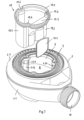
- das Ablaufgehäuse der Ablaufgarnitur mit einem Tauchrohr und einer Zwischenwand in einer perspektivischen Explosionsdarstellung;
- Fig. 8
- das Ablaufgehäuse im montierten Zustand an einer Bodenablauföffnung einer abschnittsweise dargestellten Duschwanne, mit eingesetztem Tauchrohr;
- Fig. 9
- das Tauchrohr aus
Fig. 8 , in einer perspektivischen Darstellung; - Fig. 10
- das Ablaufgehäuse im montierten Zustand an einer Bodenablauföffnung einer abschnittsweise dargestellten Duschwanne, mit eingesetztem, am oberen Ende abgelängtem Tauchrohr;
- Fig. 11
- das Tauchrohr aus
Fig. 10 , in einer perspektivischen Darstellung; - Fig. 12
- eine Vertikalschnittansicht des Ablaufgehäuses und des daraus entnommenen Tauchrohres;
- Fig. 13
- eine Vertikalschnittansicht des Ablaufgehäuses, wobei ein Abschnitt einer eine Überlaufkante definierenden Trennwand im Ablaufgehäuse muldenförmig verformt ist; und
- Fig. 14
- das Gehäuseunterteil des Ablaufgehäuses, wobei ein Abschnitt der eine Überlaufkante definierenden Trennwand im Ablaufgehäuse muldenförmig verformt ist, in einer perspektivischen Darstellung;
- Die in der Zeichnung gezeigte Ablaufgarnitur ist insbesondere zur Entwässerung einer Bade- oder Duschwanne 1 bestimmt. Sie weist ein Ablaufgehäuse 2 auf, das aus einem Gehäuseunterteil 2.1 und einem Gehäuseoberteil 2.2 gebildet ist. Die beiden Teile 2.1, 2.2 sind miteinander stoffschlüssig gefügt, beispielsweise verschweißt. Das Gehäuseoberteil 2.2 weist eine Aufnahme 3 für einen Dichtungsring 4 auf, der im montierten Zustand der Ablaufgarnitur die Ablauföffnung im Wannenboden umgebend, dichtend an der Unterseite der Duschwanne (Duschtasse) 1 anliegt.
- Zur Festlegung des Ablaufgehäuses 2 an der unteren Randfläche der Ablauföffnung der Duschwanne 1 ist ein Befestigungsflansch 5 vorgesehen, der sich mit einer umlaufenden Schrägfläche an die obere Randfläche der Ablauföffnung der Duschwanne anlegt, während der Dichtungsring 4 gegen die untere Randfläche der Ablauföffnung gepresst wird, und zwar durch Anziehen von Befestigungsschrauben 6, die in Durchstecköffnungen des Befestigungsflansches 5 gesteckt und in im Gehäuseoberteil 2.2 vorgesehene Gewindebohrungen eingeschraubt werden. Die Gewindebohrungen sind beispielsweise durch in das aus Kunststoff hergestellte Gehäuseoberteil 2.2 eingegossene Gewindehülsen gebildet. Der Befestigungsflansch 5 hat einen umlaufenden, zylindrischen Kragen oder Blechdurchzug 5.1, an den sich ein Flanschabschnitt 5.2 anschließt.
- Auf den Befestigungsflansch 5 bzw. die Befestigungsschrauben 6 ist eine Abdeckhaube 7 aufgesteckt, die an ihrer Unterseite stegförmige Abstandshalter 7.1 sowie hohlzylindrische Abstandshalter 7.2 zur formschlüssigen Aufnahme der Köpfe der Befestigungsschrauben 6 aufweist. Die Abdeckhaube 7 lässt sich zur Reinigung des Ablaufgehäuses 2 von den Befestigungsschrauben 6 manuell abnehmen.
- Das Gehäuseoberteil 2.2 und das Gehäuseunterteil 2.1 begrenzen einen Innenraum 8, der von der in dem Gehäuseoberteil ausgebildeten Einlassöffnung (Zulauföffnung) 9 her zugänglich ist. An dem Gehäuseunterteil 2.1 ist ein Ablaufstutzen 10 angeformt, an dem eine Ablaufrohrleitung 11 angeschlossen werden kann. Der Ablaufstutzen 10 weist hierzu ein Außengewinde 12 auf, so dass die in den Ablaufstutzen 10 eingesteckte Ablaufrohrleitung 11 mit einer Überwurfmutter 13 dichtend und kraftschlüssig mit dem Ablaufstutzen 10 verbunden werden kann.
- Das Ablaufgehäuse 2, und zwar das Gehäuseunterteil 2.1 umfasst des Weiteren zwischen dem Innenraum 8 und dem Ablaufstutzen 10 eine Trennwand 14, die eine Überlaufkante 15 definiert. Die Trennwand 14 ist integraler Bestandteil des Ablaufgehäuses 2 und einstückig mit dem Gehäuseunterteil 2.1 verbunden. Das Gehäuseunterteil 2.1 definiert zusammen mit der Trennwand 14 einen Aufnahmeraum 16 zur Aufnahme von Sperrwasser. Das Gehäuseunterteil 2.1 weist dabei einen sich relativ zu dem Aufnahmeraum 16 nach außen erstreckenden Absatz (Boden) 2.11 auf, der in eine sich nach oben in Richtung des Gehäuseoberteils 2.2 erstreckende Gehäusewand 2.12 übergeht. Die Gehäusewand 2.12, der Absatz (Boden) 2.11 und die Trennwand 14 definieren einen ringförmigen Ablaufkanal 17, der in den Ablaufstutzen 10 mündet. Der Boden 2.11 des ringförmigen Ablaufkanals 17 ist zu dem Ablaufstutzen 10 hin geneigt.
- Des Weiteren umfasst die Ablaufgarnitur ein in das Gehäuse 2 eingesetztes und aus demselben entnehmbares Tauchrohr 19, das zusammen mit dem topfförmigen Abschnitt 20 des Gehäuseunterteils 2.1 und der Trennwand 14 einen Geruchverschluss bildet. Das Tauchrohr 19 weist an seinem oberen Ende einen Kragen 19.1 auf, mit dem es in die Einlassöffnung 9 des Ablaufgehäuses 2 formschlüssig eingesetzt werden kann. Der Kragen 19.1 steht gegenüber dem rohrförmigen Abschnitt 19.5 des Tauchrohrs 19 radial nach außen vor. Im oberen Ende des Tauchrohres 19 ist vorzugsweise ein Griff (nicht gezeigt) vorgesehen, so dass das Tauchrohr leicht ergriffen und aus dem Ablaufgehäuse 2 herausgezogen werden kann. Die freie Querschnittsfläche des Tauchrohres 19 ist deutlich größer als die freie Querschnittsfläche des Ablaufstutzens 10 (vgl.
Fig. 7 ). In den dargestellten Ausführungsbeispielen beträgt die freie Querschnittsfläche des Tauchrohres 19 beispielsweise mehr als 1,5-fache der freien Querschnittsfläche des Ablaufstutzens 10. Es ist zu erkennen, dass der Innenraum 8 des Ablaufgehäuses 2 nach Entnahme des Tauchrohres 19 für Reinigungszwecke gut zugänglich ist. - Das Tauchrohr 19 hat ausgehend von seinem unteren Ende bis zu seinem oberen Kragen 19.1 ein nicht-kreisringförmiges Querschnittsprofil mit einem Rohrwandabschnitt 19.2, der dem Wandabschnitt 14.1 der Trennwand 14 zugeordnet ist (vgl.
Fig. 8 bis 11 ). Der Rohrwandabschnitt 19.2 weist ein Außenprofil auf, in welches der nach innen gewölbte Trennwandabschnitt 14.1 hineinragt. Des Weiteren weist das Tauchrohr 19 einen radial nach außen vorstehenden Einlaufflächenabschnitt 19.3 auf, der im eingesetzten Zustand des Tauchrohres 19 den nach innen gewölbten Trennwandabschnitt 14.1 nach außen überkragt (vgl.Fig. 3 ). Der Einlaufflächenabschnitt 19.3 ist ausgehend vom Kragen 19.1 des Tauchrohres zu dessen rohrförmigen Abschnitt 19.5 hin geneigt. Im Bereich seines Kragens 19.1 sowie im Bereich seines rohrförmigen Abschnitts 19.5 weist das Tauchrohr 19 vertikal verlaufende Ausnehmungen oder Nischen 19.6 auf, die der formschlüssigen Aufnahme von im Gehäuseunterteil 2.1 und im Gehäuseoberteil 2.2 ausgebildeten Schraubdomen 2.13, 2.21 dienen. - Mittels des ringförmigen Tauchrohrkragens 19.1 lässt sich ein Hohlraum 22 überdecken und abdichten, der an der Duschwannenbodenöffnung zwischen dem Ablaufgehäuse 2 und dem Befestigungsflansch 5 liegt und in welchem sich ohne die Überdeckung mittels des Kragens 19.1 Schmutznester bilden können. Um je nach Ausgestaltung der Wannenbodenöffnung unterschiedlich hohe Hohlräume 22 überdecken zu können und damit das Auftreten von Schmutznester zu vermeiden, weist der Kragen 19.1 im Auslieferzustand eine gewisse Höhe auf, die durch vertikale Kürzung an die Höhe des zu überdeckenden Hohlraums 22 angepasst werden kann. Der Tauchrohrkragen 19.1 liegt dichtend an dem Kragen oder Blechdurchzug 5.1 des Befestigungsflansches 5 an.
- Um ein möglichst ebenes, rechtwinkliges Ablängen des Tauchrohrkragens 19.1 relativ zu der Längsmittelachse des Tauchrohres 19 zu erleichtern, weist der Kragen 19.1 eine Vielzahl von sich in vertikaler Richtung einander abwechselnden ringförmigen Kragenabschnitten 19.11, 19.12 auf, die sich voneinander durch eine unterschiedliche Materialhärte und/oder durch eine unterschiedliche Kragenwanddicke unterscheiden. Die unterschiedlichen Kragenabschnitte 19.11, 19.12 des Tauchrohres 19 lassen sich durch Zwei- oder Mehrkomponenten-Spritzgießen verwirklichen. Der jeweilige härtere Kragenabschnitt oder Kragenabschnitt mit geringerer Wanddicke erleichtert die Führung eines Schneidwerkzeuges beim passenden Kürzen des Kragens 19.1.
- Beispielsweise weist der ringförmige Kragen 19.1 des Tauchrohrs 19 im ungekürzten Auslieferungszustand mindestens vier, vorzugsweise mindestens sechs, besonders bevorzugt mindestens acht solcher Kragenabschnitte 19.11, 19.12 auf.
- Die Kragenabschnitte 19.11, 19.12 sind vertikal abwechselnd vorzugsweise aus einer Weichkomponente, beispielsweise aus einem Elastomer oder aus einem Polyolefin, und aus einer Hartkomponente, vorzugsweise aus thermoplastischem Kunststoff, besonders bevorzugt aus Polypropylen, gefertigt. Ferner ist der Kragen 19.1 so bemessen ist, dass er im eingesetzten Zustand des Tauchrohres 19 eine Presspassung oder Übergangspassung mit dem Befestigungsflansch 5 bildet. Vorzugsweise wird die Presspassung oder Übergangspassung des Kragens 19.1 mit dem Befestigungsflansch 5 durch mindestens einen der aus einer Weichkomponente gefertigten ringförmigen Kragenabschnitte 19.12 bewirkt. Wie insbesondere in
Fig. 8 gezeigt, stehen die aus einer Weichkomponente gefertigten ringförmigen Kragenabschnitte 19.12 gegenüber den aus einer Hartkomponente gefertigten ringförmigen Kragenabschnitten 19.11 nach außen umlaufend vor. Der aus einer Weichkomponente gefertigte Abschnitt 19.12 des Tauchrohrkragens, der an dem Blechdurchzug oder Kragen 5.1 des Befestigungsflansches 5 anliegt, bildet zusammen mit letzterem eine Abdichtung des Hohlraums 22. - Die eine Überlaufkante 15 definierende Trennwand 14 ist flexibel verformbar ausgeführt, so dass ein Abschnitt der Überlaufkante 15 durch mechanische Druckeinwirkung muldenförmig verformt werden kann (vgl.
Fig. 12 und13 ). Somit ist auch ein in Fließrichtung des Abwassers gesehen hinter der Trennwand 14 gelegener Abschnitt des Gehäuses 2 für Reinigungszwecke gut zugänglich. Um die Trennwand 14 an der Überlaufkante 15 flexibel muldenförmig verformen oder umkrempeln zu können, ist die Trennwand 14 beispielsweise aus einer Weichkomponente, vorzugsweise aus einem Elastomer oder aus einem Polyolefin, gefertigt. Dagegen sind das Gehäuseunterteil 2.1 sowie das Gehäuseoberteil 2.2 vorzugsweise aus einer Hartkomponente gefertigt, beispielsweise aus thermoplastischem Kunststoff, besonders bevorzugt aus Polypropylen. Die einstückige Verbindung von Trennwand 14 und Gehäuseunterteil 2.1, die aus unterschiedlichen Komponenten hergestellt werden, lässt sich durch Zwei- oder Mehrkomponenten-Spritzgießen verwirklichen. - Die Trennwand 14 ist insbesondere derart flexibel verformbar, dass ein Abschnitt der Überlaufkante 15 durch Druckeinwirkung seitlich in Richtung des Innenraums 8 des Gehäuses 2 muldenförmig verformt werden kann (vgl.
Fig. 13 und14 ). - In den
Figuren 5 und14 ist zu sehen, dass die Trennwand 14 einen im Querschnitt bogenförmigen, nach innen in Richtung Innenraum 8 bzw. Tauchrohr 19 gewölbten Wandabschnitt 14.1 aufweist, dessen konkave Seite dem Ablaufstutzen 10 zugewandt ist. Im Bereich des Abschnitts 14.1 ist die Trennwand derart flexibel verformbar, dass ein Abschnitt der Überlaufkante 15 durch mechanische Druckeinwirkung seitlich in Richtung des Ablaufstutzens 10 muldenförmig verformt werden kann. Ferner ist der Trennwandabschnitt 14.1 über eine im Wesentlichen U-förmige Dünnstelle 14.2 flüssigkeitsdicht mit der Trennwand 14 verbunden. Die Dünnstelle 14.2 kann auch als Abreißnut oder Abreißkante bezeichnet werden. Sie erleichtert ein Herausschneiden bzw. Herausreißen des Wandabschnitts 14.1 in nicht erfindungsgemäßen Anwendungsfällen, die eine Geruchverschlussfunktion der Ablaufgarnitur nicht erfordern. Solche Anwendungsfälle existieren beispielsweise in Südeuropa, wo Ablaufsysteme verlangt werden, die einen zentralen Bodenablauf 21 mit Geruchverschluss aufweisen, über den alle wasserabführenden Sanitärgegenstände, insbesondere Duschwannen, ausgenommenen Toiletten, entwässert werden (vgl.Fig. 1 ). In solchen Ablaufsystemen mit Zentralgeruchverschluss kann die erfindungsgemäße Ablaufgarnitur in einem nicht erfindungsgemäßen Zustand auch ohne das Tauchrohr 19 und ohne den heraustrennbaren Wandabschnitt 14.1 der Trennwand 14 betrieben werden. - Die Ausführung der Erfindung ist nicht auf die in der Zeichnung dargestellten Ausführungsbeispiele beschränkt. Vielmehr sind zahlreiche Varianten denkbar, die auch bei von den gezeigten Ausführungsbeispielen abweichender Gestaltung von der in den Ansprüchen offenbarten Erfindung Gebrauch machen.
Claims (15)
- Ablaufgarnitur, insbesondere für Dusch- oder Badewannen, mit einem Ablaufgehäuse (2), das einen von einer oberen Einlassöffnung (9) her zugänglichen Innenraum (8) aufweist, mit einem von dem Ablaufgehäuse abstehenden Ablaufstutzen (10), mit einer eine Überlaufkante (15) definierenden Trennwand (14) zwischen dem Innenraum (8) und dem Ablaufstutzen (10), mit einem in das Ablaufgehäuse (2) eingesetzten, aus demselben entnehmbaren, einen Teil eines Geruchverschlusses bildenden Tauchrohr (19), und mit einem Befestigungsflansch (5) zur Festlegung des Ablaufgehäuses (2) an einer Ablauföffnung einer Dusch- oder Badewanne, dadurch gekennzeichnet, dass das Tauchrohr (19) an seinem oberen Ende einen kürzbaren ringförmigen Kragen (19.1) aufweist, der eine Vielzahl von sich in vertikaler Richtung einander abwechselnden ringförmigen Kragenabschnitten (19.11, 19.12) aufweist, die sich voneinander durch eine unterschiedliche Materialhärte und/oder durch eine unterschiedliche Kragenwanddicke unterscheiden, wobei der ringförmige Kragen (19.1) im ungekürzten Auslieferungszustand mindestens vier, vorzugsweise mindestens sechs solcher Kragenabschnitte (19.11, 19.12) aufweist, und wobei sich mittels des Kragens (19.1) im montierten Zustand der Ablaufgarnitur ein Hohlraum (22), der im Bereich der Ablauföffnung der Dusch- oder Badewanne zwischen dem auf der Unterseite des Wannenbodens angeordneten Ablaufgehäuse (2) und dem auf der Oberseite des Wannenbodens angeordneten Befestigungsflansch (5) liegt, überdecken lässt.
- Ablaufgarnitur nach Anspruch 1, dadurch gekennzeichnet, dass die ringförmigen Kragenabschnitte (19.11, 19.12) vertikal abwechselnd aus einer Weichkomponente, vorzugsweise aus einem Elastomer oder aus einem Polyolefin, und aus einer Hartkomponente, vorzugsweise aus thermoplastischem Kunststoff, besonders bevorzugt aus Polypropylen, gefertigt sind.
- Ablaufgarnitur nach Anspruch 2, dadurch gekennzeichnet, dass die aus einer Weichkomponente gefertigten ringförmigen Kragenabschnitte (19.12) gegenüber den aus einer Hartkomponente gefertigten ringförmigen Kragenabschnitten (19.11) nach außen vorstehen.
- Ablaufgarnitur nach einem der Ansprüche 1 bis 3, dadurch gekennzeichnet, dass der Kragen (19.1) des Tauchrohres (19) so bemessen ist, dass er im eingesetzten Zustand des Tauchrohres (19) eine Presspassung oder Übergangspassung mit dem Befestigungsflansch (5) bildet.
- Ablaufgarnitur nach einem der Ansprüche 1 bis 4, dadurch gekennzeichnet, dass der Kragen (19.1) vertikal verlaufende Nischen (19.6) zur formschlüssigen Aufnahme von im Ablaufgehäuse (2) ausgebildeten Schraubdomen (2.13, 2.21) aufweist.
- Ablaufgarnitur nach einem der Ansprüche 1 bis 5, dadurch gekennzeichnet, dass die Trennwand (14) einen bogenförmigen, nach innen in Richtung Tauchrohr (19) gewölbten Wandabschnitt (14.1) aufweist, der dem Ablaufstutzen (10) zugewandt ist.
- Ablaufgarnitur nach Anspruch 6, dadurch gekennzeichnet, dass der bogenförmige, nach innen in Richtung Tauchrohr gewölbte Wandabschnitt (14.1) der Trennwand (14) über eine im Wesentlichen U-förmige Dünnstelle (14.2) flüssigkeitsdicht mit der Trennwand (14) verbunden ist.
- Ablaufgarnitur nach Anspruch 6 oder 7, dadurch gekennzeichnet, dass das Tauchrohr (19) ein nicht-kreisringförmiges Querschnittsprofil mit einem Rohrwandabschnitt (19.2) aufweist, der dem nach innen gewölbten Wandabschnitt (14.1) der Trennwand (14) zugeordnet ist, wobei der Rohrwandabschnitt (19.2) ein Außenprofil aufweist, in welches der Wandabschnitt (14.1) der Trennwand (14) hineinragt oder formschlüssig eingreift.
- Ablaufgarnitur nach einem der Ansprüche 6 bis 8, dadurch gekennzeichnet, dass das Tauchrohr (19) einen radial nach außen vorstehenden Einlaufflächenabschnitt (19.3) aufweist, der im eingesetzten Zustand des Tauchrohres (19) den nach innen gewölbten Wandabschnitt (14.1) der Trennwand (14) nach außen überkragt.
- Ablaufgarnitur nach einem der Ansprüche 1 bis 9, dadurch gekennzeichnet, dass die Trennwand (14) flexibel verformbar ist, derart, dass ein Abschnitt der Überlaufkante (15) durch mechanische Druckeinwirkung muldenförmig verformbar ist.
- Ablaufgarnitur nach einem der Ansprüche 1 bis 10, dadurch gekennzeichnet, dass die Trennwand (14) derart flexibel verformbar ist, dass ein Abschnitt der Überlaufkante durch mechanische Druckeinwirkung seitlich in Richtung des Innenraums (8) des Ablaufgehäuses (2) muldenförmig verformbar ist.
- Ablaufgarnitur nach einem der Ansprüche 1 bis 11, dadurch gekennzeichnet, dass die Trennwand (14) derart flexibel verformbar ist, dass ein Abschnitt der Überlaufkante (15) durch mechanische Druckeinwirkung seitlich in Richtung des Ablaufstutzens (10) muldenförmig verformbar ist.
- Ablaufgarnitur nach einem der Ansprüche 1 bis 12, dadurch gekennzeichnet, dass das Ablaufgehäuse (2) aus einem Gehäuseunterteil (2.1) und einem Gehäuseoberteil (2.2) zusammengesetzt ist, wobei das Gehäuseunterteil (2.1) zusammen mit der Trennwand (14) einen Aufnahmeraum (16) zur Aufnahme von Sperrwasser definiert, wobei das Gehäuseunterteil (2.1) einen sich relativ zu dem Aufnahmeraum (16) nach außen erstreckenden Absatz (2.11) aufweist, wobei der Absatz (2.11) in eine sich nach oben in Richtung des Gehäuseoberteils (2.2) erstreckende Gehäusewand (2.12) übergeht, und wobei die Gehäusewand (2.12), der Absatz (2.11) und die Trennwand (14) einen Ablaufkanal (17) definieren, der in den Ablaufstutzen (10) mündet.
- Ablaufgarnitur nach einem der Ansprüche 1 bis 13, dadurch gekennzeichnet, dass die Trennwand (14) aus einer Weichkomponente, vorzugsweise aus einem Elastomer oder aus einem Polyolefin, gefertigt ist.
- Ablaufgarnitur nach Anspruch 13 oder 14 in Kombination mit Anspruch 13, dadurch gekennzeichnet, dass das Gehäuseunterteil (2.1) und/oder das Gehäuseoberteil (2.2) aus einer Hartkomponente, vorzugsweise aus thermoplastischem Kunststoff, besonders bevorzugt aus Polypropylen, gefertigt sind.
Applications Claiming Priority (1)
| Application Number | Priority Date | Filing Date | Title |
|---|---|---|---|
| DE202021100191.7U DE202021100191U1 (de) | 2021-01-15 | 2021-01-15 | Ablaufgarnitur, insbesondere für Duschwannen, mit variabel ablängbarem Tauchrohr |
Publications (2)
| Publication Number | Publication Date |
|---|---|
| EP4030006A1 EP4030006A1 (de) | 2022-07-20 |
| EP4030006B1 true EP4030006B1 (de) | 2025-05-21 |
Family
ID=79024143
Family Applications (1)
| Application Number | Title | Priority Date | Filing Date |
|---|---|---|---|
| EP21214945.4A Active EP4030006B1 (de) | 2021-01-15 | 2021-12-16 | Ablaufgarnitur, insbesondere für duschwannen, mit variabel ablängbarem tauchrohr |
Country Status (3)
| Country | Link |
|---|---|
| EP (1) | EP4030006B1 (de) |
| DE (1) | DE202021100191U1 (de) |
| ES (1) | ES3031263T3 (de) |
Family Cites Families (8)
| Publication number | Priority date | Publication date | Assignee | Title |
|---|---|---|---|---|
| DE19649239A1 (de) * | 1996-06-27 | 1998-01-02 | Scheffer Ohg Franz | Ablaufarmatur mit einstellbarem Tauchrohr und geschweißtem Gehäuse |
| EP0816580A3 (de) | 1996-06-27 | 1998-09-16 | FRANZ SCHEFFER oHG | Ablaufarmatur mit einstellbarem Tauchrohr und geschweisstem Gehäuse |
| DE19651405A1 (de) * | 1996-12-11 | 1998-06-18 | Bonomini S R L | Überprüfbarer Siphon für Duschwannen, Badewannen oder dergleichen |
| EP1775395B1 (de) * | 2005-10-11 | 2010-03-17 | Geberit International AG | Ablaufarmatur für sanitäre Anlagen |
| DE202008010106U1 (de) * | 2008-07-28 | 2009-12-10 | Viega Gmbh & Co. Kg | Ablaufgarnitur mit einem einen flexiblen Behälter aufweisenden Geruchverschluss |
| DE202010002777U1 (de) | 2010-02-24 | 2011-07-26 | Viega Gmbh & Co. Kg | Ablaufgarnitur mit Reinigungsöffnung |
| FR3016177A1 (fr) * | 2014-01-08 | 2015-07-10 | Eiffage Construction | Avaloir-siphon de sol a encastrer, installation d'evacuation a avaloir-siphon et procede de realisation |
| SE539987C2 (en) | 2016-06-08 | 2018-02-20 | Bls Ind Ab 556361 1887 | Odor trap unit |
-
2021
- 2021-01-15 DE DE202021100191.7U patent/DE202021100191U1/de active Active
- 2021-12-16 ES ES21214945T patent/ES3031263T3/es active Active
- 2021-12-16 EP EP21214945.4A patent/EP4030006B1/de active Active
Also Published As
| Publication number | Publication date |
|---|---|
| DE202021100191U1 (de) | 2022-04-20 |
| EP4030006A1 (de) | 2022-07-20 |
| ES3031263T3 (en) | 2025-07-07 |
Similar Documents
| Publication | Publication Date | Title |
|---|---|---|
| EP2363543B1 (de) | Ablaufgarnitur mit Reinigungsöffnung | |
| EP1878508B1 (de) | Kopfbrause | |
| EP3839157B1 (de) | Ablaufarmatur für eine sanitäre wanne oder duschtasse | |
| EP2149643B1 (de) | Ablaufgarnitur mit einem einen flexiblen Behälter aufweisenden Geruchverschluss | |
| EP2083125B1 (de) | Ablaufarmatur, insbesondere für Dusch- oder Badewannen | |
| WO2019020403A1 (de) | Geruchsverschlussvorichtung für sanitärvorrichtungen, insbesondere urinale | |
| DE102009023015B4 (de) | Ablauf, insbesondere für sanitäre Einrichtungen | |
| EP0436093B1 (de) | Ablaufarmatur für eine Brausewanne | |
| EP3117047B1 (de) | Ablaufgarnitur für eine bodenablaufrinne und bodenablaufrinne mit einer solchen ablaufgarnitur | |
| EP2157247B1 (de) | Ablauf | |
| EP3567170B1 (de) | Ablaufarmatur für eine dusch- oder badewanne | |
| EP4030006B1 (de) | Ablaufgarnitur, insbesondere für duschwannen, mit variabel ablängbarem tauchrohr | |
| EP4030007B1 (de) | Ablaufgarnitur, insbesondere für duschwannen, mit flexibel verformbarer trennwand | |
| EP2258905A1 (de) | Ablauf, insbesondere für sanitäre Einrichtungen | |
| EP3295847A1 (de) | Abflussabdeckung mit haarfänger | |
| EP0807721B1 (de) | Ablaufarmatur für Dusch- und Badewannen für Keller, Balkone, Terrassen o. dgl. | |
| EP3839158B1 (de) | Duschtasse | |
| EP0816580A2 (de) | Ablaufarmatur mit einstellbarem Tauchrohr und geschweisstem Gehäuse | |
| EP3354808B1 (de) | Ablaufgarnitur mit heb- und senkbarem ablaufstopfen | |
| DE69922947T2 (de) | Wassereinlauf für Badewanne in Form einer Kaskade | |
| EP3835499B1 (de) | Ablaufarmatur, insbesondere für eine duschwanne oder in form eines bodenablaufs | |
| DE3918321A1 (de) | Ablauf mit einem wassergeruchsverschlusseinsatz | |
| EP2703573B1 (de) | Ablaufgarnitur und Badewanne bzw. Duschtasse mit einer derartigen Ablaufgarnitur | |
| EP1574629B1 (de) | Ablaufarmatur für eine sanitäre Apparatur, insbesondere Duschwanne | |
| DE19649239A1 (de) | Ablaufarmatur mit einstellbarem Tauchrohr und geschweißtem Gehäuse |
Legal Events
| Date | Code | Title | Description |
|---|---|---|---|
| PUAI | Public reference made under article 153(3) epc to a published international application that has entered the european phase |
Free format text: ORIGINAL CODE: 0009012 |
|
| STAA | Information on the status of an ep patent application or granted ep patent |
Free format text: STATUS: THE APPLICATION HAS BEEN PUBLISHED |
|
| AK | Designated contracting states |
Kind code of ref document: A1 Designated state(s): AL AT BE BG CH CY CZ DE DK EE ES FI FR GB GR HR HU IE IS IT LI LT LU LV MC MK MT NL NO PL PT RO RS SE SI SK SM TR |
|
| STAA | Information on the status of an ep patent application or granted ep patent |
Free format text: STATUS: REQUEST FOR EXAMINATION WAS MADE |
|
| 17P | Request for examination filed |
Effective date: 20230120 |
|
| RBV | Designated contracting states (corrected) |
Designated state(s): AL AT BE BG CH CY CZ DE DK EE ES FI FR GB GR HR HU IE IS IT LI LT LU LV MC MK MT NL NO PL PT RO RS SE SI SK SM TR |
|
| GRAP | Despatch of communication of intention to grant a patent |
Free format text: ORIGINAL CODE: EPIDOSNIGR1 |
|
| STAA | Information on the status of an ep patent application or granted ep patent |
Free format text: STATUS: GRANT OF PATENT IS INTENDED |
|
| INTG | Intention to grant announced |
Effective date: 20241220 |
|
| GRAS | Grant fee paid |
Free format text: ORIGINAL CODE: EPIDOSNIGR3 |
|
| GRAA | (expected) grant |
Free format text: ORIGINAL CODE: 0009210 |
|
| STAA | Information on the status of an ep patent application or granted ep patent |
Free format text: STATUS: THE PATENT HAS BEEN GRANTED |
|
| AK | Designated contracting states |
Kind code of ref document: B1 Designated state(s): AL AT BE BG CH CY CZ DE DK EE ES FI FR GB GR HR HU IE IS IT LI LT LU LV MC MK MT NL NO PL PT RO RS SE SI SK SM TR |
|
| REG | Reference to a national code |
Ref country code: GB Ref legal event code: FG4D Free format text: NOT ENGLISH |
|
| REG | Reference to a national code |
Ref country code: CH Ref legal event code: EP |
|
| REG | Reference to a national code |
Ref country code: DE Ref legal event code: R096 Ref document number: 502021007522 Country of ref document: DE |
|
| REG | Reference to a national code |
Ref country code: IE Ref legal event code: FG4D Free format text: LANGUAGE OF EP DOCUMENT: GERMAN |
|
| REG | Reference to a national code |
Ref country code: NL Ref legal event code: FP |
|
| REG | Reference to a national code |
Ref country code: ES Ref legal event code: FG2A Ref document number: 3031263 Country of ref document: ES Kind code of ref document: T3 Effective date: 20250707 |
|
| PG25 | Lapsed in a contracting state [announced via postgrant information from national office to epo] |
Ref country code: FI Free format text: LAPSE BECAUSE OF FAILURE TO SUBMIT A TRANSLATION OF THE DESCRIPTION OR TO PAY THE FEE WITHIN THE PRESCRIBED TIME-LIMIT Effective date: 20250521 Ref country code: PT Free format text: LAPSE BECAUSE OF FAILURE TO SUBMIT A TRANSLATION OF THE DESCRIPTION OR TO PAY THE FEE WITHIN THE PRESCRIBED TIME-LIMIT Effective date: 20250922 |
|
| REG | Reference to a national code |
Ref country code: LT Ref legal event code: MG9D |
|
| PG25 | Lapsed in a contracting state [announced via postgrant information from national office to epo] |
Ref country code: NO Free format text: LAPSE BECAUSE OF FAILURE TO SUBMIT A TRANSLATION OF THE DESCRIPTION OR TO PAY THE FEE WITHIN THE PRESCRIBED TIME-LIMIT Effective date: 20250821 Ref country code: GR Free format text: LAPSE BECAUSE OF FAILURE TO SUBMIT A TRANSLATION OF THE DESCRIPTION OR TO PAY THE FEE WITHIN THE PRESCRIBED TIME-LIMIT Effective date: 20250822 |
|
| PG25 | Lapsed in a contracting state [announced via postgrant information from national office to epo] |
Ref country code: PL Free format text: LAPSE BECAUSE OF FAILURE TO SUBMIT A TRANSLATION OF THE DESCRIPTION OR TO PAY THE FEE WITHIN THE PRESCRIBED TIME-LIMIT Effective date: 20250521 |
|
| PG25 | Lapsed in a contracting state [announced via postgrant information from national office to epo] |
Ref country code: BG Free format text: LAPSE BECAUSE OF FAILURE TO SUBMIT A TRANSLATION OF THE DESCRIPTION OR TO PAY THE FEE WITHIN THE PRESCRIBED TIME-LIMIT Effective date: 20250521 |
|
| PG25 | Lapsed in a contracting state [announced via postgrant information from national office to epo] |
Ref country code: HR Free format text: LAPSE BECAUSE OF FAILURE TO SUBMIT A TRANSLATION OF THE DESCRIPTION OR TO PAY THE FEE WITHIN THE PRESCRIBED TIME-LIMIT Effective date: 20250521 |
|
| PG25 | Lapsed in a contracting state [announced via postgrant information from national office to epo] |
Ref country code: RS Free format text: LAPSE BECAUSE OF FAILURE TO SUBMIT A TRANSLATION OF THE DESCRIPTION OR TO PAY THE FEE WITHIN THE PRESCRIBED TIME-LIMIT Effective date: 20250821 |
|
| PG25 | Lapsed in a contracting state [announced via postgrant information from national office to epo] |
Ref country code: IS Free format text: LAPSE BECAUSE OF FAILURE TO SUBMIT A TRANSLATION OF THE DESCRIPTION OR TO PAY THE FEE WITHIN THE PRESCRIBED TIME-LIMIT Effective date: 20250921 |
|
| PG25 | Lapsed in a contracting state [announced via postgrant information from national office to epo] |
Ref country code: LV Free format text: LAPSE BECAUSE OF FAILURE TO SUBMIT A TRANSLATION OF THE DESCRIPTION OR TO PAY THE FEE WITHIN THE PRESCRIBED TIME-LIMIT Effective date: 20250521 |
|
| PGFP | Annual fee paid to national office [announced via postgrant information from national office to epo] |
Ref country code: DE Payment date: 20251217 Year of fee payment: 5 |
|
| PG25 | Lapsed in a contracting state [announced via postgrant information from national office to epo] |
Ref country code: SM Free format text: LAPSE BECAUSE OF FAILURE TO SUBMIT A TRANSLATION OF THE DESCRIPTION OR TO PAY THE FEE WITHIN THE PRESCRIBED TIME-LIMIT Effective date: 20250521 Ref country code: DK Free format text: LAPSE BECAUSE OF FAILURE TO SUBMIT A TRANSLATION OF THE DESCRIPTION OR TO PAY THE FEE WITHIN THE PRESCRIBED TIME-LIMIT Effective date: 20250521 |
|
| PGFP | Annual fee paid to national office [announced via postgrant information from national office to epo] |
Ref country code: AT Payment date: 20260113 Year of fee payment: 5 |
|
| PGFP | Annual fee paid to national office [announced via postgrant information from national office to epo] |
Ref country code: IT Payment date: 20251222 Year of fee payment: 5 |
|
| PGFP | Annual fee paid to national office [announced via postgrant information from national office to epo] |
Ref country code: NL Payment date: 20251218 Year of fee payment: 5 Ref country code: FR Payment date: 20251217 Year of fee payment: 5 |
|
| PG25 | Lapsed in a contracting state [announced via postgrant information from national office to epo] |
Ref country code: CZ Free format text: LAPSE BECAUSE OF FAILURE TO SUBMIT A TRANSLATION OF THE DESCRIPTION OR TO PAY THE FEE WITHIN THE PRESCRIBED TIME-LIMIT Effective date: 20250521 |
|
| PG25 | Lapsed in a contracting state [announced via postgrant information from national office to epo] |
Ref country code: EE Free format text: LAPSE BECAUSE OF FAILURE TO SUBMIT A TRANSLATION OF THE DESCRIPTION OR TO PAY THE FEE WITHIN THE PRESCRIBED TIME-LIMIT Effective date: 20250521 |
|
| PG25 | Lapsed in a contracting state [announced via postgrant information from national office to epo] |
Ref country code: RO Free format text: LAPSE BECAUSE OF FAILURE TO SUBMIT A TRANSLATION OF THE DESCRIPTION OR TO PAY THE FEE WITHIN THE PRESCRIBED TIME-LIMIT Effective date: 20250521 Ref country code: SK Free format text: LAPSE BECAUSE OF FAILURE TO SUBMIT A TRANSLATION OF THE DESCRIPTION OR TO PAY THE FEE WITHIN THE PRESCRIBED TIME-LIMIT Effective date: 20250521 |