EP4029902A1 - Thermoplastische polymerteilchen und verfahren zu ihrer herstellung - Google Patents
Thermoplastische polymerteilchen und verfahren zu ihrer herstellung Download PDFInfo
- Publication number
- EP4029902A1 EP4029902A1 EP20862372.8A EP20862372A EP4029902A1 EP 4029902 A1 EP4029902 A1 EP 4029902A1 EP 20862372 A EP20862372 A EP 20862372A EP 4029902 A1 EP4029902 A1 EP 4029902A1
- Authority
- EP
- European Patent Office
- Prior art keywords
- thermoplastic polymer
- particles
- preparing
- polymer particles
- nozzle
- Prior art date
- Legal status (The legal status is an assumption and is not a legal conclusion. Google has not performed a legal analysis and makes no representation as to the accuracy of the status listed.)
- Withdrawn
Links
- 239000002245 particle Substances 0.000 title claims abstract description 381
- 229920001169 thermoplastic Polymers 0.000 title claims abstract description 253
- 238000000034 method Methods 0.000 title claims abstract description 62
- 239000002952 polymeric resin Substances 0.000 claims abstract description 153
- 238000001816 cooling Methods 0.000 claims abstract description 63
- 229920003002 synthetic resin Polymers 0.000 claims abstract description 55
- 239000011261 inert gas Substances 0.000 claims abstract description 26
- 239000007789 gas Substances 0.000 claims description 137
- 238000005507 spraying Methods 0.000 claims description 126
- 229920000642 polymer Polymers 0.000 claims description 56
- IJGRMHOSHXDMSA-UHFFFAOYSA-N Atomic nitrogen Chemical compound N#N IJGRMHOSHXDMSA-UHFFFAOYSA-N 0.000 claims description 36
- 238000007599 discharging Methods 0.000 claims description 36
- 239000011159 matrix material Substances 0.000 claims description 24
- -1 polypropylene Polymers 0.000 claims description 22
- 239000004695 Polyether sulfone Substances 0.000 claims description 20
- 229920000747 poly(lactic acid) Polymers 0.000 claims description 20
- 229920006393 polyether sulfone Polymers 0.000 claims description 20
- 239000004626 polylactic acid Substances 0.000 claims description 20
- 229920002803 thermoplastic polyurethane Polymers 0.000 claims description 20
- 239000004743 Polypropylene Substances 0.000 claims description 18
- 229920001155 polypropylene Polymers 0.000 claims description 18
- 239000004952 Polyamide Substances 0.000 claims description 15
- 239000004433 Thermoplastic polyurethane Substances 0.000 claims description 15
- 238000001125 extrusion Methods 0.000 claims description 15
- 229920002647 polyamide Polymers 0.000 claims description 15
- JTJMJGYZQZDUJJ-UHFFFAOYSA-N phencyclidine Chemical class C1CCCCN1C1(C=2C=CC=CC=2)CCCCC1 JTJMJGYZQZDUJJ-UHFFFAOYSA-N 0.000 claims description 9
- XKRFYHLGVUSROY-UHFFFAOYSA-N Argon Chemical compound [Ar] XKRFYHLGVUSROY-UHFFFAOYSA-N 0.000 claims description 6
- 229910052757 nitrogen Inorganic materials 0.000 claims description 6
- 229910052786 argon Inorganic materials 0.000 claims description 3
- 239000001307 helium Substances 0.000 claims description 3
- 229910052734 helium Inorganic materials 0.000 claims description 3
- SWQJXJOGLNCZEY-UHFFFAOYSA-N helium atom Chemical compound [He] SWQJXJOGLNCZEY-UHFFFAOYSA-N 0.000 claims description 3
- 239000000155 melt Substances 0.000 claims description 3
- 229910052754 neon Inorganic materials 0.000 claims description 3
- GKAOGPIIYCISHV-UHFFFAOYSA-N neon atom Chemical compound [Ne] GKAOGPIIYCISHV-UHFFFAOYSA-N 0.000 claims description 3
- 230000000052 comparative effect Effects 0.000 description 101
- 229920005989 resin Polymers 0.000 description 62
- 239000011347 resin Substances 0.000 description 62
- 239000003570 air Substances 0.000 description 55
- 238000004364 calculation method Methods 0.000 description 33
- 239000007921 spray Substances 0.000 description 27
- 238000009826 distribution Methods 0.000 description 26
- 229910001873 dinitrogen Inorganic materials 0.000 description 24
- 230000000704 physical effect Effects 0.000 description 18
- 238000002360 preparation method Methods 0.000 description 17
- 230000008569 process Effects 0.000 description 14
- 230000009477 glass transition Effects 0.000 description 13
- 239000002904 solvent Substances 0.000 description 12
- 239000000843 powder Substances 0.000 description 11
- 230000014759 maintenance of location Effects 0.000 description 9
- 239000000047 product Substances 0.000 description 8
- 238000005979 thermal decomposition reaction Methods 0.000 description 8
- 229920005992 thermoplastic resin Polymers 0.000 description 7
- 230000008901 benefit Effects 0.000 description 6
- 230000001186 cumulative effect Effects 0.000 description 6
- 239000012535 impurity Substances 0.000 description 6
- 238000012545 processing Methods 0.000 description 6
- 238000010298 pulverizing process Methods 0.000 description 6
- QVGXLLKOCUKJST-UHFFFAOYSA-N atomic oxygen Chemical compound [O] QVGXLLKOCUKJST-UHFFFAOYSA-N 0.000 description 5
- 238000007796 conventional method Methods 0.000 description 5
- 230000000694 effects Effects 0.000 description 5
- 238000004519 manufacturing process Methods 0.000 description 5
- 238000002844 melting Methods 0.000 description 5
- 230000008018 melting Effects 0.000 description 5
- 238000007254 oxidation reaction Methods 0.000 description 5
- 239000001301 oxygen Substances 0.000 description 5
- 229910052760 oxygen Inorganic materials 0.000 description 5
- 229920006122 polyamide resin Polymers 0.000 description 5
- LFQSCWFLJHTTHZ-UHFFFAOYSA-N Ethanol Chemical compound CCO LFQSCWFLJHTTHZ-UHFFFAOYSA-N 0.000 description 4
- 230000008859 change Effects 0.000 description 4
- 230000007423 decrease Effects 0.000 description 4
- 239000008187 granular material Substances 0.000 description 4
- 239000002994 raw material Substances 0.000 description 4
- 238000004383 yellowing Methods 0.000 description 4
- ZMXDDKWLCZADIW-UHFFFAOYSA-N N,N-Dimethylformamide Chemical compound CN(C)C=O ZMXDDKWLCZADIW-UHFFFAOYSA-N 0.000 description 3
- 238000002425 crystallisation Methods 0.000 description 3
- 230000008025 crystallization Effects 0.000 description 3
- 238000004090 dissolution Methods 0.000 description 3
- 229920006379 extruded polypropylene Polymers 0.000 description 3
- 239000012467 final product Substances 0.000 description 3
- 238000004898 kneading Methods 0.000 description 3
- 238000005259 measurement Methods 0.000 description 3
- 229920001343 polytetrafluoroethylene Polymers 0.000 description 3
- 239000004810 polytetrafluoroethylene Substances 0.000 description 3
- 239000011148 porous material Substances 0.000 description 3
- 238000001556 precipitation Methods 0.000 description 3
- 238000000926 separation method Methods 0.000 description 3
- OHVLMTFVQDZYHP-UHFFFAOYSA-N 1-(2,4,6,7-tetrahydrotriazolo[4,5-c]pyridin-5-yl)-2-[4-[2-[[3-(trifluoromethoxy)phenyl]methylamino]pyrimidin-5-yl]piperazin-1-yl]ethanone Chemical compound N1N=NC=2CN(CCC=21)C(CN1CCN(CC1)C=1C=NC(=NC=1)NCC1=CC(=CC=C1)OC(F)(F)F)=O OHVLMTFVQDZYHP-UHFFFAOYSA-N 0.000 description 2
- HMUNWXXNJPVALC-UHFFFAOYSA-N 1-[4-[2-(2,3-dihydro-1H-inden-2-ylamino)pyrimidin-5-yl]piperazin-1-yl]-2-(2,4,6,7-tetrahydrotriazolo[4,5-c]pyridin-5-yl)ethanone Chemical compound C1C(CC2=CC=CC=C12)NC1=NC=C(C=N1)N1CCN(CC1)C(CN1CC2=C(CC1)NN=N2)=O HMUNWXXNJPVALC-UHFFFAOYSA-N 0.000 description 2
- VZSRBBMJRBPUNF-UHFFFAOYSA-N 2-(2,3-dihydro-1H-inden-2-ylamino)-N-[3-oxo-3-(2,4,6,7-tetrahydrotriazolo[4,5-c]pyridin-5-yl)propyl]pyrimidine-5-carboxamide Chemical compound C1C(CC2=CC=CC=C12)NC1=NC=C(C=N1)C(=O)NCCC(N1CC2=C(CC1)NN=N2)=O VZSRBBMJRBPUNF-UHFFFAOYSA-N 0.000 description 2
- LDXJRKWFNNFDSA-UHFFFAOYSA-N 2-(2,4,6,7-tetrahydrotriazolo[4,5-c]pyridin-5-yl)-1-[4-[2-[[3-(trifluoromethoxy)phenyl]methylamino]pyrimidin-5-yl]piperazin-1-yl]ethanone Chemical compound C1CN(CC2=NNN=C21)CC(=O)N3CCN(CC3)C4=CN=C(N=C4)NCC5=CC(=CC=C5)OC(F)(F)F LDXJRKWFNNFDSA-UHFFFAOYSA-N 0.000 description 2
- WZFUQSJFWNHZHM-UHFFFAOYSA-N 2-[4-[2-(2,3-dihydro-1H-inden-2-ylamino)pyrimidin-5-yl]piperazin-1-yl]-1-(2,4,6,7-tetrahydrotriazolo[4,5-c]pyridin-5-yl)ethanone Chemical compound C1C(CC2=CC=CC=C12)NC1=NC=C(C=N1)N1CCN(CC1)CC(=O)N1CC2=C(CC1)NN=N2 WZFUQSJFWNHZHM-UHFFFAOYSA-N 0.000 description 2
- JQMFQLVAJGZSQS-UHFFFAOYSA-N 2-[4-[2-(2,3-dihydro-1H-inden-2-ylamino)pyrimidin-5-yl]piperazin-1-yl]-N-(2-oxo-3H-1,3-benzoxazol-6-yl)acetamide Chemical compound C1C(CC2=CC=CC=C12)NC1=NC=C(C=N1)N1CCN(CC1)CC(=O)NC1=CC2=C(NC(O2)=O)C=C1 JQMFQLVAJGZSQS-UHFFFAOYSA-N 0.000 description 2
- IHCCLXNEEPMSIO-UHFFFAOYSA-N 2-[4-[2-(2,3-dihydro-1H-inden-2-ylamino)pyrimidin-5-yl]piperidin-1-yl]-1-(2,4,6,7-tetrahydrotriazolo[4,5-c]pyridin-5-yl)ethanone Chemical compound C1C(CC2=CC=CC=C12)NC1=NC=C(C=N1)C1CCN(CC1)CC(=O)N1CC2=C(CC1)NN=N2 IHCCLXNEEPMSIO-UHFFFAOYSA-N 0.000 description 2
- YLZOPXRUQYQQID-UHFFFAOYSA-N 3-(2,4,6,7-tetrahydrotriazolo[4,5-c]pyridin-5-yl)-1-[4-[2-[[3-(trifluoromethoxy)phenyl]methylamino]pyrimidin-5-yl]piperazin-1-yl]propan-1-one Chemical compound N1N=NC=2CN(CCC=21)CCC(=O)N1CCN(CC1)C=1C=NC(=NC=1)NCC1=CC(=CC=C1)OC(F)(F)F YLZOPXRUQYQQID-UHFFFAOYSA-N 0.000 description 2
- CONKBQPVFMXDOV-QHCPKHFHSA-N 6-[(5S)-5-[[4-[2-(2,3-dihydro-1H-inden-2-ylamino)pyrimidin-5-yl]piperazin-1-yl]methyl]-2-oxo-1,3-oxazolidin-3-yl]-3H-1,3-benzoxazol-2-one Chemical compound C1C(CC2=CC=CC=C12)NC1=NC=C(C=N1)N1CCN(CC1)C[C@H]1CN(C(O1)=O)C1=CC2=C(NC(O2)=O)C=C1 CONKBQPVFMXDOV-QHCPKHFHSA-N 0.000 description 2
- WTFUTSCZYYCBAY-SXBRIOAWSA-N 6-[(E)-C-[[4-[2-(2,3-dihydro-1H-inden-2-ylamino)pyrimidin-5-yl]piperazin-1-yl]methyl]-N-hydroxycarbonimidoyl]-3H-1,3-benzoxazol-2-one Chemical compound C1C(CC2=CC=CC=C12)NC1=NC=C(C=N1)N1CCN(CC1)C/C(=N/O)/C1=CC2=C(NC(O2)=O)C=C1 WTFUTSCZYYCBAY-SXBRIOAWSA-N 0.000 description 2
- DFGKGUXTPFWHIX-UHFFFAOYSA-N 6-[2-[4-[2-(2,3-dihydro-1H-inden-2-ylamino)pyrimidin-5-yl]piperazin-1-yl]acetyl]-3H-1,3-benzoxazol-2-one Chemical compound C1C(CC2=CC=CC=C12)NC1=NC=C(C=N1)N1CCN(CC1)CC(=O)C1=CC2=C(NC(O2)=O)C=C1 DFGKGUXTPFWHIX-UHFFFAOYSA-N 0.000 description 2
- DEXFNLNNUZKHNO-UHFFFAOYSA-N 6-[3-[4-[2-(2,3-dihydro-1H-inden-2-ylamino)pyrimidin-5-yl]piperidin-1-yl]-3-oxopropyl]-3H-1,3-benzoxazol-2-one Chemical compound C1C(CC2=CC=CC=C12)NC1=NC=C(C=N1)C1CCN(CC1)C(CCC1=CC2=C(NC(O2)=O)C=C1)=O DEXFNLNNUZKHNO-UHFFFAOYSA-N 0.000 description 2
- LLQHSBBZNDXTIV-UHFFFAOYSA-N 6-[5-[[4-[2-(2,3-dihydro-1H-inden-2-ylamino)pyrimidin-5-yl]piperazin-1-yl]methyl]-4,5-dihydro-1,2-oxazol-3-yl]-3H-1,3-benzoxazol-2-one Chemical compound C1C(CC2=CC=CC=C12)NC1=NC=C(C=N1)N1CCN(CC1)CC1CC(=NO1)C1=CC2=C(NC(O2)=O)C=C1 LLQHSBBZNDXTIV-UHFFFAOYSA-N 0.000 description 2
- HEDRZPFGACZZDS-UHFFFAOYSA-N Chloroform Chemical compound ClC(Cl)Cl HEDRZPFGACZZDS-UHFFFAOYSA-N 0.000 description 2
- MKYBYDHXWVHEJW-UHFFFAOYSA-N N-[1-oxo-1-(2,4,6,7-tetrahydrotriazolo[4,5-c]pyridin-5-yl)propan-2-yl]-2-[[3-(trifluoromethoxy)phenyl]methylamino]pyrimidine-5-carboxamide Chemical compound O=C(C(C)NC(=O)C=1C=NC(=NC=1)NCC1=CC(=CC=C1)OC(F)(F)F)N1CC2=C(CC1)NN=N2 MKYBYDHXWVHEJW-UHFFFAOYSA-N 0.000 description 2
- NEAPKZHDYMQZCB-UHFFFAOYSA-N N-[2-[4-[2-(2,3-dihydro-1H-inden-2-ylamino)pyrimidin-5-yl]piperazin-1-yl]ethyl]-2-oxo-3H-1,3-benzoxazole-6-carboxamide Chemical compound C1CN(CCN1CCNC(=O)C2=CC3=C(C=C2)NC(=O)O3)C4=CN=C(N=C4)NC5CC6=CC=CC=C6C5 NEAPKZHDYMQZCB-UHFFFAOYSA-N 0.000 description 2
- NIPNSKYNPDTRPC-UHFFFAOYSA-N N-[2-oxo-2-(2,4,6,7-tetrahydrotriazolo[4,5-c]pyridin-5-yl)ethyl]-2-[[3-(trifluoromethoxy)phenyl]methylamino]pyrimidine-5-carboxamide Chemical compound O=C(CNC(=O)C=1C=NC(=NC=1)NCC1=CC(=CC=C1)OC(F)(F)F)N1CC2=C(CC1)NN=N2 NIPNSKYNPDTRPC-UHFFFAOYSA-N 0.000 description 2
- AFCARXCZXQIEQB-UHFFFAOYSA-N N-[3-oxo-3-(2,4,6,7-tetrahydrotriazolo[4,5-c]pyridin-5-yl)propyl]-2-[[3-(trifluoromethoxy)phenyl]methylamino]pyrimidine-5-carboxamide Chemical compound O=C(CCNC(=O)C=1C=NC(=NC=1)NCC1=CC(=CC=C1)OC(F)(F)F)N1CC2=C(CC1)NN=N2 AFCARXCZXQIEQB-UHFFFAOYSA-N 0.000 description 2
- 239000012080 ambient air Substances 0.000 description 2
- 239000002537 cosmetic Substances 0.000 description 2
- 238000000113 differential scanning calorimetry Methods 0.000 description 2
- 238000001938 differential scanning calorimetry curve Methods 0.000 description 2
- 239000012153 distilled water Substances 0.000 description 2
- 230000005284 excitation Effects 0.000 description 2
- 230000001747 exhibiting effect Effects 0.000 description 2
- 230000014509 gene expression Effects 0.000 description 2
- 238000005469 granulation Methods 0.000 description 2
- 230000003179 granulation Effects 0.000 description 2
- 238000000227 grinding Methods 0.000 description 2
- 238000010438 heat treatment Methods 0.000 description 2
- 229910010272 inorganic material Inorganic materials 0.000 description 2
- 239000011147 inorganic material Substances 0.000 description 2
- 238000002156 mixing Methods 0.000 description 2
- 238000006116 polymerization reaction Methods 0.000 description 2
- 230000001376 precipitating effect Effects 0.000 description 2
- 239000004416 thermosoftening plastic Substances 0.000 description 2
- XLYOFNOQVPJJNP-UHFFFAOYSA-N water Chemical compound O XLYOFNOQVPJJNP-UHFFFAOYSA-N 0.000 description 2
- RELMFMZEBKVZJC-UHFFFAOYSA-N 1,2,3-trichlorobenzene Chemical compound ClC1=CC=CC(Cl)=C1Cl RELMFMZEBKVZJC-UHFFFAOYSA-N 0.000 description 1
- WVDDGKGOMKODPV-UHFFFAOYSA-N Benzyl alcohol Chemical compound OCC1=CC=CC=C1 WVDDGKGOMKODPV-UHFFFAOYSA-N 0.000 description 1
- 239000004721 Polyphenylene oxide Substances 0.000 description 1
- 229920006097 Ultramide® Polymers 0.000 description 1
- 238000004458 analytical method Methods 0.000 description 1
- 239000003963 antioxidant agent Substances 0.000 description 1
- 229960004217 benzyl alcohol Drugs 0.000 description 1
- 239000011230 binding agent Substances 0.000 description 1
- 230000015572 biosynthetic process Effects 0.000 description 1
- 239000002131 composite material Substances 0.000 description 1
- 238000013329 compounding Methods 0.000 description 1
- 238000007906 compression Methods 0.000 description 1
- 230000006835 compression Effects 0.000 description 1
- 238000000354 decomposition reaction Methods 0.000 description 1
- 230000003247 decreasing effect Effects 0.000 description 1
- 238000010586 diagram Methods 0.000 description 1
- 239000002270 dispersing agent Substances 0.000 description 1
- 238000005516 engineering process Methods 0.000 description 1
- 238000011049 filling Methods 0.000 description 1
- 238000001879 gelation Methods 0.000 description 1
- 230000036541 health Effects 0.000 description 1
- 229910001385 heavy metal Inorganic materials 0.000 description 1
- 230000006872 improvement Effects 0.000 description 1
- 239000007788 liquid Substances 0.000 description 1
- AMXOYNBUYSYVKV-UHFFFAOYSA-M lithium bromide Chemical compound [Li+].[Br-] AMXOYNBUYSYVKV-UHFFFAOYSA-M 0.000 description 1
- 239000000203 mixture Substances 0.000 description 1
- 238000012986 modification Methods 0.000 description 1
- 230000004048 modification Effects 0.000 description 1
- 239000000178 monomer Substances 0.000 description 1
- 239000008188 pellet Substances 0.000 description 1
- 239000000049 pigment Substances 0.000 description 1
- 239000007787 solid Substances 0.000 description 1
- 239000010409 thin film Substances 0.000 description 1
- 238000012546 transfer Methods 0.000 description 1
Images


Classifications
-
- C—CHEMISTRY; METALLURGY
- C08—ORGANIC MACROMOLECULAR COMPOUNDS; THEIR PREPARATION OR CHEMICAL WORKING-UP; COMPOSITIONS BASED THEREON
- C08J—WORKING-UP; GENERAL PROCESSES OF COMPOUNDING; AFTER-TREATMENT NOT COVERED BY SUBCLASSES C08B, C08C, C08F, C08G or C08H
- C08J3/00—Processes of treating or compounding macromolecular substances
- C08J3/12—Powdering or granulating
-
- C—CHEMISTRY; METALLURGY
- C08—ORGANIC MACROMOLECULAR COMPOUNDS; THEIR PREPARATION OR CHEMICAL WORKING-UP; COMPOSITIONS BASED THEREON
- C08L—COMPOSITIONS OF MACROMOLECULAR COMPOUNDS
- C08L77/00—Compositions of polyamides obtained by reactions forming a carboxylic amide link in the main chain; Compositions of derivatives of such polymers
- C08L77/02—Polyamides derived from omega-amino carboxylic acids or from lactams thereof
-
- B—PERFORMING OPERATIONS; TRANSPORTING
- B29—WORKING OF PLASTICS; WORKING OF SUBSTANCES IN A PLASTIC STATE IN GENERAL
- B29B—PREPARATION OR PRETREATMENT OF THE MATERIAL TO BE SHAPED; MAKING GRANULES OR PREFORMS; RECOVERY OF PLASTICS OR OTHER CONSTITUENTS OF WASTE MATERIAL CONTAINING PLASTICS
- B29B7/00—Mixing; Kneading
- B29B7/30—Mixing; Kneading continuous, with mechanical mixing or kneading devices
- B29B7/58—Component parts, details or accessories; Auxiliary operations
- B29B7/72—Measuring, controlling or regulating
- B29B7/726—Measuring properties of mixture, e.g. temperature or density
-
- B—PERFORMING OPERATIONS; TRANSPORTING
- B29—WORKING OF PLASTICS; WORKING OF SUBSTANCES IN A PLASTIC STATE IN GENERAL
- B29B—PREPARATION OR PRETREATMENT OF THE MATERIAL TO BE SHAPED; MAKING GRANULES OR PREFORMS; RECOVERY OF PLASTICS OR OTHER CONSTITUENTS OF WASTE MATERIAL CONTAINING PLASTICS
- B29B7/00—Mixing; Kneading
- B29B7/80—Component parts, details or accessories; Auxiliary operations
- B29B7/82—Heating or cooling
-
- B—PERFORMING OPERATIONS; TRANSPORTING
- B29—WORKING OF PLASTICS; WORKING OF SUBSTANCES IN A PLASTIC STATE IN GENERAL
- B29B—PREPARATION OR PRETREATMENT OF THE MATERIAL TO BE SHAPED; MAKING GRANULES OR PREFORMS; RECOVERY OF PLASTICS OR OTHER CONSTITUENTS OF WASTE MATERIAL CONTAINING PLASTICS
- B29B9/00—Making granules
- B29B9/02—Making granules by dividing preformed material
- B29B9/06—Making granules by dividing preformed material in the form of filamentary material, e.g. combined with extrusion
-
- B—PERFORMING OPERATIONS; TRANSPORTING
- B29—WORKING OF PLASTICS; WORKING OF SUBSTANCES IN A PLASTIC STATE IN GENERAL
- B29B—PREPARATION OR PRETREATMENT OF THE MATERIAL TO BE SHAPED; MAKING GRANULES OR PREFORMS; RECOVERY OF PLASTICS OR OTHER CONSTITUENTS OF WASTE MATERIAL CONTAINING PLASTICS
- B29B9/00—Making granules
- B29B9/10—Making granules by moulding the material, i.e. treating it in the molten state
-
- B—PERFORMING OPERATIONS; TRANSPORTING
- B29—WORKING OF PLASTICS; WORKING OF SUBSTANCES IN A PLASTIC STATE IN GENERAL
- B29B—PREPARATION OR PRETREATMENT OF THE MATERIAL TO BE SHAPED; MAKING GRANULES OR PREFORMS; RECOVERY OF PLASTICS OR OTHER CONSTITUENTS OF WASTE MATERIAL CONTAINING PLASTICS
- B29B9/00—Making granules
- B29B9/12—Making granules characterised by structure or composition
-
- C—CHEMISTRY; METALLURGY
- C08—ORGANIC MACROMOLECULAR COMPOUNDS; THEIR PREPARATION OR CHEMICAL WORKING-UP; COMPOSITIONS BASED THEREON
- C08J—WORKING-UP; GENERAL PROCESSES OF COMPOUNDING; AFTER-TREATMENT NOT COVERED BY SUBCLASSES C08B, C08C, C08F, C08G or C08H
- C08J3/00—Processes of treating or compounding macromolecular substances
- C08J3/12—Powdering or granulating
- C08J3/122—Pulverisation by spraying
-
- C—CHEMISTRY; METALLURGY
- C08—ORGANIC MACROMOLECULAR COMPOUNDS; THEIR PREPARATION OR CHEMICAL WORKING-UP; COMPOSITIONS BASED THEREON
- C08L—COMPOSITIONS OF MACROMOLECULAR COMPOUNDS
- C08L67/00—Compositions of polyesters obtained by reactions forming a carboxylic ester link in the main chain; Compositions of derivatives of such polymers
- C08L67/04—Polyesters derived from hydroxycarboxylic acids, e.g. lactones
-
- C—CHEMISTRY; METALLURGY
- C08—ORGANIC MACROMOLECULAR COMPOUNDS; THEIR PREPARATION OR CHEMICAL WORKING-UP; COMPOSITIONS BASED THEREON
- C08L—COMPOSITIONS OF MACROMOLECULAR COMPOUNDS
- C08L77/00—Compositions of polyamides obtained by reactions forming a carboxylic amide link in the main chain; Compositions of derivatives of such polymers
-
- B—PERFORMING OPERATIONS; TRANSPORTING
- B29—WORKING OF PLASTICS; WORKING OF SUBSTANCES IN A PLASTIC STATE IN GENERAL
- B29B—PREPARATION OR PRETREATMENT OF THE MATERIAL TO BE SHAPED; MAKING GRANULES OR PREFORMS; RECOVERY OF PLASTICS OR OTHER CONSTITUENTS OF WASTE MATERIAL CONTAINING PLASTICS
- B29B9/00—Making granules
- B29B9/12—Making granules characterised by structure or composition
- B29B2009/125—Micropellets, microgranules, microparticles
-
- B—PERFORMING OPERATIONS; TRANSPORTING
- B29—WORKING OF PLASTICS; WORKING OF SUBSTANCES IN A PLASTIC STATE IN GENERAL
- B29B—PREPARATION OR PRETREATMENT OF THE MATERIAL TO BE SHAPED; MAKING GRANULES OR PREFORMS; RECOVERY OF PLASTICS OR OTHER CONSTITUENTS OF WASTE MATERIAL CONTAINING PLASTICS
- B29B9/00—Making granules
- B29B9/16—Auxiliary treatment of granules
- B29B2009/166—Deforming granules to give a special form, e.g. spheroidizing, rounding
-
- B—PERFORMING OPERATIONS; TRANSPORTING
- B29—WORKING OF PLASTICS; WORKING OF SUBSTANCES IN A PLASTIC STATE IN GENERAL
- B29B—PREPARATION OR PRETREATMENT OF THE MATERIAL TO BE SHAPED; MAKING GRANULES OR PREFORMS; RECOVERY OF PLASTICS OR OTHER CONSTITUENTS OF WASTE MATERIAL CONTAINING PLASTICS
- B29B7/00—Mixing; Kneading
- B29B7/30—Mixing; Kneading continuous, with mechanical mixing or kneading devices
- B29B7/34—Mixing; Kneading continuous, with mechanical mixing or kneading devices with movable mixing or kneading devices
- B29B7/38—Mixing; Kneading continuous, with mechanical mixing or kneading devices with movable mixing or kneading devices rotary
- B29B7/46—Mixing; Kneading continuous, with mechanical mixing or kneading devices with movable mixing or kneading devices rotary with more than one shaft
- B29B7/48—Mixing; Kneading continuous, with mechanical mixing or kneading devices with movable mixing or kneading devices rotary with more than one shaft with intermeshing devices, e.g. screws
-
- B—PERFORMING OPERATIONS; TRANSPORTING
- B29—WORKING OF PLASTICS; WORKING OF SUBSTANCES IN A PLASTIC STATE IN GENERAL
- B29C—SHAPING OR JOINING OF PLASTICS; SHAPING OF MATERIAL IN A PLASTIC STATE, NOT OTHERWISE PROVIDED FOR; AFTER-TREATMENT OF THE SHAPED PRODUCTS, e.g. REPAIRING
- B29C48/00—Extrusion moulding, i.e. expressing the moulding material through a die or nozzle which imparts the desired form; Apparatus therefor
- B29C48/03—Extrusion moulding, i.e. expressing the moulding material through a die or nozzle which imparts the desired form; Apparatus therefor characterised by the shape of the extruded material at extrusion
- B29C48/04—Particle-shaped
-
- B—PERFORMING OPERATIONS; TRANSPORTING
- B29—WORKING OF PLASTICS; WORKING OF SUBSTANCES IN A PLASTIC STATE IN GENERAL
- B29C—SHAPING OR JOINING OF PLASTICS; SHAPING OF MATERIAL IN A PLASTIC STATE, NOT OTHERWISE PROVIDED FOR; AFTER-TREATMENT OF THE SHAPED PRODUCTS, e.g. REPAIRING
- B29C48/00—Extrusion moulding, i.e. expressing the moulding material through a die or nozzle which imparts the desired form; Apparatus therefor
- B29C48/25—Component parts, details or accessories; Auxiliary operations
- B29C48/36—Means for plasticising or homogenising the moulding material or forcing it through the nozzle or die
- B29C48/50—Details of extruders
- B29C48/69—Filters or screens for the moulding material
-
- B—PERFORMING OPERATIONS; TRANSPORTING
- B29—WORKING OF PLASTICS; WORKING OF SUBSTANCES IN A PLASTIC STATE IN GENERAL
- B29C—SHAPING OR JOINING OF PLASTICS; SHAPING OF MATERIAL IN A PLASTIC STATE, NOT OTHERWISE PROVIDED FOR; AFTER-TREATMENT OF THE SHAPED PRODUCTS, e.g. REPAIRING
- B29C48/00—Extrusion moulding, i.e. expressing the moulding material through a die or nozzle which imparts the desired form; Apparatus therefor
- B29C48/25—Component parts, details or accessories; Auxiliary operations
- B29C48/88—Thermal treatment of the stream of extruded material, e.g. cooling
- B29C48/911—Cooling
-
- B—PERFORMING OPERATIONS; TRANSPORTING
- B29—WORKING OF PLASTICS; WORKING OF SUBSTANCES IN A PLASTIC STATE IN GENERAL
- B29K—INDEXING SCHEME ASSOCIATED WITH SUBCLASSES B29B, B29C OR B29D, RELATING TO MOULDING MATERIALS OR TO MATERIALS FOR MOULDS, REINFORCEMENTS, FILLERS OR PREFORMED PARTS, e.g. INSERTS
- B29K2023/00—Use of polyalkenes or derivatives thereof as moulding material
- B29K2023/10—Polymers of propylene
- B29K2023/12—PP, i.e. polypropylene
-
- B—PERFORMING OPERATIONS; TRANSPORTING
- B29—WORKING OF PLASTICS; WORKING OF SUBSTANCES IN A PLASTIC STATE IN GENERAL
- B29K—INDEXING SCHEME ASSOCIATED WITH SUBCLASSES B29B, B29C OR B29D, RELATING TO MOULDING MATERIALS OR TO MATERIALS FOR MOULDS, REINFORCEMENTS, FILLERS OR PREFORMED PARTS, e.g. INSERTS
- B29K2067/00—Use of polyesters or derivatives thereof, as moulding material
- B29K2067/04—Polyesters derived from hydroxycarboxylic acids
- B29K2067/046—PLA, i.e. polylactic acid or polylactide
-
- B—PERFORMING OPERATIONS; TRANSPORTING
- B29—WORKING OF PLASTICS; WORKING OF SUBSTANCES IN A PLASTIC STATE IN GENERAL
- B29K—INDEXING SCHEME ASSOCIATED WITH SUBCLASSES B29B, B29C OR B29D, RELATING TO MOULDING MATERIALS OR TO MATERIALS FOR MOULDS, REINFORCEMENTS, FILLERS OR PREFORMED PARTS, e.g. INSERTS
- B29K2075/00—Use of PU, i.e. polyureas or polyurethanes or derivatives thereof, as moulding material
-
- B—PERFORMING OPERATIONS; TRANSPORTING
- B29—WORKING OF PLASTICS; WORKING OF SUBSTANCES IN A PLASTIC STATE IN GENERAL
- B29K—INDEXING SCHEME ASSOCIATED WITH SUBCLASSES B29B, B29C OR B29D, RELATING TO MOULDING MATERIALS OR TO MATERIALS FOR MOULDS, REINFORCEMENTS, FILLERS OR PREFORMED PARTS, e.g. INSERTS
- B29K2077/00—Use of PA, i.e. polyamides, e.g. polyesteramides or derivatives thereof, as moulding material
-
- B—PERFORMING OPERATIONS; TRANSPORTING
- B29—WORKING OF PLASTICS; WORKING OF SUBSTANCES IN A PLASTIC STATE IN GENERAL
- B29K—INDEXING SCHEME ASSOCIATED WITH SUBCLASSES B29B, B29C OR B29D, RELATING TO MOULDING MATERIALS OR TO MATERIALS FOR MOULDS, REINFORCEMENTS, FILLERS OR PREFORMED PARTS, e.g. INSERTS
- B29K2081/00—Use of polymers having sulfur, with or without nitrogen, oxygen or carbon only, in the main chain, as moulding material
- B29K2081/06—PSU, i.e. polysulfones; PES, i.e. polyethersulfones or derivatives thereof
-
- C—CHEMISTRY; METALLURGY
- C08—ORGANIC MACROMOLECULAR COMPOUNDS; THEIR PREPARATION OR CHEMICAL WORKING-UP; COMPOSITIONS BASED THEREON
- C08J—WORKING-UP; GENERAL PROCESSES OF COMPOUNDING; AFTER-TREATMENT NOT COVERED BY SUBCLASSES C08B, C08C, C08F, C08G or C08H
- C08J2323/00—Characterised by the use of homopolymers or copolymers of unsaturated aliphatic hydrocarbons having only one carbon-to-carbon double bond; Derivatives of such polymers
- C08J2323/02—Characterised by the use of homopolymers or copolymers of unsaturated aliphatic hydrocarbons having only one carbon-to-carbon double bond; Derivatives of such polymers not modified by chemical after treatment
- C08J2323/10—Homopolymers or copolymers of propene
- C08J2323/12—Polypropene
-
- C—CHEMISTRY; METALLURGY
- C08—ORGANIC MACROMOLECULAR COMPOUNDS; THEIR PREPARATION OR CHEMICAL WORKING-UP; COMPOSITIONS BASED THEREON
- C08J—WORKING-UP; GENERAL PROCESSES OF COMPOUNDING; AFTER-TREATMENT NOT COVERED BY SUBCLASSES C08B, C08C, C08F, C08G or C08H
- C08J2367/00—Characterised by the use of polyesters obtained by reactions forming a carboxylic ester link in the main chain; Derivatives of such polymers
- C08J2367/02—Polyesters derived from dicarboxylic acids and dihydroxy compounds
-
- C—CHEMISTRY; METALLURGY
- C08—ORGANIC MACROMOLECULAR COMPOUNDS; THEIR PREPARATION OR CHEMICAL WORKING-UP; COMPOSITIONS BASED THEREON
- C08J—WORKING-UP; GENERAL PROCESSES OF COMPOUNDING; AFTER-TREATMENT NOT COVERED BY SUBCLASSES C08B, C08C, C08F, C08G or C08H
- C08J2367/00—Characterised by the use of polyesters obtained by reactions forming a carboxylic ester link in the main chain; Derivatives of such polymers
- C08J2367/04—Polyesters derived from hydroxy carboxylic acids, e.g. lactones
-
- C—CHEMISTRY; METALLURGY
- C08—ORGANIC MACROMOLECULAR COMPOUNDS; THEIR PREPARATION OR CHEMICAL WORKING-UP; COMPOSITIONS BASED THEREON
- C08J—WORKING-UP; GENERAL PROCESSES OF COMPOUNDING; AFTER-TREATMENT NOT COVERED BY SUBCLASSES C08B, C08C, C08F, C08G or C08H
- C08J2375/00—Characterised by the use of polyureas or polyurethanes; Derivatives of such polymers
- C08J2375/04—Polyurethanes
-
- C—CHEMISTRY; METALLURGY
- C08—ORGANIC MACROMOLECULAR COMPOUNDS; THEIR PREPARATION OR CHEMICAL WORKING-UP; COMPOSITIONS BASED THEREON
- C08J—WORKING-UP; GENERAL PROCESSES OF COMPOUNDING; AFTER-TREATMENT NOT COVERED BY SUBCLASSES C08B, C08C, C08F, C08G or C08H
- C08J2377/00—Characterised by the use of polyamides obtained by reactions forming a carboxylic amide link in the main chain; Derivatives of such polymers
- C08J2377/02—Polyamides derived from omega-amino carboxylic acids or from lactams thereof
-
- C—CHEMISTRY; METALLURGY
- C08—ORGANIC MACROMOLECULAR COMPOUNDS; THEIR PREPARATION OR CHEMICAL WORKING-UP; COMPOSITIONS BASED THEREON
- C08J—WORKING-UP; GENERAL PROCESSES OF COMPOUNDING; AFTER-TREATMENT NOT COVERED BY SUBCLASSES C08B, C08C, C08F, C08G or C08H
- C08J2381/00—Characterised by the use of macromolecular compounds obtained by reactions forming in the main chain of the macromolecule a linkage containing sulfur with or without nitrogen, oxygen, or carbon only; Polysulfones; Derivatives of such polymers
- C08J2381/06—Polysulfones; Polyethersulfones
Definitions
- the present invention relates to thermoplastic polymer particles and a method for preparing the same.
- Polymer resin in the form of particles is used in various ways throughout the industry. These polymer resin particles are prepared through the process of granulating the raw material of the polymer resin.
- thermoplastic polymer resin there are a pulverization method represented by freeze pulverization; a solvent dissolution precipitation method precipitating by dissolving in a high-temperature solvent and then cooling, or precipitating by dissolving in a solvent and then adding a bad solvent; and a melt-kneading method to obtain thermoplastic resin particles by mixing a thermoplastic resin and an incompatible resin in a mixer to form a composition having a thermoplastic resin in the dispersed phase and an incompatible resin in a continuous phase, and then removing the incompatible resin.
- the particles are prepared through the pulverization method, there is a problem that it is difficult to secure the particle uniformity of the prepared thermoplastic polymer resin particles.
- liquid nitrogen is used during cooling of the pulverization method, a high cost is required compared to the particle obtaining process.
- the compounding process of adding pigments, antioxidants, etc. to the raw material of thermoplastic polymer resin is added, since it is proceeded in a batch type, productivity is lowered compared to the continuous particle obtaining process.
- the particles are prepared through the solvent dissolution precipitation method and the melt-kneading method, there is a problem that other components such as a solvent in addition to the thermoplastic resin particles may be detected as impurities. If the impurities are mixed during processing, it is difficult to produce particles made of pure thermoplastic polymer resin, as well as there is a high risk of causing deformation of the physical properties and shape of the particles, and also it is difficult to finely control them.
- thermoplastic polymer resin particles having physical properties suitable for application to products by conventional methods. Accordingly, there is a need in the art for thermoplastic polymer resin particles with improved physical properties by improving conventional methods.
- the present invention is to provide thermoplastic polymer particles that have a small particle diameter and do not have a wide range of particle size distribution, molecular weight distribution, and color difference by using a new preparation process.
- the present invention provides a method for preparing thermoplastic polymer particles comprising the steps of (1) extruding a thermoplastic polymer resin through an extruder; (2) granulating the extruded polymer resin with inert gas; and (3) cooling the granulated thermoplastic polymer resin.
- the present invention provides polypropylene particles formed in a continuous matrix phase, wherein the weight average molecular weight (Mw) of the particles is 40,000 to 70,000 g/mol.
- the present invention provides thermoplastic polyurethane particles formed in a continuous matrix phase, wherein the weight average molecular weight (Mw) of the particles is 50,000 to 80,000 g/mol.
- the present invention provides polylactic acid particles formed in a continuous matrix phase, wherein the weight average molecular weight (Mw) of the particles is 35,000 to 60,000 g/mol.
- the present invention provides polyamide particles formed in a continuous matrix phase, wherein the weight average molecular weight (Mw) of the particles is 50,000 to 65,000 g/mol.
- the present invention provides polyether sulfone particles formed in a continuous matrix phase, wherein the weight average molecular weight (Mw) of the particles is 35,000 to 50,000 g/mol.
- the present invention provides polypropylene particles formed in a continuous matrix phase and having a b* value of the particles of 1.0 or less.
- thermoplastic polyurethane particles formed in a continuous matrix phase and having a b* value of the particles of 10.0 or less.
- the present invention provides polylactic acid particles formed in a continuous matrix phase and having a b* value of the particles of 8.0 or less.
- the present invention provides polyamide particles formed in a continuous matrix phase and having a b* value of the particles of 12.0 or less.
- the present invention provides polyether sulfone particles formed in a continuous matrix phase and having a b* value of the particles of 10.0 or less.
- thermoplastic polymer particles according to the present invention have a small average particle diameter and do not have a wide range of particle size distribution, molecular weight distribution, and color difference, so they can be applied to powder-type cosmetics that require flowability, thereby maximizing cosmetic effects such as spreadability, or since the thermoplastic polymer particles according to the present invention do not have a wide particle size distribution, when mixed with an inorganic material, etc. they can perform the role of a binder well by appropriately filling the voids between inorganic materials to maximize the function of the composite.
- the expression “to” is used to include both the upper and lower limits of the range, and in the case of not including the upper or lower limits, expressions of "less than”, “greater than”, “or less”, or “or more” are used to specifically indicate whether or not the upper or lower limits are included.
- the present invention provides thermoplastic polymer particles, which could not be obtained by a conventional method for preparing particles, and a method for preparing the same.
- thermoplastic polymer particles according to the present invention will be described in detail.
- the present invention provides thermoplastic polymer particles prepared by extruding a thermoplastic polymer resin and then contacting it with air, and thus atomizing it.
- thermoplastic polymer particles according to the present invention is an improved method compared to the conventional pulverization method, solvent dissolution precipitation method, and melt kneading method.
- a specific preparation method will be described in the "Method for preparing thermoplastic polymer particle" section below.
- thermoplastic polymer resin used in the present invention can be used without particular limitation as long as it is a polymer resin having a thermoplastic, and preferably polypropylene, thermoplastic polyurethane, polylactic acid, polyamide, polyether sulfone, etc. can be used.
- thermoplastic polymer particles according to the present invention have a value of 90% cumulative volume particle diameter (D 90 ) of 25 to 30 ⁇ m smaller than the thermoplastic polymer particles prepared by the conventional method.
- the thermoplastic polymer particles according to the present invention specifically have a value of 90% cumulative volume particle diameter (D 90 ) of about 80 to 130 ⁇ m.
- the particle diameter (D 90 ) of the particles may be 80 to 105 ⁇ m, preferably 85 to 100 ⁇ m, and most preferably 85 to 95 ⁇ m.
- the particle diameter (D 90 ) of the particles may be 80 to 110 ⁇ m, preferably 85 to 105 ⁇ m, and most preferably 95 to 100 ⁇ m.
- the particle diameter (D 90 ) of the particles may be 20 to 40 ⁇ m, preferably 25 to 35 ⁇ m, and most preferably 25 to 30 ⁇ m.
- the particle diameter (D 90 ) of the particles may be 80 to 115 ⁇ m, preferably 85 to 110 ⁇ m, and most preferably 95 to 105 ⁇ m.
- the particle diameter (D 90 ) of the particles may be 80 to 130 ⁇ m, preferably 90 to 125 ⁇ m, and most preferably 100 to 120 ⁇ m.
- thermoplastic polymer particles according to the present invention have a small particle-size distribution and small particle diameter deviation, they have the advantage of good mixing and increased mechanical strength when applied to products.
- particle size distribution of the thermoplastic polymer particles was measured by a wet method using a particle size analyzer (Microtrac company, S3500), and the specific method thereof is described in the Example below.
- D 10 , D 50 , and D 90 mean the particle diameter corresponding to 10%, 50%, and 90% of the cumulative volume percentage in the cumulative volume distribution of particles, respectively.
- the thermoplastic polymer particles according to the invention have a D value of 5 to 20, more specifically 7 to 18.
- the D value is a numerical value where particles having a larger 90% cumulative volume particle diameter (D 90 ) and particles having a smaller 10% cumulative volume particle diameter (D 10 ) are located on the basis of the particles having an average particle diameter (D 50 ).
- the particles with relatively large particle diameter serve to support the particles with average particle diameter when applied together with the particles with average particle diameter
- the particles with relatively small particle diameter serve to fill the voids between the particles with average particle diameter when applied together with the particles with average particle diameter.
- the D value is smaller, the particle diameter of the particles is distributed closer to the average particle diameter, and as the D value is larger, the particle diameter of the particles is distributed farther from the average particle diameter.
- the D value is small, the proportion of particles having a diameter close to the average particle diameter is increased, so it is difficult to obtain an effect from the variability in the size of the particles.
- the value of D is large, the proportion of particles having a diameter far from the average particle diameter is increased, so it is difficult to o calculate and apply a standard particle size.
- the shape of the particles is evaluated in the following aspect ratio and roundness. As the aspect ratio and roundness are closer to 1, the shape of the particles is interpreted as being closer to a spherical shape.
- roundness 4 ⁇ Area / ⁇ ⁇ Major axis ⁇ 2
- FIG. 1 schematically depicting the thermoplastic polymer particles.
- the "major axis" in Calculation Formulas 1 and 2 means the longest distance among the vertical distances (d) between two parallel tangents of the 2D image (cross-section) of the thermoplastic polymer particles
- the "minor axis” means the shortest distance among the vertical distances (d) between two parallel tangents of the 2D image (cross-section) of the thermoplastic polymer particles.
- the "area” in the calculation formula 3 means a cross sectional area including the major axis of the thermoplastic polymer particles.
- FIG. 1 illustrates an area (A) as an example when the vertical distance (d) between two parallel tangent planes of the thermoplastic polymer particles is a major axis.
- the thermoplastic polymer particles according to the present invention may have an aspect ratio of 1.00 or more and less than 1.05, more specifically, 1.02 or more and less than 1.05, and may have a roundness of 0.95 to 1.00, more specifically, 0.98 to 1.00. If the shape of the thermoplastic polymer particles satisfies the above-mentioned aspect ratio and roundness ranges, the flowability and uniformity of the thermoplastic polymer particles are increased, so that when applied to a bipolar plate, etc., it is easy to handle the particles, and the bipolar plate to which the particles are applied can have improved quality due to the excellent flowability and dispersibility of the particles.
- the numerical values according to the Calculation Formulas 1 and 2 can be measured by image processing - after converting to a binary image, the degree of spheroidization of individual particles is quantified - the image of the thermoplastic polymer particles using ImageJ (National Institutes of Health: NIH).
- thermoplastic polymer particles according to the present invention are particles obtained by forming a continuous matrix from a thermoplastic polymer resin.
- Forming the continuous matrix phase from the thermoplastic polymer resin means forming a continuously close-packed structure of the thermoplastic polymer resin without additional components.
- thermoplastic polymer particles are continuously produced with a close-packed structure.
- the particles are formed by adding an additional component or the particles are formed through a discontinuous process of cooling and grinding, the particles with a continuous matrix phase are not formed.
- the particles obtained by forming a continuous matrix phase from thermoplastic polymer resin basically have high purity because an impurity is not mixed in the preparation process of the particles.
- impurity refers to a component other than the thermoplastic polymer, which may be incorporated in the preparation of the particles.
- exemplary impurities may be a solvent for dispersing the thermoplastic polymer resin, a heavy metal component included in the pulverization or grinding process, and an unreacted monomer included in the polymerization process.
- the impurity content of the thermoplastic polymer particles of the present invention may be 50 ppm or less, preferably 20 ppm or less, more preferably 5 ppm or less.
- the particles may additionally have other properties as well as purity.
- the thermoplastic polymer particles exhibit a peak of a cold crystallization temperature (T cc ) at a temperature between a glass transition temperature (T g ) and a melting location point (Tm) in the DSC curve derived by analysis according to the temperature increase of 10 °C/min by the differential scanning calorimetry (DSC).
- T cc cold crystallization temperature
- Tm melting location point
- the thermoplastic polymer particles are spherical solid particles at room temperature. When these particles are analyzed at elevated temperature using the differential scanning calorimetry, as the temperature is raised, the fluidity is gradually increased.
- thermoplastic polymer particles exhibit a peak of a cold crystallization temperature (T cc ) at a temperature between a glass transition temperature (T g ) and a melting location point (T m ), which means that the thermoplastic polymer particles have exothermic properties before they are melted.
- the cold crystallization temperature (T cc ) appears in a section in the range of 30% to 70% between the glass transition temperature (T g ) and the melting location point (T m ). In the above section, 0% is the glass transition temperature (T g ), and 100% is the melting location point (T m ).
- the thermoplastic polymer particles may have a difference value ( ⁇ H1- ⁇ H2) of an endothermic value ( ⁇ H1) and a calorific value ( ⁇ H2) of 3 to 100J/g. Due to these characteristics, when the thermoplastic polymer particles are used in a heating process, it is possible to obtain the advantage of being able to process at a low temperature compared to the processing temperature of the same type of thermoplastic polymer particles.
- thermoplastic polymer particles of the present invention have a degree of compressibility similar to that of the conventional thermoplastic polymer particles.
- the degree of compressibility may be calculated by the following Calculation Formula 3, and according to one embodiment of the present invention, the thermoplastic polymer particles have a degree of compressibility of 10 to 20%.
- Degree of compressibillity P ⁇ R / P ⁇ 100
- thermoplastic polymer particles according to the present invention have good flowability, the voids between the particles can be well filled, and accordingly, a degree of compressibility of a certain level or more is maintained.
- the degree of compressibility of the thermoplastic polymer particles can affect the quality of a product when preparing the product through the particles.
- the molded article may have an effect of minimizing voids that may occur in the article.
- the thermoplastic polymer particles have a compressed bulk density of 0.20 to 0.6 g/cm 3 .
- the compressed bulk density of the particles may be 0.3 to 0.6 g/cm 3 , preferably 0.4 to 0.5 g/cm 3 .
- the compressed bulk density of the particles may be 0.3 to 0.5 g/cm 3 , preferably 0.35 to 0.45 g/cm 3 .
- the compressed bulk density of the particles may be 0.2 to 0.4 g/cm 3 , preferably 0.25 to 0.3 g/cm 3 .
- the compressed bulk density of the particles may be 0.3 to 0.6 g/cm 3 , preferably 0.45 to 0.55 g/cm 3 .
- the compressed bulk density of the particles may be 0.4 to 0.6 g/cm 3 , preferably 0.45 to 0.55 g/cm 3 .
- the weight average molecular weight (Mw) of the particles may be 40,000 to 70,000 g/mol, preferably 52,000 to 70,000 g/mol.
- the weight average molecular weight (Mw) of the particles may be 50,000 to 80,000 g/mol, preferably 58,000 to 80,000 g/mol.
- the weight average molecular weight (Mw) of the particles may be 35,000 to 60,000 g/mol, preferably 40,000 to 60,000 g/mol.
- the weight average molecular weight (Mw) of the particles may be 50,000 to 65,000 g/mol, preferably 55,000 to 65,000 g/mol.
- the weight average molecular weight (Mw) of the particles may be 35,000 to 50,000 g/mol, preferably 39,000 to 50,000 g/mol.
- the b* value of the particles may be 1.0 or less, preferably -0.40 or less, and in this case, the lower limit of the b* value may be -2.0 or more.
- the b* value of the particles may be 10.0 or less, preferably 5.60 or less, and in this case, the lower limit of the b* value may be -1.0 or more.
- the b* value of the particles may be 8.0 or less, preferably 5.25 or less, and in this case, the lower limit of the b* value may be 2.0 or more.
- the b* value of the particles may be 12.0 or less, preferably 6.60 or less, and in this case, the lower limit of the b* value may be 3.0 or more.
- the b* value of the particles may be 10.0 or less, preferably 5.85 or less, and in this case, the lower limit of the b* value may be 2.5 or more.
- the thermoplastic polymer particles according to the present invention have a travel time of 20 to 30 seconds.
- the travel time is a numerical value indicating the fluidity of the powder.
- the short travel time means that the frictional resistance between the particles is small, and if the frictional resistance between the particles is small, it is easy to handle the particles. Since the thermoplastic polymer particles according to the present invention have a shorter travel time compared to the conventional thermoplastic polymer particles, they have good fluidity and are easy to handle.
- thermoplastic polymer particles according to the present invention have a crystallinity of 5 to 10%.
- the crystallinity of the thermoplastic polymer particles is lower than that of the large-diameter particles in the form of pellets, and the thermoplastic polymer particles according to the present invention are easy to process due to the low crystallinity.
- thermoplastic polymer particles having the above-described characteristics are prepared by the following preparation method. Hereinafter, a method for preparing the thermoplastic polymer particles according to the present invention will be described in detail.
- FIG. 2 schematically shows a process flow chart for the preparation method.
- the preparation method comprises a step of extruding a thermoplastic polymer resin through an extruder (S100); a step of spraying the extruded thermoplastic polymer resin through a nozzle and then spraying a gas to the sprayed thermoplastic polymer resin through a plurality of sprayers to granulate it (S200); and a step of cooling the granulated thermoplastic polymer resin (S300).
- it may further comprise the step of collecting the cooled thermoplastic polymer particles.
- a step of passing the extruded thermoplastic polymer through a mesh screen may be further included.
- thermoplastic polymer particles according to the present invention first, the raw material, thermoplastic polymer resin, is supplied to an extruder and extruded.
- thermoplastic polymer resin used in the present invention can be used without particular limitation as long as it is a polymer resin having a thermoplastic, and preferably polypropylene, thermoplastic polyurethane, polylactic acid, polyamide, polyether sulfone, etc. can be used.
- thermoplastic polymer resin By extruding the thermoplastic polymer resin, the thermoplastic polymer resin has properties suitable for the processing of particles in the nozzle.
- the thermoplastic polymer resin used as a raw material may preferably have a weight average molecular weight (Mw) of 10,000 to 200,000 g/mol in consideration of appropriate physical properties of the prepared particles.
- the extruder to which the thermoplastic polymer resin is supplied heats and pressurizes the thermoplastic polymer resin to control physical properties such as viscosity of the thermoplastic polymer resin.
- the type of the extruder is not particularly limited as long as it can adjust to the physical properties suitable for granulation in the nozzle.
- a twin screw extruder may be used as the extruder for efficient extrusion.
- the inside of the extruder varies depending on the type of thermoplastic polymer used, it may be desirable to maintain the temperature of the entire extruder at a temperature of 140 to 420°C.
- the internal temperature of the extruder is too low, not only the viscosity of the thermoplastic polymer resin is high, so it is not suitable for granulation in the nozzle, but also the flowability of the thermoplastic polymer resin in the extruder is low, so it is not efficient for extrusion.
- the internal temperature of the extruder is too high, the flowability of thermoplastic polymer resin is high and thus efficient extrusion is possible, but it is difficult to fine-tune the physical properties when the thermoplastic polymer resin is granulated in the nozzle.
- thermoplastic polymer particles of the present invention by adjusting the temperature profile of the extruder, and by controlling, the amount of heat received by the thermoplastic polymer resin in the extruder, the position from the fore-end of the extruder where the thermoplastic resin is fed into the extruder to the distal end where the thermoplastic resin is discharging from the extruder, and the temperature of each position, the physical properties of the finally prepared thermoplastic polymer particles can be controlled, and in particular, the size of particle-size distribution can be controlled.
- the extruder temperature from the fore-end of the extruder to the 2/10 location point based on the resin flow direction is raised from 140 °C to 150 °C
- the extruder temperature from the 2/10 location point to the 7/10 location point is raised from 150 °C to 200 °C
- the extruder temperature from the 7/10 location point to the distal end is raised from 200 °C to 225 °C.
- thermoplastic polymer resin is thermoplastic polyurethane
- the extruder temperature from the fore-end of the extruder to the 2/10 location point based on the resin flow direction is raised from 160 °C to 170 °C
- the extruder temperature from the 2/10 location point to the 7/10 location point is raised from 170 °C to 210 °C
- the extruder temperature from the 7/10 location point to the distal end is raised from 210 °C to 220 °C.
- the extruder temperature from the fore-end of the extruder to the 2/10 location point based on the resin flow direction is raised from 150 °C to 160 °C
- the extruder temperature from the 2/10 location point to the 7/10 location point is raised from 160 °C to 190 °C
- the extruder temperature from the 7/10 location point to the distal end is raised from 190 °C to 200 °C.
- thermoplastic polymer resin is polyamide
- the extruder temperature from the fore-end of the extruder to the 2/10 location point based on the resin flow direction is raised from 240 °C to 250 °C
- the extruder temperature from the 2/10 location point to the 7/10 location point is raised from 250 °C to 300 °C
- the extruder temperature from the 7/10 location point to the distal end is raised from 300 °C to 320 °C.
- thermoplastic polymer resin is polyether sulfone
- the extruder temperature from the fore-end of the extruder to the 2/10 location point based on the resin flow direction is raised from 370 °C to 380 °C
- the extruder temperature from the 2/10 location point to the 7/10 location point is raised from 380 °C to 400 °C
- the extruder temperature from the 7/10 location point to the distal end is raised from 400 °C to 420 °C.
- the extrusion amount of the thermoplastic polymer resin can be easily set to control the physical properties of the thermoplastic polymer resin in consideration of the size of the extruder.
- the thermoplastic polymer resin is extruded at a rate of 1 to 20 kg/hr.
- the viscosity of the extruded thermoplastic polymer resin varies depending on each type of the thermoplastic resin, but overall, it may have a range of 0.5 to 25 Pa ⁇ s. If the viscosity of the thermoplastic polymer resin is less than 0.5 Pa ⁇ s, it is difficult to process the particles in the nozzle.
- the temperature of the extruded thermoplastic polymer resin may be 150 to 420 °C.
- an inert gas can be injected into the extruder.
- the inert gas may be gases such as nitrogen, helium, argon, neon, and the like. At this time, the inert gas is injected into the start portion of the extruder and comes out from the end portion of the extruder. In addition, the inert gas may be injected at a flow rate of 4 to 64 L/min.
- the flow rate of the inert gas is less than 4 L/min, there is a problem that the barrel atmosphere inside the extruder cannot be completely replaced with the inert gas, and oxygen is locally present so that the polymer extrudate is oxidized, thereby reducing the molecular weight and mechanical properties of the final product, polymer particles. If the flow rate of the inert gas exceeds the flow rate of 64L/min, there is a problem that bubbles are redundantly included in the polymer extrudate, and thus the polymer extrudate is not continuously supplied to the nozzle, the final product, the polymer particles, is not continuously prepared.
- the extruded thermoplastic polymer After the step of extruding the thermoplastic polymer resin through the extruder, the extruded thermoplastic polymer can be passed through the mesh screen.
- the mesh screen may have a mesh of 60 to 100. If the extruded thermoplastic polymer is passed through the mesh screen, since the polymer is evenly gelled, the deviation of the particle diameter can be reduced, and it can be prevented from widening the particle-size distribution.
- the preparation method of the thermoplastic polymer particles of the present invention supplies the thermoplastic polymer resin extruded from the extruder to the nozzle.
- the nozzle used in the present invention is a nozzle for preparing thermoplastic polymer particles, which has an input portion into which a thermoplastic polymer resin is injected and a discharge portion from which the thermoplastic polymer resin is sprayed.
- the nozzle may be a nozzle having a ratio (A/B) of the area (A) of the discharge portion, from which the thermoplastic polymer resin is sprayed, and the area (B) of the input portion, into which the thermoplastic polymer resin is injected, of 10 to 30.
- a ratio (A/B) of the area (A) of the discharge portion from which the resin is sprayed and the area (B) of the input portion into which the resin is injected is less than 10, there is a problem that the average particle diameter is increased.
- the thickness deviation of the resin becomes large based on the resin injected in the same amount, and eventually, the deviation of the particle diameter of the polymer particles to be prepared becomes severe, thereby causing a problem that the particle-size distribution is widened.
- the nozzle may be a nozzle having a retention time of 15 to 45 seconds for the thermoplastic polymer resin injected into the nozzle. If the retention time in the nozzle is less than 15 seconds, the particles are not generated. If the retention time in the nozzle exceeds 45 seconds, the physical properties of the particles may be reduced.
- the nozzle may be a nozzle in which the input portion and the discharge portion of the nozzle are connected through a plurality of flow paths.
- the nozzle of the present invention has an advantage that the uniformity of the size of the particles is increased as the input portion and the discharge portion are connected through a plurality of flow paths.
- the number (n) of the plurality of flow paths may satisfy X ⁇ n ⁇ 60X, specifically, 2X ⁇ n ⁇ 30X, based on the X value expressed by Calculation Formula 4 below.
- X Length of the circumference of the discharge portion mm / Area of the input portion mm 2
- the length and area used to obtain the X value have different dimensions in units, but the X value is a value calculated using only numbers based on the length in mm and the area in mm 2 .
- the nozzle of the present invention if the number of flow paths in the nozzle is reduced, since the probability that the gas collides with the resin at a uniform speed is reduced, there is a problem that the deviation of the particle diameter becomes severe, thereby causing the particle-size distribution to become wider.
- a gas for spraying is also supplied to nozzle.
- the gas for spraying used in the present invention is an inert gas.
- the inert gas is sprayed with a plurality of sprayers to granulate.
- the inert gas sprayed by a plurality of sprayers is sprayed toward the thermoplastic polymer resin discharged from the discharge portion of the nozzle, and the inert gas contacts the thermoplastic polymer resin in the nozzle to granulate the thermoplastic polymer resin.
- the present invention by spraying inert gas with a plurality of sprayers to granulate it, unlike the conventional method of manufacturing thermoplastic polymer particles using general air, since the polymer and oxygen contained in air undergo an oxidation reaction in the process of atomizing the polymer resin by spraying air, it prevents the problem that the chain of the polymer chain is broken, and thus the weight average molecular weight of the polymer becomes small. Also, there are advantages that as oxygen contained in air undergoes an oxidation reaction, radicals are formed, a double bond of a chain is generated, and a chromophore is generated due to this double bond, thereby preventing yellowing from occurring.
- the plurality of sprayers used in the preparation method of the thermoplastic polymer particles of the present invention may be two, three, or four or more.
- the temperature of the first spraying gas is 250 °C to 600 °C and the temperature of the second spraying gas may have a difference of ⁇ 10 °C from the first spraying gas. If there are three sprayers, it is possible to spray the third spraying gas having a temperature higher than 0 °C to 50 °C than the first spraying gas. In addition, if there are four sprayers, it is possible to spray the fourth spraying gas having a temperature higher than 0 °C to 20 °C than the first spraying gas.
- the physical properties of the surface in contact with air when the thermoplastic polymer particles are manufactured from the thermoplastic polymer resin can be changed in a desirable direction, and it is possible to prevent the decomposition of the thermoplastic polymer on the surface of the particles by preventing excessive heat from being supplied to the contact surface with air.
- first spraying gas may be sprayed at an angle of 20 to 70 ° based on the discharging direction of the thermoplastic polymer resin
- second spraying gas may be sprayed at an angle of 70 to 80° based on the discharging direction of the thermoplastic polymer resin
- third spraying gas may be sprayed at an angle of 5 to 10° based on the discharging direction of the thermoplastic polymer resin.
- the fourth spraying gas may be sprayed on the melt of the thermoplastic polymer resin flowing down from the nozzle before the thermoplastic polymer is sprayed by the nozzle, and the fourth spraying gas may be sprayed parallel to the discharging direction of the thermoplastic polymer resin.
- the spraying speed of the gas may be 100 to 200 m/s.
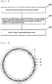
- FIG. 3 shows a cross-sectional view of the discharge portion of the nozzle, and the supply location of the thermoplastic polymer resin according to an embodiment of the present invention and air will be described in detail with reference to FIG. 3 .
- the position of the nozzle is expressed as “inlet portion”, “discharge portion”, and “distal end”, and the like.
- the “inlet portion” of a nozzle refers to the position where the nozzle starts, and the “discharge portion” of the nozzle refers to the position where the nozzle ends.
- the “distal end” of the nozzle means the position from the two-thirds location point of the nozzle to the discharge portion.
- the 0 location point of the nozzle is the inlet portion of the nozzle
- the 1 location point of the nozzle is the discharge portion of the nozzle.
- the cross-section perpendicular to the flow direction of the thermoplastic polymer resin and air is circular.
- the first spraying gas and the second spraying gas are supplied through a first gas stream 20 and the third spraying gas is supplied through a second gas stream 40.
- the thermoplastic polymer resin 30 is supplied together with the fourth spraying gas between the first gas stream 20 and the second gas stream 40.
- each supply stream (thermoplastic polymer resin and the fourth spraying gas stream 30, the first gas stream 20 and the second gas stream 40) is separated by a structure inside the nozzle. As specifically shown in FIG.
- thermoplastic polymer resin meets the fourth spraying gas 50 to form a thin film, and at this time, the fourth spraying gas 50 serves to spread the thermoplastic polymer resin thinly.
- the thermoplastic polymer resin flows down and first meets the first spraying gas 60 of the first gas stream, wherein the first spraying gas 60 serves to form droplets by breaking the filmed thermoplastic polymer resin.
- the thermoplastic polymer resin formed as a droplet preserves the amount of heat, while meeting the second spraying gas (70) of the first gas stream and the third spraying gas (80) of the second gas stream, and is discharged from the nozzle, and is not cooled until it enters the cooling chamber, so that a fibrous shape is not formed and the shape of the droplet is maintained.
- the second spraying gas 70 of the first gas stream and the third spraying gas 80 of the second gas stream also play an auxiliary role in breaking the thermoplastic polymer resin that has not yet been broken through the first spraying gas to form droplets, while preventing the droplets of the thermoplastic polymer resin from adhering to the discharge portion of the nozzle.
- the inside of the nozzle is adjusted to a suitable temperature for the thermoplastic polymer resin to be granulated. Since the rapid increase in temperature can change the structure of the thermoplastic polymer, the temperature from the extruder to the discharge portion of the nozzle can be increased step by step. Therefore, the internal temperature of the nozzle is set in a range higher than the internal temperature of the extruder on average. Since the temperature of the distal end of the nozzle is separately defined below, the internal temperature of the nozzle in this specification means the average temperature of the rest of the nozzle except for the distal end of the nozzle, unless otherwise specified. According to one embodiment of the present invention, the inside of the nozzle can be maintained at 250 to 350 °C.
- the internal temperature of the nozzle is less than 250 °C, it is not possible to transfer sufficient heat to satisfy the physical properties when granulating the thermoplastic polymer resin. If the internal temperature of the nozzle exceeds 350 °C, an excessive heat may be supplied to the thermoplastic polymer resin, thereby changing the structure of the thermoplastic polymer.
- the distal end of the nozzle can be maintained at a temperature higher than the average temperature inside the nozzle to improve the external and internal properties of the generated particles.
- B is less than 0.5, it is difficult to expect improvement of the external and internal physical properties of the particles according to the rise in the temperature of the distal end of the nozzle. If B is greater than 1.5, the heat transferred substantially from the distal end of the nozzle to the thermoplastic polymer is excessively increased, and thus the structure of the thermoplastic polymer may be deformed.
- the glass transition temperature and thermal decomposition temperature may vary depending on the type, polymerization degree, structure, and the like of the polymer. According to one embodiment of the present invention, since the distal end of the nozzle is maintained above the average temperature of the nozzle, additional heating means may be provided at the distal end of the nozzle, if desired.
- thermoplastic polymer particles discharged from the nozzle are supplied to the cooling chamber.
- the nozzle and the cooling chamber may be spaced apart from each other, and in this case, the discharged thermoplastic polymer particles are primarily cooled by ambient air before being supplied to the cooling chamber.
- the cooling chamber is positioned 0.1 to 1.0 m apart from the nozzle, specifically 0.15 to 0.4 m, more specifically 0.2 to 0.3 m apart.
- the separation distance is shorter than the distance, a large amount of high-temperature air is injected into the cooling chamber, and the cooling efficiency is low. If the separation distance is longer than the distance, the amount of cooling by the ambient air is increased, and thus rapid cooling by the cooling chamber cannot be achieved.
- the spraying angle may be 10 to 60°. When the thermoplastic polymer particles are discharged at the corresponding angle, the effect due to the separation between the nozzle and the cooling chamber can be doubled.
- the cooling chamber can cool the thermoplastic polymer particles by supplying low-temperature external air to the inside of the cooling chamber to contact the air and the thermoplastic polymer particles.
- the low-temperature external air forms a rotational airflow in the cooling chamber.
- the retention time of the thermoplastic polymer particles in the cooling chamber can be sufficiently secured by the rotational airflow.
- the flow rate of the external air supplied to the cooling chamber can be adjusted according to the supply amount of the thermoplastic polymer particles.
- the external air may be supplied to the cooling chamber at a flow rate of 1 to 10 m 3 /min.
- the cooling chamber has an internal temperature of 25 to 40 °C. In order to maintain this temperature, the external air may preferably have a temperature of -30 to -10 °C.
- the cooling chamber is provided with a plurality of the external air inlet, and the plurality of external air inlet may be installed so as not to interfere with the free-falling flow of the thermoplastic polymer particles.
- a plurality of external air inlets may be provided on the upper portion of the cooling chamber, and the external air inlet portion may be installed at 1/2 to 3/4 location points based on concentric circles of the cooling chamber.
- a plurality of external air inlets may be provided on the side surface of the cooling chamber, and the inflow velocity of the air of the external air inlet portion may be set to 0.5 to 10 m/s.
- thermoplastic polymer particles By supplying cryogenic external air, as compared to the thermoplastic polymer particles supplied to the cooling chamber, into the cooling chamber, the thermoplastic polymer particles are rapidly cooled so that the internal structure of the high temperature thermoplastic polymer particles can be properly maintained during discharging.
- the thermoplastic polymer particles are actually applied for the manufacture of products, they are reheated again. At this time, the reheated thermoplastic polymer particles have advantageous physical properties for processing.
- the polypropylene particles cooled by low-temperature external air are cooled to a temperature of 40 °C or less and discharged, and the discharged particles are collected through a cyclone or a bag filter.
- the particles can be collected by using a plurality of cyclones in series or in parallel.
- the plurality of cyclones can control the collection of the particles by different pressure conditions from each other.
- the present invention provides a nozzle for preparing thermoplastic polymer particles comprising an input portion into which a thermoplastic polymer resin is injected and a discharge portion from which the thermoplastic polymer resin is sprayed, wherein the input portion and the discharge portion of the nozzle are connected by a plurality of flow paths.
- thermoplastic polymer particles The specific contents of the nozzle for preparing the thermoplastic polymer particles are the same as the nozzle used in the preparation method of the thermoplastic polymer particles, as discussed above.
- the twin screw extruder was designed to raise the extruder temperature from 140 °C to 150 °C from the fore-end of the extruder to the 2/10 location point, raise the extruder temperature from 150 °C to 200 °C from the 2/10 location point to the 7/10 location point, and raise the extruder temperature from 200 °C to 225 °C from the 7/10 location point to the distal end, and the extrusion was carried out by setting the condition of an extrusion amount of about 15 kg/hr.
- nitrogen gas at a flow rate of 16 L/min was injected into the start portion of the extruder in the extruder, and then allowed to exit from the end portion of the extruder.
- the extruded polypropylene resin was passed through a mesh screen having 80 mesh.
- the extruded polypropylene resin has a viscosity of about 10 Pa ⁇ s, and the extruded polypropylene resin was supplied to a nozzle having a ratio (A/B) of the area (A) of the discharge portion from which the resin is sprayed and the area (B) of the input portion into which the resin is injected set to 20 and including a plurality of flow paths therein, and the resin was made to have a retention time of 30 seconds.
- the nozzle was set at an internal temperature of about 300 °C and a distal end temperature of about 400 °C (B value according to Calculation Formula 5 is about 1.34).
- the nozzle included 32 flow paths based on Calculation Formula 4 (X value according to Calculation Formula 4 is 9.2).
- the first spraying gas that sprays nitrogen gas at about 470 °C at a flow rate of 150m/s at an angle of 45° based on the discharging direction of the polymer resin discharged from the discharge portion of the nozzle
- the second spraying gas that sprays at an angle of 75° based on the discharging direction of the polymer resin discharged from the discharge portion at the same temperature and flow rate as the first spraying gas
- the third spraying gas that sprays at an angle of 7.5° based on the discharging direction of the polymer resin discharged from the discharge portion at a temperature 25 °C higher than the first spraying gas and at the same flow rate as the first spraying gas
- the fourth spraying gas that sprays in parallel based on the discharging direction of the polymer resin discharged from the discharge portion at a temperature 10 °C higher than the first spraying gas and at the same flow rate as the first spraying
- the polypropylene resin supplied to the nozzle was atomized by contact with the spraying gases, and the atomized particles were sprayed from the nozzle.
- the cooling chamber was provided with an external air inlet portion which is configured to form a rotating airflow by injecting -25°C air at a flow rate of about 6 m 3 /min before the sprayed particles are supplied.
- the external air inlet portion was installed at 3/4 location point based on concentric circles on the top of the cooling chamber.
- the particles cooled sufficiently to 40 °C or less in the cooling chamber were collected through two cyclones connected in series.
- thermoplastic polyurethane resin Librizol, LZM-TPU-95A, Mw: about 100,000 g/mol, glass transition temperature (T g ): about -19 °C, thermal decomposition temperature (T d ): about 330°C
- T g glass transition temperature
- T d thermal decomposition temperature
- the twin screw extruder was designed to raise the extruder temperature from 160 °C to 170 °C from the fore-end of the extruder to the 2/10 location point, raise the extruder temperature from 170 °C to 210 °C from the 2/10 location point to the 7/10 location point, and raise the extruder temperature from 210 °C to 220 °C from the 7/10 location point to the distal end, and the extrusion was carried out by setting the condition of an extrusion amount of about 15 kg/hr.
- nitrogen gas at a flow rate of 16 L/min was injected into the start portion of the extruder in the extruder, and then allowed to exit from the end portion of the extruder.
- the extruded thermoplastic polyurethane resin was passed through a mesh screen having 80 mesh.
- the extruded thermoplastic polyurethane resin has a viscosity of about 5 Pa ⁇ s, and the extruded thermoplastic polyurethane resin was supplied to a nozzle having a ratio (A/B) of the area (A) of the discharge portion from which the resin is sprayed and the area (B) of the input portion into which the resin is injected set to 20 and including a plurality of flow paths therein, and the resin was made to have a retention time of 30 seconds.
- the nozzle was set at an internal temperature of about 280 °C and a distal end temperature of about 335 °C (B value according to Calculation Formula 5 is about 1.01).
- the nozzle included 32 flow paths based on Calculation Formula 4.
- the first spraying gas that sprays nitrogen gas at about 340 °C at a flow rate of 150 m/s at an angle of 45° based on the discharging direction of the polymer resin discharged from the discharge portion of the nozzle
- the second spraying gas that sprays at an angle of 75° based on the discharging direction of the polymer resin discharged from the discharge portion at the same temperature and flow rate as the first spraying gas
- the third spraying gas that sprays at an angle of 7.5° based on the discharging direction of the polymer resin discharged from the discharge portion at a temperature 25 °C higher than the first spraying gas and at the same flow rate as the first spraying gas
- the fourth spraying gas that sprays in parallel based on the discharging direction of the polymer resin discharged from the discharge portion at a temperature 10 °C higher than the first spraying gas and at the same flow rate as the first spraying gas were sprayed.
- thermoplastic polyurethane resin supplied to the nozzle was atomized by contact with the spraying gases, and the atomized particles were sprayed from the nozzle.
- the cooling chamber was provided with an external air inlet portion which is configured to form a rotating airflow by injecting -25°C air at a flow rate of about 6 m 3 /min before the sprayed particles are supplied.
- the external air inlet portion was installed at 3/4 location point based on concentric circles on the top of the cooling chamber.
- the particles cooled sufficiently to 40 °C or less in the cooling chamber were collected through two cyclones connected in series.
- the twin screw extruder was designed to raise the extruder temperature from 150 °C to 160 °C from the fore-end of the extruder to the 2/10 location point, raise the extruder temperature from 160 °C to 190 °C from the 2/10 location point to the 7/10 location point, and raise the extruder temperature from 190 °C to 200 °C from the 7/10 location point to the distal end, and the extrusion was carried out by setting the condition of an extrusion amount of about 15 kg/hr.
- nitrogen gas at a flow rate of 16 L/min was injected into the start portion of the extruder in the extruder, and then allowed to exit from the end portion of the extruder.
- the extruded polylactic acid resin was passed through a mesh screen having 80 mesh.
- the extruded polylactic acid resin has a viscosity of about 10 Pa ⁇ s, and the extruded polylactic acid resin was supplied to a nozzle having a ratio (A/B) of the area (A) of the discharge portion from which the resin is sprayed and the area (B) of the input portion into which the resin is injected set to 20 and including a plurality of flow paths therein, and the resin was made to have a retention time of 30 seconds.
- the nozzle was set at an internal temperature of about 300 °C and a distal end temperature of about 400 °C (B value according to Calculation Formula 5 is about 0.82).
- the nozzle included 32 flow paths based on Calculation Formula 4.
- the first spraying gas that sprays nitrogen gas at about 420 °C at a flow rate of 150 m/s at an angle of 45° based on the discharging direction of the polymer resin discharged from the discharge portion of the nozzle
- the second spraying gas that sprays at an angle of 75° based on the discharging direction of the polymer resin discharged from the discharge portion at the same temperature and flow rate as the first spraying gas
- the third spraying gas that sprays at an angle of 7.5° based on the discharging direction of the polymer resin discharged from the discharge portion at a temperature 25 °C higher than the first spraying gas and at the same flow rate as the first spraying gas
- the fourth spraying gas that sprays in parallel based on the discharging direction of the polymer resin discharged from the discharge portion at a temperature 10 °C higher than the first spraying gas and at the same flow rate as the first spraying gas were sprayed.
- the polylactic acid resin supplied to the nozzle was atomized by contact with the spraying gases, and the atomized particles were sprayed from the nozzle.
- the cooling chamber was provided with an external air inlet portion which is configured to form a rotating airflow by injecting -25°C air at a flow rate of about 6 m 3 /min before the sprayed particles are supplied.
- the external air inlet portion was installed at 3/4 location point based on concentric circles on the top of the cooling chamber.
- the particles cooled sufficiently to 40 °C or less in the cooling chamber were collected through two cyclones connected in series.
- the twin screw extruder was designed to raise the extruder temperature from 240 °C to 250 °C from the fore-end of the extruder to the 2/10 location point, raise the extruder temperature from 250 °C to 300 °C from the 2/10 location point to the 7/10 location point, and raise the extruder temperature from 300 °C to 320 °C from the 7/10 location point to the distal end, and the extrusion was carried out by setting the condition of an extrusion amount of about 15 kg/hr.
- nitrogen gas at a flow rate of 16 L/min was injected into the start portion of the extruder in the extruder, and then allowed to exit from the end portion of the extruder.
- the extruded polyamide resin was passed through a mesh screen having 80 mesh.
- the extruded polyamide resin has a viscosity of about 20 Pa ⁇ s, and the extruded polyamide resin was supplied to a nozzle having a ratio (A/B) of the area (A) of the discharge portion from which the resin is sprayed and the area (B) of the input portion into which the resin is injected set to 20 and including a plurality of flow paths therein, and the resin was made to have a retention time of 30 seconds.
- the nozzle was set at an internal temperature of about 430 °C and a distal end temperature of about 470 °C (B value according to Calculation Formula 5 is about 1.05).
- the nozzle included 32 flow paths based on Calculation Formula 4.
- the first spraying gas that sprays nitrogen gas at about 550 °C at a flow rate of 150 m/s at an angle of 45° based on the discharging direction of the polymer resin discharged from the discharge portion of the nozzle
- the second spraying gas that sprays at an angle of 75° based on the discharging direction of the polymer resin discharged from the discharge portion at the same temperature and flow rate as the first spraying gas
- the third spraying gas that sprays at an angle of 7.5° based on the discharging direction of the polymer resin discharged from the discharge portion at a temperature 25 °C higher than the first spraying gas and at the same flow rate as the first spraying gas
- the fourth spraying gas that sprays in parallel based on the discharging direction of the polymer resin discharged from the discharge portion at a temperature 10 °C higher than the first spraying gas and at the same flow rate as the first spraying gas were sprayed.
- the polyamide resin supplied to the nozzle was atomized by contact with the spraying gases, and the atomized particles were sprayed from the nozzle.
- the cooling chamber was provided with an external air inlet portion which is configured to form a rotating airflow by injecting -25°C air at a flow rate of about 6 m 3 /min before the sprayed particles are supplied.
- the external air inlet portion was installed at 3/4 location point based on concentric circles on the top of the cooling chamber.
- the particles cooled sufficiently to 40 °C or less in the cooling chamber were collected through two cyclones connected in series.
- the twin screw extruder was designed to raise the extruder temperature from 370 °C to 380 °C from the fore-end of the extruder to the 2/10 location point, raise the extruder temperature from 380 °C to 400 °C from the 2/10 location point to the 7/10 location point, and raise the extruder temperature from 400 °C to 420 °C from the 7/10 location point to the distal end, and the extrusion was carried out by setting the condition of an extrusion amount of about 15 kg/hr.
- nitrogen gas at a flow rate of 16 L/min was injected into the start portion of the extruder in the extruder, and then allowed to exit from the end portion of the extruder.
- the extruded polyether sulfone resin was passed through a mesh screen having 80 mesh.
- the extruded polyether sulfone resin has a viscosity of about 20 Pa ⁇ s, and the extruded polyether sulfone resin was supplied to a nozzle having a ratio (A/B) of the area (A) of the discharge portion from which the resin is sprayed and the area (B) of the input portion into which the resin is injected set to 20 and including a plurality of flow paths therein, and the resin was made to have a retention time of 30 seconds.
- the nozzle was set at an internal temperature of about 440 °C and a distal end temperature of about 480 °C (B value according to Calculation Formula 5 is about 1.08).
- the nozzle included 32 flow paths based on Calculation Formula 4.
- the first spraying gas that sprays nitrogen gas at about 580 °C at a flow rate of 150 m/s at an angle of 45° based on the discharging direction of the polymer resin discharged from the discharge portion of the nozzle
- the second spraying gas that sprays at an angle of 75° based on the discharging direction of the polymer resin discharged from the discharge portion at the same temperature and flow rate as the first spraying gas
- the third spraying gas that sprays at an angle of 7.5° based on the discharging direction of the polymer resin discharged from the discharge portion at a temperature 25 °C higher than the first spraying gas and at the same flow rate as the first spraying gas
- the fourth spraying gas that sprays in parallel based on the discharging direction of the polymer resin discharged from the discharge portion at a temperature 10 °C higher than the first spraying gas and at the same flow rate as the first spraying gas were sprayed.
- the polyether sulfone resin supplied to the nozzle was atomized by contact with the spraying gases, and the atomized particles were sprayed from the nozzle.
- the cooling chamber was provided with an external air inlet portion which is configured to form a rotating airflow by injecting -25°C air at a flow rate of about 6 m 3 /min before the sprayed particles are supplied.
- the external air inlet portion was installed at 3/4 location point based on concentric circles on the top of the cooling chamber.
- the particles cooled sufficiently to 40 °C or less in the cooling chamber were collected through two cyclones connected in series.
- Polymer particles were prepared in the same manner as Example 1, except that only the first spraying gas that sprays at an angle of 45° based on the discharging direction of the polymer resin discharged from the discharge portion of the nozzle was sprayed, and the second spraying gas to the fourth spraying gas were not sprayed.
- Polymer particles were prepared in the same manner as Example 1, except that the twin screw extruder was set to raise the extruder temperature from 130 °C to 140 °C from the fore-end of the extruder to the 2/10 location point, raise the extruder temperature from 140 °C to 170 °C from the 2/10 location point to the 7/10 location point, and raise the extruder temperature from 170 °C to 200 °C from the 7/10 location point to the distal end.
- Polymer particles were prepared in the same manner as Example 1, except that the polymer resin did not pass through the mesh screen.
- Polymer particles were prepared in the same manner as Example 1, except that the nozzle having a ratio (A/B) of the area (A) of the discharge portion from which the resin is sprayed and the area (B) of the input portion into which the resin is injected set to 35 was used.
- Polymer particles were prepared in the same manner as Example 1, except that the nozzle comprising 4 flow paths based on Calculation Formula 4 (X value according to Calculation Formula 4 is 9.2) was used.
- Polymer particles were prepared in the same manner as in Example 1, except that nitrogen gas was not injected into the extruder.
- Polymer particles were prepared in the same manner as in Example 1, except that general air instead of nitrogen gas was sprayed onto the polymer resin discharged from the discharge portion.
- Polymer particles were prepared in the same manner as Example 2, except that only the first spraying gas that sprays at an angle of 45° based on the discharging direction of the polymer resin discharged from the discharge portion of the nozzle was sprayed, and the second spraying gas to the fourth spraying gas were not sprayed.
- Polymer particles were prepared in the same manner as Example 2, except that the twin screw extruder was set to raise the extruder temperature from 140 °C to 150 °C from the fore-end of the extruder to the 2/10 location point, raise the extruder temperature from 150 °C to 180 °C from the 2/10 location point to the 7/10 location point, and raise the extruder temperature from 180 °C to 200 °C from the 7/10 location point to the distal end.
- Polymer particles were prepared in the same manner as Example 2, except that the polymer resin did not pass through the mesh screen.
- Polymer particles were prepared in the same manner as Example 2, except that the nozzle having a ratio (A/B) of the area (A) of the discharge portion from which the resin is sprayed and the area (B) of the input portion into which the resin is injected set to 35 was used.
- Polymer particles were prepared in the same manner as Example 2, except that the nozzle comprising 4 flow paths based on Calculation Formula 4 (X value according to Calculation Formula 4 is 9.2) was used.
- Polymer particles were prepared in the same manner as in Example 2, except that nitrogen gas was not injected into the extruder.
- Polymer particles were prepared in the same manner as in Example 2, except that general air instead of nitrogen gas was sprayed onto the polymer resin discharged from the discharge portion.
- Polymer particles were prepared in the same manner as Example 3, except that only the first spraying gas that sprays at an angle of 45° based on the discharging direction of the polymer resin discharged from the discharge portion of the nozzle was sprayed, and the second spraying gas to the fourth spraying gas were not sprayed.
- Polymer particles were prepared in the same manner as Example 3, except that the twin screw extruder was set to raise the extruder temperature from 140 °C to 150 °C from the fore-end of the extruder to the 2/10 location point, raise the extruder temperature from 150 °C to 170 °C from the 2/10 location point to the 7/10 location point, and raise the extruder temperature from 170 °C to 180 °C from the 7/10 location point to the distal end.
- Polymer particles were prepared in the same manner as Example 3, except that the polymer resin did not pass through the mesh screen.
- Polymer particles were prepared in the same manner as Example 3, except that the nozzle having a ratio (A/B) of the area (A) of the discharge portion from which the resin is sprayed and the area (B) of the input portion into which the resin is injected set to 35 was used.
- Polymer particles were prepared in the same manner as Example 3, except that the nozzle comprising 4 flow paths based on Calculation Formula 4 (X value according to Calculation Formula 4 is 9.2) was used.
- Polymer particles were prepared in the same manner as in Example 3, except that nitrogen gas was not injected into the extruder.
- Polymer particles were prepared in the same manner as in Example 3, except that general air instead of nitrogen gas was sprayed onto the polymer resin discharged from the discharge portion.
- Polymer particles were prepared in the same manner as Example 4, except that only the first spraying gas that sprays at an angle of 45° based on the discharging direction of the polymer resin discharged from the discharge portion of the nozzle was sprayed, and the second spraying gas to the fourth spraying gas were not sprayed.
- Polymer particles were prepared in the same manner as Example 4, except that the twin screw extruder was set to raise the extruder temperature from 230 °C to 240 °C from the fore-end of the extruder to the 2/10 location point, raise the extruder temperature from 240 °C to 280 °C from the 2/10 location point to the 7/10 location point, and raise the extruder temperature from 280 °C to 300 °C from the 7/10 location point to the distal end.
- Polymer particles were prepared in the same manner as Example 4, except that the polymer resin did not pass through the mesh screen.
- Polymer particles were prepared in the same manner as Example 4, except that the nozzle having a ratio (A/B) of the area (A) of the discharge portion from which the resin is sprayed and the area (B) of the input portion into which the resin is injected set to 35 was used.
- Polymer particles were prepared in the same manner as Example 4, except that the nozzle comprising 4 flow paths based on Calculation Formula 4 (X value according to Calculation Formula 4 is 9.2) was used.
- Polymer particles were prepared in the same manner as in Example 4, except that nitrogen gas was not injected into the extruder.
- Polymer particles were prepared in the same manner as in Example 4, except that general air instead of nitrogen gas was sprayed onto the polymer resin discharged from the discharge portion.
- Polymer particles were prepared in the same manner as Example 5, except that only the first spraying gas that sprays at an angle of 45° based on the discharging direction of the polymer resin discharged from the discharge portion of the nozzle was sprayed, and the second spraying gas to the fourth spraying gas were not sprayed.
- Polymer particles were prepared in the same manner as Example 5, except that the twin screw extruder was set to raise the extruder temperature from 360 °C to 370 °C from the fore-end of the extruder to the 2/10 location point, raise the extruder temperature from 370 °C to 390 °C from the 2/10 location point to the 7/10 location point, and raise the extruder temperature from 390 °C to 400 °C from the 7/10 location point to the distal end.
- Polymer particles were prepared in the same manner as Example 5, except that the polymer resin did not pass through the mesh screen.
- Polymer particles were prepared in the same manner as Example 5, except that the nozzle having a ratio (A/B) of the area (A) of the discharge portion from which the resin is sprayed and the area (B) of the input portion into which the resin is injected set to 35 was used.
- Polymer particles were prepared in the same manner as Example 5, except that the nozzle comprising 4 flow paths based on Calculation Formula 4 (X value according to Calculation Formula 4 is 9.2) was used.
- Polymer particles were prepared in the same manner as in Example 5, except that nitrogen gas was not injected into the extruder.
- Polymer particles were prepared in the same manner as in Example 5, except that general air instead of nitrogen gas was sprayed onto the polymer resin discharged from the discharge portion.
- the particle size distribution of the polymer resin particles prepared according to Examples 1 to 5 and Comparative Examples 1-1 to 5-5 was measured in the following manner, and the results are shown in Tables 1 to 2 below. Specifically, for particle size distribution of Example 3 and Comparative Examples 3-1 to 3-5, sample pretreatment was performed in the following 1-2) manner, and for all Examples except for Example 3 and all Comparative examples except for Comparative examples 3-1 to 3-5, sample pretreatment was performed in the manner 1-1). After that, particle-size distribution was measured by method 2).
- Sample pretreatment A powder sample is placed in ethanol in an amount of about 0.003 wt%, and a 50 Watt/30 kHz ultrasonic disperser is set to 30% of the maximum amplitude, and the powder sample is dispersed in ethanol by excitation of ultrasonic waves for about 120 seconds.
- Sample pretreatment About 0.003 wt% of a powder sample is added to distilled water to which 0.1 wt% of PEO/PPO ethylene derivative as a dispersant has been added, and a 50 Watt/30 kHz ultrasonic disperser is set to 30% of the maximum amplitude, and the powder sample is dispersed in the distilled water by excitation of ultrasonic waves for about 120 seconds.
- the particle diameter of the particles prepared according to Example 1 was 25 to 30 ⁇ m smaller than the D 90 average particle diameter, unlike the particle diameter of the particles prepared according to Comparative examples 1-1 to 1-5.
- the particle diameters of the particles prepared according to Examples 2 to 5 also show the same trend as described above.
- the particles have the same particle diameter distribution as the particles prepared according to Examples 1 to 5, when applied to products, it can effectively compensate for the shortcomings of the case that only controls the average particle diameter.
- Example 1 and Comparative examples 1-6 and 1-7 a sample pretreatment was performed in the manner of 1-1), for Example 3 and Comparative examples 3-6 and 3-7, a sample pretreatment was performed in the manner of 1-2), and for the remaining Examples and Comparative examples except for Example 1 and Example 3, Comparative examples 1-6 and 1-7, and Comparative examples 3-6 and 3-7, a sample pretreatment was performed in the manner of 1-3).
- Example 1 and Comparative examples 1-6 and 1-7 the weight average molecular weight was measured using a high-temperature GPC instrument, and for Examples 2 to 5 and Comparative Examples 2-6 to 5-7, the weight average molecular weight was measured using a general GPC instrument, and the results are described in Table 3 below.
- the B * value is an indicator that expresses the degree of yellow and blue in the color measurement of the object, and it means that the larger the + value, the more yellow, and the larger the - value, the closer the blue color.
- the powder was added, and pressed at 1 bar for one minute and at 7 bar for three minutes at room temperature using a powder press machine to prepare a sample for B * measurement, and then B * was measured using a portable color-difference meter called the Spectro-guide of BYK Gardner company, and the results are described in Table 3 below.
- the particles of Comparative example 1-6 do not have a large change in molecular weight compared to Example 1, which means that atomizing the polymer resin discharged from the discharge portion of the nozzle by spraying nitrogen gas, rather than introducing nitrogen into the extruder, is more effective in preventing the decrease in molecular weight.
- the particles of Comparative example 1-7 caused a color change compared to the particles of Example 1.
- Comparative example 1-6 do not have a large change in b* value compared to Example 1, which means that atomizing the polymer resin discharged from the discharge portion of the nozzle by spraying nitrogen gas, rather than introducing nitrogen into the extruder, is more effective in minimizing yellowing.
- the particles prepared according to Examples 2 to 5 and the particles prepared according to Comparative examples 2-6 and 2-7, 3-6 and 3-7, 4-6 and 4-7 and 5-6 and 5-7 also showed the same tendency as described above.
Landscapes
- Chemical & Material Sciences (AREA)
- Health & Medical Sciences (AREA)
- Chemical Kinetics & Catalysis (AREA)
- Medicinal Chemistry (AREA)
- Polymers & Plastics (AREA)
- Organic Chemistry (AREA)
- Engineering & Computer Science (AREA)
- Mechanical Engineering (AREA)
- Processes Of Treating Macromolecular Substances (AREA)
- Processing And Handling Of Plastics And Other Materials For Molding In General (AREA)
Applications Claiming Priority (2)
| Application Number | Priority Date | Filing Date | Title |
|---|---|---|---|
| KR1020190112897A KR102614368B1 (ko) | 2019-09-11 | 2019-09-11 | 열가소성 고분자 입자 및 이의 제조방법 |
| PCT/KR2020/012291 WO2021049901A1 (ko) | 2019-09-11 | 2020-09-11 | 열가소성 고분자 입자 및 이의 제조방법 |
Publications (2)
| Publication Number | Publication Date |
|---|---|
| EP4029902A1 true EP4029902A1 (de) | 2022-07-20 |
| EP4029902A4 EP4029902A4 (de) | 2023-10-04 |
Family
ID=74866785
Family Applications (1)
| Application Number | Title | Priority Date | Filing Date |
|---|---|---|---|
| EP20862372.8A Withdrawn EP4029902A4 (de) | 2019-09-11 | 2020-09-11 | Thermoplastische polymerteilchen und verfahren zu ihrer herstellung |
Country Status (5)
| Country | Link |
|---|---|
| US (1) | US20220340720A1 (de) |
| EP (1) | EP4029902A4 (de) |
| JP (1) | JP7350417B2 (de) |
| KR (1) | KR102614368B1 (de) |
| WO (1) | WO2021049901A1 (de) |
Cited By (1)
| Publication number | Priority date | Publication date | Assignee | Title |
|---|---|---|---|---|
| EP4029903A4 (de) * | 2019-09-11 | 2023-10-04 | LX Hausys, Ltd. | Thermoplastische polymerteilchen und verfahren zur herstellung davon |
Family Cites Families (26)
| Publication number | Priority date | Publication date | Assignee | Title |
|---|---|---|---|---|
| JPS59172521A (ja) * | 1983-03-23 | 1984-09-29 | Mitsubishi Chem Ind Ltd | 真球状ポリオレフイン微粒子の製造法 |
| JPH05117407A (ja) * | 1991-10-29 | 1993-05-14 | Dainippon Ink & Chem Inc | ポリウレタン樹脂スラリーの製造方法及びポリウレタン樹脂粉末の製造方法 |
| DE4319990A1 (de) * | 1993-06-17 | 1994-12-22 | Messer Griesheim Gmbh | Verfahren zum Herstellen von Teilchen aus Kunststoffen |
| FR2738179B1 (fr) * | 1995-09-01 | 1997-10-03 | Bp Chemicals Snc | Procede pour extruder un polyethylene |
| CA2297102A1 (en) | 1997-08-01 | 1999-02-11 | Huntsman Corporation | Expandable thermoplastic particles and atomization method for making same |
| JP3861500B2 (ja) | 1998-04-23 | 2006-12-20 | 大日本インキ化学工業株式会社 | 生分解性ポリエステルからなる自己水分散性粒子の製法 |
| JP2000052341A (ja) * | 1998-08-05 | 2000-02-22 | Nippon Pneumatic Mfg Co Ltd | 球形化処理装置における原料供給装置 |
| JP4635292B2 (ja) | 2000-04-04 | 2011-02-23 | 東レ株式会社 | ポリ乳酸系樹脂粉末およびその製法、並びにそれによって得られる接着剤 |
| DE10205897A1 (de) | 2002-02-13 | 2003-08-21 | Mepura Metallpulver | Verfahren zur Herstellung von partikelförmigem Material |
| US20030190472A1 (en) | 2002-04-03 | 2003-10-09 | 3D Systems, Inc. | Thermoplastic polymer filled pastes |
| JP4118741B2 (ja) | 2002-08-22 | 2008-07-16 | 旭化成ケミカルズ株式会社 | 新規な樹脂組成物の製造方法及びその樹脂組成物 |
| JP2004269865A (ja) | 2003-02-17 | 2004-09-30 | Daicel Chem Ind Ltd | 生分解性樹脂粒子の製造方法 |
| JP2006273930A (ja) * | 2005-03-28 | 2006-10-12 | Teijin Engineering Ltd | 機能性粒子担持粒状成形体とその製造方法 |
| JP2012140488A (ja) | 2010-12-28 | 2012-07-26 | Asahi Kasei Chemicals Corp | 脂肪族ポリヒドロキシカルボン酸結晶化物の製造方法及びそれにより得られるペレット |
| US9321207B2 (en) * | 2012-03-06 | 2016-04-26 | Wisconsin Alumni Research Foundation | Method and apparatus for micropelletization |
| EP2897719A2 (de) * | 2012-09-21 | 2015-07-29 | President and Fellows of Harvard College | Systeme und verfahren zur sprühtrocknung in mikrofluidischen und anderen systemen |
| BR112015024868A2 (pt) * | 2013-03-28 | 2017-07-18 | Instillo Gmbh | método para produzir dispersões e matérias sólidas através de precipitação, coprecipitação e processo de auto-organização controlados e método para produzir dispersões e matérias sólidas através de precipitação controlada, coprecipitação e processo de auto-organização em um reator de microjato |
| KR20150078004A (ko) * | 2013-12-30 | 2015-07-08 | 도레이케미칼 주식회사 | 기계적 강도 및 발포율이 향상된 미세기공 열가소성 고분자 수지 발포체 및 이의 제조방법 |
| KR20150126517A (ko) * | 2014-05-02 | 2015-11-12 | (주)엘지하우시스 | 고속 건식 함침용 미세 입자, 이를 포함하는 열가소성 복합재 및 이의 제조방법 |
| KR101991686B1 (ko) * | 2014-09-30 | 2019-10-01 | (주)엘지하우시스 | 열가소성 엘라스토머 수지 분말 및 열가소성 엘라스토머 수지 분말의 제조 방법 |
| FR3027024B1 (fr) | 2014-10-09 | 2016-11-25 | Roquette Freres | Procede de preparation de granules de polyurethane thermoplastique |
| CN106140038B (zh) * | 2015-04-08 | 2019-07-12 | 通用电气公司 | 制备聚合物微粒的方法和装置 |
| CN108699255A (zh) | 2016-05-10 | 2018-10-23 | 株式会社吴羽 | 聚酰胺微粒及其制造方法以及聚酰胺微粒组合物 |
| KR102231131B1 (ko) * | 2017-03-09 | 2021-03-23 | (주)엘지하우시스 | 열가소성 고분자 입자의 제조방법 |
| KR20180103666A (ko) * | 2017-03-09 | 2018-09-19 | (주)엘지하우시스 | 열가소성 폴리우레탄 시트 및 이의 제조방법 |
| KR20190112897A (ko) | 2018-03-27 | 2019-10-08 | 비나텍주식회사 | 다리튬계산화물을 함유하는 양극 및 그를 포함하는 리튬이온 커패시터 |
-
2019
- 2019-09-11 KR KR1020190112897A patent/KR102614368B1/ko active Active
-
2020
- 2020-09-11 US US17/641,915 patent/US20220340720A1/en not_active Abandoned
- 2020-09-11 WO PCT/KR2020/012291 patent/WO2021049901A1/ko not_active Ceased
- 2020-09-11 EP EP20862372.8A patent/EP4029902A4/de not_active Withdrawn
- 2020-09-11 JP JP2022515899A patent/JP7350417B2/ja active Active
Cited By (1)
| Publication number | Priority date | Publication date | Assignee | Title |
|---|---|---|---|---|
| EP4029903A4 (de) * | 2019-09-11 | 2023-10-04 | LX Hausys, Ltd. | Thermoplastische polymerteilchen und verfahren zur herstellung davon |
Also Published As
| Publication number | Publication date |
|---|---|
| WO2021049901A1 (ko) | 2021-03-18 |
| JP7350417B2 (ja) | 2023-09-26 |
| KR20210031209A (ko) | 2021-03-19 |
| KR102614368B1 (ko) | 2023-12-14 |
| EP4029902A4 (de) | 2023-10-04 |
| US20220340720A1 (en) | 2022-10-27 |
| JP2022547683A (ja) | 2022-11-15 |
Similar Documents
| Publication | Publication Date | Title |
|---|---|---|
| EP1853651B1 (de) | Polyethylenformzusammensetzung zur herstellung von blasfolien mit verbesserter verarbeitbarkeit | |
| EP3648939B1 (de) | Verfahren zur herstellung einer polyolefinzusammensetzung | |
| KR102259634B1 (ko) | 열가소성 폴리우레탄 시트 및 이의 제조방법 | |
| EP1853662B1 (de) | Polyethylenformmasse zur herstellung von blasfolien mit verbesserten mechanischen eigenschaften und verbesserter verarbeitbarkeit | |
| EP1853650A1 (de) | Polyethylenformmasse zur herstellung von blasfolien mit verbesserten mechanischen eigenschaften | |
| EP4029902A1 (de) | Thermoplastische polymerteilchen und verfahren zu ihrer herstellung | |
| EP4029903A1 (de) | Thermoplastische polymerteilchen und verfahren zur herstellung davon | |
| KR102294373B1 (ko) | 폴리락트산 입자 및 이의 제조방법 | |
| KR20180103751A (ko) | 열가소성 고분자 입자의 제조방법 | |
| JP7354433B2 (ja) | ポリプロピレン粒子、この製造方法、これを使用して製造されたバイポーラプレート及びこれを含むレドックスフロー電池 | |
| KR102259633B1 (ko) | 열가소성 폴리우레탄 입자 및 이의 제조방법 | |
| KR20200028863A (ko) | 열가소성 폴리우레탄 입자 및 이의 제조방법 | |
| JPS59172521A (ja) | 真球状ポリオレフイン微粒子の製造法 |
Legal Events
| Date | Code | Title | Description |
|---|---|---|---|
| STAA | Information on the status of an ep patent application or granted ep patent |
Free format text: STATUS: THE INTERNATIONAL PUBLICATION HAS BEEN MADE |
|
| PUAI | Public reference made under article 153(3) epc to a published international application that has entered the european phase |
Free format text: ORIGINAL CODE: 0009012 |
|
| STAA | Information on the status of an ep patent application or granted ep patent |
Free format text: STATUS: REQUEST FOR EXAMINATION WAS MADE |
|
| 17P | Request for examination filed |
Effective date: 20220308 |
|
| AK | Designated contracting states |
Kind code of ref document: A1 Designated state(s): AL AT BE BG CH CY CZ DE DK EE ES FI FR GB GR HR HU IE IS IT LI LT LU LV MC MK MT NL NO PL PT RO RS SE SI SK SM TR |
|
| DAV | Request for validation of the european patent (deleted) | ||
| DAX | Request for extension of the european patent (deleted) | ||
| A4 | Supplementary search report drawn up and despatched |
Effective date: 20230901 |
|
| RIC1 | Information provided on ipc code assigned before grant |
Ipc: B29B 7/48 20060101ALI20230828BHEP Ipc: B29B 7/72 20060101ALI20230828BHEP Ipc: C08L 77/02 20060101ALI20230828BHEP Ipc: B29B 9/16 20060101ALI20230828BHEP Ipc: B29B 9/12 20060101ALI20230828BHEP Ipc: B29B 9/10 20060101ALI20230828BHEP Ipc: B29B 7/82 20060101ALI20230828BHEP Ipc: B29B 11/14 20060101ALI20230828BHEP Ipc: C08L 77/00 20060101ALI20230828BHEP Ipc: C08L 67/04 20060101ALI20230828BHEP Ipc: C08J 3/12 20060101AFI20230828BHEP |
|
| STAA | Information on the status of an ep patent application or granted ep patent |
Free format text: STATUS: THE APPLICATION IS DEEMED TO BE WITHDRAWN |
|
| 18D | Application deemed to be withdrawn |
Effective date: 20240403 |