EP4029809B1 - Ceiling transport vehicle - Google Patents
Ceiling transport vehicle Download PDFInfo
- Publication number
- EP4029809B1 EP4029809B1 EP20862790.1A EP20862790A EP4029809B1 EP 4029809 B1 EP4029809 B1 EP 4029809B1 EP 20862790 A EP20862790 A EP 20862790A EP 4029809 B1 EP4029809 B1 EP 4029809B1
- Authority
- EP
- European Patent Office
- Prior art keywords
- base
- lock mechanism
- transport vehicle
- elevator
- state
- Prior art date
- Legal status (The legal status is an assumption and is not a legal conclusion. Google has not performed a legal analysis and makes no representation as to the accuracy of the status listed.)
- Active
Links
- 230000007246 mechanism Effects 0.000 claims description 132
- 239000000725 suspension Substances 0.000 claims description 128
- 210000000078 claw Anatomy 0.000 claims description 26
- 230000003028 elevating effect Effects 0.000 claims description 12
- 230000008878 coupling Effects 0.000 description 17
- 238000010168 coupling process Methods 0.000 description 17
- 238000005859 coupling reaction Methods 0.000 description 17
- 238000003780 insertion Methods 0.000 description 8
- 230000037431 insertion Effects 0.000 description 8
- 230000006835 compression Effects 0.000 description 7
- 238000007906 compression Methods 0.000 description 7
- 229920006311 Urethane elastomer Polymers 0.000 description 4
- 230000001174 ascending effect Effects 0.000 description 4
- 230000008901 benefit Effects 0.000 description 3
- 230000006870 function Effects 0.000 description 3
- 230000035939 shock Effects 0.000 description 3
- 238000004804 winding Methods 0.000 description 3
- 230000001133 acceleration Effects 0.000 description 2
- 238000006243 chemical reaction Methods 0.000 description 2
- 230000000694 effects Effects 0.000 description 2
- 230000005284 excitation Effects 0.000 description 2
- 239000000463 material Substances 0.000 description 2
- 238000005096 rolling process Methods 0.000 description 2
- 238000010586 diagram Methods 0.000 description 1
- 229920005989 resin Polymers 0.000 description 1
- 239000011347 resin Substances 0.000 description 1
- 230000000630 rising effect Effects 0.000 description 1
- 239000011435 rock Substances 0.000 description 1
- 239000004065 semiconductor Substances 0.000 description 1
- 229920002050 silicone resin Polymers 0.000 description 1
- 230000001629 suppression Effects 0.000 description 1
- 235000012431 wafers Nutrition 0.000 description 1
Images


Classifications
-
- B—PERFORMING OPERATIONS; TRANSPORTING
- B65—CONVEYING; PACKING; STORING; HANDLING THIN OR FILAMENTARY MATERIAL
- B65G—TRANSPORT OR STORAGE DEVICES, e.g. CONVEYORS FOR LOADING OR TIPPING, SHOP CONVEYOR SYSTEMS OR PNEUMATIC TUBE CONVEYORS
- B65G1/00—Storing articles, individually or in orderly arrangement, in warehouses or magazines
- B65G1/02—Storage devices
- B65G1/04—Storage devices mechanical
- B65G1/0464—Storage devices mechanical with access from above
-
- B—PERFORMING OPERATIONS; TRANSPORTING
- B65—CONVEYING; PACKING; STORING; HANDLING THIN OR FILAMENTARY MATERIAL
- B65G—TRANSPORT OR STORAGE DEVICES, e.g. CONVEYORS FOR LOADING OR TIPPING, SHOP CONVEYOR SYSTEMS OR PNEUMATIC TUBE CONVEYORS
- B65G1/00—Storing articles, individually or in orderly arrangement, in warehouses or magazines
- B65G1/02—Storage devices
- B65G1/04—Storage devices mechanical
-
- B—PERFORMING OPERATIONS; TRANSPORTING
- B66—HOISTING; LIFTING; HAULING
- B66C—CRANES; LOAD-ENGAGING ELEMENTS OR DEVICES FOR CRANES, CAPSTANS, WINCHES, OR TACKLES
- B66C11/00—Trolleys or crabs, e.g. operating above runways
- B66C11/02—Trolleys or crabs, e.g. operating above runways with operating gear or operator's cabin suspended, or laterally offset, from runway or track
- B66C11/04—Underhung trolleys
-
- B—PERFORMING OPERATIONS; TRANSPORTING
- B66—HOISTING; LIFTING; HAULING
- B66C—CRANES; LOAD-ENGAGING ELEMENTS OR DEVICES FOR CRANES, CAPSTANS, WINCHES, OR TACKLES
- B66C13/00—Other constructional features or details
- B66C13/04—Auxiliary devices for controlling movements of suspended loads, or preventing cable slack
- B66C13/06—Auxiliary devices for controlling movements of suspended loads, or preventing cable slack for minimising or preventing longitudinal or transverse swinging of loads
-
- H—ELECTRICITY
- H01—ELECTRIC ELEMENTS
- H01L—SEMICONDUCTOR DEVICES NOT COVERED BY CLASS H10
- H01L21/00—Processes or apparatus adapted for the manufacture or treatment of semiconductor or solid state devices or of parts thereof
- H01L21/67—Apparatus specially adapted for handling semiconductor or electric solid state devices during manufacture or treatment thereof; Apparatus specially adapted for handling wafers during manufacture or treatment of semiconductor or electric solid state devices or components ; Apparatus not specifically provided for elsewhere
- H01L21/677—Apparatus specially adapted for handling semiconductor or electric solid state devices during manufacture or treatment thereof; Apparatus specially adapted for handling wafers during manufacture or treatment of semiconductor or electric solid state devices or components ; Apparatus not specifically provided for elsewhere for conveying, e.g. between different workstations
- H01L21/67703—Apparatus specially adapted for handling semiconductor or electric solid state devices during manufacture or treatment thereof; Apparatus specially adapted for handling wafers during manufacture or treatment of semiconductor or electric solid state devices or components ; Apparatus not specifically provided for elsewhere for conveying, e.g. between different workstations between different workstations
- H01L21/67733—Overhead conveying
Definitions
- the present invention relates to an overhead transport vehicle.
- Patent Document 1 discloses an overhead transport vehicle configured to include an elevator including a base to which a gripper is attached, and a suspension attaching portion that supports the base to be vertically movable from below in a vertical direction via a vibration isolator and to which the suspension is fixed.
- the overhead transport vehicle according to Patent Document 1 is capable of reducing vibrations transmitted to an article during travel.
- Patent Document 1 Japanese Unexamined Patent Publication No. 2017-145134 discloses the preamble of claim 1.
- vibrations transmitted to an article during travel can be reduced, however, a sway of the article occurs when the elevator ascends or descends to transfer the article and prevents an easy positioning of the article to be transferred, specifically, in the height direction.
- An aspect of the present invention provides an overhead transport vehicle that is capable of easily positioning an article to be transferred while reducing vibration transmitted to the article during travel.
- An overhead transport vehicle includes a body unit capable of traveling along a rail and an elevator that includes a gripper configured to grip an article and to ascend and descend with respect to the body unit by a plurality of suspension members.
- the overhead transport vehicle also includes the elevator including a base to which the gripper is attached, a plurality of suspension attaching portions to which the plurality of suspension members are each attached, the plurality of suspension attaching portions each configured to support the base so as to be vertically movable from below in a vertical direction via a vibration isolator, and a lock mechanism configured to fix a relative positional relation between each of the plurality of suspension attaching portions and the base.
- the overhead transport vehicle further includes a controller configured to control the lock mechanism so as to be in a locked state in order to fix the relative position relation at least partially during an elevating operation of the elevator, and also configured to control the lock mechanism so as to be in an unlocked state by releasing the locked state at least partially during a traveling operation of the body unit.
- the vibration isolator is provided between the suspension attaching portion to which each of the plurality of suspensions are attached and the base. Thereby vibration generated during travel is absorbed by the vibration isolator and is not easily transmitted to an article.
- the lock mechanism enters the locked state at least partially during the elevating operation of the elevator, so that vibration generated by the vibration isolator is reduced, allowing for an easy positioning of the article to be transferred. As a result, the article to be transferred is easily positioned while vibration transmitted to the article during travel is reduced.
- the lock mechanism includes an interlocker that is provided at the base and is capable of moving in accordance with a distance between the suspension attaching portion and the base, and a switch configured to switch the interlocker between a movable state and an immovable state.
- the switch may cause the lock mechanism to enter the locked state by switching the interlocker to the immovable state and may cause the lock mechanism to enter the unlocked state by switching the interlocker to the movable state.
- an operation of the vibration isolator to absorb vibration caused during travel is partially restricted and the restriction is released, so that the lock mechanism can be switched between locked and unlocked. Therefore, the lock mechanism can be configured simply.
- the switch is a braking mechanism that causes the interlocker to enter the immovable state when voltage is applied and enter the movable state when no voltage is applied.
- the gripper may include claws configured to grip an article by being closed and to release the gripped article by being opened, a driving unit that opens or closes the claws, and the braking mechanism configured to lock opening and closing of the claws when no voltage is applied and to release the locked claws when voltage is applied.
- the plurality of the suspension attaching portions are coupled with each other by a link mechanism.
- the link mechanism may operate to ensure similarity of the respective distances between each of the suspension attaching portions coupled with each other and the base.
- the operation of the link mechanism is restricted, so that the lock mechanism may enter a locked state. With this configuration, a rolling operation of the elevator during travel can be restricted and the lock mechanism can be configured simply.
- the controller may be configured to control the lock mechanism so as to operate in order to enter the locked state while the elevating operation of the elevator is inactive. With this configuration, vibration caused by the locking operation of the lock mechanism can be reduced.
- the controller may be configured to control the lock mechanism so as to operate in order to enter the locked state after the article is lifted from the transfer place a predetermined distance.
- a behavior to absorb vibration occurs at the vibration isolator when the article is lifted from the transfer place.
- the behavior is locked by the lock mechanism in the middle and then the lock is released, so that the behavior may restart.
- This configuration enables a state in which the behavior of the vibration isolator converges, in other words, a state in which the lock mechanism is locked when the vibration isolator is counterpoised. Therefore, the article does not move up and down when the lock mechanism is in the unlocked state. This can reduce vibration generated by unlocking.
- the controller may be configured to control the lock mechanism so as to operate in order to enter the locked state before the elevator starts to descend.
- vibration transmitted to an article during travel is reduced while the article to be transferred is easily positioned.
- FIG. 1 is a front view of an overhead transport vehicle according to a preferred embodiment of the present invention.
- FIG. 2 is a side view of the overhead transport vehicle shown in FIG.1 seen from the front.
- FIG.1 and FIG. 2 do not show a link mechanism 70.
- the overhead transport vehicle 1 shown in FIG.1 travels along a traveling rail (track) 2 installed at the position higher than a floor, such as a ceiling of a clean room.
- An overhead transport vehicle 1 conveys an article such as a FOUP (Front Opening Unified Pod) 90 or a reticle pod between a storage facility and a predetermined load port.
- FOUP 90 accommodates a plurality of semiconductor wafers, for example.
- FOUP 90 includes a flange 98 held by the overhead transport vehicle 1.
- the left-right direction (X direction) of FIG.1 is referred to as the front-rear direction of the overhead transport vehicle 1.
- the vertical direction of FIG.1 is referred to as the vertical direction (Z direction) of the overhead transport vehicle 1.
- the depth direction of FIG. 1 is referred to as the left-right direction or width direction (Y direction) of the overhead transport vehicle 1.
- the X-axis, the Y-axis, and the Z-axis are perpendicular to each other.
- the overhead transport vehicle 1 includes a body unit 4 and an elevator 10.
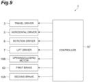
- the body unit 4 includes a traveling drive unit 3, a horizontal drive unit (body unit) 5, a rotary drive unit (body unit)6, a lifting drive unit (body unit) 7, and a controller 67.
- the elevator 10 includes a holding device (gripper) 11, a first suspension attaching portion (suspension attaching portion) 50 (refer to FIG.3 ), a second suspension attaching portion (suspension attaching portion) 40 (refer to FIG.5 ), a link mechanism 70 (refer to FIG.4 ), and a lock mechanism 60 (refer to FIG.5 ).
- the overhead transport vehicle 1 is provided with a pair of covers 8, 8 in the front-rear direction to cover the horizontal drive unit 5, the rotary drive unit 6, the lifting drive unit 7, the elevator 10, and the holding device 11.
- the pair of covers 8, 8 form a space to accommodate FOUP 90 below the holding device 11 when the elevator 10 has reached an upward end.
- a fall-preventing mechanism 8A prevents FOUP 90 held by the holding device 11 from dropping when the elevator 10 has reached the upward end.
- a swaying suppression mechanism 8B prevents FOUP 90 held by the holding device 11 from swinging in the front-rear direction (traveling direction) and left-right direction of the overhead transport vehicle 1 during travel.
- the traveling drive unit 3 that drives the overhead transport vehicle 1 to travel along the traveling rail 2 is arranged in the traveling rail 2.
- the traveling drive unit 3 drives a roller (not shown) traveling on the traveling rail 2.
- the horizontal drive unit 5 is provided below the traveling drive unit 3 via an axis 3A.
- the horizontal drive unit 5 drives the rotary drive unit 6, the lifting drive unit 7, and the elevator 10 to move within the horizontal plane in the direction (left-right direction) perpendicular to the extending direction of the traveling rail 2.
- the rotary drive unit 6 drives the lifting drive unit 7 and the elevator 10 to rotate within the horizontal plane.
- the lifting drive unit 7 drives the elevator 10 to ascend and descend by winding and paying out four belts (suspension member) 9.
- An appropriate means of suspension such as a wire or a rope may be used instead of the belts 9 attached to the lifting drive unit 7.
- the elevator 10 As shown in FIG.1 and FIG.2 , the elevator 10 according to the present preferred embodiment of the present invention is provided so as to be vertically movable by the lifting drive unit 7 and serves as an elevating platform in the overhead transport vehicle 1.
- the elevator 10 includes the holding device 11 that grips FOUP 90 and is lifted up by the belts 9 with respect to the horizontal drive unit 5, the rotary drive unit 6 and the lifting drive unit 7 included in the body unit.
- the holding device 11 holds FOUP 90.
- the holding device 11 includes a pair of L-shaped arms 12, 12, claws 13, 13 each fixed to arms 12, 12, and an opening/closing mechanism 15 to open/close the pair of arms 12, 12.
- the pair of arms 12, 12 are provided at the opening/closing mechanism 15.
- the opening/closing mechanism 15 moves the pair of arms 12, 12 in the direction close to each other or in the direction far from each other.
- the pair of arms 12, 12 are advanced/retreated in the front-rear direction by the operation of the opening/closing mechanism 15. Thereby, the pair of claws 13, 13 fixed to the arms 12, 12 open or close.
- the opening/closing mechanism 15 includes a second brake 15A (refer to FIG.9 ) and an opening/closing motor (driving unit) 15B (refer to FIG.9 ).
- the second brake 15A which is a non-excitation operative brake, locks opening/closing of the claws 13, 13 when no voltage is applied and releases the lock when a voltage is applied.
- the opening/closing motor 15B opens/closes the claws 13, 13.
- the height of the holding device 11 is adjusted so that the holding surfaces of the claws 13 are placed below the lower surface of the flange 98.
- the pair of the claws 13, 13 are closed in this state, so that the holding surfaces of the claws 13, 13 are extended below the lower surface of the flange 98.
- the elevator 10 is lifted up in this state, so that the flange 98 is gripped by the pair of the claws 13, 13 to support FOUP 90.
- the elevator 10 includes a base 10A on which the holding device 11 is provided, a cover 10B covering the base 10A, a first suspension attaching portion 50 that supports the base 10A to be vertically movable from below in a vertical direction via the vibration isolator 50A, and a second suspension attaching portion 40 that supports the base 10A to be vertically movable from below in a vertical direction via the vibration isolator 40A.
- FIG. 3 is a front view showing the outline of the first suspension attaching portion and FIG. 4 is a front view showing the outline of the second suspension attaching portion.
- FIG.3 does not show a part of a first body member 54 (to be described later) and a part of the link mechanism 70 connected to the first suspension attaching portion 50.
- the first suspension attaching portion 50 and the second suspension attaching portion 40 are mechanisms to couple the belts 9 with the elevator 10 (refer to FIG. 1 ) and to prevent vibration generated by traveling of the traveling drive unit 3 or by ascending/descending of the elevator 10 from being transmitted to FOUP 90.
- the first suspension attaching portion 50 is provided at the right side of the elevator 10 in the left-right direction. As shown in FIG. 3 , the first suspension attaching portion 50 is arranged at two places in the front-rear direction.
- the first suspension attaching portion 50 includes a connection member 51, a swing member 53, the first body member 54, a second body member 56, first axes 57, 57, a coupler 96, a clamper 95, and the vibration isolator 50A.
- the vibration isolator 50A includes a pair of first biasing portions 58, 58, a pair of second biasing portions 91A, 91A, and a pair of third biasing portions 92A, 92A.
- the connection member 51 is attached to the belt 9.
- the swing member 53 is coupled with the connection member 51.
- the swing member 53 is rotatably coupled with the connection member 51 via a first pin 52.
- the first body member 54 is formed in a substantially U-shape such that the top end thereof is open and the bottom thereof is flat in the horizontal direction.
- the upper ends of the first body member 54 are coupled with both ends of the swing member 53 with bolts 55.
- the first body member 54 includes a first supporter 54A (refer to FIG.5 and FIG.6 ) and a second supporter 54B (refer to FIG.5 and FIG.6 ).
- the first supporter 54A supports the first biasing portion 58 from below.
- the second supporter 54B is perpendicular to the first supporter 54A.
- a second body member 56 couples the center or the substantially center of the swing member 53 with the center or the substantially center of the first body member 54 in the front-rear direction.
- a pair of the first axes 57, 57 are in a bar-shape extending upwards from the first supporter 54A and arranged at both sides of the second body member 56 in the front-rear direction.
- An end of the first axis 57 at the side of the base 10A is inserted into an insertion hole formed on the base 10A and is fixed to the base 10A with the clamper 95 that clamps the base 10A.
- the pair of first biasing portions 58, 58 are compression coil springs having predetermined spring constants.
- the pair of first axes 57, 57 are inserted into the first biasing portions 58, 58, respectively.
- the top ends of the pair of first biasing portions 58, 58 are in contact with the base 10A and the bottom ends thereof are in contact with the first supporter 54A.
- the pair of the first biasing portions 58, 58 are provided so as to be in contact with both of the first supporter 54A and the base 10A and bias in the direction to keep the first supporter 54A and the base 10A away from each other.
- the first biasing portion 58 functions as a vibration isolator to reduce vibration transmitted to the members in contact with each other.
- the pair of second biasing portions 91A, 91A are made of urethane rubber and have viscoelasticity.
- the second biasing portions 91A, 91A are disposed such that the top ends thereof are away from the base 10A and the bottom ends thereof are in contact with the first supporter 54A. In other words, the pair of second biasing portions 91A, 91A are in contact only with the first supporter 54A. If a load more than a predetermined weight is applied to the first biasing portions 58, 58, the pair of second biasing portions 91A, 91A come in contact with both of the coupler 96 and the base 10A and bias in the direction to keep the coupler 96 and the base 10A away from each other.
- the pair of third biasing portions 92A, 92A are made of urethane rubber and have viscoelasticity.
- the pair of third biasing portions 92A, 92A are each disposed between the base 10A and the clamper 95.
- the pair of third biasing portions 92A, 92A are in contact with both of the base 10A and the clamper 95, and bias in the direction to keep the base 10A and the clamper 95 away from each other.
- the second suspension attaching portion 40 is provided at the left side of the elevator 10 in the left-right direction. As shown in FIG.4 , the second suspension attaching portion 40 is provided in the vicinity of the center in the front-rear direction.
- the second suspension attaching portion 40 includes connection members 41, 41, a swing member 43, a third body member 45, a fourth body member 46, second axes 47, 47, a clamper 94, and the vibration isolator 40A.
- the vibration isolator 40A includes a pair of first biasing portions 48, 48, a pair of second biasing portions 91B, 91B, and a pair of third biasing portions 92B, 92B.
- connection members 41, 41 are members to which the belts 9, 9 are attached.
- the swing member 43 couples the pair of connection members 41, 41 with the third body unit 45.
- the pair of connection members 41, 41 are rotatably coupled with the swing member 43 in both directions via a pair of third pins 42, 42.
- the swing member 43 is rotatably coupled with the third body member 45 in both directions via a fourth pin 44.
- the fourth body member 46 which is coupled with the bottom end of the third body member 45, extends in the horizontal direction.
- the fourth body member 46 includes a third supporter 46A and a fourth supporter 46B.
- the third body member 45 supports the first biasing portions 48, 48 from below.
- the third supporter 46A supports the second biasing portions 91B, 91B from below.
- the fourth supporter 46B is perpendicular to the third supporter 46A.
- the pair of second axes 47, 47 which extend upwards from the bottom end of the third body member 45, are arranged at both sides of the third body member 45 in the front-rear direction. An end of the second axis 47 at the side of the base 10A is inserted into the insertion hole formed on the base 10A and is fixed to the base 10A with the clamper 94 that clamps the base 10A.
- the pair of first biasing portions 48, 48 are compression coil springs having a predetermined spring constants.
- the pair of second axes 47, 47 are inserted into the first biasing portions 48, 48, respectively.
- the top ends of the pair of first biasing portions 48, 48 are in contact with the base 10A and the bottom ends thereof are in contact with the third body member 45.
- the pair of the first biasing portions 48, 48 are provided in contact with both of the third body member 45 and the base 10A and bias in the direction to keep the third body member 45 and the base 10A away from each other.
- the first biasing portion 48 functions as a vibration isolator to reduce vibration transmitted to the members in contact with each other.
- the pair of second biasing portions 91B, 91B are made of urethane rubber and have viscoelasticity.
- the second biasing portions 91B, 91B are disposed such that the top ends thereof are away from the base 10A and the bottom ends thereof are in contact with the third supporter 46A. In other words, the pair of second biasing portions 91B, 91B are in contact only with the third supporter 46A. If a load more than a predetermined weight is applied to the first biasing portions 48, 48, the pair of second biasing portions 91B, 91B come in contact with both of the third supporter 46A and the base 10A and bias in the direction to keep the third supporter 46A and the base 10A away from each other.
- the pair of third biasing portions 92B, 92B are made of urethane rubber and have viscoelasticity.
- the pair of third biasing portions 92B, 92B are each disposed between the base 10A and the clamper 94.
- the pair of third biasing portions 92B, 92B are in contact with both of the base 10A and the clamper 94, and bias in the direction to keep the base 10A and the clamper 94 away from each other.
- the link mechanism 70 couples two of the first suspension attaching portions 50 and the second suspension attaching portion 40 that are arranged in the left-right direction (width direction) perpendicular to both of the front-rear direction (traveling direction) and the vertical direction (perpendicular direction) with each other and further couples two of the first suspension attaching portions 50, 50 arranged in the front-rear direction with each other.
- the link mechanism 70 operates to ensure similarity of respective distances between the first body member 54 (coupler 96) in the first suspension attaching portion 50 and base 10A and between the fourth body member 46 in the second suspension attaching portion 40 and the base 10A.
- the link mechanism 70 operates to ensure similarity of respective distances between the first body member 54 in the first suspension attaching portion 50 arranged at left side and the base 10A and between the first body member 54 in the first suspension attaching portion 50 arranged at right side and the base 10A.
- the link mechanism 70 will be described in detail.
- the link mechanism 70 includes a first shaft 71, a second shaft 72, a third shaft 73, a fourth shaft 74, a first bush 81, a first block 82, a second block 83, a second bush 84, a third bush 85, a fixing portion 86, and a coupling portion 88.
- the first shaft 71 is supported by the first bush 81 fixed to the fourth supporter 46B included in the second suspension attaching portion 40 and extends in the front-rear direction.
- the first shaft 71 is inserted into an insertion hole 81A formed on the first bush 81 and provided so as to be capable of rotating with respect to the first bush 81 and sliding in the axis direction.
- a material for the first bush 81 is appropriately selected so that the first shaft 71 has a predetermined rotation capacity and a predetermined sliding property.
- Two of the first shafts 71 arranged in the front-rear direction are disposed in a substantially straight line in the front-rear direction.
- the first shafts 71 are on a straight line with the second axes 47, 47 (refer to FIG. 4 ) that are inserted into the pair of first biasing portions 48, 48, respectively.
- the third shaft 73 is supported by the second bush 84 fixed to the second supporter 54B included in the first suspension attaching portion 50 and extends in the front-rear direction.
- the third shaft 73 is inserted into an insertion hole 84A formed on the second bush 84 and provided so as to be capable of rotating with respect to the second bush 84 and sliding in the axis direction.
- the fourth shaft 74 is supported by the third bush 85 fixed to the second supporter 54B included in the first suspension attaching portion 50 and extends in the front-rear direction.
- the fourth shaft 74 is inserted into an insertion hole 85A formed on the third bush 85 and provided so as to be capable of rotating with respect to the third bush 85 and sliding in the axis direction.
- materials for the second bush 84 and the third bush 85 are appropriately selected so that the third shaft 73 and the fourth shaft 74 have a predetermined rotation capacity and a predetermined sliding property.
- the third shaft 73 and the fourth shaft 74 are arranged at both sides of the first suspension attaching portion 50 in parallel to each other. Two of the third shafts 73, 73 arranged in the front-rear direction are disposed in a straight line in the front-rear direction and coupled with each other via the coupling portion 88 (to be described later). Two of the fourth shafts 74, 74 arranged in the front-rear direction are disposed in a straight line in the front-rear direction.
- the second shaft 72 which is supported by the first block 82 (or a gear 61D which is a part of the lock mechanism 60 to be described later) and the second block 83 fixed to bottom surface of the base 10A, extends in the left-right direction.
- the second shaft 72 is inserted into an insertion hole 83A formed on the second block 83 and provided so as to be capable of rotating with respect to the second block 83 and sliding in the axis direction.
- One end of the second shaft 72 in the left-right direction is coupled with the first shaft 71.
- an end of the first shaft 71 is inserted into an insertion hole 72A formed on the second shaft 72.
- the other end of the second shaft 72 in the left-right direction is coupled with the third shaft 73.
- an end of the third shaft 73 is inserted into an insertion hole 72B formed on the second shaft 72.
- the second shaft 72 is coupled with the fourth shaft 74 between the first block 82 (or the gear 61D) and the second block 83 in the left-right direction.
- the second shaft 72 is coupled with the fourth shaft 74 via the fixing portion 86 fixed to the bottom surface of the base 10A.
- the fixing portion 86 absorbs the fit tolerance of the fourth shaft 74 and the second shaft 72.
- the third shaft 73 coupled with the first suspension attaching portion 50 disposed at the front side and the third shaft 73 coupled with the first suspension attaching portion 50 disposed at the rear side are coupled with each other via the coupling portion 88.
- the coupling portion 88 is located in the substantially central position of the two second bushes 84, 84 arranged in the front-rear direction.
- the coupling portion 88 includes an inserted portion 88A having the inner diameter larger than the outer diameter of the third shaft 73 arranged in the front side.
- the third shaft 73 is fixed, for example, at a place within the inserted portion 88A via a supporter such as a resin. Thereby, the third shaft 73 is capable of moving within the inserted portion 88A in the vertical and horizontal direction.
- the lock mechanism 60 fixes a relative positional relation (a relative position of the base 10A with respect to the first body member 54 and a relative position of the first body member 54 with respect to the base 10A) between the body member 54 (the coupler 96) included in the first suspension attaching portion 50 and the base 10A.
- the lock mechanism further fixes a relative positional relation (a relative position of the base 10A with respect to the fourth body member 46 and a relative position of the fourth body member 46 with respect to the base 10A) between the fourth body member 46 included in the second suspension attaching portion 40 and the base 10A.
- the lock mechanism 60 is provided at the base 10A and includes a gear mechanism (interlocker) 61 and a first brake (switch) 62.
- the gear mechanism 61 includes a bearing 61A, an axis 61B, a gear receiver 61C, and the gear 61D.
- the bearing 61A is fixed to the base 10A.
- the axis 61B is rotatably provided at the bearing 61A.
- the gear receiver 61C which is in a cylindrical shape, is attached to the axis 61B.
- the gear receiver 61C is provided so as to be capable of rotating along with rotation of the axis 61B.
- One end of the gear 61D is fixed to the second shaft 72.
- the other end of the gear 61D is arranged so as to be in contact with the outer periphery of the gear receiver 61C.
- the gear receiver 61C When the gear receiver 61C is in a rotatable state (in an unlocked state (to be described later)) and one end of the gear 61D rotationally moves along with the movement of the second shaft 72, the other end of the gear 61D works together with the gear receiver 61C and oscillates in contact with the outer periphery of the gear receiver 61C (refer to FIGS. 8(A) and 8 (B) ).
- the gear 61D is capable of moving according to the distance between the first body member 54 (coupler 96) included in the suspension attaching portion 50 and the base 10A and the distance between the fourth body member 46 included in the suspension attaching portion 40 and the base 10A.
- the first brake 62 switches the gear receiver 61C included in the gear mechanism 61 between a movable and an immovable state.
- the first brake 62 switches the axis 61B rotatably provided at the axis receiver 61A between a rotatable and a nonrotatable state.
- the first brake 62 which is an excitation operative brake, causes the axis 61B to be in a nonrotatable state when the voltage is applied and to be in a rotatable state when no voltage is applied.
- the first brake 62 causes the lock mechanism 60 to be in the locked state by making the gear receiver 61C nonmovable and to be in the unlocked state by making the gear receiver 61C movable.
- the controller 67 is an electronic control unit made up of a CPU (Central Processing Unit), ROM (Read Only Memory), RAM (Random Access Memory), and the like.
- the controller 67 controls a variety of operations in the overhead transport vehicle 1.
- the controller 67 controls the traveling drive unit 3, the horizontal drive unit 5, the rotary drive unit 6, the lifting drive unit 7, the first brake 62, the second brake 15A, and the opening/closing motor 15B.
- the controller 67 may be configured, for example, as software in which a program stored in ROM is loaded on RAM and executed by the CPU.
- the controller 67 may also be configured as hardware which is an electronic circuit or the like.
- the controller 67 communicates with the upper controller (not shown) using the power supply unit (power supply line of the traveling rail 2 or feeder wire).
- the controller 67 makes the lock mechanism 60 enter the locked state at least partially during an elevating operation of the elevator 10 and release the locked state at least partially during a traveling operation of the body unit 4 to make the lock mechanism 60 enter the unlocked state.
- the controller 67 further controls the first brake 62 so that the lock mechanism is in the locked state while the elevating operation of elevator 10 is inactive.
- the controller 67 controls the lock mechanism 60 to operate so as to be in the locked state based on a winding amount of the belt 9.
- FOUP 90 is lifted up by the elevator 10, so that the first biasing portion 58 included in the first suspension attaching portion 50 is temporarily compressed and then expands again. After repeating this operation, the first biasing portion 58 enters a counterpoised state.
- the first biasing portion 48 of the second suspension attaching portion 40 is temporarily compressed and expands again. After repeating this operation, the first biasing portion 48 enters a counterpoised state.
- the above 'a predetermined distance' which is a distance at the timing of the above counterpoised state, is appropriately determined based on the weight of FOUP 90, the weight of the articles to be accommodated in FOUP 90, and the rising speed of the elevator 10.
- the controller 67 controls the first brake 62 to operate so that the lock mechanism 60 is in the locked state before the elevator 10 starts to descend.
- the pressurization is previously applied to the first biasing portion 58 which is a compression spring.
- the first biasing portion 58 is compressed so as to obtain the same repulsion as the total weight of the base 10A, the holding device 11, and the empty FOUP 90.
- the holding device 11 grips FOUP 90 accommodating any articles, and a load larger than the first predetermined weight acts on the first biasing portion 58, so that the first biasing portion 58 is compressed.
- the base 10A does not come into contact with an end of the second biasing portion 91A. Therefore, the base 10A is supported by the first body member 54 (coupler 96) only via the first biasing portion 58.
- the first biasing portion 58 If a load of a second predetermined weight even larger than the first predetermined weight acts on the first biasing portion 58, the first biasing portion 58 is further compressed and the base 10A comes into contact with the end of the second biasing portion 91A. Therefore, the base 10A is supported by the first body member 54 (coupler 96) via the first biasing portion 58 and the second biasing portion 91A.
- the amount of sinking with respect to the same weight is smaller. Therefore, the coefficient of restitution of the vibration isolator 50A is changed when the load of the second predetermined weight acts on the first biasing portion 58.
- the first biasing portion 58 contracts and the second biasing portion 91A comes into contact with the base 10A, so that a repulsion occurs in the second biasing portion 91A. Vibration is generated to the base 10A by the repulsion.
- the third biasing portion 92A disposed between the base 10A and the clamper 95 absorbs the upward shock generated by the repulsion.
- a pressurization is previously applied to the first biasing portion 48 which is a compression spring in order to prevent the first biasing portion 48 from being compressed when the holding device 11 grips an empty FOUP 90.
- the first biasing portion 48 is compressed so as to obtain the same repulsion as the total weight of the base 10A, the holding device 11, and the empty FOUP 90.
- the holding device 11 grips FOUP 90 accommodating any articles, and a load larger than the first predetermined weight acts on the first biasing portion 48, so that the first biasing portion 48 is compressed.
- the base 10A does not come into contact with an end of the second biasing portion 91B. Therefore, the base 10A is supported by the fourth body member 46 only via the first biasing portion 48.
- the load of the second predetermined weight even larger the first predetermined weight acts on the first biasing portion 48, so that the first biasing portion 48 is further compressed and the base 10A comes into contact with an end of the second biasing portion 91B. Therefore, the base 10A is supported by the fourth body member 46 via the first biasing portion 48 and the second biasing portion 91B. Compared to being supported by the fourth body member 46 only via the first biasing portion 48, when the base 10A is supported by the body member 46 via the first biasing portion 48 and the second biasing portion 91B, the amount of sinking with respect to the same weight (amount of approaching between the base 10A and the fourth body member 46) is smaller. Therefore, the coefficient of restitution of the vibration isolator 40A is changed when the load of the second predetermined weight acts on the first biasing portion 48.
- the first biasing portion 48 contracts and the second biasing portion 91B comes into contact with the base 10A, so that repulsion occurs in the second biasing portion 91B. Vibration is generated to the base 10A by the repulsion.
- the third biasing portion 92B disposed between the base 10A and the clamper 94 absorbs the upward shock generated by the repulsion.
- a force acts on the first biasing portions 48, 48 of the second suspension attaching portion 40 arranged at left side by the centrifugal force generated during travel.
- the force acts on the first biasing portions 48, 48 of the second suspension attaching portion 40, so that the first biasing portions 48, 48 are compressed and the fourth body member 46 moves upward (in the direction of arrow D1).
- the distance between the fourth body member 46 and the base 10A is reduced.
- the fourth body member 46 moves upward, so that one end of the first shaft 71 (at the side of the first bush 81) fixed to the fourth body member 46 via the first bush 81 moves upward (in the direction of arrow D2) based on the other end being coupled with the second shaft 72.
- the end of the first shaft 71 at the side of the first bush 81 moves upward, so that the second shaft 72 rotates clockwise (in the direction of arrow D3).
- the second shaft 72 rotates clockwise, so that one end of the third shaft 73 (at the side of the coupling portion 88) coupled with the second shaft 72 moves upward (in the direction of arrow D4) based on the other end being coupled with the second shaft 72.
- the second shaft 72 rotates clockwise, so that one end of the fourth shaft 74 at the side opposite to the side being coupled with the second shaft 72 moves upward (in the direction of arrow D4) based on the other end of the fourth shaft 74 at the side being coupled with the second shaft 72.
- the first body member 54 fixed to the third shaft 73 via the second bush 84 and fixed to the fourth shaft 74 via the third bush 85 is pushed upward (in the direction of arrow D5).
- the first body member 54 is pushed upward, so that a pair of the first biasing portions 58, 58 are compressed.
- the distance between the first body member 54 and the base 10A is reduced.
- first biasing portions 48, 48 expand and the fourth body member 46 moves downward (in the opposite direction of arrow D1), so that one end of the first shaft 71 (at the side of the first bush 81) moves downward (in the opposite direction of arrow D2) based on the other end being coupled with the second shaft 72.
- the end of the first shaft 71 at the side of the first bush 81 moves downward, so that the second shaft 72 rotates counterclockwise (in the opposite direction of arrow D3) .
- the second shaft 72 rotates counterclockwise, so that one end of the third shaft 73 at the side of the coupling portion 88 moves downward (in the opposite direction of arrow D4) based on the other end being coupled with the second shaft 72 and one end of the fourth shaft 74 at the side opposite to the side being coupled with the second shaft 72 moves downward (in the opposite direction of arrow D4) based on the other end at the side being coupled with the second shaft 72.
- the first body member 54 is pushed downward (in the opposite side of arrow D5) and the pair of the first biasing portions 58,58 expand.
- the link mechanism 70 coupling between the second suspension attaching portion 40 and the first suspension attaching portion 50 that are arranged in the left-right direction, when a spring member of one of the second suspension attaching portion 40 and the first suspension attaching portion 50 contracts or expands, the second shaft 72, following the movement, rotates based on the first block 82 (or gear 61D) and the second block 83 fixed to bottom surface of the base 10A, so that a spring member of the other of the second suspension attaching portion 40 and the first suspension attaching portion 50 expands or contracts.
- the link mechanism 70 operates so as to ensure similarity of respective distances between the base 10A and the fourth body member 46 and between the base 10A and the first body member 54 in the second suspension attaching portion 40 and the first suspension attaching portion 50 coupled with each other.
- the link mechanism 70 includes the second shaft 72 in which a stress (torsional stress) occurs when there is a difference in the distance between the base 10A and the fourth body member 46 and the distance between the base 10A and the first body member 54 in the second suspension attaching portion 40 and the first suspension attaching portion 50 coupled with each other.
- the reaction force against the stress that occurs in the second shaft 72 serves as a force to ensure similarity of respective distances between the base 10A and the fourth body member 46 and between the base 10A and the first body member 54 in the second suspension attaching portion 40 and the first suspension attaching portion 50 coupled with each other.
- the first body member 54 moves upward (in the direction of arrow D5), so that one end (at the side of the coupling portion 88) of the third shaft 73 fixed to the first body member 54 via the second bush 86 moves upward (in the direction of arrow D6) based on the other end at the side being coupled with the second shaft 72.
- the coupling portion 88 moves upward (in the direction of arrow D6), so that one end (at the side of the coupling portion 88) of the other third shaft 73 coupled with the coupling portion 88 (the third shaft 73 arranged at the left side in FIG. 5 ) also moves upward (in the direction of arrow D6) based on the other end of the third shaft 73 at the side being coupled with the second shaft 72.
- the first body member 54 in the first suspension attaching portion 50 arranged at the front side and fixed to the third shaft 73 via the second bush 84 is pushed upward (in the direction of arrow D7).
- the first body member 54 is pushed upward, so that the pair of the first biasing portions 58, 58 are compressed.
- the distance between the first body member 54 and the base 10A is reduced.
- the first biasing portions 58, 58 in the first suspension attaching portion 50 arranged at the front side expand and the first body member 54 moves downward (in the opposite direction of arrow D5), so that one end of the third shaft 73 at the side of the coupling portion 88 moves downward (in the opposite direction of arrow D6) based on the other end being coupled with the second shaft 72.
- the coupling portion 88 moves downward, so that one end (at the side of the coupling portion 88) of the other third shaft 73 being coupled with the coupling portion 88 also moves downward (in the opposite direction of arrow D6) based on the other end being coupled with the second shaft 72.
- the first body member 54 in the first suspension attaching portion 50 arranged at the front side is pushed downward (in the opposite side of arrow D7).
- the first body member 54 is pushed downward, so that the pair or the first biasing portions 58, 58 expand.
- the link mechanism 70 that couples between the first suspension attaching portions 50 arranged in the front-rear direction as the above, the first biasing portions 58, 58 in one first suspension attaching portion 50 compress or expand, so that the movement of one third shaft 73 is followed by the movement the other third shaft 73 based on the coupling portion 88 to shrink or expand the first biasing portions 58, 58 in the other first suspension attaching portion 50. Therefore, the link mechanism 70 operates to ensure similarity of respective distances between the base 10A and the respective first body members 54, 54 in the first suspension attaching portions 50 coupled with each other.
- the link mechanism 70 includes the third shaft 73 in which a stress (torsional stress) occurs when there is a difference in the respective distances between the base 10A and the respective first body members 54 in the first suspension attaching portions 50 coupled with each other.
- the reaction force against the stress that occurs in the third shaft 73 functions as a force to ensure similarity of respective distances between the base 10A and the first body members 54 in the first suspension attaching portions 50 coupled with each other.
- the restriction of movement of the link mechanism 70 leads to the restriction of movements of the first biasing portion 58 in the first suspension attaching portion 50 and the first biasing portion 48 in the second suspension attaching portion 40. Therefore, the locked state is established in which a relative positional relation between the first body member 54 (coupler 96) in the first suspension attaching portion 50 and the base 10A is fixed, and a relative positional relation between the fourth body member 46 (coupler 96) in the second suspension attaching portion 40 and the base 10A is fixed.
- the controller 67 of the overhead transport vehicle 1 causes the opening/closing motor 15B to operate so as to close the claws 13, 13 (step S3), in order to grip FOUP 90.
- the controller 67 causes the elevator 10 to ascend at the predetermined distance (creep-up) and stop ascending temporarily in order to check the gripping condition of FOUP 90 (step S4).
- the controller 67 causes the elevator 10 to restart ascending and stopping at the prescribed position (original position) of the elevator 10 during travel (step 6).
- These stopping operations of the elevator 10 at step S4 and step S6 may be controlled based on a signal sent from the controller 67 or based on whether the predetermined amount of the belt 90 is paid out or not.
- the elevator 10 is placed (stored) in its original position and then the overhead transport vehicle 1 starts to travel (step 7) and stops at the target position (destination) (step 8).
- the controller 67 performs control so that the voltage is not be applied to the first brake 62 in order to make the lock mechanism 60 enter the unlocked state until the elevator 10 descends and creeps up (steps S1 to S4).
- the lock mechanism 60 may enter the locked state, however, there are further benefits in terms of power consumption in the unlocked state during which the voltage is not applied.
- the controller 67 performs control so that the voltage is applied to the first brake 62 and the lock mechanism 60 enter the locked state.
- the controller 67 causes the lock mechanism 60 to be in the locked state.
- the controller 67 controls the lock mechanism 60 to be in the locked state before the elevator 10 starts to ascend/descend, i.e., in the state in which the ascending/descending movement of the elevator 10 is inactive.
- the controller 67 stops the voltage application to the first brake 62 and causes the lock mechanism 60 to be in the unlocked state.
- the controller 67 controls so that the voltage is applied to the second brake 15A and the holding device 11 enter an unlocked state, and also controls the opening/closing motor 15B.
- the controller 67 performs control so that the holding device 11 enters the locked state without applying the voltage to the second brake 15A.
- unloading FOUP 90 unloading control
- the unloading operations performed at steps S1 to S9 are different from the above gripping operations in that FOUP 90 is gripped at step S1, that the elevator 10 stops when the predetermined amount of paying-out is detected at step S2, that the claws are open at step S3, and that FOUP 90 is not gripped at steps S4 to S8.
- the controller 67 performs control so that the voltage is applied to the first brake 62 in order to make the lock mechanism 60 enter the locked state until the elevator 10 descends to the transfer place (steps S1 to S2).
- the controller 67 controls the lock mechanism 60 to enter the locked state before the elevator 10 starts to descend.
- FOUP 90 is loaded on the transfer place (steps S3 to S8)
- the controller 67 performs control so that the lock mechanism 60 enters the unlocked state without applying the voltage to the first brake 62.
- the controller 67 performs control so that the voltage is applied to the second brake 15A and the holding device 11 enters the unlocked state and also controls the opening/closing motor 15B.
- the controller 67 performs control so that the holding device 11 is in the locked state without applying the voltage to the second brake 15A.
- the vibration isolator 50A and the vibration isolator 40 are provided between the first suspension attaching portion 50 and the base 10A and between the second suspension attaching portion 40 and the base 10A, respectively.
- vibration generated during travel is absorbed by the vibration isolator 50A and the vibration isolator 40A, and is not easily transmitted to FOUP 90.
- the lock mechanism 60 assumes the locked state at least partially during elevating operation of the elevator 10, so that vibration generated by the vibration isolator 50A and the vibration isolator 40A is reduced, allowing for an easy positioning of FOUP 90 to be transferred.
- FOUP 90 to be transferred is easily positioned and vibration transmitted to FOUP 90 during travel is reduced.
- the lock mechanism 60 includes the gear 61D, which is provided at the base 10A and is capable of moving according to the distance between the suspension attaching portion 50 and the base 10A and the distance between the suspension attaching portion 40 and the base 10A, and the first brake 62 that switches the gear 61D between a movable state and an immovable state.
- the first brake 62 causes the gear mechanism 61 to be in an immovable state, which causes the lock mechanism 60 to be in the locked state and the gear mechanism 61 to be in a movable state, which causes the lock mechanism 60 to be in the unlocked state.
- the lock mechanism 60 can be configured simply.
- the configuration of the lock mechanism 60 allows the switching operation between locked and unlocked to be easier than a configuration (compared configuration) that establishes the locked state, for example, by bringing a part of a supporter (a member corresponding to the fourth body member 46 or the coupler 96) into contact with a part of the base 10A and that establishes the unlocked state by causing a part provided at a supporter to break contact with a part of the base 10A.
- a braking mechanism is employed as the first brake 62 that establishes an immovable state when voltage is applied and a movable state when no voltage is applied.
- Another braking mechanism is further employed as the second brake 15A that locks an opening/closing of the claws 13, 13 when no voltage is applied and that releases the locked claws 13, 13 when voltage is applied.
- the link mechanism 70 is provided so as to ensure similarity of respective distances between the base 10A and the first suspension attaching portion 50 and between the base 10A and the second suspension attaching portion 40 coupled with the first suspension attaching portion 50. This can suppress a rolling operation of the elevator 10 during travel.
- the link mechanism 70 couples between the first suspension attaching portion 50 and the second suspension attaching portion 40 that are arranged in the left-right direction (width direction) perpendicular to both of the front-rear direction and up-down direction in which the traveling drive unit 3 travels, so that a roll motion in the width direction caused by curve-traveling or transferring FOUP 90 in the lateral direction can be suppressed.
- the link mechanism 70 couples between two of the first suspension attaching portions 50 arranged in the direction in which the traveling drive unit 3 travels, so that a roll motion in the front-rear direction caused by acceleration or deceleration during travel can be suppressed.
- the controller 67 controls so that the lock mechanism 60 is locked while the elevating operation of the elevator 10 is inactive. Therefore, vibrations caused by a locking operation performed by the lock mechanism 60 can be reduced.
- the controller 67 controls so that the lock mechanism is in the locked state after FOUP 90 is lifted from the transfer place a predetermined distance (step S4).
- a behavior temporary compression and expansion
- the first biasing portions 48, 58 to absorb vibration generated when FOUP 90 is lifted from the transfer place.
- the behavior is restarted after the lock is released.
- This configuration enables a state in which the behavior of the first biasing portions 48, 58 converges, that is, a state in which the lock mechanism 60 is locked when the first biasing portions 48, 58 are counterpoised. Therefore, FOUP 90 does not move up/down when the lock mechanism is unlocked. This can reduce vibration generated by unlocking.
- the controller 67 controls the first brake 62 so that the lock mechanism 60 is locked before the elevator 10 starts to descend. Thereby, vibration generated by the elevating operation of the elevator 10 can be reduced more surely.
- the link mechanism 70 couples between two of the first suspension attaching portions 50 and the second suspension attaching portion 40 arranged in the left-right direction and also couples between the first suspension attaching portions 50 arranged in the front-rear direction.
- the link mechanism 70 may not be provided in the overhead transport vehicle 1.
- the above lock mechanism 60 corresponding to each of the first suspension attaching portions 50 and the second suspension attaching portion 40 may be provided to cause an end of the gear 61D to come into contact with each of the fourth body member 46 and the coupler 96.
- the lock mechanism 60 is locked, so that the distance between the first body member 54 (coupler 96) in the first suspension attaching portion 50 and the base 10A and the distance between the fourth body member 46 in the second suspension attaching portion 40 and the base 10A can be fixed.
- the first suspension attaching portion 50 is provided at the right side of the elevator 10 in the left-right direction and the second suspension attaching portion 40 is provided at the left side of the elevator 10 in the left-right direction, but is not limited to this configuration.
- the positions of the first suspension attaching portion 50 and the second suspension attaching portion 40 in the left-right direction may be switched.
- the first suspension attaching portions 50 or the second suspension attaching portions 40 may be provided at the both sides in the left-right direction.
- a gel-like elastic body made of a silicone resin may be provided instead of or in addition to the first biasing portion 58 or the first biasing portion 48 according to the above preferred embodiment and the variant.
- vibration or shock can be absorbed.
- the controller 67 that controls the rock mechanism 60 is provided at the body unit 4.
- another controller may be provided at the elevator 10.
- the stopping of the elevator 10 at the original position is controlled by the signal sent from the controller 67, but may also be controlled by a sensor provided at the elevator 10 to detect the original position.
Landscapes
- Engineering & Computer Science (AREA)
- Mechanical Engineering (AREA)
- Physics & Mathematics (AREA)
- Condensed Matter Physics & Semiconductors (AREA)
- General Physics & Mathematics (AREA)
- Manufacturing & Machinery (AREA)
- Computer Hardware Design (AREA)
- Microelectronics & Electronic Packaging (AREA)
- Power Engineering (AREA)
- Carriers, Traveling Bodies, And Overhead Traveling Cranes (AREA)
- Container, Conveyance, Adherence, Positioning, Of Wafer (AREA)
- Vibration Prevention Devices (AREA)
Applications Claiming Priority (2)
| Application Number | Priority Date | Filing Date | Title |
|---|---|---|---|
| JP2019167665 | 2019-09-13 | ||
| PCT/JP2020/029593 WO2021049203A1 (ja) | 2019-09-13 | 2020-07-31 | 天井搬送車 |
Publications (3)
| Publication Number | Publication Date |
|---|---|
| EP4029809A1 EP4029809A1 (en) | 2022-07-20 |
| EP4029809A4 EP4029809A4 (en) | 2023-10-11 |
| EP4029809B1 true EP4029809B1 (en) | 2024-06-12 |
Family
ID=74867343
Family Applications (1)
| Application Number | Title | Priority Date | Filing Date |
|---|---|---|---|
| EP20862790.1A Active EP4029809B1 (en) | 2019-09-13 | 2020-07-31 | Ceiling transport vehicle |
Country Status (7)
| Country | Link |
|---|---|
| US (1) | US20220402694A1 (zh) |
| EP (1) | EP4029809B1 (zh) |
| JP (1) | JP7276474B2 (zh) |
| CN (1) | CN114364620B (zh) |
| IL (1) | IL291102A (zh) |
| TW (1) | TWI830945B (zh) |
| WO (1) | WO2021049203A1 (zh) |
Family Cites Families (11)
| Publication number | Priority date | Publication date | Assignee | Title |
|---|---|---|---|---|
| JPS6019689A (ja) * | 1983-07-12 | 1985-01-31 | 株式会社片岡機械製作所 | 搬出装置 |
| JPH0637264U (ja) * | 1992-10-23 | 1994-05-17 | 村田機械株式会社 | 天井走行車 |
| JP2000012644A (ja) * | 1998-06-25 | 2000-01-14 | Kokusai Electric Co Ltd | カセット移載システム |
| JP2005194009A (ja) * | 2004-01-05 | 2005-07-21 | Asyst Shinko Inc | 懸垂型搬送台車 |
| JP4378656B2 (ja) * | 2007-03-07 | 2009-12-09 | 株式会社ダイフク | 物品搬送設備 |
| JP5445015B2 (ja) * | 2009-10-14 | 2014-03-19 | シンフォニアテクノロジー株式会社 | キャリア移載促進装置 |
| JP5668340B2 (ja) * | 2010-07-02 | 2015-02-12 | 村田機械株式会社 | 天井搬送車 |
| JP5648865B2 (ja) * | 2012-06-18 | 2015-01-07 | 株式会社ダイフク | 天井搬送車及び物品搬送設備 |
| JP6364371B2 (ja) | 2015-03-24 | 2018-07-25 | トヨタホーム株式会社 | 入退場管理システム |
| JP6344410B2 (ja) * | 2016-02-19 | 2018-06-20 | 村田機械株式会社 | 天井搬送車 |
| US10822205B2 (en) * | 2016-10-25 | 2020-11-03 | Murata Machinery, Ltd. | Overhead transport vehicle |
-
2020
- 2020-07-31 CN CN202080062151.3A patent/CN114364620B/zh active Active
- 2020-07-31 EP EP20862790.1A patent/EP4029809B1/en active Active
- 2020-07-31 JP JP2021545161A patent/JP7276474B2/ja active Active
- 2020-07-31 WO PCT/JP2020/029593 patent/WO2021049203A1/ja unknown
- 2020-07-31 US US17/641,466 patent/US20220402694A1/en active Pending
- 2020-09-11 TW TW109131213A patent/TWI830945B/zh active
-
2022
- 2022-03-03 IL IL291102A patent/IL291102A/en unknown
Also Published As
| Publication number | Publication date |
|---|---|
| JPWO2021049203A1 (zh) | 2021-03-18 |
| EP4029809A4 (en) | 2023-10-11 |
| IL291102A (en) | 2022-05-01 |
| TWI830945B (zh) | 2024-02-01 |
| WO2021049203A1 (ja) | 2021-03-18 |
| TW202116643A (zh) | 2021-05-01 |
| JP7276474B2 (ja) | 2023-05-18 |
| CN114364620A (zh) | 2022-04-15 |
| US20220402694A1 (en) | 2022-12-22 |
| CN114364620B (zh) | 2023-06-16 |
| EP4029809A1 (en) | 2022-07-20 |
Similar Documents
| Publication | Publication Date | Title |
|---|---|---|
| KR102165435B1 (ko) | 천장 반송차 | |
| TWI688538B (zh) | 高架搬運車 | |
| EP3932830B1 (en) | Ceiling transport vehicle | |
| EP4029809B1 (en) | Ceiling transport vehicle | |
| WO2024190220A1 (ja) | 天井搬送車 | |
| US20240002148A1 (en) | Overhead transport vehicle | |
| JP7537620B2 (ja) | 天井搬送車 | |
| WO2023013173A1 (ja) | 天井搬送車 | |
| WO2024176522A1 (ja) | 搬送装置 | |
| KR20220071902A (ko) | 반송차 | |
| TW202306865A (zh) | 高架搬運車 |
Legal Events
| Date | Code | Title | Description |
|---|---|---|---|
| STAA | Information on the status of an ep patent application or granted ep patent |
Free format text: STATUS: THE INTERNATIONAL PUBLICATION HAS BEEN MADE |
|
| PUAI | Public reference made under article 153(3) epc to a published international application that has entered the european phase |
Free format text: ORIGINAL CODE: 0009012 |
|
| STAA | Information on the status of an ep patent application or granted ep patent |
Free format text: STATUS: REQUEST FOR EXAMINATION WAS MADE |
|
| 17P | Request for examination filed |
Effective date: 20220308 |
|
| AK | Designated contracting states |
Kind code of ref document: A1 Designated state(s): AL AT BE BG CH CY CZ DE DK EE ES FI FR GB GR HR HU IE IS IT LI LT LU LV MC MK MT NL NO PL PT RO RS SE SI SK SM TR |
|
| DAV | Request for validation of the european patent (deleted) | ||
| DAX | Request for extension of the european patent (deleted) | ||
| A4 | Supplementary search report drawn up and despatched |
Effective date: 20230913 |
|
| RIC1 | Information provided on ipc code assigned before grant |
Ipc: B66C 13/04 20060101ALI20230907BHEP Ipc: H01L 21/677 20060101ALI20230907BHEP Ipc: B66C 11/04 20060101ALI20230907BHEP Ipc: B66C 13/06 20060101ALI20230907BHEP Ipc: B65G 1/04 20060101AFI20230907BHEP |
|
| GRAP | Despatch of communication of intention to grant a patent |
Free format text: ORIGINAL CODE: EPIDOSNIGR1 |
|
| STAA | Information on the status of an ep patent application or granted ep patent |
Free format text: STATUS: GRANT OF PATENT IS INTENDED |
|
| RIC1 | Information provided on ipc code assigned before grant |
Ipc: B66C 13/04 20060101ALI20231206BHEP Ipc: H01L 21/677 20060101ALI20231206BHEP Ipc: B66C 11/04 20060101ALI20231206BHEP Ipc: B66C 13/06 20060101ALI20231206BHEP Ipc: B65G 1/04 20060101AFI20231206BHEP |
|
| INTG | Intention to grant announced |
Effective date: 20240103 |
|
| GRAS | Grant fee paid |
Free format text: ORIGINAL CODE: EPIDOSNIGR3 |
|
| GRAA | (expected) grant |
Free format text: ORIGINAL CODE: 0009210 |
|
| STAA | Information on the status of an ep patent application or granted ep patent |
Free format text: STATUS: THE PATENT HAS BEEN GRANTED |
|
| AK | Designated contracting states |
Kind code of ref document: B1 Designated state(s): AL AT BE BG CH CY CZ DE DK EE ES FI FR GB GR HR HU IE IS IT LI LT LU LV MC MK MT NL NO PL PT RO RS SE SI SK SM TR |
|
| REG | Reference to a national code |
Ref country code: GB Ref legal event code: FG4D |
|
| REG | Reference to a national code |
Ref country code: CH Ref legal event code: EP |
|
| REG | Reference to a national code |
Ref country code: DE Ref legal event code: R096 Ref document number: 602020032460 Country of ref document: DE |
|
| REG | Reference to a national code |
Ref country code: IE Ref legal event code: FG4D |