EP4029680B1 - Dispositif de transport gravitaire et installation de transfert d'au moins un produit en vrac - Google Patents
Dispositif de transport gravitaire et installation de transfert d'au moins un produit en vrac Download PDFInfo
- Publication number
- EP4029680B1 EP4029680B1 EP22150457.4A EP22150457A EP4029680B1 EP 4029680 B1 EP4029680 B1 EP 4029680B1 EP 22150457 A EP22150457 A EP 22150457A EP 4029680 B1 EP4029680 B1 EP 4029680B1
- Authority
- EP
- European Patent Office
- Prior art keywords
- hand
- carriage
- gravity
- fact
- transport device
- Prior art date
- Legal status (The legal status is an assumption and is not a legal conclusion. Google has not performed a legal analysis and makes no representation as to the accuracy of the status listed.)
- Active
Links
Images



Classifications
-
- B—PERFORMING OPERATIONS; TRANSPORTING
- B65—CONVEYING; PACKING; STORING; HANDLING THIN OR FILAMENTARY MATERIAL
- B65F—GATHERING OR REMOVAL OF DOMESTIC OR LIKE REFUSE
- B65F9/00—Transferring of refuse between vehicles or containers with intermediate storage or pressing
-
- B—PERFORMING OPERATIONS; TRANSPORTING
- B30—PRESSES
- B30B—PRESSES IN GENERAL
- B30B9/00—Presses specially adapted for particular purposes
- B30B9/30—Presses specially adapted for particular purposes for baling; Compression boxes therefor
- B30B9/3003—Details
- B30B9/301—Feed means
-
- B—PERFORMING OPERATIONS; TRANSPORTING
- B30—PRESSES
- B30B—PRESSES IN GENERAL
- B30B9/00—Presses specially adapted for particular purposes
- B30B9/30—Presses specially adapted for particular purposes for baling; Compression boxes therefor
- B30B9/3042—Containers provided with, or connectable to, compactor means
-
- B—PERFORMING OPERATIONS; TRANSPORTING
- B30—PRESSES
- B30B—PRESSES IN GENERAL
- B30B9/00—Presses specially adapted for particular purposes
- B30B9/30—Presses specially adapted for particular purposes for baling; Compression boxes therefor
- B30B9/3085—Presses specially adapted for particular purposes for baling; Compression boxes therefor using a stationary press ram co-operating with a movable press box
Definitions
- the invention relates to a gravity transport device for at least one bulk product as well as an installation for transferring at least one bulk product comprising such a gravity transport device.
- the invention relates to the field of the manufacture of devices intended to transport bulk products under the effect of gravity. This invention will find a particularly appropriate, but in no way limiting, use when it comes to transferring bulk products consisting of waste between at least one waste collection vehicle and at least one transport vehicle for this waste, in particular within a waste transfer facility.
- waste is produced by professionals or by individuals and is then collected from businesses or homes to be transported to waste recovery centres.
- waste recovery centers are often far from the places where this waste is collected (businesses, homes) so that, to optimize the transport of this waste, the local authorities have set up, between these collection points and these recovery centres, waste transfer centers.
- the waste is then collected in the collection places and is transported to these waste transfer centers, this by means of waste collection vehicles usually consisting of household waste dumpsters (BOM).
- waste collection vehicles usually consisting of household waste dumpsters (BOM).
- BOM household waste dumpsters
- waste transport vehicles whose waste loading and transport capacities are significantly greater than those of these collection vehicles.
- such a waste transfer center usually comprises, on the one hand, at least one unloading dock, on the other hand, at least one loading dock which is located below such an unloading dock , and, on the other hand, a hopper, which is offset laterally with respect to such an unloading dock, and which is positioned above the loading dock.
- Collection vehicles (particularly BOM refuse collection vehicles) circulate on such an unloading platform, position themselves (particularly in reverse) close to the hopper, and dump their waste into this hopper.
- Transport vehicles circulate on the loading dock and are positioned (in particular in reverse) on this loading dock, this means that at least part of such a transport vehicle (in particular a rear part of such a transport vehicle) is located below said hopper. The waste dumped by the collection vehicles into the hopper then falls by gravity inside such a transport vehicle.
- a transport vehicle consisting of a semi-trailer comprising a dump body, which is open at the top, and which comprises an alternating moving floor (FMA).
- FMA alternating moving floor
- This solution has drawbacks. Indeed, such an alternating moving floor (FMA) is relatively expensive, which substantially increases the cost of the transport vehicle.
- such an alternating moving floor does not always make it possible to move a sufficient quantity of waste towards the front part of the transport vehicle to ensure optimal filling of this front part. .
- the waste is likely to hinder the operation of such an alternating moving floor so that, again, we end up with waste unevenly distributed inside the transport vehicle.
- FR3098206 discloses a waste transfer center.
- a gravity transport device according to the preamble of claim 1 is disclosed by WO 83/04192 A1 .
- An objective of the present invention is to provide a gravity transport device which makes it possible to improve and optimize the distribution of waste inside a waste transport vehicle, regardless of the type of this vehicle. transport and, in particular, whether or not it is provided with an alternating moving floor.
- the present invention seeks to remedy the drawbacks of waste transfer installations of the state of the art.
- the invention relates to a device for the gravity transport of at least one bulk product
- this device comprises, on the one hand, a hopper which comprises side walls as well as a loading opening of said at least one product in bulk inside the hopper and an opening for unloading said at least one bulk product out of this hopper, on the other hand, repelling means, which are configured to push back said at least one product in bulk laterally with respect to the unloading opening, which extend vertically from the unloading opening and which are rotatable about a horizontal axis of rotation, this between a folded position by relative to the unloading opening of the hopper and a laterally extended position relative to this unloading opening.
- This gravity transport device is characterized in that it further comprises a carriage, on the one hand, which is movable in translation relative to the hopper and, on the other hand, on which the repulsion means are mounted. rotating around the horizontal axis of rotation.
- the carriage comprises, on the one hand, a plate below which the repulsion means extend, on the other hand, means for mounting in rotation which are configured to mount the repulsion means in rotation around of the horizontal axis of rotation, this below said plate.
- said carriage is movable in horizontal translation relative to the unloading opening of the hopper, this between an advanced position in which this carriage extends upstream, downstream or inside the unloading opening and, on the other hand, a retracted position in which this carriage is at least partially offset laterally with respect to this unloading opening.
- this carriage in the advanced position of the carriage, this carriage extends inside the unloading opening and the plate, which this carriage comprises, closes said unloading opening while, in the retracted position of the carriage, this tray is at least partially offset laterally relative to the unloading opening and opens said unloading opening.
- this device comprises means for driving the carriage in horizontal translation with respect to the hopper, these means for driving in horizontal translation being of the hydraulic or pneumatic or electric type. Additionally, this device comprises means for driving in rotation about the horizontal axis of rotation of the repulsion means with respect to the carriage, these means for driving in rotation being of the hydraulic type.
- the repulsion means comprise, on the one hand, a first portion which extends along a first plane and which is mounted in rotation around the horizontal axis of rotation, on the other hand, a second portion which extends along a second plane which is parallel to the first plane and, on the other hand, a connection portion which connects the first portion and the second portion of the repulsion means.
- the invention also relates to an installation for transferring at least one bulk product.
- This transfer installation comprises, on the one hand, a gravity transport device which has the characteristics described above and, on the other hand, a vehicle for transporting at least one bulk product of which at least a part is positioned below the gravity transport device.
- the transport vehicle comprises a moving floor as well as means for actuating this moving floor, these actuating means being of the hydraulic type.
- this installation comprises, on the one hand, means for raising the angle between the repulsion means and the carriage and, on the other hand, control means which are configured to control the actuating means of the moving floor, this depending on the angle observed between these repulsion means and this carriage.
- the installation comprises, on the one hand, a hydraulic unit, on the other hand, a first hydraulic circuit which connects said hydraulic unit and at least the means for driving in rotation and, on the other hand also, a second hydraulic circuit which connects said hydraulic unit with the moving floor actuating means.
- the transfer installation comprises, on the one hand, means for raising the pressure of a hydraulic fluid inside the first hydraulic circuit and, on the other hand, control means which are configured to control the actuating means of the moving floor, this depending on the raised pressure of the hydraulic fluid inside the first hydraulic circuit.
- control means are further configured to control (in particular concomitantly with the means for actuating the moving floor) the means for driving the carriage in horizontal translation, this depending on the angle raised between the repulsion means and the carriage and/or depending on the raised pressure of the hydraulic fluid inside the first hydraulic circuit.
- the gravity transport device comprises repulsion means for pushing back said at least one bulk product laterally with respect to the unloading opening.
- repulsion means advantageously allows, after said at least one bulk product has been loaded into the hopper, has passed through the hopper, has been unloaded out of the hopper through the unloading opening and at the inside a transport vehicle (more particularly in the rear part of this transport vehicle), to push said at least one bulk product laterally in relation to the unloading opening and, thus, to clear said unloading opening as well that the space located under this unloading opening, in order to allow the loading of another bulk product inside the hopper and its unloading outside the hopper without this unloading opening and this space being encumbered by the bulk product unloaded previously.
- the presence of these means of repulsion also makes it possible to move said at least one bulk product longitudinally inside the transport vehicle, more particularly to move said at least one bulk product located in the rear part of the transport vehicle towards the front part of this transport vehicle.
- This advantageously makes it possible to improve the distribution of said at least one bulk product inside the transport vehicle (more particularly between the rear part and the front part of this transport vehicle), to optimize the filling of this transport vehicle, or even to densify and/or compact said at least one bulk product inside this transport vehicle.
- the gravity transport device further comprises a carriage, on the one hand, which is movable in translation with respect to the hopper (more particularly with respect to the unloading opening of this hopper) and, on the other hand, on which the repulsion means are rotatably mounted around the horizontal axis of rotation.
- a carriage advantageously makes it possible to close the unloading opening of the hopper, in particular to retain at least one bulk product inside this hopper, pending its unloading out of the hopper and inside a transport vehicle.
- the carriage comprises, on the one hand, a plate below which the repulsion means extend, on the other hand, means for mounting in rotation which are configured to mount the means rotational repulsion around the horizontal axis of rotation, this below said plate.
- the invention also relates to an installation for transferring at least one bulk product which comprises, on the one hand, a gravity transport device which has the characteristics described above and, on the other hand, a transport vehicle. transport comprising a moving floor and means for actuating this moving floor.
- This installation also comprises means for controlling the means for actuating the moving floor, this depending on the angle raised between the repulsion means and the carriage and/or depending on the raised pressure of the hydraulic fluid at the inside the first hydraulic circuit.
- control means can also be configured to control (in particular concomitantly with the means for actuating the moving floor) the drive means in horizontal translation of the carriage, this depending on the angle raised between the repulsion means and the carriage and/or depending on the detected pressure of the hydraulic fluid inside the first hydraulic circuit.
- the present invention relates to the field of the manufacture of devices intended to ensure the transport of bulk products (more particularly constituted by waste) under the effect of gravity.
- This invention will find a particularly appropriate use when it comes to transferring bulk products (more particularly consisting of waste) between at least one bulk product collection vehicle and at least one bulk product transport vehicle, more particularly within a bulk product transfer installation.
- the invention therefore relates to a transfer installation 1 for at least one bulk product P which is, more particularly, constituted by (but in no way limited to) a waste transfer installation.
- Such a transfer installation 1 for at least one bulk product P comprises, on the one hand, an unloading dock 2 for at least one bulk product P (more particularly constituted by a waste unloading dock) on which evolves at least one collection vehicle 3 of at least one bulk product P which is, more particularly, constituted by a waste collection vehicle, in particular a household waste dumpster BOM.
- this transfer installation 1 for at least one bulk product P comprises a loading dock 4 for at least one bulk product P (more particularly consisting of a waste loading dock), which is located in below the unloading dock 2 of at least one bulk product P, and on which moves at least one transport vehicle 5 of at least one bulk product P.
- Said transfer installation 1 can then comprise such a vehicle transportation 1.
- this transfer installation 1 of at least one bulk product P comprises a gravity transport device 6, which adjoins the unloading dock 2, and which is located above the loading dock 4.
- the collection vehicle 3 of at least one bulk product P is positioned, inside which 6 this collection vehicle 3 of at least one bulk product P unloads said at least one bulk product P, through which 6 passes said at least one bulk product P unloaded from the collection vehicle 3, and under which 6 is positioned part of the collection vehicle transport 5 of at least one bulk product P.
- the invention therefore relates, more particularly, to such a device 6 for the gravity transport of at least one product P in bulk.
- Such a gravity transport device 6 comprises a hopper 7 which comprises side walls (70; 71, 72).
- This hopper 7 further comprises a loading opening 74 of said at least one bulk product P inside the hopper 7.
- This loading opening 74 is delimited by at least a part of the said side walls (70, 71, 72 ). It is through this loading opening 74 that said at least one bulk product P is unloaded from the collection vehicle 3 and is loaded inside the hopper 7.
- This hopper 7 also comprises an unloading opening 75 of said at least one bulk product P out of this hopper 7.
- This unloading opening 75 is, here again, delimited by at least a part of said side walls (70, 71, 72). It is through this unloading opening 75 that said at least one bulk product P is unloaded out of the hopper 7 and inside the transport vehicle 5.
- the gravity transport device 6 further comprises repulsion means 8 which are configured to push said at least one bulk product P laterally relative to the unloading opening 75.
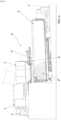
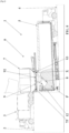
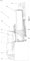
- repulsion means 8 extend vertically from the unloading opening 75, more particularly downstream of this unloading opening 75, and, on the other hand, are movable in rotation around a horizontal axis of rotation X, this between a folded position ( figure 1 , 2 , 4 has 7 , 9 ) with respect to the unloading opening 75 of the hopper 7 and a laterally deployed position with respect to this unloading opening 75 ( figure 3 And 8 ).
- Such repulsion means 8 comprise, on the one hand, a first portion 80 which extends along a first plane and which is mounted in rotation around the horizontal axis of rotation X, on the other hand, a second portion 81 which extends along a second plane which is parallel to the first plane and, d on the other hand, a connection portion 82 which connects the first portion 80 and the second portion 81 of the repulsion means 8.
- Such repulsion means 8 can take the form of a plate, in particular metallic.
- the gravity transport device 6 comprises a carriage 9, on the one hand, which is movable in translation relative to the hopper 7 and, on the other hand, on which the repulsion means 8 are mounted (more particularly reported) in rotation around the horizontal axis of rotation X.
- this carriage 9 comprises, on the one hand, a plate 92 below which the repulsion means 8 extend, on the other hand, means for mounting in rotation 93 which are configured to mount the repulsion means 8 in rotation around the horizontal axis of rotation X, this below said plate 92.
- these rotation mounting means 93 are configured to bring the repulsion means 8 in rotation around the axis of horizontal rotation X, this under said plate 92.
- said carriage 9 is movable in horizontal translation relative to the hopper 7, more particularly movable in horizontal translation relative to the unloading opening 75 of the hopper 7, this between an advanced position ( figure 2 , 3 , 7 And 8 ) in which this carriage 9 extends upstream, downstream or (and preferably) inside the unloading opening 75 and, on the other hand, a retracted position ( figure 1 , 4 has 6 And 9 ) in which this carriage 9 is at least partially (or even, and preferably, completely) offset laterally with respect to this unloading opening 75.
- this carriage 9 extends inside the unloading opening 75 of the hopper 7 and the plate 92, which this carriage 9 comprises, then closes said unloading opening 75 and, on the other hand and in position back of the carriage 9 ( figure 1 , 4 has 6 And 9 ), this plate 92 is at least partially (or even, and preferably, entirely) offset laterally with respect to the unloading opening 75 and opens said unloading opening (75).
- the gravity transport device 6 then comprises mounting means in horizontal translation 10 of the carriage 9 with respect to the hopper 7, more particularly with respect to the unloading opening 75 of this hopper 7.
- These horizontal translation mounting means 10 comprise, on the one hand, two rails which are horizontal, parallel and positioned on either side of the unloading opening 75 and, on the other hand, means bearings (not shown) or sliding means (notably in the form of pads and/or not shown), which laterally equip the carriage 9 (more particularly the plate 92), and which roll or which slide inside the rails .
- the gravity transport device 6 also comprises means for driving the carriage 9 in horizontal translation 11 with respect to the hopper 7, more particularly with respect to the unloading opening 75 of this hopper 7.
- These horizontal translation drive means 11 can be of the pneumatic or electric or (and preferably) hydraulic type.
- these drive means in horizontal translation 11 comprise, on the one hand, an arm 110 which is articulated and which is connected to said carriage 9 as well as to one of the rails or to a crosspiece which connects the two rails of the means for mounting in horizontal translation 10 and, on the other hand, actuating means (not shown) of this arm 110.
- actuating means can take the form of a cylinder (hydraulic, pneumatic or electric) or an electric motor.
- these means for driving in horizontal translation 11 can comprise at least one jack, more particularly of the pneumatic, electric or (and preferably) hydraulic type.
- a cylinder is connected to said carriage 9 (more particularly to the plate 92) as well as to a fixed element of the gravity transport device 6, in particular to one of the rails of the means for mounting in horizontal translation 10 or to a crosspiece which connects the two rails of the mounting means in horizontal translation 10.
- the repulsion means 8 are rotatable around the horizontal axis of rotation X and are rotatably mounted on the carriage 9 (more particularly rotatably mounted below the plate 92 of this carriage 9, in particular reported in rotation under this plate 92), this around this horizontal axis of rotation X.
- the gravity transport device 6 can then comprise, on the one hand, means for raising the angle between the repulsion means 8 and the carriage 9 (more particularly between the repulsion means 8 and the plate 92 of this carriage 9). These means for detecting such an angle may consist of at least one angular sensor.
- the gravity transport device 6 then also comprises control means which are configured to control the drive means 11 in horizontal translation of the carriage 9, this depending on the raised angle (by said means for raising the angle) between these repulsion means 8 and this carriage 9.
- control means can then be configured to control the drive means in horizontal translation 11 when the raised angle is less than a determined angle.
- This determined angle may correspond to the maximum angle between these repulsion means 8 and this carriage 9. The fact that the raised angle is less than this determined angle then indicates the presence of a determined quantity of product, which is loaded in the transport vehicle 5, and which opposes the action of the repulsion means 8.
- the control of the drive means in horizontal translation 11 then makes it possible to drive the carriage 9 (more particularly from forward position and in the direction of the retracted position) and, therefore, the repulsion means 8 which, when they adopt a laterally deployed position with respect to the unloading opening 75, push the product laterally with respect to said unloading opening 75 (or even laterally with respect to the hopper 7), more particularly towards the front of the transport vehicle 5. This makes it possible to optimize the loading of this transport vehicle 5.
- the gravity transport device 6 then also comprises means for driving in rotation 12 around the horizontal axis of rotation X of the repulsion means 8 with respect to the carriage 9, more particularly with respect to the tray 92 of this carriage 9.
- Such rotation drive means 12 can be of the pneumatic, electric or (and preferably) hydraulic type. Such rotational drive means 12 are positioned below the plate 92 of the carriage 9 and/or are interposed between the carriage 9 (more particularly between the plate 92 of this carriage 9) and the repulsion means 8.
- these rotational drive means 12 comprise, on the one hand, an arm 120 which is articulated and which is connected to the carriage 9 (more particularly to the plate 92) as well as to the means of repulsion 8 (more particularly to the second portion 81 of these repulsion means 8) and, on the other hand, actuating means 121 of this arm.
- said arm 120 comprises, on the one hand, a first portion of arm 120 which is mounted in rotation on the carriage 9 (more particularly mounted in rotation below the plate 92, in particular attached in rotation under this plate 92), on the other hand, a second arm portion 120 which is rotatably mounted on the repulsion means 8 (more particularly on the second portion 81 of these repulsion means 8) and, on the other hand again, articulation means which are configured to articulate the first arm portion 120 and the second arm portion 120 relative to each other while the actuating means 121 of this arm 120 are configured to drive the first portion arm 120 and the second arm portion 120, this in rotation relative to each other.
- Such actuating means 121 can take the form of a pneumatic, electric or (and preferably) hydraulic cylinder.
- the gravity transport device 6 may also comprise, on the one hand, means for raising the pressure of a hydraulic fluid of the rotational drive means 12 (such means for raising such a pressure may be constituted by at least one pressure sensor) and, on the other hand, control means which are configured to control the drive means in horizontal translation 11, this according to the pressure detected (by said means for raising the pressure) of the hydraulic fluid of the rotary drive means 12.
- control means can then be configured to control the drive means in horizontal translation 11 when the pressure detected is greater than a determined pressure.
- the fact that the pressure recorded is greater than this determined pressure indicates the presence of a determined quantity of product, which is loaded into the transport vehicle 5, and which opposes the action of the repulsion means 8
- the control of the drive means in horizontal translation 11 then makes it possible to drive the carriage 9 (more particularly from the advanced position and in the direction of the retracted position) and, therefore, the repulsion means 8 which, when they adopt a laterally deployed position with respect to the unloading opening 75, push the product laterally with respect to said unloading opening 75 (or even laterally with respect to the hopper 7), more particularly towards the front of the transport vehicle 5. This optimizes the loading of this transport vehicle 5.
- the carriage 9 (more particularly the plate 92 of this carriage 9) comprises a housing 90 inside which is retracted at least part of the rotation drive means 12 (more particularly the arm 120 and / or the actuating means 121 that comprise these rotational drive means 12) of the repulsion means 8.
- carriage 9 comprises another housing 91 inside which retracts at least the first portion 80 that comprises the repulsion means 8, or even the connection portion 82 that these repulsion means comprise 8.
- the invention relates to a transfer installation 1 of at least one bulk product P.
- Such a transfer installation 1 for at least one bulk product P then also comprises at least one transport vehicle 5 for at least one bulk product P.
- a transport vehicle 5 moves on the loading dock 4, in particular so that at least a part of this transport vehicle 5 is positioned below the gravity transport device 6 (more particularly below the hopper 7, in particular below the unloading opening 75), this with a view to loading this transport vehicle 5 with said at least one bulk product P from the gravity transport device 6.
- the gravity transport device 6 has at least some of the characteristics described above.
- the transport vehicle 5 comprises a moving floor 50, more particularly an alternating moving floor (FMA), as well as means for actuating this moving floor 50, these actuating means being pneumatic, electric or (and preferably) hydraulic type.
- a transport vehicle 5 can then comprise a skip, which is (at least partly) open at the top, and which comprises such a moving floor 50, more particularly an alternating moving floor (FMA).
- a transport vehicle 5 may consist of a semi-trailer.
- said transfer installation 1 comprises, on the one hand, means for raising the angle between the repulsion means 8 and the carriage 9 (more particularly between the repulsion means 8 and the plate 92 of this cart 9). These means for detecting such an angle may consist of at least one angular sensor.
- said transfer installation 1 then also comprises control means which are configured to control the means for actuating the moving floor 50, this depending on the raised angle (by the means for raising the angle) between these repulsion means 8 and this carriage 9.
- the means for raising the angle and/or the control means may correspond to the means for raising the angle and/or to the control means described above and which the gravity transport device 6 comprises. .
- control means can then be configured to control the means for actuating the moving floor 50 when the raised angle is less than a determined angle.
- This determined angle can, as described above, correspond to the maximum angle between these repulsion means 8 and this carriage 9.
- the fact that the raised angle is less than this determined angle indicates, here again and as described above, the presence of a determined quantity of product, which is loaded in the transport vehicle 5, and which opposes the action of the repulsion means 8.
- the control of the moving floor actuating means allows , then, to push the product laterally with respect to said unloading opening 75 (or even laterally with respect to the hopper 7), more particularly towards the front of the transport vehicle 5. This makes it possible to optimize the loading of this transport vehicle 5.
- the transfer installation 1 comprises, on the other hand, a hydraulic unit, on the other hand again, a first hydraulic circuit which connects said hydraulic unit and at least the rotation drive means 12 (or even the horizontal translation drive means 11) and, on the other hand also, a second hydraulic circuit which connects said hydraulic unit and the moving floor actuating means 50.
- the transfer installation 1 comprises, on the one hand, means for raising the pressure of a hydraulic fluid inside the first hydraulic circuit (such means for raising such a pressure can be constituted by at least one pressure sensor) and, on the other hand, control means which are configured to control the means for actuating the moving floor 50, this according to the pressure detected (by the means for raise the pressure) of the hydraulic fluid inside the first hydraulic circuit.
- the means for raising the pressure and/or the control means may correspond to the means for raising the pressure and/or the control means described above and which the gravity transport device 6 comprises.
- control means can then be configured to control the means for actuating moving floor 50 when the pressure detected is greater than a determined pressure.
- the fact that the pressure detected is greater than this determined pressure indicates, then and as described above, the presence of a determined quantity of product, which is loaded into the transport vehicle 5, and which opposes the action of the repulsion means 8.
- the control of the moving floor actuating means 50 then makes it possible to push the product laterally with respect to said unloading opening 75 (or even laterally with respect to the hopper 7), more particularly towards the front of the transport vehicle 5. This makes it possible to optimize the loading of this transport vehicle 5.
- control means can still be configured to control the drive means 11 in horizontal translation of the carriage 9, this depending on the angle raised between the repulsion means 8 and the carriage 9 (more particularly between the repulsion means 8 and the plate 92 of this carriage 9) and/or depending on the pressure reading of the hydraulic fluid inside the first hydraulic circuit.
- control means can then be configured to control the drive means 11 in horizontal translation of the carriage 9 in the manner described above, in particular when the raised angle is less than a determined angle and/ or when the pressure detected is greater than a determined pressure, this depending on the same causes and with the same effects as described above.
- control means can be configured to control the drive means in horizontal translation 11, this concomitantly with the control of the moving floor actuating means 50.
- the transfer installation 1 (more particularly the gravity transport device 6 that this transfer installation 1 comprises) may also comprise means for detecting the position of the carriage 9 (more particularly of the plate 92 of this carriage 9 ) relative to the hopper 7 and/or relative to the transport vehicle 5.
- detection means may consist of at least one linear sensor.
Landscapes
- Engineering & Computer Science (AREA)
- Mechanical Engineering (AREA)
- Filling Or Emptying Of Bunkers, Hoppers, And Tanks (AREA)
- Loading Or Unloading Of Vehicles (AREA)
Applications Claiming Priority (1)
| Application Number | Priority Date | Filing Date | Title |
|---|---|---|---|
| FR2100476A FR3118957B1 (fr) | 2021-01-19 | 2021-01-19 | Dispositif de transport gravitaire |
Publications (3)
| Publication Number | Publication Date |
|---|---|
| EP4029680A1 EP4029680A1 (fr) | 2022-07-20 |
| EP4029680C0 EP4029680C0 (fr) | 2023-08-30 |
| EP4029680B1 true EP4029680B1 (fr) | 2023-08-30 |
Family
ID=75539484
Family Applications (1)
| Application Number | Title | Priority Date | Filing Date |
|---|---|---|---|
| EP22150457.4A Active EP4029680B1 (fr) | 2021-01-19 | 2022-01-06 | Dispositif de transport gravitaire et installation de transfert d'au moins un produit en vrac |
Country Status (4)
| Country | Link |
|---|---|
| EP (1) | EP4029680B1 (pl) |
| ES (1) | ES2963739T3 (pl) |
| FR (1) | FR3118957B1 (pl) |
| PL (1) | PL4029680T3 (pl) |
Families Citing this family (1)
| Publication number | Priority date | Publication date | Assignee | Title |
|---|---|---|---|---|
| CN117262648B (zh) * | 2023-10-13 | 2024-07-16 | 南通四通林业机械制造安装有限公司 | 一种具有辅助结构的输送装置 |
Family Cites Families (5)
| Publication number | Priority date | Publication date | Assignee | Title |
|---|---|---|---|---|
| JPS59500953A (ja) * | 1982-06-03 | 1984-05-31 | エドモンズ,ジョン・ジョ−ジ | 密集詰め込み装置 |
| DE9309294U1 (de) * | 1993-06-22 | 1993-08-19 | Giehl, Joachim, 80686 München | Dosier- und Fülleinrichtung für fließfähige Nahrung insbesondere Babynahrung |
| CN2567180Y (zh) * | 2002-08-20 | 2003-08-20 | 广州市高雅洁环境服务有限公司 | 顶置压缩式垃圾箱 |
| CN103950670B (zh) * | 2014-05-07 | 2016-08-24 | 海沃机械(中国)有限公司 | 一种固定式垃圾压缩设备 |
| FR3098206B1 (fr) * | 2019-07-05 | 2021-08-20 | Legras Ind | Dispositif de transport gravitaire |
-
2021
- 2021-01-19 FR FR2100476A patent/FR3118957B1/fr active Active
-
2022
- 2022-01-06 PL PL22150457.4T patent/PL4029680T3/pl unknown
- 2022-01-06 ES ES22150457T patent/ES2963739T3/es active Active
- 2022-01-06 EP EP22150457.4A patent/EP4029680B1/fr active Active
Also Published As
| Publication number | Publication date |
|---|---|
| PL4029680T3 (pl) | 2024-02-05 |
| ES2963739T3 (es) | 2024-04-01 |
| EP4029680A1 (fr) | 2022-07-20 |
| EP4029680C0 (fr) | 2023-08-30 |
| FR3118957A1 (fr) | 2022-07-22 |
| FR3118957B1 (fr) | 2023-06-23 |
Similar Documents
| Publication | Publication Date | Title |
|---|---|---|
| US9102466B2 (en) | Waste collection vehicle with bucket drive mechanism | |
| EP4029680B1 (fr) | Dispositif de transport gravitaire et installation de transfert d'au moins un produit en vrac | |
| EP3526147B1 (fr) | Système comprenant un silo et une vis balayeuse | |
| FR2944488A1 (fr) | Benne de chargement autonome destinee a recevoir une charge | |
| FR3098206A1 (fr) | Dispositif de transport gravitaire | |
| EP4538218A1 (fr) | Dispositif d'interface de manutention d'un contenant notamment d'un contenant basculant | |
| FR2945284A1 (fr) | Benne de collecte de dechets | |
| EP1516836B1 (fr) | Dispositif de vidange d'un silo à fond sensiblement plat | |
| FR3067336A1 (fr) | Conteneur de collecte de dechets | |
| FR3010989A1 (fr) | Installation de dechargement automatique d'objets d'un conteneur | |
| EP1098827A1 (fr) | Benne pour la collecte et le transport d'une charge du type dechets menagers | |
| FR3068958B1 (fr) | Conteneur pour la collecte de dechets a ouvrant actionne par transfert de masse | |
| EP2228262A1 (fr) | Dispositif d'aide au chargement et au déchargement du coffre d'un véhicule, véhicule équipé d'un tel dispositif | |
| FR2911858A1 (fr) | Dispositif elevateur-basculeur pour conteneur,notamment de pieces en vrac | |
| EP4520686A1 (fr) | Agencement de basculeur pour vider un conteneur dans une benne de collecte | |
| FR2884237A1 (fr) | Installation de transport et de manutention d'equipements de vehicule automobile | |
| EP1495994B1 (fr) | Déchetterie mobile | |
| WO2006027520A1 (fr) | Dispositif automoteur compacteur de dechets | |
| FR3153296A1 (fr) | Caisse a porte arriere automatique pour vehicule industriel | |
| FR3070969B1 (fr) | Dispositif de transport gravitaire et installation de transfert de dechets | |
| EP3441259B1 (fr) | Châssis roulant et caisse de chargement basculante et amovible | |
| EP3168173A1 (fr) | Dispositif de chargement, d'élévation et de déversement de déchets dans une benne | |
| FR2940203A1 (fr) | Equipement amovible de transport d'une charge | |
| CA2762771C (en) | Waste collection vehicle with bucket drive mechanism | |
| FR2941185A1 (fr) | Vehicule equipe d'un systeme de manutention pour contenants amovibles |
Legal Events
| Date | Code | Title | Description |
|---|---|---|---|
| PUAI | Public reference made under article 153(3) epc to a published international application that has entered the european phase |
Free format text: ORIGINAL CODE: 0009012 |
|
| STAA | Information on the status of an ep patent application or granted ep patent |
Free format text: STATUS: THE APPLICATION HAS BEEN PUBLISHED |
|
| AK | Designated contracting states |
Kind code of ref document: A1 Designated state(s): AL AT BE BG CH CY CZ DE DK EE ES FI FR GB GR HR HU IE IS IT LI LT LU LV MC MK MT NL NO PL PT RO RS SE SI SK SM TR |
|
| STAA | Information on the status of an ep patent application or granted ep patent |
Free format text: STATUS: REQUEST FOR EXAMINATION WAS MADE |
|
| 17P | Request for examination filed |
Effective date: 20220930 |
|
| RBV | Designated contracting states (corrected) |
Designated state(s): AL AT BE BG CH CY CZ DE DK EE ES FI FR GB GR HR HU IE IS IT LI LT LU LV MC MK MT NL NO PL PT RO RS SE SI SK SM TR |
|
| GRAP | Despatch of communication of intention to grant a patent |
Free format text: ORIGINAL CODE: EPIDOSNIGR1 |
|
| STAA | Information on the status of an ep patent application or granted ep patent |
Free format text: STATUS: GRANT OF PATENT IS INTENDED |
|
| INTG | Intention to grant announced |
Effective date: 20230321 |
|
| GRAS | Grant fee paid |
Free format text: ORIGINAL CODE: EPIDOSNIGR3 |
|
| GRAA | (expected) grant |
Free format text: ORIGINAL CODE: 0009210 |
|
| STAA | Information on the status of an ep patent application or granted ep patent |
Free format text: STATUS: THE PATENT HAS BEEN GRANTED |
|
| AK | Designated contracting states |
Kind code of ref document: B1 Designated state(s): AL AT BE BG CH CY CZ DE DK EE ES FI FR GB GR HR HU IE IS IT LI LT LU LV MC MK MT NL NO PL PT RO RS SE SI SK SM TR |
|
| REG | Reference to a national code |
Ref country code: GB Ref legal event code: FG4D Free format text: NOT ENGLISH |
|
| REG | Reference to a national code |
Ref country code: CH Ref legal event code: EP |
|
| REG | Reference to a national code |
Ref country code: DE Ref legal event code: R096 Ref document number: 602022000386 Country of ref document: DE |
|
| REG | Reference to a national code |
Ref country code: IE Ref legal event code: FG4D Free format text: LANGUAGE OF EP DOCUMENT: FRENCH |
|
| U01 | Request for unitary effect filed |
Effective date: 20230929 |
|
| U07 | Unitary effect registered |
Designated state(s): AT BE BG DE DK EE FI FR IT LT LU LV MT NL PT SE SI Effective date: 20231006 |
|
| PG25 | Lapsed in a contracting state [announced via postgrant information from national office to epo] |
Ref country code: GR Free format text: LAPSE BECAUSE OF FAILURE TO SUBMIT A TRANSLATION OF THE DESCRIPTION OR TO PAY THE FEE WITHIN THE PRESCRIBED TIME-LIMIT Effective date: 20231201 |
|
| PG25 | Lapsed in a contracting state [announced via postgrant information from national office to epo] |
Ref country code: IS Free format text: LAPSE BECAUSE OF FAILURE TO SUBMIT A TRANSLATION OF THE DESCRIPTION OR TO PAY THE FEE WITHIN THE PRESCRIBED TIME-LIMIT Effective date: 20231230 |
|
| PG25 | Lapsed in a contracting state [announced via postgrant information from national office to epo] |
Ref country code: RS Free format text: LAPSE BECAUSE OF FAILURE TO SUBMIT A TRANSLATION OF THE DESCRIPTION OR TO PAY THE FEE WITHIN THE PRESCRIBED TIME-LIMIT Effective date: 20230830 Ref country code: NO Free format text: LAPSE BECAUSE OF FAILURE TO SUBMIT A TRANSLATION OF THE DESCRIPTION OR TO PAY THE FEE WITHIN THE PRESCRIBED TIME-LIMIT Effective date: 20231130 Ref country code: IS Free format text: LAPSE BECAUSE OF FAILURE TO SUBMIT A TRANSLATION OF THE DESCRIPTION OR TO PAY THE FEE WITHIN THE PRESCRIBED TIME-LIMIT Effective date: 20231230 Ref country code: HR Free format text: LAPSE BECAUSE OF FAILURE TO SUBMIT A TRANSLATION OF THE DESCRIPTION OR TO PAY THE FEE WITHIN THE PRESCRIBED TIME-LIMIT Effective date: 20230830 Ref country code: GR Free format text: LAPSE BECAUSE OF FAILURE TO SUBMIT A TRANSLATION OF THE DESCRIPTION OR TO PAY THE FEE WITHIN THE PRESCRIBED TIME-LIMIT Effective date: 20231201 |
|
| U20 | Renewal fee for the european patent with unitary effect paid |
Year of fee payment: 3 Effective date: 20240123 |
|
| REG | Reference to a national code |
Ref country code: ES Ref legal event code: FG2A Ref document number: 2963739 Country of ref document: ES Kind code of ref document: T3 Effective date: 20240401 |
|
| PG25 | Lapsed in a contracting state [announced via postgrant information from national office to epo] |
Ref country code: SM Free format text: LAPSE BECAUSE OF FAILURE TO SUBMIT A TRANSLATION OF THE DESCRIPTION OR TO PAY THE FEE WITHIN THE PRESCRIBED TIME-LIMIT Effective date: 20230830 Ref country code: RO Free format text: LAPSE BECAUSE OF FAILURE TO SUBMIT A TRANSLATION OF THE DESCRIPTION OR TO PAY THE FEE WITHIN THE PRESCRIBED TIME-LIMIT Effective date: 20230830 Ref country code: CZ Free format text: LAPSE BECAUSE OF FAILURE TO SUBMIT A TRANSLATION OF THE DESCRIPTION OR TO PAY THE FEE WITHIN THE PRESCRIBED TIME-LIMIT Effective date: 20230830 Ref country code: SK Free format text: LAPSE BECAUSE OF FAILURE TO SUBMIT A TRANSLATION OF THE DESCRIPTION OR TO PAY THE FEE WITHIN THE PRESCRIBED TIME-LIMIT Effective date: 20230830 |
|
| REG | Reference to a national code |
Ref country code: DE Ref legal event code: R097 Ref document number: 602022000386 Country of ref document: DE |
|
| PLBE | No opposition filed within time limit |
Free format text: ORIGINAL CODE: 0009261 |
|
| STAA | Information on the status of an ep patent application or granted ep patent |
Free format text: STATUS: NO OPPOSITION FILED WITHIN TIME LIMIT |
|
| 26N | No opposition filed |
Effective date: 20240603 |
|
| PG25 | Lapsed in a contracting state [announced via postgrant information from national office to epo] |
Ref country code: MC Free format text: LAPSE BECAUSE OF FAILURE TO SUBMIT A TRANSLATION OF THE DESCRIPTION OR TO PAY THE FEE WITHIN THE PRESCRIBED TIME-LIMIT Effective date: 20230830 |
|
| PG25 | Lapsed in a contracting state [announced via postgrant information from national office to epo] |
Ref country code: MC Free format text: LAPSE BECAUSE OF FAILURE TO SUBMIT A TRANSLATION OF THE DESCRIPTION OR TO PAY THE FEE WITHIN THE PRESCRIBED TIME-LIMIT Effective date: 20230830 |
|
| PG25 | Lapsed in a contracting state [announced via postgrant information from national office to epo] |
Ref country code: IE Free format text: LAPSE BECAUSE OF NON-PAYMENT OF DUE FEES Effective date: 20240106 |
|
| PG25 | Lapsed in a contracting state [announced via postgrant information from national office to epo] |
Ref country code: IE Free format text: LAPSE BECAUSE OF NON-PAYMENT OF DUE FEES Effective date: 20240106 |
|
| U20 | Renewal fee for the european patent with unitary effect paid |
Year of fee payment: 4 Effective date: 20250115 |
|
| PG25 | Lapsed in a contracting state [announced via postgrant information from national office to epo] |
Ref country code: CY Free format text: LAPSE BECAUSE OF FAILURE TO SUBMIT A TRANSLATION OF THE DESCRIPTION OR TO PAY THE FEE WITHIN THE PRESCRIBED TIME-LIMIT; INVALID AB INITIO Effective date: 20220106 |
|
| REG | Reference to a national code |
Ref country code: CH Ref legal event code: PL |
|
| PG25 | Lapsed in a contracting state [announced via postgrant information from national office to epo] |
Ref country code: CH Free format text: LAPSE BECAUSE OF NON-PAYMENT OF DUE FEES Effective date: 20250131 |
|
| U20 | Renewal fee for the european patent with unitary effect paid |
Year of fee payment: 5 Effective date: 20251103 |
|
| PG25 | Lapsed in a contracting state [announced via postgrant information from national office to epo] |
Ref country code: TR Free format text: LAPSE BECAUSE OF FAILURE TO SUBMIT A TRANSLATION OF THE DESCRIPTION OR TO PAY THE FEE WITHIN THE PRESCRIBED TIME-LIMIT Effective date: 20230830 |
|
| PGFP | Annual fee paid to national office [announced via postgrant information from national office to epo] |
Ref country code: PL Payment date: 20251218 Year of fee payment: 5 |
|
| PGFP | Annual fee paid to national office [announced via postgrant information from national office to epo] |
Ref country code: GB Payment date: 20260127 Year of fee payment: 5 |
|
| PGFP | Annual fee paid to national office [announced via postgrant information from national office to epo] |
Ref country code: ES Payment date: 20260209 Year of fee payment: 5 |