EP4029619B1 - Tragbare schneideanlage - Google Patents
Tragbare schneideanlage Download PDFInfo
- Publication number
- EP4029619B1 EP4029619B1 EP22151101.7A EP22151101A EP4029619B1 EP 4029619 B1 EP4029619 B1 EP 4029619B1 EP 22151101 A EP22151101 A EP 22151101A EP 4029619 B1 EP4029619 B1 EP 4029619B1
- Authority
- EP
- European Patent Office
- Prior art keywords
- cutting line
- main table
- lazy susan
- portable cutting
- frame
- Prior art date
- Legal status (The legal status is an assumption and is not a legal conclusion. Google has not performed a legal analysis and makes no representation as to the accuracy of the status listed.)
- Active
Links
Images




Classifications
-
- B—PERFORMING OPERATIONS; TRANSPORTING
- B21—MECHANICAL METAL-WORKING WITHOUT ESSENTIALLY REMOVING MATERIAL; PUNCHING METAL
- B21F—WORKING OR PROCESSING OF METAL WIRE
- B21F45/00—Wire-working in the manufacture of other particular articles
- B21F45/006—Wire-working in the manufacture of other particular articles of concrete reinforcement fibres
-
- B—PERFORMING OPERATIONS; TRANSPORTING
- B21—MECHANICAL METAL-WORKING WITHOUT ESSENTIALLY REMOVING MATERIAL; PUNCHING METAL
- B21F—WORKING OR PROCESSING OF METAL WIRE
- B21F11/00—Cutting wire
-
- B—PERFORMING OPERATIONS; TRANSPORTING
- B21—MECHANICAL METAL-WORKING WITHOUT ESSENTIALLY REMOVING MATERIAL; PUNCHING METAL
- B21C—MANUFACTURE OF METAL SHEETS, WIRE, RODS, TUBES, PROFILES OR LIKE SEMI-MANUFACTURED PRODUCTS OTHERWISE THAN BY ROLLING; AUXILIARY OPERATIONS USED IN CONNECTION WITH METAL-WORKING WITHOUT ESSENTIALLY REMOVING MATERIAL
- B21C47/00—Winding-up, coiling or winding-off metal wire, metal band or other flexible metal material characterised by features relevant to metal processing only
- B21C47/02—Winding-up or coiling
- B21C47/04—Winding-up or coiling on or in reels or drums, without using a moving guide
- B21C47/045—Winding-up or coiling on or in reels or drums, without using a moving guide in rotating drums
-
- B—PERFORMING OPERATIONS; TRANSPORTING
- B21—MECHANICAL METAL-WORKING WITHOUT ESSENTIALLY REMOVING MATERIAL; PUNCHING METAL
- B21C—MANUFACTURE OF METAL SHEETS, WIRE, RODS, TUBES, PROFILES OR LIKE SEMI-MANUFACTURED PRODUCTS OTHERWISE THAN BY ROLLING; AUXILIARY OPERATIONS USED IN CONNECTION WITH METAL-WORKING WITHOUT ESSENTIALLY REMOVING MATERIAL
- B21C47/00—Winding-up, coiling or winding-off metal wire, metal band or other flexible metal material characterised by features relevant to metal processing only
- B21C47/16—Unwinding or uncoiling
- B21C47/18—Unwinding or uncoiling from reels or drums
-
- B—PERFORMING OPERATIONS; TRANSPORTING
- B21—MECHANICAL METAL-WORKING WITHOUT ESSENTIALLY REMOVING MATERIAL; PUNCHING METAL
- B21F—WORKING OR PROCESSING OF METAL WIRE
- B21F23/00—Feeding wire in wire-working machines or apparatus
-
- B—PERFORMING OPERATIONS; TRANSPORTING
- B65—CONVEYING; PACKING; STORING; HANDLING THIN OR FILAMENTARY MATERIAL
- B65D—CONTAINERS FOR STORAGE OR TRANSPORT OF ARTICLES OR MATERIALS, e.g. BAGS, BARRELS, BOTTLES, BOXES, CANS, CARTONS, CRATES, DRUMS, JARS, TANKS, HOPPERS, FORWARDING CONTAINERS; ACCESSORIES, CLOSURES, OR FITTINGS THEREFOR; PACKAGING ELEMENTS; PACKAGES
- B65D88/00—Large containers
- B65D88/02—Large containers rigid
- B65D88/12—Large containers rigid specially adapted for transport
- B65D88/121—ISO containers
-
- E—FIXED CONSTRUCTIONS
- E04—BUILDING
- E04C—STRUCTURAL ELEMENTS; BUILDING MATERIALS
- E04C5/00—Reinforcing elements, e.g. for concrete; Auxiliary elements therefor
- E04C5/08—Members specially adapted to be used in prestressed constructions
- E04C5/12—Anchoring devices
- E04C5/122—Anchoring devices the tensile members are anchored by wedge-action
-
- Y—GENERAL TAGGING OF NEW TECHNOLOGICAL DEVELOPMENTS; GENERAL TAGGING OF CROSS-SECTIONAL TECHNOLOGIES SPANNING OVER SEVERAL SECTIONS OF THE IPC; TECHNICAL SUBJECTS COVERED BY FORMER USPC CROSS-REFERENCE ART COLLECTIONS [XRACs] AND DIGESTS
- Y10—TECHNICAL SUBJECTS COVERED BY FORMER USPC
- Y10T—TECHNICAL SUBJECTS COVERED BY FORMER US CLASSIFICATION
- Y10T29/00—Metal working
- Y10T29/51—Plural diverse manufacturing apparatus including means for metal shaping or assembling
- Y10T29/5124—Plural diverse manufacturing apparatus including means for metal shaping or assembling with means to feed work intermittently from one tool station to another
- Y10T29/5135—Endless belt
-
- Y—GENERAL TAGGING OF NEW TECHNOLOGICAL DEVELOPMENTS; GENERAL TAGGING OF CROSS-SECTIONAL TECHNOLOGIES SPANNING OVER SEVERAL SECTIONS OF THE IPC; TECHNICAL SUBJECTS COVERED BY FORMER USPC CROSS-REFERENCE ART COLLECTIONS [XRACs] AND DIGESTS
- Y10—TECHNICAL SUBJECTS COVERED BY FORMER USPC
- Y10T—TECHNICAL SUBJECTS COVERED BY FORMER US CLASSIFICATION
- Y10T29/00—Metal working
- Y10T29/51—Plural diverse manufacturing apparatus including means for metal shaping or assembling
- Y10T29/5136—Separate tool stations for selective or successive operation on work
- Y10T29/5137—Separate tool stations for selective or successive operation on work including assembling or disassembling station
- Y10T29/5142—Separate tool stations for selective or successive operation on work including assembling or disassembling station and means to sever work from supply
-
- Y—GENERAL TAGGING OF NEW TECHNOLOGICAL DEVELOPMENTS; GENERAL TAGGING OF CROSS-SECTIONAL TECHNOLOGIES SPANNING OVER SEVERAL SECTIONS OF THE IPC; TECHNICAL SUBJECTS COVERED BY FORMER USPC CROSS-REFERENCE ART COLLECTIONS [XRACs] AND DIGESTS
- Y10—TECHNICAL SUBJECTS COVERED BY FORMER USPC
- Y10T—TECHNICAL SUBJECTS COVERED BY FORMER US CLASSIFICATION
- Y10T29/00—Metal working
- Y10T29/51—Plural diverse manufacturing apparatus including means for metal shaping or assembling
- Y10T29/5136—Separate tool stations for selective or successive operation on work
- Y10T29/5137—Separate tool stations for selective or successive operation on work including assembling or disassembling station
- Y10T29/5143—Separate tool stations for selective or successive operation on work including assembling or disassembling station and means to machine product
- Y10T29/5145—Separate tool stations for selective or successive operation on work including assembling or disassembling station and means to machine product to sever product to length
Definitions
- the present disclosure is directed to a portable cutting line.
- Many structures are built using concrete, including, for instance, buildings, parking structures, apartments, condominiums, hotels, mixed-use buildings, casinos, hospitals, medical buildings, government buildings, research/academic institutions, industrial buildings, malls, bridges, pavement, tanks, reservoirs, silos, foundations, sports courts, and other structures.
- Pre-stressed concrete is structural concrete in which internal stresses are introduced to reduce potential tensile stresses in the concrete resulting from applied loads. This can be accomplished by two methods-pre-tensioned pre-stressing and post-tensioned pre-stressing.
- post-tensioning concrete the pre-stressing assembly is tensioned after the concrete has cured to a specified strength.
- the pre-stressing assembly commonly known as a tendon, may include for example and without limitation, anchorages, one or more strands, and sheaths or ducts surrounding the strand(s). A strand may be tensioned between a pair of anchors, which are embedded in the concrete.
- the strand may be formed from a metal or composite or any suitable material exhibiting tensile strength, including, for example and without limitation, reinforcing steel, single wire cable, or multi-wire cable.
- the strand is typically fixedly coupled to a fixed anchorage positioned at one end of the tendon, the so-called “fixed end”, and is adapted to be stressed at the other anchor, the "stressing end" of the tendon.
- the strand is generally retained in each anchor by one or more wedges that engage a tapered recess in the anchor body so that when the strand is placed under tension, the wedges engage the strand more tightly.
- One end of the strand extends through the stressing end anchor and out of the concrete body in which the anchor is embedded.
- a pocket former is placed around the strand before the concrete is poured, which results in a pocket in the cured concrete.
- the end of the strand extends through and outwardly from the pocket.
- JP H03 180234 A refers to a coiled reinforcing bar bending device
- US 2018/311714 A1 refers to a tendon processing system including at least one tub for supporting a tendon and an indexing assembly for moving the tub.
- WO 2019/185636 A1 refers to a transport system for a wire or a plate.
- the present disclosure provides for a portable cutting line.
- the portable cutting line includes a frame and a lazy susan.
- the portable cutting line also includes a cutting line main table, the cutting line main table operatively connected to the lazy susan and one or more tubs, the tubs operatively connected to the cutting line main table.
- the lazy susan, the cutting line main table, and the one or more tubs are positioned within the frame when in transport position.
- a mill may supply a spool of cable.
- the cable may be single or multi-strand.
- the mill may extrude the cable, apply grease, and sheathing, and coil.
- Certain embodiments of the present disclosure are directed to a portable cutting line for forming a strand from the spool supplied by the mill.
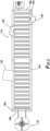
- FIG. 1 depicts portable cutting line 100.
- Portable cutting line 100 includes lazy susan 110, cutting line main table 130, and at least one tub 140.
- Lazy susan 110 includes turntable 112 and may include retaining arms 114.
- Lazy susan 110 is adapted to receive the spool of cable.
- Lazy susan 110 may be driven or not driven.
- lazy susan 110 When driven, lazy susan 110 may include driving mechanism 116 such as a motor to turn lazy susan 110 and thereby unspool the cable for use in cutting line main table 130. When not driven, lazy susan 110 may turn and unspool the cable as the cable is pulled by cutting line main table 130.
- driving mechanism 116 such as a motor to turn lazy susan 110 and thereby unspool the cable for use in cutting line main table 130.
- lazy susan 110 may turn and unspool the cable as the cable is pulled by cutting line main table 130.
- Lazy susan 110 is operatively connected to cutting line main table 130.
- Cutting line main table 130 is adapted to receive the cable from lazy susan 110 and shear the cable to form a strand.
- cutting line main table 130 includes catapuller 132 and shear 134.
- Catapuller 132 may be any mechanism adapted to pull the cable from lazy susan 110 and feed the cable to shear 134. As shown in FIG. 1A , catapuller 132 may include catapuller bodies 1020. Catapuller bodies 1020 are separated by gap 1040, through which the cable may be pulled by catapuller 132. Each catapuller body 1020 includes drive mechanism 1060, which, as shown in FIG. 2 , may be a drive wheel, and retaining wheel 1080. Loop 1100 is positioned around drive mechanism 1060 and retaining wheel 1080. Loop 1100 may be, for example, a belt or chain. As drive mechanism 1060 rotates, loop 1100 is pulled through gap 1040, causing the cable to be pulled through catapuller 132.
- Shear 134 may include at least one sharp edge for cutting or shearing the cable to form the strand.
- shear 134 may include a rotating blade and a fixed blade. Shear 134 may be operated manually, electrically, pneumatically, or hydraulically, for example.
- cutting line main table 130 may include roller box 131.
- Roller box 131 may align the cable upstream of catapuller 132.
- Cutting line main table 130 may include line counter 135.
- Line counter 135 may measure the length of the cable as pulled through catapuller 132.
- cutting line main table 130 may include tub selector 136, such as when portable cutting line 100 includes more than one tub 140. Tub selector 136 determines which of the plurality of tubs 140 the strand is transferred.
- Portable cutting line 100 includes one or more tubs 140.
- One or more tubs 140 are operatively connected to and adapted to receive the strand from cutting line main table 130 and spool the strand.
- tubs 140 include tub base 142 and strand receiving area 144.
- Tub base 142 may rotate so as to spool strands received from cutting line main table 130. Rotation of tub base 142 may be driven, i.e., turned manually, electrically, pneumatically, or hydraulically.
- Strand receiving area 144 may include one or more sides 146 to hold the strand spool in place.
- Portable cutting line 100 may also include power source 120.
- Power source 120 may provide power to, and be operatively connected to, lazy susan 110, cutting line main table 130, tubs 140, and, in certain embodiments, seater station 150.
- Power source 120 may supply electrical power, air for pneumatic power, or hydraulic power.
- power source 120 is a generator for providing electrical power.
- portable cutting line 100 may include seater station 150.
- Seater station 150 may be used to fasten an anchor to one end of the strand. In other embodiments, seater station 150 is not included in portable cutting line 100.
- Portable cutting line 100 includes a transport position, as shown in FIGs. 6- 8 , and an operation position, as shown in FIGs. 1-5 . In the transport position, portable cutting line 100 is positioned within frame 160. Frame 160 is a shipping container. In the transport position, all elements of portable cutting line 100 are positioned within frame 160.
- lazy susan 110 may be moved along the long axis of frame 160 to increase the distance between cutting line main table 130 and lazy susan 110, as shown in FIGs. 1 - 5 .
- power source 120 may swing to be outside side 162 of frame 160 defined by the long axis of frame 160, so as to remove power source 120 from the path of the cable between lazy susan 110 and cutting line main table 130.
- tubs 140 may swing to be partially or completely outside sides 162 and 164 (also defined by the long axis of frame 160).
- seater station 150 may be moved along the long axis of frame 160 to increase the distance between seater station 150 and one or more tubs 140.
- FIGs. 1 and 4 depict an embodiment for the operation position of portable cutting line 100.
- Portable cutting line 100 includes extension 170 positioned at least partially within frame 160.
- Extension 170 includes center rail 171.
- Lazy susan rail 172 is mechanically connected to lazy susan 110 and extends from center rail 171, thereby moving lazy susan 110 from the transport position to the operation position.
- Extension 170 may also include generator rotator arm 174 rotatably attached to center rail 171 and mechanically connected to power source 120. By rotating generator rotator arm 174 relative to center rail 171, power source 120 may be swung into the operation position.
- extension 170 may include one or more tub rotator arms 176 rotatably attached to center rail 171 and mechanically connected to tubs 140.
- extension 170 may include seater station rail 178.
- Seater station rail 178 may extend from center rail 171 or be rotatably connected to center rail 171, for example and mechanically connected to seater station 150. By extending or rotating seater station rail 178, seater station 150 may be moved into the operation position.
- the frame 160 is a shipping container, and ends 180 of frame 160 are removable, or as shown in FIG. 2 , be adapted to swing on hinge 182 to expose an interior of frame 160 and allow lazy susan 110 and seater station 150 to move to the operation position. Further, as shown in FIG. 3 , sides 190 of frame 160 may be removable or may flip up to expose the interior of frame 160 and to allow tubs 140 and power source 120 to be swung into the operation position.
Landscapes
- Engineering & Computer Science (AREA)
- Mechanical Engineering (AREA)
- Processing Of Stones Or Stones Resemblance Materials (AREA)
- Life Sciences & Earth Sciences (AREA)
- Forests & Forestry (AREA)
- Surgical Instruments (AREA)
- Polishing Bodies And Polishing Tools (AREA)
- Harvesting Machines For Root Crops (AREA)
- Electric Cable Installation (AREA)
Claims (11)
- Tragbare Schneideanlage (100), wobei die tragbare Schneideanlage (100) umfasst:ein Gestell (160);einen Drehkranz (110), der dazu ausgelegt ist, eine Kabelspule aufzunehmen;einen Schneideanlagen-Haupttisch (130), der dazu ausgelegt ist, die Kabelspule von dem Drehkranz (110) aufzunehmen und das Kabel zu scheren, um einen Strang zu bilden, wobei der Schneideanlagen-Haupttisch (130) operativ mit dem Drehkranz (110) verbunden ist; undeine oder mehrere Wannen (140), die dazu ausgelegt sind, den Strang von dem Schneideanlagen-Haupttisch (130) aufzunehmen und den Strang aufzuspulen, wobei die Wannen (140) operativ mit dem Schneideanlagen-Haupttisch (130) verbunden sind;wobei der Drehkranz (110), der Schneideanlagen-Haupttisch (130) und die eine oder mehreren Wannen (140) innerhalb des Gestells (160), wenn in einer Transportposition, positioniert sind; undferner umfassend eine Verlängerung (170), die mindestens teilweise innerhalb des Gestells (160) positioniert ist, wobei die Verlängerung eine Mittelschiene (171) und eine Drehkranzschiene (172), die sich von der Mittelschiene (171) erstreckt und mechanisch mit dem Drehkranz (110) verbunden ist, beinhaltet, wobei die Drehkranzschiene (172) dazu konfiguriert ist, sich von der Mittelschiene (171) zu erstrecken, wodurch der Drehkranz (110) von der Transportposition in eine Betriebsposition bewegt wird;wobei das Gestell (160) ein Versandcontainer ist und wobei das Gestell (160) Enden (160) beinhaltet, die dazu ausgelegt sind, abnehmbar zu sein, oder dazu ausgelegt sind, auf einem Scharnier zu schwenken, um einen Innenraum des Gestells (160) freizulegen und es dem Drehkranz (110) zu ermöglichen, sich in die Betriebsposition zu bewegen.
- Tragbare Schneideanlage (100) nach Anspruch 1, wobei der Drehkranz (110) einen Drehteller (112) umfasst; optional, wobei der Drehteller (112) angetrieben oder nicht angetrieben ist.
- Tragbare Schneideanlage (100) nach einem der Ansprüche 1 oder 2, wobei der Schneideanlagen-Haupttisch (130) eine Ziehvorrichtung (132) umfasst.
- Tragbare Schneideanlage (100) nach einem der Ansprüche 1 bis 3, wobei der Schneideanlagen-Haupttisch (130) eine Schere (134) umfasst; optional, wobei die Schere (134) ein rotierendes Messer und ein festes Messer beinhaltet.
- Tragbare Schneideanlage (100) nach einem der Ansprüche 1 bis 4, wobei der Schneideanlagen-Haupttisch (130) einen Anlagenzähler (135) umfasst, der dazu konfiguriert ist, die Länge des Kabels, wie durch eine Ziehvorrichtung (132) oder einen Wannenselektor (136) hindurch gezogen, zu messen.
- Tragbare Schneideanlage (100) nach einem der Ansprüche 1 bis 5, ferner umfassend eine Absetzstation (150), die dazu konfiguriert ist, einen Anker an einem Ende des Strangs zu befestigen, wobei die Absetzstation (150) operativ mit dem Schneideanlagen-Haupttisch (130) verbunden ist.
- Tragbare Schneideanlage (100) nach einem der Ansprüche 1 bis 6, ferner umfassend eine Energiequelle (120), wobei die Energiequelle (120) dazu ausgelegt ist, elektrische Energie, Luft für pneumatische Energie oder hydraulische Energie an eines oder mehrere des Drehkranzes (110), des Schneideanlagen-Haupttischs (130), der Wannen (140) und der Absetzstation (150) zu liefern.
- Tragbare Schneideanlage (100) nach Anspruch 7, wobei die Verlängerung (170) einen Generator-Rotatorarm (174) beinhaltet, der mechanisch mit der Energiequelle (120) verbunden ist und drehbar mit der Mittelschiene (171) verbunden ist.
- Tragbare Schneideanlage (100) nach Anspruch 8, wobei die Verlängerung (170) einen oder mehrere Wannen-Rotatorarme (176) beinhaltet, die mechanisch mit der einen oder mehreren Wannen (140) verbunden sind und drehbar mit der Mittelschiene (171) verbunden sind.
- Tragbare Schneideanlage (100) nach einem der Ansprüche 6 bis 9, wobei die Verlängerung (170) eine Absetzstationsschiene (178) beinhaltet, die mechanisch mit der Absetzstation (150) verbunden ist und drehbar mit der Mittelschiene (171) verbunden ist oder sich von dieser erstreckt.
- Tragbare Schneideanlage (100) nach Anspruch 1, wobei das Gestell (160) Seiten (190) beinhaltet, die dazu ausgelegt sind, abnehmbar zu sein, oder dazu ausgelegt sind, nach oben zu klappen.
Applications Claiming Priority (2)
| Application Number | Priority Date | Filing Date | Title |
|---|---|---|---|
| US202163136949P | 2021-01-13 | 2021-01-13 | |
| US17/572,766 US12226817B2 (en) | 2021-01-13 | 2022-01-11 | Portable cutting line |
Publications (2)
| Publication Number | Publication Date |
|---|---|
| EP4029619A1 EP4029619A1 (de) | 2022-07-20 |
| EP4029619B1 true EP4029619B1 (de) | 2024-04-24 |
Family
ID=79927412
Family Applications (1)
| Application Number | Title | Priority Date | Filing Date |
|---|---|---|---|
| EP22151101.7A Active EP4029619B1 (de) | 2021-01-13 | 2022-01-12 | Tragbare schneideanlage |
Country Status (4)
| Country | Link |
|---|---|
| US (1) | US12226817B2 (de) |
| EP (1) | EP4029619B1 (de) |
| AU (1) | AU2022200165B2 (de) |
| ES (1) | ES2981456T3 (de) |
Families Citing this family (3)
| Publication number | Priority date | Publication date | Assignee | Title |
|---|---|---|---|---|
| EP4431426A3 (de) * | 2018-03-27 | 2024-11-27 | Alleima GmbH | Transportsystem für ein rohr und verfahren zum ausliefern eines rohrs |
| US11858728B2 (en) * | 2021-10-29 | 2024-01-02 | Scott Carrington | Container anchoring base |
| AU2023217639A1 (en) * | 2022-02-09 | 2024-09-05 | Felix Sorkin | Automated systems and methods for post-tension tendon manufacture and coiling |
Family Cites Families (10)
| Publication number | Priority date | Publication date | Assignee | Title |
|---|---|---|---|---|
| US224942A (en) * | 1880-02-24 | morgan | ||
| US2275563A (en) * | 1939-03-17 | 1942-03-10 | Aluminum Co Of America | Apparatus for continuously processing wire |
| JPH084865B2 (ja) | 1989-12-08 | 1996-01-24 | 石原機械工業株式会社 | コイル状鉄筋の曲げ加工装置、取出し方法、キャラバンカーおよびコイル状鉄筋の曲げ加工方法 |
| US20140373587A1 (en) * | 2013-06-24 | 2014-12-25 | Kevin Harding | Portable Rotary Tube Straightener Apparatus |
| US20180311714A1 (en) | 2017-04-28 | 2018-11-01 | Actuant Corporation | Tendon processing system and method |
| WO2019185636A1 (de) | 2018-03-27 | 2019-10-03 | Sandvik Materials Technology Deutschland Gmbh | Transportsystem für einen draht oder ein blech und verfahren zum ausliefern eines drahts oder eines blechs |
| DE102019125159A1 (de) * | 2019-09-18 | 2021-03-18 | Sandvik Materials Technology Deutschland Gmbh | Transportsystem für ein Rohr, einen Draht oder ein Blech und Verfahren zum Ausliefern eines Rohrs, eines Drahts oder eines Blechs |
| CN211386698U (zh) | 2019-10-10 | 2020-09-01 | 山东唐口煤业有限公司 | 一种综掘巷道内锚索线切割装置 |
| DE202020000156U1 (de) * | 2020-01-21 | 2020-04-03 | Jörg Lippert | Mobile Richt- und Schneideanlage für die Bearbeitung von Stahldraht - wahlweise - von Coil oder Stabstahl |
| CN111229994B (zh) | 2020-03-13 | 2024-10-15 | 朗美(厦门)健身器材有限公司 | 一种钢丝绳的自动切割装置 |
-
2022
- 2022-01-11 US US17/572,766 patent/US12226817B2/en active Active
- 2022-01-12 EP EP22151101.7A patent/EP4029619B1/de active Active
- 2022-01-12 AU AU2022200165A patent/AU2022200165B2/en active Active
- 2022-01-12 ES ES22151101T patent/ES2981456T3/es active Active
Also Published As
| Publication number | Publication date |
|---|---|
| AU2022200165A1 (en) | 2022-07-28 |
| AU2022200165B2 (en) | 2025-12-18 |
| US12226817B2 (en) | 2025-02-18 |
| ES2981456T3 (es) | 2024-10-09 |
| EP4029619A1 (de) | 2022-07-20 |
| US20220219348A1 (en) | 2022-07-14 |
Similar Documents
| Publication | Publication Date | Title |
|---|---|---|
| AU2022200165B2 (en) | Portable cutting line | |
| JP2008280730A (ja) | Pc鋼より線の供給装置及び敷設方法 | |
| CN215315419U (zh) | 一种钢筋笼自动绕筋装置 | |
| JP6239455B2 (ja) | Pc鋼より線の巻き取り装置 | |
| US3942238A (en) | Method for reinforcing structures | |
| CA3145476A1 (en) | Portable cutting line | |
| US10619351B2 (en) | Sheathing puller | |
| US12071780B2 (en) | Method for introducing prestressed elements into a tower, assembly device, unwinding device and adapter device | |
| EP0134140B1 (de) | Verfahren und Einrichtung zur Herstellung von Drahtseilen | |
| US6877688B2 (en) | Preparing strand cable for concrete mold | |
| US20220281151A1 (en) | U-shaped extrusion line | |
| KR101797396B1 (ko) | 그로맷 제조 장치 및 이를 이용한 그로맷 제조 방법 | |
| US10934128B2 (en) | Automated coiling system for post-tension tendon | |
| US20230249267A1 (en) | Automated systems and methods for post-tension tendon manufacture and coiling | |
| CN109319591B (zh) | 一种预应力钢绞线分离设备 | |
| JP3747437B2 (ja) | 補強材の緊張貼付装置 | |
| JP3917928B2 (ja) | 補強材の緊張貼付装置 | |
| CN212402993U (zh) | 一种用于拉索卷盘的开盘放索工具 | |
| CN116876903B (zh) | 一种电杆架设拉线辅助装置 | |
| CN117403894B (zh) | 预应力筋穿束装置及筒仓预应力筋快速施工方法 | |
| US20230158585A1 (en) | Shearing apparatus and process for post tensioning tendon | |
| CN222770527U (zh) | 高空作业维修器具运输装置 | |
| CN109823924A (zh) | 一种预应力钢绞线成品束施工用放线架 | |
| CN211712282U (zh) | 一种接触网导线牵引装置及轨道车 | |
| CN121247640A (zh) | 土木建筑施工材料输送装置及其施工方法 |
Legal Events
| Date | Code | Title | Description |
|---|---|---|---|
| PUAI | Public reference made under article 153(3) epc to a published international application that has entered the european phase |
Free format text: ORIGINAL CODE: 0009012 |
|
| STAA | Information on the status of an ep patent application or granted ep patent |
Free format text: STATUS: THE APPLICATION HAS BEEN PUBLISHED |
|
| AK | Designated contracting states |
Kind code of ref document: A1 Designated state(s): AL AT BE BG CH CY CZ DE DK EE ES FI FR GB GR HR HU IE IS IT LI LT LU LV MC MK MT NL NO PL PT RO RS SE SI SK SM TR |
|
| STAA | Information on the status of an ep patent application or granted ep patent |
Free format text: STATUS: REQUEST FOR EXAMINATION WAS MADE |
|
| 17P | Request for examination filed |
Effective date: 20230110 |
|
| RBV | Designated contracting states (corrected) |
Designated state(s): AL AT BE BG CH CY CZ DE DK EE ES FI FR GB GR HR HU IE IS IT LI LT LU LV MC MK MT NL NO PL PT RO RS SE SI SK SM TR |
|
| STAA | Information on the status of an ep patent application or granted ep patent |
Free format text: STATUS: EXAMINATION IS IN PROGRESS |
|
| 17Q | First examination report despatched |
Effective date: 20230606 |
|
| GRAP | Despatch of communication of intention to grant a patent |
Free format text: ORIGINAL CODE: EPIDOSNIGR1 |
|
| STAA | Information on the status of an ep patent application or granted ep patent |
Free format text: STATUS: GRANT OF PATENT IS INTENDED |
|
| INTG | Intention to grant announced |
Effective date: 20231114 |
|
| GRAS | Grant fee paid |
Free format text: ORIGINAL CODE: EPIDOSNIGR3 |
|
| GRAA | (expected) grant |
Free format text: ORIGINAL CODE: 0009210 |
|
| STAA | Information on the status of an ep patent application or granted ep patent |
Free format text: STATUS: THE PATENT HAS BEEN GRANTED |
|
| P01 | Opt-out of the competence of the unified patent court (upc) registered |
Effective date: 20240305 |
|
| AK | Designated contracting states |
Kind code of ref document: B1 Designated state(s): AL AT BE BG CH CY CZ DE DK EE ES FI FR GB GR HR HU IE IS IT LI LT LU LV MC MK MT NL NO PL PT RO RS SE SI SK SM TR |
|
| REG | Reference to a national code |
Ref country code: GB Ref legal event code: FG4D |
|
| REG | Reference to a national code |
Ref country code: CH Ref legal event code: EP |
|
| REG | Reference to a national code |
Ref country code: DE Ref legal event code: R096 Ref document number: 602022002962 Country of ref document: DE |
|
| REG | Reference to a national code |
Ref country code: IE Ref legal event code: FG4D |
|
| REG | Reference to a national code |
Ref country code: LT Ref legal event code: MG9D |
|
| REG | Reference to a national code |
Ref country code: NL Ref legal event code: MP Effective date: 20240424 |
|
| REG | Reference to a national code |
Ref country code: AT Ref legal event code: MK05 Ref document number: 1679045 Country of ref document: AT Kind code of ref document: T Effective date: 20240424 |
|
| PG25 | Lapsed in a contracting state [announced via postgrant information from national office to epo] |
Ref country code: NL Free format text: LAPSE BECAUSE OF FAILURE TO SUBMIT A TRANSLATION OF THE DESCRIPTION OR TO PAY THE FEE WITHIN THE PRESCRIBED TIME-LIMIT Effective date: 20240424 |
|
| PG25 | Lapsed in a contracting state [announced via postgrant information from national office to epo] |
Ref country code: NL Free format text: LAPSE BECAUSE OF FAILURE TO SUBMIT A TRANSLATION OF THE DESCRIPTION OR TO PAY THE FEE WITHIN THE PRESCRIBED TIME-LIMIT Effective date: 20240424 |
|
| PG25 | Lapsed in a contracting state [announced via postgrant information from national office to epo] |
Ref country code: IS Free format text: LAPSE BECAUSE OF FAILURE TO SUBMIT A TRANSLATION OF THE DESCRIPTION OR TO PAY THE FEE WITHIN THE PRESCRIBED TIME-LIMIT Effective date: 20240824 |
|
| PG25 | Lapsed in a contracting state [announced via postgrant information from national office to epo] |
Ref country code: BG Free format text: LAPSE BECAUSE OF FAILURE TO SUBMIT A TRANSLATION OF THE DESCRIPTION OR TO PAY THE FEE WITHIN THE PRESCRIBED TIME-LIMIT Effective date: 20240424 |
|
| REG | Reference to a national code |
Ref country code: ES Ref legal event code: FG2A Ref document number: 2981456 Country of ref document: ES Kind code of ref document: T3 Effective date: 20241009 |
|
| PG25 | Lapsed in a contracting state [announced via postgrant information from national office to epo] |
Ref country code: HR Free format text: LAPSE BECAUSE OF FAILURE TO SUBMIT A TRANSLATION OF THE DESCRIPTION OR TO PAY THE FEE WITHIN THE PRESCRIBED TIME-LIMIT Effective date: 20240424 Ref country code: FI Free format text: LAPSE BECAUSE OF FAILURE TO SUBMIT A TRANSLATION OF THE DESCRIPTION OR TO PAY THE FEE WITHIN THE PRESCRIBED TIME-LIMIT Effective date: 20240424 |
|
| PG25 | Lapsed in a contracting state [announced via postgrant information from national office to epo] |
Ref country code: GR Free format text: LAPSE BECAUSE OF FAILURE TO SUBMIT A TRANSLATION OF THE DESCRIPTION OR TO PAY THE FEE WITHIN THE PRESCRIBED TIME-LIMIT Effective date: 20240725 |
|
| PG25 | Lapsed in a contracting state [announced via postgrant information from national office to epo] |
Ref country code: PT Free format text: LAPSE BECAUSE OF FAILURE TO SUBMIT A TRANSLATION OF THE DESCRIPTION OR TO PAY THE FEE WITHIN THE PRESCRIBED TIME-LIMIT Effective date: 20240826 |
|
| PG25 | Lapsed in a contracting state [announced via postgrant information from national office to epo] |
Ref country code: AT Free format text: LAPSE BECAUSE OF FAILURE TO SUBMIT A TRANSLATION OF THE DESCRIPTION OR TO PAY THE FEE WITHIN THE PRESCRIBED TIME-LIMIT Effective date: 20240424 |
|
| PG25 | Lapsed in a contracting state [announced via postgrant information from national office to epo] |
Ref country code: PL Free format text: LAPSE BECAUSE OF FAILURE TO SUBMIT A TRANSLATION OF THE DESCRIPTION OR TO PAY THE FEE WITHIN THE PRESCRIBED TIME-LIMIT Effective date: 20240424 |
|
| PG25 | Lapsed in a contracting state [announced via postgrant information from national office to epo] |
Ref country code: LV Free format text: LAPSE BECAUSE OF FAILURE TO SUBMIT A TRANSLATION OF THE DESCRIPTION OR TO PAY THE FEE WITHIN THE PRESCRIBED TIME-LIMIT Effective date: 20240424 |
|
| PG25 | Lapsed in a contracting state [announced via postgrant information from national office to epo] |
Ref country code: PT Free format text: LAPSE BECAUSE OF FAILURE TO SUBMIT A TRANSLATION OF THE DESCRIPTION OR TO PAY THE FEE WITHIN THE PRESCRIBED TIME-LIMIT Effective date: 20240826 Ref country code: PL Free format text: LAPSE BECAUSE OF FAILURE TO SUBMIT A TRANSLATION OF THE DESCRIPTION OR TO PAY THE FEE WITHIN THE PRESCRIBED TIME-LIMIT Effective date: 20240424 Ref country code: NO Free format text: LAPSE BECAUSE OF FAILURE TO SUBMIT A TRANSLATION OF THE DESCRIPTION OR TO PAY THE FEE WITHIN THE PRESCRIBED TIME-LIMIT Effective date: 20240724 Ref country code: LV Free format text: LAPSE BECAUSE OF FAILURE TO SUBMIT A TRANSLATION OF THE DESCRIPTION OR TO PAY THE FEE WITHIN THE PRESCRIBED TIME-LIMIT Effective date: 20240424 Ref country code: IS Free format text: LAPSE BECAUSE OF FAILURE TO SUBMIT A TRANSLATION OF THE DESCRIPTION OR TO PAY THE FEE WITHIN THE PRESCRIBED TIME-LIMIT Effective date: 20240824 Ref country code: HR Free format text: LAPSE BECAUSE OF FAILURE TO SUBMIT A TRANSLATION OF THE DESCRIPTION OR TO PAY THE FEE WITHIN THE PRESCRIBED TIME-LIMIT Effective date: 20240424 Ref country code: GR Free format text: LAPSE BECAUSE OF FAILURE TO SUBMIT A TRANSLATION OF THE DESCRIPTION OR TO PAY THE FEE WITHIN THE PRESCRIBED TIME-LIMIT Effective date: 20240725 Ref country code: FI Free format text: LAPSE BECAUSE OF FAILURE TO SUBMIT A TRANSLATION OF THE DESCRIPTION OR TO PAY THE FEE WITHIN THE PRESCRIBED TIME-LIMIT Effective date: 20240424 Ref country code: BG Free format text: LAPSE BECAUSE OF FAILURE TO SUBMIT A TRANSLATION OF THE DESCRIPTION OR TO PAY THE FEE WITHIN THE PRESCRIBED TIME-LIMIT Effective date: 20240424 Ref country code: AT Free format text: LAPSE BECAUSE OF FAILURE TO SUBMIT A TRANSLATION OF THE DESCRIPTION OR TO PAY THE FEE WITHIN THE PRESCRIBED TIME-LIMIT Effective date: 20240424 Ref country code: RS Free format text: LAPSE BECAUSE OF FAILURE TO SUBMIT A TRANSLATION OF THE DESCRIPTION OR TO PAY THE FEE WITHIN THE PRESCRIBED TIME-LIMIT Effective date: 20240724 |
|
| PG25 | Lapsed in a contracting state [announced via postgrant information from national office to epo] |
Ref country code: DK Free format text: LAPSE BECAUSE OF FAILURE TO SUBMIT A TRANSLATION OF THE DESCRIPTION OR TO PAY THE FEE WITHIN THE PRESCRIBED TIME-LIMIT Effective date: 20240424 |
|
| PG25 | Lapsed in a contracting state [announced via postgrant information from national office to epo] |
Ref country code: EE Free format text: LAPSE BECAUSE OF FAILURE TO SUBMIT A TRANSLATION OF THE DESCRIPTION OR TO PAY THE FEE WITHIN THE PRESCRIBED TIME-LIMIT Effective date: 20240424 |
|
| PG25 | Lapsed in a contracting state [announced via postgrant information from national office to epo] |
Ref country code: CZ Free format text: LAPSE BECAUSE OF FAILURE TO SUBMIT A TRANSLATION OF THE DESCRIPTION OR TO PAY THE FEE WITHIN THE PRESCRIBED TIME-LIMIT Effective date: 20240424 |
|
| PG25 | Lapsed in a contracting state [announced via postgrant information from national office to epo] |
Ref country code: SK Free format text: LAPSE BECAUSE OF FAILURE TO SUBMIT A TRANSLATION OF THE DESCRIPTION OR TO PAY THE FEE WITHIN THE PRESCRIBED TIME-LIMIT Effective date: 20240424 Ref country code: RO Free format text: LAPSE BECAUSE OF FAILURE TO SUBMIT A TRANSLATION OF THE DESCRIPTION OR TO PAY THE FEE WITHIN THE PRESCRIBED TIME-LIMIT Effective date: 20240424 |
|
| REG | Reference to a national code |
Ref country code: DE Ref legal event code: R097 Ref document number: 602022002962 Country of ref document: DE |
|
| PG25 | Lapsed in a contracting state [announced via postgrant information from national office to epo] |
Ref country code: SM Free format text: LAPSE BECAUSE OF FAILURE TO SUBMIT A TRANSLATION OF THE DESCRIPTION OR TO PAY THE FEE WITHIN THE PRESCRIBED TIME-LIMIT Effective date: 20240424 |
|
| PG25 | Lapsed in a contracting state [announced via postgrant information from national office to epo] |
Ref country code: SM Free format text: LAPSE BECAUSE OF FAILURE TO SUBMIT A TRANSLATION OF THE DESCRIPTION OR TO PAY THE FEE WITHIN THE PRESCRIBED TIME-LIMIT Effective date: 20240424 Ref country code: SK Free format text: LAPSE BECAUSE OF FAILURE TO SUBMIT A TRANSLATION OF THE DESCRIPTION OR TO PAY THE FEE WITHIN THE PRESCRIBED TIME-LIMIT Effective date: 20240424 Ref country code: RO Free format text: LAPSE BECAUSE OF FAILURE TO SUBMIT A TRANSLATION OF THE DESCRIPTION OR TO PAY THE FEE WITHIN THE PRESCRIBED TIME-LIMIT Effective date: 20240424 Ref country code: EE Free format text: LAPSE BECAUSE OF FAILURE TO SUBMIT A TRANSLATION OF THE DESCRIPTION OR TO PAY THE FEE WITHIN THE PRESCRIBED TIME-LIMIT Effective date: 20240424 Ref country code: DK Free format text: LAPSE BECAUSE OF FAILURE TO SUBMIT A TRANSLATION OF THE DESCRIPTION OR TO PAY THE FEE WITHIN THE PRESCRIBED TIME-LIMIT Effective date: 20240424 Ref country code: CZ Free format text: LAPSE BECAUSE OF FAILURE TO SUBMIT A TRANSLATION OF THE DESCRIPTION OR TO PAY THE FEE WITHIN THE PRESCRIBED TIME-LIMIT Effective date: 20240424 |
|
| PLBE | No opposition filed within time limit |
Free format text: ORIGINAL CODE: 0009261 |
|
| STAA | Information on the status of an ep patent application or granted ep patent |
Free format text: STATUS: NO OPPOSITION FILED WITHIN TIME LIMIT |
|
| 26N | No opposition filed |
Effective date: 20250127 |
|
| PG25 | Lapsed in a contracting state [announced via postgrant information from national office to epo] |
Ref country code: SI Free format text: LAPSE BECAUSE OF FAILURE TO SUBMIT A TRANSLATION OF THE DESCRIPTION OR TO PAY THE FEE WITHIN THE PRESCRIBED TIME-LIMIT Effective date: 20240424 |
|
| REG | Reference to a national code |
Ref country code: CH Ref legal event code: PL |
|
| PG25 | Lapsed in a contracting state [announced via postgrant information from national office to epo] |
Ref country code: SE Free format text: LAPSE BECAUSE OF FAILURE TO SUBMIT A TRANSLATION OF THE DESCRIPTION OR TO PAY THE FEE WITHIN THE PRESCRIBED TIME-LIMIT Effective date: 20240424 |
|
| PG25 | Lapsed in a contracting state [announced via postgrant information from national office to epo] |
Ref country code: LU Free format text: LAPSE BECAUSE OF NON-PAYMENT OF DUE FEES Effective date: 20250112 Ref country code: MC Free format text: LAPSE BECAUSE OF FAILURE TO SUBMIT A TRANSLATION OF THE DESCRIPTION OR TO PAY THE FEE WITHIN THE PRESCRIBED TIME-LIMIT Effective date: 20240424 |
|
| PG25 | Lapsed in a contracting state [announced via postgrant information from national office to epo] |
Ref country code: BE Free format text: LAPSE BECAUSE OF NON-PAYMENT OF DUE FEES Effective date: 20250131 |
|
| PG25 | Lapsed in a contracting state [announced via postgrant information from national office to epo] |
Ref country code: CH Free format text: LAPSE BECAUSE OF NON-PAYMENT OF DUE FEES Effective date: 20250131 |
|
| REG | Reference to a national code |
Ref country code: BE Ref legal event code: MM Effective date: 20250131 |
|
| PG25 | Lapsed in a contracting state [announced via postgrant information from national office to epo] |
Ref country code: IE Free format text: LAPSE BECAUSE OF NON-PAYMENT OF DUE FEES Effective date: 20250112 |
|
| PGFP | Annual fee paid to national office [announced via postgrant information from national office to epo] |
Ref country code: GB Payment date: 20260128 Year of fee payment: 5 |
|
| PGFP | Annual fee paid to national office [announced via postgrant information from national office to epo] |
Ref country code: ES Payment date: 20260210 Year of fee payment: 5 |
|
| PGFP | Annual fee paid to national office [announced via postgrant information from national office to epo] |
Ref country code: DE Payment date: 20260129 Year of fee payment: 5 |
|
| PGFP | Annual fee paid to national office [announced via postgrant information from national office to epo] |
Ref country code: IT Payment date: 20260128 Year of fee payment: 5 |
|
| PGFP | Annual fee paid to national office [announced via postgrant information from national office to epo] |
Ref country code: FR Payment date: 20260127 Year of fee payment: 5 |