EP4029388B1 - Zerstäuber und elektronische zerstäubungsvorrichtungen damit - Google Patents
Zerstäuber und elektronische zerstäubungsvorrichtungen damit Download PDFInfo
- Publication number
- EP4029388B1 EP4029388B1 EP21217925.3A EP21217925A EP4029388B1 EP 4029388 B1 EP4029388 B1 EP 4029388B1 EP 21217925 A EP21217925 A EP 21217925A EP 4029388 B1 EP4029388 B1 EP 4029388B1
- Authority
- EP
- European Patent Office
- Prior art keywords
- atomizer
- groove
- wall surface
- hole
- air guiding
- Prior art date
- Legal status (The legal status is an assumption and is not a legal conclusion. Google has not performed a legal analysis and makes no representation as to the accuracy of the status listed.)
- Active
Links
Images









Classifications
-
- A—HUMAN NECESSITIES
- A24—TOBACCO; CIGARS; CIGARETTES; SIMULATED SMOKING DEVICES; SMOKERS' REQUISITES
- A24F—SMOKERS' REQUISITES; MATCH BOXES; SIMULATED SMOKING DEVICES
- A24F40/00—Electrically operated smoking devices; Component parts thereof; Manufacture thereof; Maintenance or testing thereof; Charging means specially adapted therefor
- A24F40/40—Constructional details, e.g. connection of cartridges and battery parts
-
- A—HUMAN NECESSITIES
- A24—TOBACCO; CIGARS; CIGARETTES; SIMULATED SMOKING DEVICES; SMOKERS' REQUISITES
- A24F—SMOKERS' REQUISITES; MATCH BOXES; SIMULATED SMOKING DEVICES
- A24F40/00—Electrically operated smoking devices; Component parts thereof; Manufacture thereof; Maintenance or testing thereof; Charging means specially adapted therefor
- A24F40/40—Constructional details, e.g. connection of cartridges and battery parts
- A24F40/46—Shape or structure of electric heating means
-
- A—HUMAN NECESSITIES
- A24—TOBACCO; CIGARS; CIGARETTES; SIMULATED SMOKING DEVICES; SMOKERS' REQUISITES
- A24F—SMOKERS' REQUISITES; MATCH BOXES; SIMULATED SMOKING DEVICES
- A24F40/00—Electrically operated smoking devices; Component parts thereof; Manufacture thereof; Maintenance or testing thereof; Charging means specially adapted therefor
- A24F40/40—Constructional details, e.g. connection of cartridges and battery parts
- A24F40/42—Cartridges or containers for inhalable precursors
-
- A—HUMAN NECESSITIES
- A24—TOBACCO; CIGARS; CIGARETTES; SIMULATED SMOKING DEVICES; SMOKERS' REQUISITES
- A24F—SMOKERS' REQUISITES; MATCH BOXES; SIMULATED SMOKING DEVICES
- A24F40/00—Electrically operated smoking devices; Component parts thereof; Manufacture thereof; Maintenance or testing thereof; Charging means specially adapted therefor
- A24F40/40—Constructional details, e.g. connection of cartridges and battery parts
- A24F40/48—Fluid transfer means, e.g. pumps
- A24F40/485—Valves; Apertures
-
- A—HUMAN NECESSITIES
- A24—TOBACCO; CIGARS; CIGARETTES; SIMULATED SMOKING DEVICES; SMOKERS' REQUISITES
- A24F—SMOKERS' REQUISITES; MATCH BOXES; SIMULATED SMOKING DEVICES
- A24F40/00—Electrically operated smoking devices; Component parts thereof; Manufacture thereof; Maintenance or testing thereof; Charging means specially adapted therefor
- A24F40/10—Devices using liquid inhalable precursors
Definitions
- Electronic atomizing device generally includes an atomizer and a power supply.
- the power supply supplies power to the atomizer.
- the atomizer converts electrical energy into heat to atomize the liquid to form an aerosol that can be inhaled by the user.
- the aerosol is inhaled at a nozzle at an end of an inhaling passage of the atomizer, the user may sometimes inhale the liquid from the inhaling passage.
- the atomizer may be inverted or tilted, such that the nozzle faces downward, causing the liquid in the inhaling passage to leak out of the atomizer via the nozzle.
- Known devices are disclosed in, for example, documents CN109393570A and WO2016/154994A1 .
- the present application provides an atomizer and an electronic atomizing device including the same.
- the invention relates to an atomizer including a top cover assembly provided with a guiding passage as set out in claim 1.
- An electronic atomizing device includes a power supply and the atomizer electrically connected to the power supply.
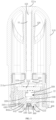
- an electronic atomizing device includes an atomizer 10 and a power supply (not labeled).
- the atomizer 10 is detachably and electrically connected to the power supply.
- the atomizer 10 and the power supply can also be packaged in the same housing, and cannot be detached from each other.
- the power supply can supply power to the atomizer 10.
- the atomizer 10 converts electrical power into heat, so as to atomize liquid in the atomizer 10 to form an aerosol that can be inhaled by the user.
- the liquids can be e-liquid and other aerosol generating substrates.
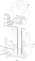
- the atomizer 10 includes a housing 100, a top cover assembly 200, a sealing member 300, a flow guiding member 360, a base 400, an atomizing core 510, and a liquid absorbing member 520.
- components such as the flow guiding member 360 and the base 400 of the atomizer 10 can be omitted as needed, and which are not limited herein.
- the housing 100 includes a shell 110 and a central post 120.
- the central post 120 is connected to the housing 100 and is located in a cavity enclosed by the shell 110.
- the central post 120 is provided with an inhaling hole 121 therein.
- An upper end of the inhaling hole 121 forms a nozzle 121a.
- the nozzle 121a is in a direct fluid communication with an outside atmosphere, thus the user can inhale the aerosol at the nozzle 121a.
- the central post 120 includes a tip portion 123 provided away from the nozzle 121a.
- a cross-sectional size of the tip portion 123 gradually decreases in a direction from top to bottom, such that the tip portion 123 is substantially frustum-shaped.
- the central post 120 has a second inner surface 122 that defines a boundary of the inhaling hole 121.
- the second inner surface 122 is recessed to form a receiving groove 122a.
- the receiving groove 122a extends along a central axis of the inhaling hole 121.
- the top cover assembly 200 is provided in the cavity enclosed by the shell 110.
- the top cover assembly 200 includes a heating top cover 210 and a blocking portion 220.
- the blocking portion 220 is sleeved on the heating top cover 210.
- the blocking portion 220 and the housing 100 cooperatively enclose a liquid reservoir for storing the liquid.
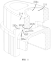
- the heating top cover 210 is provided with an air guiding hole 211 and a guiding passage 212.
- the other portion of the central post 120 abuts against the first inner surface 211a, such that the central post 120 and the air guiding hole 211 are in an interference fit.
- the tip portion 123 of the center post 120 and the first inner surface 211a are spaced apart from each other along a direction perpendicular to a central axis of the air guiding hole 211, such that an annular gap 124 is formed between the tip portion 123 and the first inner surface 211a.
- Two inner sidewall surfaces 213a are provided, which are arranged opposite to each other.
- the inner top wall surface 213b is connected between the two inner sidewall surfaces 213a, such that the two inner sidewall surfaces 213a are both located on the same side (i.e., the lower side) of the inner top wall surface 213b.
- the inner sidewall surface 213a is parallel to the central axis of the inhaling passage 11, and the inner top wall surface 213b is perpendicular to the central axis of the inhaling passage 11. In other words, the inner sidewall surface 213a extends in a vertical direction, and the inner top wall surface 213b extends in a horizontal direction.
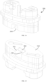
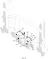
- a part of the inner sidewall surface 213a away from the air guiding hole 211 is recessed in a left-and-right direction to form a first groove 213c, which extends through the outer wall surface 214.
- the heating top cover 210 further has a first inner bottom wall surface 215, which can define a part of a boundary of the first groove 213c.
- the first inner bottom wall surface 215 is connected to a portion of the inner sidewall surface 213a that is not recessed and adjacent to the air guiding hole 211.
- the first inner bottom wall surface 215 is recessed in a front-and-rear direction to form a second groove 215a.
- the first groove 213c and the second groove 215a are in fluid communication with each other, and the extending directions of the two can form a certain angle, for example, 90°.
- the heating top cover 210 further has a second inner bottom wall surface 216.
- the second inner surface 122 defines a part of a boundary of the second groove 215a.
- the second inner bottom wall surface 216 is recessed in the front-and-rear direction to form a micro-groove 216a.
- a width of the micro-groove 216a is less than a width of the second groove 215a.
- An extending direction of the micro-groove 216a forms an angle with the central axis of the inhaling passage 11. For example, referring to FIG.
- the extending direction of the micro-groove 216a and the central axis of the inhaling passage 11 are perpendicular to each other.
- the extending direction of the micro-groove 216a is the horizontal direction.
- the extending direction of the micro-groove 216a can form an acute angle with the central axis of the inhaling passage 11.
- the extending direction of the micro-groove 216a forms a certain inclined angle with the horizontal direction.
- a plurality of micro-grooves 216a may be provided.
- the plurality of micro-grooves 216a are arranged on the second inner bottom wall surface 216 at intervals.
- a part of the inner top wall surface 213b away from the air guiding hole 211 is recessed upward to form a third groove 213d.
- the third groove 213d also extends through the outer wall surface 214.
- the sealing member 300 is connected to the heating top cover 210.
- the sealing member 300, the heating top cover 210, and the shell 110 cooperatively enclose a liquid directing passage 12.
- the liquid directing passage 12 is in fluid communication with the guiding passage 212, and the atomizing core 510 is at least partially located in the liquid directing passage 12.
- the atomizing core 510 is located outside the inhaling passage 11 and the guiding passage 212.
- the atomizing core 510 may include a liquid guiding element and a heating element.
- the liquid guiding element may be a columnar structure made of cotton material.
- the heating element may be made of metal material.
- the heating element is electrically connected to the power supply.
- the heating element can convert the electrical energy into the heat.
- the heating element can be in a spiral shape, and the heating element is spirally wound on the liquid guiding element.
- the liquid guiding element is used to absorb the liquid in the liquid reservoir.
- the heating element is energized, the generated heat can atomize the liquid on the liquid guiding element to form the aerosol.
- the aerosol can be discharged into the liquid directing passage 12.
- the liquid guiding element can be made of porous ceramic, and the heating element is attached to a surface of the porous ceramic.
- the porous ceramic can absorb the liquid in the liquid reservoir through the capillary action of the micropores.
- the heating element is energized, the liquid on the porous ceramic can be atomized to generate the aerosol.
- the base 400 has a fixing surface 420 facing the mounting surface 310.
- the fixing surface 420 defines a part of the boundary of the air guiding cavity 410.
- the base 400 further includes a protruding post 430 located in the air guiding cavity 410.
- a lower end of the protruding post 430 is a fixed end and is fixed to the fixing surface 420.
- An upper end of the protruding post 430 is a free end and protrudes from the fixing surface 420 by a certain height.
- the base 400 is provided with an air inlet channel 440. At least a part of the air inlet channel 440 is located in the boss 430.
- the mounting surface 310 of the sealing member 300 is attached to and abuts against the top surface 431 of the protruding post 430, such that the mounting surface 310 blocks an opening of the output groove 442 on the top surface 431.
- the opening of the output groove 442 on the side surface 432 can form the output port 442a.
- the output groove 442 may only extend through the side surface 432, and the opening of the output groove 442 on the side surface 432 forms the output port 442a. Since the side surface 432 is a vertical surface, the output port 442a is arranged vertically.
- the outside air flows through the air inlet channel 440, the air guiding cavity 410, and the directing hole 340 successively and enters the atomizing cavity 350 to carry the aerosol. Then, the air carrying the aerosol can flow through the guiding passage 212, the air guiding hole 211, and the inhaling hole 121 successively and reaches the nozzle 121a, such that the aerosol is inhaled by the user.
- the dashed arrows in FIG. 4 , FIG. 6 and FIG. 20 indicate the flow trajectory of the air.
- the aerosol remained in the atomizing cavity 350 can be liquefied to form a condensate.
- a seeping liquid can be formed on the atomizing core 510, and the seeping liquid can drop from the atomizing core 510.
- the seeping liquid and the condensate together form the leakage liquid.
- the sealing member 300 includes a boss 330 located in the atomizing cavity 350, and the boss 330 protrudes from the connecting surface 320.
- a part of the leakage liquid can be attached to the connecting surface 320. That is, the leakage liquid can be stored in a recessed space of the atomizing cavity 350 located on the edge of the boss 330.
- the directing hole 340 extends through the free end surface 331 of the boss 330 and is in fluid communication with the atomizing cavity 350, such that the leakage liquid stored in the recessed space is difficult to reach the free end surface 331, thus preventing the leakage liquid from entering the directing hole 340, and ensuring that the recessed space in the atomizing cavity 350 can effectively store the leakage liquid.
- a part of the seeping liquid will drop directly into the directing hole 340, and some aerosol can enter the directing hole 340 from the atomizing cavity 350. This part of the aerosol can also be liquefied in the directing hole 340 to form the condensate.
- a part of the leakage liquid cannot be stored in the recessed space, but can be transferred from the directing hole 340 to the flow guiding member 360 via the input port 341, such that the leakage liquid on the flow guiding member 360 can eventually drop onto the liquid absorbing member 520. Since the flow guiding member 360 is offset from the output port 442a in the horizontal direction, the leakage liquid dropped from the flow guiding member 360 cannot fall into the output port 442a.
- the leakage liquid is prevented from leaking out from the atomizer 10 via the air inlet channel 440 to enter the power supply, thus preventing the leakage liquid from corroding the power supply or even causing the power supply to explode, thereby improving the service life and safety of the power supply.
- the input port 341 is also offset from the output port 442a in the horizontal direction. Even if a part of the leakage liquid cannot enter the flow guiding member 360 and drops directly from the input port 341, it can effectively prevent the leakage liquid dropped from the input port 341 from directly entering the output port 442a, thereby effectively avoiding the leakage liquid from leaking out of the atomizer 10 via the air inlet channel 440.
- the output port 442a can be arranged vertically. Even if the output port 442a is not offset from the input port 341, when the leakage liquid drops from the input port 341, the dropped leakage liquid is difficult to enter the output port 442a.
- the liquid absorbing member 520 Due to the absorption and restraining effect of the liquid absorbing member 520, it can effectively prevent the liquid from flowing freely in the air guiding cavity 410, thereby preventing the liquid level in the recessed space in the air guiding cavity 410 from reaching the output port 442a.
- the condensate and non-liquefied suspended droplets in the atomizing cavity 350 can flow into the guiding passage 212.
- the recessed structures such as the first groove 213c, the second groove 215a, the third groove 213d and the micro-groove 216a
- the recessed structures can obstruct and adsorb the leakage liquid formed by the condensate and suspended droplets, such that the leakage liquid is received in the recessed structures and is difficult to enter the inhaling passage 11, thus preventing the user from inhaling the leakage liquid into the mouth.
- the annular gap 124 is formed between the tip portion 123 of the central post 120 and the first inner surface 211a, even if the leakage liquid enters the air guiding hole 211 from the guiding passage 212, the annular gap 124 can receive and obstruct the leakage liquid, thus preventing the leakage liquid from entering the nozzle 121a to be inhaled by the user. Furthermore, since the receiving groove 122a is formed on the second surface of the center post 120, even if the leakage liquid enters the air inlet 441 via the air guiding hole 211, the receiving groove 122a can receive and obstruct the leakage liquid to prevent the leakage liquid from entering the nozzle 121a to be inhaled by the user. Therefore, due to the triple obstruction of the recessed structures on the inner wall surface 213, the annular gap 124, and the receiving groove 122a, the leakage liquid can be effectively prevented from being inhaled by the user.
- the nozzle 121a faces downward, and the condensate in the atomizing cavity 350 and the seeping liquid dropping from the atomizing core 510 into the atomizing cavity 350 will form the leakage liquid. Under the action of gravity, the leakage liquid will flow from the atomizing cavity 350 into the guiding passage 212. Based on the similar principle, due to the triple obstruction of the recessed structures on the inner wall surface 213, the annular gap 124, and the receiving groove 122a, the leakage liquid can be effectively prevented from flowing out of the atomizer 10 via the nozzle 121a.
- the atomizer 10 can not only effectively prevent the leakage liquid from leaking out of the atomizer 10 via the air inlet channel 440, preventing the leakage liquid from corroding the power supply or causing the power supply to explode, but also can effectively prevent the leakage liquid from leaking out of the atomizer 10 via the nozzle 121a of the air inlet channel 11. If the air inlet channel 440, the air guiding cavity 410, the liquid directing passage 12, the guiding passage 212, and the inhaling passage 11 are regarded as an airflow passage through which the outside air flows, the atomizer 10 can prevent the leakage liquid from leaking out of the atomizer 10 via the upper and lower ends of the airflow passage. In addition, it can prevent the condensate and suspended droplets from being inhaled by the user during inhalation, which can improve the user's inhaling experience.
Landscapes
- Air Humidification (AREA)
- Special Spraying Apparatus (AREA)
- Disinfection, Sterilisation Or Deodorisation Of Air (AREA)
- Devices For Medical Bathing And Washing (AREA)
Claims (9)
- Zerstäuber (10), umfassend:eine obere Abdeckungsanordnung (200), die mit einem Führungsdurchgang (212) und einem Luftleitloch (211) darin versehen ist, wobei die obere Abdeckungsanordnung (200) eine hervorstehende oder vertiefte Struktur zwischen dem Führungsdurchgang (212) und dem Luftleitloch (211) aufweist; undeinen Zerstäubungskern (510), der zumindest teilweise in der oberen Abdeckungsanordnung (200) aufgenommen ist,wobei der Zerstäubungskern (510) konfiguriert ist, um ein Aerosol, das durch Zerstäuben einer Flüssigkeit gebildet wird, über den Führungsdurchgang (212) in das Luftleitloch (211) abzugeben;wobei die obere Abdeckungsanordnung (200) eine Innenwandfläche (213) aufweist, die eine Begrenzung des Führungsdurchgangs (212) definiert, wobei sich die hervorstehende oder vertiefte Struktur an der Innenwandfläche (213) befindet.
- Zerstäuber (10) nach Anspruch 1, wobei die obere Abdeckungsanordnung (200) ferner eine äußere Wandfläche (214) aufweist, die mit der inneren Wandfläche (213) verbunden ist, sich der Führungsdurchgang (212) durch die äußere Wandfläche (214) erstreckt, die innere Wandfläche (213) eine innere Seitenwandfläche (213a) parallel zu einer Mittelachse des Zerstäubers (10) umfasst, die vertiefte Struktur eine erste Nut (213c) umfasst, die an der inneren Seitenwandfläche (213a) gebildet ist und sich durch die äußere Wandfläche (214) erstreckt.
- Zerstäuber (10) nach Anspruch 2, wobei die vertiefte Struktur ferner eine zweite Nut (215a) in Fluidverbindung mit der ersten Nut (213c) umfasst, wobei eine Erstreckungsrichtung der zweiten Nut (215a) einen Winkel mit einer Erstreckungsrichtung der ersten Nut (213c) bildet.
- Zerstäuber (10) nach Anspruch 3, wobei die obere Abdeckungsanordnung (200) ferner eine zweite innere Bodenwandfläche (216) aufweist, die einen Teil einer Begrenzung der zweiten Nut (215a) definiert, wobei die vertiefte Struktur ferner eine Mikronut (216a) umfasst, die an der zweiten inneren Bodenwandfläche (216) gebildet ist, wobei eine Breite der Mikronut (216a) geringer ist als eine Breite der zweiten Nut (215a), wobei eine Erstreckungsrichtung der Mikronut (216a) einen Winkel mit der Mittelachse des Zerstäubers (10) bildet.
- Zerstäuber (10) nach Anspruch 2, wobei die innere Wandfläche (213) eine innere obere Wandfläche (213b) umfasst, die innere obere Wandfläche (213b) einen Winkel mit der Mittelachse des Zerstäubers (10) bildet und mit der inneren Seitenwandfläche (213a) verbunden ist, die vertiefte Struktur ferner eine dritte Nut (213d) umfasst, die an der inneren oberen Wandfläche (213b) gebildet ist und sich durch die äußere Wandfläche (214) erstreckt.
- Zerstäuber (10) nach Anspruch 1, ferner umfassend ein Gehäuse (100), wobei die obere Abdeckungsanordnung (200) und der Zerstäubungskern (510) zumindest teilweise in dem Gehäuse (100) aufgenommen sind, das Gehäuse (100) mit einem Inhalationsloch (121) versehen ist, das koaxial zu dem Luftleitloch (211) verläuft, das Luftleitloch (211) in Fluidverbindung zwischen dem Inhalationsloch (121) und dem Führungsdurchgang (212) ist, ein Ende des Inhalationslochs (121), das von dem Luftleitloch (211) entfernt ist, eine Düse (121a) bildet, die in Fluidverbindung mit einer äußeren Atmosphäre ist.
- Zerstäuber (10) nach Anspruch 6, wobei das Gehäuse (100) eine Schale (110) und einen mittleren Ständer (120) umfasst, wobei der mittlere Ständer (120) in der Schale (110) angeordnet und in das Luftleitloch (211) eingesetzt ist, der mittlere Ständer (120) einen Spitzenabschnitt (123) umfasst, der sich in dem Luftleitloch (211) befindet, die obere Abdeckungsanordnung (200) ferner eine erste Innenfläche (211a) aufweist, die eine Begrenzung des Luftleitlochs (211) definiert, und ein Spalt (124) zwischen dem Spitzenabschnitt (123) und der ersten Innenfläche (211a) gebildet ist.
- Zerstäuber (10) nach Anspruch 7, wobei der mittlere Ständer (120) eine zweite Innenfläche (122) aufweist, die eine Begrenzung des Inhalationslochs (121) definiert, wobei die zweite Innenfläche (122) vertieft ist, um eine Aufnahmenut (122a) zu bilden, die sich entlang einer Mittelachse des Inhalationslochs (121) erstreckt.
- Elektronische Zerstäubungsvorrichtung, umfassend eine Stromversorgung und den Zerstäuber (10) nach einem der vorherigen Ansprüche, der elektrisch mit der Stromversorgung verbunden ist.
Applications Claiming Priority (1)
| Application Number | Priority Date | Filing Date | Title |
|---|---|---|---|
| CN202023302851.1U CN214710376U (zh) | 2020-12-30 | 2020-12-30 | 雾化器及电子雾化装置 |
Publications (2)
| Publication Number | Publication Date |
|---|---|
| EP4029388A1 EP4029388A1 (de) | 2022-07-20 |
| EP4029388B1 true EP4029388B1 (de) | 2024-10-09 |
Family
ID=78636384
Family Applications (1)
| Application Number | Title | Priority Date | Filing Date |
|---|---|---|---|
| EP21217925.3A Active EP4029388B1 (de) | 2020-12-30 | 2021-12-28 | Zerstäuber und elektronische zerstäubungsvorrichtungen damit |
Country Status (3)
| Country | Link |
|---|---|
| US (1) | US20220202086A1 (de) |
| EP (1) | EP4029388B1 (de) |
| CN (1) | CN214710376U (de) |
Families Citing this family (9)
| Publication number | Priority date | Publication date | Assignee | Title |
|---|---|---|---|---|
| KR102353864B1 (ko) * | 2019-04-23 | 2022-01-20 | 주식회사 케이티앤지 | 카트리지 및 이를 포함하는 에어로졸 생성 장치 |
| CN110447960A (zh) * | 2019-05-24 | 2019-11-15 | 东莞市阿尔法电子科技有限公司 | 封闭件及电子雾化器 |
| CA212411S (en) * | 2021-11-03 | 2024-03-04 | Shenzhen Relx Tech Co Ltd | Conductive Pin of a Pod for an Electronic Cigarette |
| CN116406835A (zh) * | 2021-12-30 | 2023-07-11 | 深圳麦克韦尔科技有限公司 | 一种电子雾化装置及其雾化器 |
| WO2023123165A1 (zh) * | 2021-12-30 | 2023-07-06 | 深圳麦克韦尔科技有限公司 | 电子雾化装置及其雾化器 |
| WO2023123244A1 (zh) * | 2021-12-30 | 2023-07-06 | 深圳麦克韦尔科技有限公司 | 一种电子雾化装置及其雾化器 |
| WO2024065747A1 (zh) * | 2022-09-30 | 2024-04-04 | 深圳市卓力能技术有限公司 | 一种雾化芯及雾化器 |
| JPWO2024084568A1 (de) * | 2022-10-18 | 2024-04-25 | ||
| CN116965603B (zh) * | 2023-09-13 | 2026-05-12 | 宁波恩瓦科技有限公司 | 雾化模块、气雾弹和雾化模块的制造方法 |
Citations (5)
| Publication number | Priority date | Publication date | Assignee | Title |
|---|---|---|---|---|
| WO2016154994A1 (zh) | 2015-04-02 | 2016-10-06 | 惠州市吉瑞科技有限公司 | 雾化组件和电子烟 |
| CN109393570A (zh) | 2018-11-12 | 2019-03-01 | 安克创新科技股份有限公司 | 雾化装置及电子烟 |
| WO2020048513A1 (zh) | 2018-09-05 | 2020-03-12 | 深圳麦克韦尔科技有限公司 | 雾化装置及电子雾化设备 |
| CN111165879A (zh) | 2019-11-19 | 2020-05-19 | 深圳雾芯科技有限公司 | 一种雾化装置 |
| CN211910515U (zh) | 2019-12-17 | 2020-11-13 | 深圳市合元科技有限公司 | 雾化器及电子烟 |
-
2020
- 2020-12-30 CN CN202023302851.1U patent/CN214710376U/zh active Active
-
2021
- 2021-12-27 US US17/562,484 patent/US20220202086A1/en not_active Abandoned
- 2021-12-28 EP EP21217925.3A patent/EP4029388B1/de active Active
Patent Citations (5)
| Publication number | Priority date | Publication date | Assignee | Title |
|---|---|---|---|---|
| WO2016154994A1 (zh) | 2015-04-02 | 2016-10-06 | 惠州市吉瑞科技有限公司 | 雾化组件和电子烟 |
| WO2020048513A1 (zh) | 2018-09-05 | 2020-03-12 | 深圳麦克韦尔科技有限公司 | 雾化装置及电子雾化设备 |
| CN109393570A (zh) | 2018-11-12 | 2019-03-01 | 安克创新科技股份有限公司 | 雾化装置及电子烟 |
| CN111165879A (zh) | 2019-11-19 | 2020-05-19 | 深圳雾芯科技有限公司 | 一种雾化装置 |
| CN211910515U (zh) | 2019-12-17 | 2020-11-13 | 深圳市合元科技有限公司 | 雾化器及电子烟 |
Also Published As
| Publication number | Publication date |
|---|---|
| CN214710376U (zh) | 2021-11-16 |
| US20220202086A1 (en) | 2022-06-30 |
| EP4029388A1 (de) | 2022-07-20 |
Similar Documents
| Publication | Publication Date | Title |
|---|---|---|
| EP4029388A1 (de) | Zerstäuber und elektronische zerstäubungsvorrichtungen damit | |
| US20250288012A1 (en) | Atomizer and electronic atomizing device having the same | |
| US12419355B2 (en) | Atomizer and electronic atomizing device | |
| CN113892696A (zh) | 雾化器及电子雾化装置 | |
| US11925206B2 (en) | Electronic cigarette having dual air passages | |
| ES2837011T3 (es) | Tanque de almacenamiento de líquido para un sistema de suministro de vapor | |
| CN114158774B (zh) | 电子雾化装置及雾化器 | |
| CN112004603B (zh) | 微流体料盒和包括该微流体料盒的微流体递送装置 | |
| EP4194037B1 (de) | Zerstäuber und elektronische zerstäubungsvorrichtung | |
| EP3360430A2 (de) | Elektronische zigarette und zerstäuber dafür | |
| CN218650266U (zh) | 雾化器及电子雾化装置 | |
| CN114158773A (zh) | 电子雾化装置及雾化器 | |
| WO2023124213A1 (zh) | 一种雾化器及电子雾化装置 | |
| CN215347036U (zh) | 一种雾化器和气溶胶生成装置 | |
| CN215013581U (zh) | 雾化器及电子雾化装置 | |
| CN218245693U (zh) | 一种雾化器及电子雾化装置 | |
| CN217407797U (zh) | 雾化器和雾化装置 | |
| CN218898354U (zh) | 雾化芯及气溶胶生成装置 | |
| CN218650319U (zh) | 雾化芯及气溶胶生成装置 | |
| JP7482973B2 (ja) | 霧化部品及び電子霧化装置 | |
| CN218185262U (zh) | 雾化组件及气雾发生装置 | |
| CN222031473U (zh) | 吸嘴及雾化装置 | |
| CN220343652U (zh) | 一种雾化器及气溶胶生成装置 | |
| CN219939720U (zh) | 雾化组件及电子雾化装置 | |
| CN222054579U (zh) | 雾化器和雾化装置 |
Legal Events
| Date | Code | Title | Description |
|---|---|---|---|
| PUAI | Public reference made under article 153(3) epc to a published international application that has entered the european phase |
Free format text: ORIGINAL CODE: 0009012 |
|
| STAA | Information on the status of an ep patent application or granted ep patent |
Free format text: STATUS: THE APPLICATION HAS BEEN PUBLISHED |
|
| AK | Designated contracting states |
Kind code of ref document: A1 Designated state(s): AL AT BE BG CH CY CZ DE DK EE ES FI FR GB GR HR HU IE IS IT LI LT LU LV MC MK MT NL NO PL PT RO RS SE SI SK SM TR |
|
| STAA | Information on the status of an ep patent application or granted ep patent |
Free format text: STATUS: REQUEST FOR EXAMINATION WAS MADE |
|
| 17P | Request for examination filed |
Effective date: 20230117 |
|
| RBV | Designated contracting states (corrected) |
Designated state(s): AL AT BE BG CH CY CZ DE DK EE ES FI FR GB GR HR HU IE IS IT LI LT LU LV MC MK MT NL NO PL PT RO RS SE SI SK SM TR |
|
| GRAP | Despatch of communication of intention to grant a patent |
Free format text: ORIGINAL CODE: EPIDOSNIGR1 |
|
| STAA | Information on the status of an ep patent application or granted ep patent |
Free format text: STATUS: GRANT OF PATENT IS INTENDED |
|
| RIC1 | Information provided on ipc code assigned before grant |
Ipc: A24F 40/40 20200101AFI20240422BHEP |
|
| INTG | Intention to grant announced |
Effective date: 20240517 |
|
| GRAS | Grant fee paid |
Free format text: ORIGINAL CODE: EPIDOSNIGR3 |
|
| GRAA | (expected) grant |
Free format text: ORIGINAL CODE: 0009210 |
|
| STAA | Information on the status of an ep patent application or granted ep patent |
Free format text: STATUS: THE PATENT HAS BEEN GRANTED |
|
| P01 | Opt-out of the competence of the unified patent court (upc) registered |
Free format text: CASE NUMBER: APP_48977/2024 Effective date: 20240828 |
|
| AK | Designated contracting states |
Kind code of ref document: B1 Designated state(s): AL AT BE BG CH CY CZ DE DK EE ES FI FR GB GR HR HU IE IS IT LI LT LU LV MC MK MT NL NO PL PT RO RS SE SI SK SM TR |
|
| REG | Reference to a national code |
Ref country code: CH Ref legal event code: EP |
|
| REG | Reference to a national code |
Ref country code: DE Ref legal event code: R096 Ref document number: 602021019903 Country of ref document: DE |
|
| REG | Reference to a national code |
Ref country code: IE Ref legal event code: FG4D |
|
| REG | Reference to a national code |
Ref country code: LT Ref legal event code: MG9D |
|
| REG | Reference to a national code |
Ref country code: NL Ref legal event code: MP Effective date: 20241009 |
|
| REG | Reference to a national code |
Ref country code: AT Ref legal event code: MK05 Ref document number: 1729551 Country of ref document: AT Kind code of ref document: T Effective date: 20241009 |
|
| PG25 | Lapsed in a contracting state [announced via postgrant information from national office to epo] |
Ref country code: NL Free format text: LAPSE BECAUSE OF FAILURE TO SUBMIT A TRANSLATION OF THE DESCRIPTION OR TO PAY THE FEE WITHIN THE PRESCRIBED TIME-LIMIT Effective date: 20241009 |
|
| PG25 | Lapsed in a contracting state [announced via postgrant information from national office to epo] |
Ref country code: NL Free format text: LAPSE BECAUSE OF FAILURE TO SUBMIT A TRANSLATION OF THE DESCRIPTION OR TO PAY THE FEE WITHIN THE PRESCRIBED TIME-LIMIT Effective date: 20241009 |
|
| PG25 | Lapsed in a contracting state [announced via postgrant information from national office to epo] |
Ref country code: IS Free format text: LAPSE BECAUSE OF FAILURE TO SUBMIT A TRANSLATION OF THE DESCRIPTION OR TO PAY THE FEE WITHIN THE PRESCRIBED TIME-LIMIT Effective date: 20250209 Ref country code: HR Free format text: LAPSE BECAUSE OF FAILURE TO SUBMIT A TRANSLATION OF THE DESCRIPTION OR TO PAY THE FEE WITHIN THE PRESCRIBED TIME-LIMIT Effective date: 20241009 Ref country code: PT Free format text: LAPSE BECAUSE OF FAILURE TO SUBMIT A TRANSLATION OF THE DESCRIPTION OR TO PAY THE FEE WITHIN THE PRESCRIBED TIME-LIMIT Effective date: 20250210 |
|
| PG25 | Lapsed in a contracting state [announced via postgrant information from national office to epo] |
Ref country code: FI Free format text: LAPSE BECAUSE OF FAILURE TO SUBMIT A TRANSLATION OF THE DESCRIPTION OR TO PAY THE FEE WITHIN THE PRESCRIBED TIME-LIMIT Effective date: 20241009 |
|
| PG25 | Lapsed in a contracting state [announced via postgrant information from national office to epo] |
Ref country code: BG Free format text: LAPSE BECAUSE OF FAILURE TO SUBMIT A TRANSLATION OF THE DESCRIPTION OR TO PAY THE FEE WITHIN THE PRESCRIBED TIME-LIMIT Effective date: 20241009 |
|
| PG25 | Lapsed in a contracting state [announced via postgrant information from national office to epo] |
Ref country code: ES Free format text: LAPSE BECAUSE OF FAILURE TO SUBMIT A TRANSLATION OF THE DESCRIPTION OR TO PAY THE FEE WITHIN THE PRESCRIBED TIME-LIMIT Effective date: 20241009 |
|
| PG25 | Lapsed in a contracting state [announced via postgrant information from national office to epo] |
Ref country code: NO Free format text: LAPSE BECAUSE OF FAILURE TO SUBMIT A TRANSLATION OF THE DESCRIPTION OR TO PAY THE FEE WITHIN THE PRESCRIBED TIME-LIMIT Effective date: 20250109 |
|
| PG25 | Lapsed in a contracting state [announced via postgrant information from national office to epo] |
Ref country code: LV Free format text: LAPSE BECAUSE OF FAILURE TO SUBMIT A TRANSLATION OF THE DESCRIPTION OR TO PAY THE FEE WITHIN THE PRESCRIBED TIME-LIMIT Effective date: 20241009 Ref country code: GR Free format text: LAPSE BECAUSE OF FAILURE TO SUBMIT A TRANSLATION OF THE DESCRIPTION OR TO PAY THE FEE WITHIN THE PRESCRIBED TIME-LIMIT Effective date: 20250110 Ref country code: AT Free format text: LAPSE BECAUSE OF FAILURE TO SUBMIT A TRANSLATION OF THE DESCRIPTION OR TO PAY THE FEE WITHIN THE PRESCRIBED TIME-LIMIT Effective date: 20241009 |
|
| PG25 | Lapsed in a contracting state [announced via postgrant information from national office to epo] |
Ref country code: PL Free format text: LAPSE BECAUSE OF FAILURE TO SUBMIT A TRANSLATION OF THE DESCRIPTION OR TO PAY THE FEE WITHIN THE PRESCRIBED TIME-LIMIT Effective date: 20241009 |
|
| PG25 | Lapsed in a contracting state [announced via postgrant information from national office to epo] |
Ref country code: RS Free format text: LAPSE BECAUSE OF FAILURE TO SUBMIT A TRANSLATION OF THE DESCRIPTION OR TO PAY THE FEE WITHIN THE PRESCRIBED TIME-LIMIT Effective date: 20250109 |
|
| REG | Reference to a national code |
Ref country code: DE Ref legal event code: R026 Ref document number: 602021019903 Country of ref document: DE |
|
| PG25 | Lapsed in a contracting state [announced via postgrant information from national office to epo] |
Ref country code: SM Free format text: LAPSE BECAUSE OF FAILURE TO SUBMIT A TRANSLATION OF THE DESCRIPTION OR TO PAY THE FEE WITHIN THE PRESCRIBED TIME-LIMIT Effective date: 20241009 |
|
| PG25 | Lapsed in a contracting state [announced via postgrant information from national office to epo] |
Ref country code: MC Free format text: LAPSE BECAUSE OF FAILURE TO SUBMIT A TRANSLATION OF THE DESCRIPTION OR TO PAY THE FEE WITHIN THE PRESCRIBED TIME-LIMIT Effective date: 20241009 |
|
| PG25 | Lapsed in a contracting state [announced via postgrant information from national office to epo] |
Ref country code: DK Free format text: LAPSE BECAUSE OF FAILURE TO SUBMIT A TRANSLATION OF THE DESCRIPTION OR TO PAY THE FEE WITHIN THE PRESCRIBED TIME-LIMIT Effective date: 20241009 |
|
| PLBI | Opposition filed |
Free format text: ORIGINAL CODE: 0009260 |
|
| PG25 | Lapsed in a contracting state [announced via postgrant information from national office to epo] |
Ref country code: EE Free format text: LAPSE BECAUSE OF FAILURE TO SUBMIT A TRANSLATION OF THE DESCRIPTION OR TO PAY THE FEE WITHIN THE PRESCRIBED TIME-LIMIT Effective date: 20241009 |
|
| PLAX | Notice of opposition and request to file observation + time limit sent |
Free format text: ORIGINAL CODE: EPIDOSNOBS2 |
|
| PG25 | Lapsed in a contracting state [announced via postgrant information from national office to epo] |
Ref country code: RO Free format text: LAPSE BECAUSE OF FAILURE TO SUBMIT A TRANSLATION OF THE DESCRIPTION OR TO PAY THE FEE WITHIN THE PRESCRIBED TIME-LIMIT Effective date: 20241009 |
|
| PG25 | Lapsed in a contracting state [announced via postgrant information from national office to epo] |
Ref country code: SK Free format text: LAPSE BECAUSE OF FAILURE TO SUBMIT A TRANSLATION OF THE DESCRIPTION OR TO PAY THE FEE WITHIN THE PRESCRIBED TIME-LIMIT Effective date: 20241009 |
|
| PG25 | Lapsed in a contracting state [announced via postgrant information from national office to epo] |
Ref country code: CZ Free format text: LAPSE BECAUSE OF FAILURE TO SUBMIT A TRANSLATION OF THE DESCRIPTION OR TO PAY THE FEE WITHIN THE PRESCRIBED TIME-LIMIT Effective date: 20241009 |
|
| PG25 | Lapsed in a contracting state [announced via postgrant information from national office to epo] |
Ref country code: IT Free format text: LAPSE BECAUSE OF FAILURE TO SUBMIT A TRANSLATION OF THE DESCRIPTION OR TO PAY THE FEE WITHIN THE PRESCRIBED TIME-LIMIT Effective date: 20241009 |
|
| REG | Reference to a national code |
Ref country code: CH Ref legal event code: PL |
|
| 26 | Opposition filed |
Opponent name: PHILIP MORRIS PRODUCTS S.A. Effective date: 20250702 |
|
| PG25 | Lapsed in a contracting state [announced via postgrant information from national office to epo] |
Ref country code: LU Free format text: LAPSE BECAUSE OF NON-PAYMENT OF DUE FEES Effective date: 20241228 |
|
| PG25 | Lapsed in a contracting state [announced via postgrant information from national office to epo] |
Ref country code: SE Free format text: LAPSE BECAUSE OF FAILURE TO SUBMIT A TRANSLATION OF THE DESCRIPTION OR TO PAY THE FEE WITHIN THE PRESCRIBED TIME-LIMIT Effective date: 20241009 |
|
| REG | Reference to a national code |
Ref country code: BE Ref legal event code: MM Effective date: 20241231 |
|
| PG25 | Lapsed in a contracting state [announced via postgrant information from national office to epo] |
Ref country code: BE Free format text: LAPSE BECAUSE OF NON-PAYMENT OF DUE FEES Effective date: 20241231 |
|
| PG25 | Lapsed in a contracting state [announced via postgrant information from national office to epo] |
Ref country code: CH Free format text: LAPSE BECAUSE OF NON-PAYMENT OF DUE FEES Effective date: 20241231 |
|
| PG25 | Lapsed in a contracting state [announced via postgrant information from national office to epo] |
Ref country code: IE Free format text: LAPSE BECAUSE OF NON-PAYMENT OF DUE FEES Effective date: 20241228 |
|
| PLBB | Reply of patent proprietor to notice(s) of opposition received |
Free format text: ORIGINAL CODE: EPIDOSNOBS3 |
|
| PGFP | Annual fee paid to national office [announced via postgrant information from national office to epo] |
Ref country code: GB Payment date: 20251229 Year of fee payment: 5 |
|
| PGFP | Annual fee paid to national office [announced via postgrant information from national office to epo] |
Ref country code: FR Payment date: 20251230 Year of fee payment: 5 |
|
| PGFP | Annual fee paid to national office [announced via postgrant information from national office to epo] |
Ref country code: DE Payment date: 20251231 Year of fee payment: 5 |