EP4029226B1 - Verriegelungsanordnung für ein klappbares elektronisches gerät - Google Patents
Verriegelungsanordnung für ein klappbares elektronisches gerät Download PDFInfo
- Publication number
- EP4029226B1 EP4029226B1 EP19791235.5A EP19791235A EP4029226B1 EP 4029226 B1 EP4029226 B1 EP 4029226B1 EP 19791235 A EP19791235 A EP 19791235A EP 4029226 B1 EP4029226 B1 EP 4029226B1
- Authority
- EP
- European Patent Office
- Prior art keywords
- hinge assembly
- frame section
- rotation shaft
- hinge
- axis
- Prior art date
- Legal status (The legal status is an assumption and is not a legal conclusion. Google has not performed a legal analysis and makes no representation as to the accuracy of the status listed.)
- Active
Links
Images


Classifications
-
- H—ELECTRICITY
- H04—ELECTRIC COMMUNICATION TECHNIQUE
- H04M—TELEPHONIC COMMUNICATION
- H04M1/00—Substation equipment, e.g. for use by subscribers
- H04M1/02—Constructional features of telephone sets
- H04M1/0202—Portable telephone sets, e.g. cordless phones, mobile phones or bar type handsets
- H04M1/0206—Portable telephones comprising a plurality of mechanically joined movable body parts, e.g. hinged housings
- H04M1/0208—Portable telephones comprising a plurality of mechanically joined movable body parts, e.g. hinged housings characterized by the relative motions of the body parts
- H04M1/0214—Foldable telephones, i.e. with body parts pivoting to an open position around an axis parallel to the plane they define in closed position
- H04M1/0216—Foldable in one direction, i.e. using a one degree of freedom hinge
-
- G—PHYSICS
- G06—COMPUTING OR CALCULATING; COUNTING
- G06F—ELECTRIC DIGITAL DATA PROCESSING
- G06F1/00—Details not covered by groups G06F3/00 - G06F13/00 and G06F21/00
- G06F1/16—Constructional details or arrangements
- G06F1/1613—Constructional details or arrangements for portable computers
- G06F1/1615—Constructional details or arrangements for portable computers with several enclosures having relative motions, each enclosure supporting at least one I/O or computing function
- G06F1/1616—Constructional details or arrangements for portable computers with several enclosures having relative motions, each enclosure supporting at least one I/O or computing function with folding flat displays, e.g. laptop computers or notebooks having a clamshell configuration, with body parts pivoting to an open position around an axis parallel to the plane they define in closed position
-
- G—PHYSICS
- G06—COMPUTING OR CALCULATING; COUNTING
- G06F—ELECTRIC DIGITAL DATA PROCESSING
- G06F1/00—Details not covered by groups G06F3/00 - G06F13/00 and G06F21/00
- G06F1/16—Constructional details or arrangements
- G06F1/1613—Constructional details or arrangements for portable computers
- G06F1/1633—Constructional details or arrangements of portable computers not specific to the type of enclosures covered by groups G06F1/1615 - G06F1/1626
- G06F1/1675—Miscellaneous details related to the relative movement between the different enclosures or enclosure parts
- G06F1/1679—Miscellaneous details related to the relative movement between the different enclosures or enclosure parts for locking or maintaining the movable parts of the enclosure in a fixed position, e.g. latching mechanism at the edge of the display in a laptop or for the screen protective cover of a PDA
-
- G—PHYSICS
- G06—COMPUTING OR CALCULATING; COUNTING
- G06F—ELECTRIC DIGITAL DATA PROCESSING
- G06F1/00—Details not covered by groups G06F3/00 - G06F13/00 and G06F21/00
- G06F1/16—Constructional details or arrangements
- G06F1/1613—Constructional details or arrangements for portable computers
- G06F1/1633—Constructional details or arrangements of portable computers not specific to the type of enclosures covered by groups G06F1/1615 - G06F1/1626
- G06F1/1675—Miscellaneous details related to the relative movement between the different enclosures or enclosure parts
- G06F1/1681—Details related solely to hinges
-
- G—PHYSICS
- G06—COMPUTING OR CALCULATING; COUNTING
- G06F—ELECTRIC DIGITAL DATA PROCESSING
- G06F2203/00—Indexing scheme relating to G06F3/00 - G06F3/048
- G06F2203/041—Indexing scheme relating to G06F3/041 - G06F3/045
- G06F2203/04102—Flexible digitiser, i.e. constructional details for allowing the whole digitising part of a device to be flexed or rolled like a sheet of paper
-
- H—ELECTRICITY
- H04—ELECTRIC COMMUNICATION TECHNIQUE
- H04M—TELEPHONIC COMMUNICATION
- H04M1/00—Substation equipment, e.g. for use by subscribers
- H04M1/02—Constructional features of telephone sets
- H04M1/0202—Portable telephone sets, e.g. cordless phones, mobile phones or bar type handsets
- H04M1/0206—Portable telephones comprising a plurality of mechanically joined movable body parts, e.g. hinged housings
- H04M1/0208—Portable telephones comprising a plurality of mechanically joined movable body parts, e.g. hinged housings characterized by the relative motions of the body parts
- H04M1/0214—Foldable telephones, i.e. with body parts pivoting to an open position around an axis parallel to the plane they define in closed position
- H04M1/0216—Foldable in one direction, i.e. using a one degree of freedom hinge
- H04M1/022—The hinge comprising two parallel pivoting axes
-
- H—ELECTRICITY
- H04—ELECTRIC COMMUNICATION TECHNIQUE
- H04M—TELEPHONIC COMMUNICATION
- H04M1/00—Substation equipment, e.g. for use by subscribers
- H04M1/02—Constructional features of telephone sets
- H04M1/0202—Portable telephone sets, e.g. cordless phones, mobile phones or bar type handsets
- H04M1/026—Details of the structure or mounting of specific components
- H04M1/0266—Details of the structure or mounting of specific components for a display module assembly
- H04M1/0268—Details of the structure or mounting of specific components for a display module assembly including a flexible display panel
Definitions
- the disclosure relates to a hinge assembly for an electronic device, the hinge assembly being moveable between an unfolded position and a folded end position.
- the size of electronic devices is an important consideration when designing electronic devices.
- the user oftentimes requests the outer dimensions of the device to be as small as possible while still providing a display which is as large as possible.
- This problem may be solved, e.g., by means of a foldable electronic device comprising one or several support bodies, e.g. interconnected by means of hinges, covered by a display.
- the support body/bodies and the display can be folded together to provide an as small electronic device as possible, and unfolded to provide an as large display as possible.
- the hinge can be locked in both an unfolded position and a folded position.
- stacking up of manufacturing tolerances for any locking components affects the flatness of the electronic device in the unfolded position, and movement between several pivot points have to be synchronized in order to provide enough locking force.
- US 10209743B1 provides a flexible display device including a base support of structurally flexible, a flexible display which is supported by and bendable with the base support, and at least one positioning mechanism disposed leftward or rightward of the base support.
- WO03044974A1 provides a hinge device including a housing, a cam, a cam follower to interact with the cam, and a resilient member.
- the housing contains the cam, cam follower and resilient member. The cam moves linearly, and the cam follower rotates.
- a hinge assembly for an electronic device, the hinge assembly being moveable between an unfolded position and a folded end position, the hinge assembly comprising a row of interconnected and abutting hinge blades and at least one linear actuator, the hinge blades being aligned in a common plane when the hinge assembly is in the unfolded position, each hinge blade being rotated relative neighboring hinge blades around a hinge assembly rotation axis when the hinge assembly is moved to the folded end position, the linear actuator comprising a rotation shaft and a linear drive arrangement, a first end of the linear drive arrangement being interconnected with the rotation shaft, a second, opposite end of the linear drive arrangement being connected to at least one hinge blade, an actuator axis extending between the first and second ends and perpendicular to the hinge assembly rotation axis, the linear actuator further comprising a locking arrangement for locking the hinge assembly in at least one of the unfolded position and the folded end position, the locking arrangement comprising a cam element interlocking with a cam section located on the rotation shaft
- This solution allows the sections of the electronic device, which are interconnected by the hinge assembly, to be pivoted easily without effort, while still being securely locked into place in one of the desired positions, i.e. in the unfolded position or a folded end position. Furthermore, by having only one locking arrangement, there is no stacking up of individual manufacturing tolerances, providing better flatness in the unfolded position, while avoiding having to synchronize movement between several pivot points in order to provide enough locking force.
- the rotation shaft extends in parallel with the hinge assembly rotation axis and the linear drive arrangement extends along the actuator axis, the cam element enclosing a section of the rotation shaft such that the cam element and the rotation shaft share a center axis, providing a reliable locking arrangement which nevertheless takes up very little space.
- the rotation shaft extends perpendicular to the hinge assembly rotation axis and the actuator axis, the cam element being arranged adjacent one end of the rotation shaft, the cam element comprising a circular element extending in a first plane perpendicular to a center axis of the rotation shaft, a center axis of the cam element extending in parallel with said center axis of the rotation shaft, the cam section comprising a circular section extending in the first plane and comprising at least one peripheral notch adapted for receiving the circular element.
- the hinge assembly further comprises a resilient element biasing the cam element towards the cam section.
- the resilient element comprises a spring.
- the hinge assembly comprises a neutral axis, a center axis of the rotation shaft intersecting the neutral axis, a first end of the linear drive arrangement engaging the rotation shaft, a second end of the linear drive arrangement engaging a first location and a second location of an individual hinge blade, the first location and the second location being located on opposite sides of, and with equidistant spacing from, the neutral axis.
- the linear drive arrangement comprises a loop, a first loop section and a second loop section extending on opposite sides of, and with equidistant spacing from, the neutral axis, a first rotation of the rotation shaft rotating the loop in a first direction, and a second rotation of the rotation shaft rotating the loop in a second direction, providing a secure, simple, and reliable linear actuation.
- the linear drive arrangement comprises a chain or a wire.
- the wire is partially wound around the rotation shaft.
- a first dimension of a first outer surface of the hinge assembly is larger than a corresponding second dimension of a second outer surface of the hinge assembly when the hinge assembly is in the folded end position, the linear actuator being actuated by a difference between the first dimension and the second dimension.
- an electronic device comprising a first frame section, a second frame section, a display connected to at least one of the first frame section and the second frame section, and a hinge assembly according to the above interconnecting the first frame section and the second frame section such that the first frame section and the second frame section are pivotable, relative each other, between an unfolded position and a first folded end position, the first frame section and the second frame section being aligned and releasably locked in a common plane when in the unfolded position, the second frame section being superimposed on the first frame section and releasably locked when in the first folded end position.
- the hinge assembly interconnects the first frame section and the second frame section such that the first frame section and the second frame section are pivotable, relative each other, between an unfolded position and a second folded end position, the first frame section being superimposed on the second frame section and releasably locked when in the second folded end position.
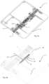
- Figs. 8 and 9 show an electronic device 17 comprising a first frame section 4, a second frame section 5, a display 2 connected to at least one of the first frame section 4 and the second frame section 5, and a hinge assembly 1 interconnecting the first frame section 4 and the second frame section 5 such that the first frame section 4 and the second frame section 5 are pivotable, relative each other, between an unfolded position P1 and a first folded end position P2a.
- the hinge assembly 1 is also moveable between the unfolded position P1 and a second folded end position P2b. As the hinge assembly 1 is folded, the electronic device 17 is also folded from an unfolded position to a folded end position.
- the electronic device 17 may also comprise a back cover arranged oppositely to the display 2.
- the first frame section 4 and the second frame section 5 are aligned and releasably locked in a common plane when in the unfolded position P1, and the second frame section 5 is superimposed on the first frame section 4 and releasably locked when in the first folded end position P2a.
- the first frame section 4 is superimposed on the second frame section 5 and releasably locked when in the second folded end position P2b.
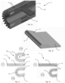
- the hinge assembly 1 comprises a row of interconnected and abutting hinge blades 9, as shown in Figs. 1a to 1d , and at least one linear actuator 7.
- the hinge blades 9 may be tapered and interconnected by means of an elongated connection element extending along an actuator axis A2, as shown in Fig. 2b .
- the hinge blades 9 may be tapered in one direction, as shown in Fig. 1d , or in two directions, as shown in Fig. 1c .
- One-directional tapering allows the hinge assembly 1 to fold in only one direction, e.g. to first folded end position P2a, while bi-directional tapering allows the hinge assembly 1 to fold in two directions, i.e. to first folded end position P2a as well as second folded end position P2b.
- the hinge blades 9 are aligned in a common plane when the hinge assembly 1 is in the unfolded position P1, as shown in the middle drawings of Figs. 1c and 1d .
- Each hinge blade 9 is rotated relative neighboring hinge blades 9 around a hinge assembly rotation axis A1 when the hinge assembly 1 is moved to one of the folded end positions P2a, P2b, as shown in the lowermost drawings of Figs. 1c and 1d , as well as in the uppermost drawing of Fig. 1c .
- the linear actuator 7 comprises a rotation shaft 12, extending within the second frame section 5, and at least one linear drive arrangement 13.
- the first end of the linear drive arrangement 13 is interconnected with the rotation shaft 12, and the second, opposite end of the linear drive arrangement 13 is connected to at least one hinge blade 9 or to the first frame section 4.
- the actuator axis A2 extends between the first end and the second end, and perpendicular to the hinge assembly rotation axis A1. Actuation of the linear actuator 7 along the actuator axis A2 urges each hinge blade 9 to rotate relative neighboring hinge blades 9 around the hinge assembly rotation axis A1.
- a first dimension of a first outer surface 8a of the hinge assembly 1 may be larger than a corresponding second dimension of a second outer surface 8b of the hinge assembly 1 when the hinge assembly 1 is in the first folded end position P2a, as shown in Fig. 1c .
- the linear actuator 7 is actuated by a difference between the first dimension and the second dimension.
- the linear actuator 7 further comprises a locking arrangement 3 for locking the hinge assembly 1 in at least one of the unfolded position P1 and the folded end positions P2a, P2b.
- the locking arrangement 3 comprises a cam element 6 interlocking with a cam section 10 located on the rotation shaft 12.
- the rotation shaft 12 may extend in parallel with the hinge assembly rotation axis A1 while the linear drive arrangement 13 extends along the actuator axis A2.
- the cam element 6 may be arranged on the rotation shaft 12, enclosing a section thereof, such that the cam element 6 and the rotation shaft 12 share a center axis A3.
- the cam element 6 is at least partially stationary such that it does not rotate around the shared center axis A3, such that the cam section 10 of the rotation shaft 12 interlocks with different parts of the cam element 6 as the rotation shaft 12 is rotated. For example, if the cam element 6 has two locking positions, i.e.
- the hinge assembly 1 as well has locking positions at each 180-degree rotation, e.g. when in the first folded end position P2a wherein the electronic device may be closed, then in the unfolded position wherein the electronic device may be in tablet mode, and after a further 180-degree rotation when in the second folded end position P2b, wherein the electronic device may be in phone mode.
- the cam element 6 may be moveable in opposite directions along the shared center axis A3, such that the cam element 6 may oscillate along the shared center axis A3 in response to rotation of rotation shaft 12 and cam section 10.
- the hinge assembly 1 may in this case comprise a resilient element 16, such as a spring, sharing the same center axis A3 as the rotation shaft 12 and the cam element 6.
- the resilient element 16 is arranged such that it biases the cam element 6 towards the cam section 10, keeping the interlock between the cam section 10 and the cam element 6 for at least as long as there is no actuation of the linear actuator 7.
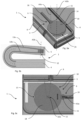
- the rotation shaft 12 extends perpendicular to the hinge assembly rotation axis A1 and the actuator axis A2, with a center axis A3b.
- the cam element 6 is arranged adjacent one side or end of the rotation shaft 12.
- the cam element 6 comprises a circular element 11 which may be plate shaped, and extend in a first plane perpendicular to the center axis of the rotation shaft 12.
- the center axis A3a of the cam element 6 extends in parallel with the center axis A3b of the rotation shaft 12.
- the cam section 10, arranged on the rotation shaft 12, may comprise a circular section 14 extending in the first plane, e.g. in the form of a circular plate or two parallel circular plates, and having an outer diameter which is significantly larger that the diameter of the rotation shaft 12, allowing the required locking forces on the cam element 6 and the cam section 10 to be significantly reduced while keeping the device locking forces the same.
- the circular section 14 comprises at least one peripheral notch 15 adapted for receiving the circular element 11.
- the circular element 11 may be moveable in opposite directions in the first plane, such that the circular element 11 may oscillate in response to rotation of rotation shaft 12 and cam section 10 around center axis A3b, as indicated by means of arrows in Fig. 5c .
- the hinge assembly 1 may comprise a resilient element 16, such as a spring, extending within or in parallel with the first plane.
- the resilient element 16 is arranged such that it biases the circular element 11 towards the cam section 10, keeping the interlock between the cam section 10 and the circular element 11 for at least as long as there is no actuation of the linear actuator 7.
- the hinge assembly 1 comprises a neutral axis N, and the center axis of the rotation shaft 12 may intersect the neutral axis N.
- the first end of the linear drive arrangement 13 engages the rotation shaft 12, extending within e.g. the second frame section 5 and the second end of the linear drive arrangement 13 engages a first location and a second location of an individual hinge blade 9.
- the second end of the linear drive arrangement 13 may also engage the first frame section 4.
- the first location and the second location are located on opposite sides of, and with equidistant spacing from, the neutral axis N, as is clear from Fig. 5b .
- the above-mentioned elongated connection element, connecting the hinge blades 9, may extend along the neutral axis N.
- the center axis A3 of the rotation shaft 12 extends within e.g. the second frame section 5 in the same plane as the neutral axis N.
- the center axis A3b of the rotation shaft 12 extends within e.g. the second frame section 5 perpendicular to the neutral axis N, however, the longitudinal extent of the rotation shaft 12 along its center axis A3b is limited to extending between the display and the optional back cover of the electronic device.
- the linear drive arrangement 13 may comprises a loop, a first loop section 13a and a second loop section 13b extending on opposite sides of, and with equidistant spacing from, the neutral axis N.
- the loop may be open at the second end of the linear drive arrangement 13, as shown in Figs. 2a, 2b , and 5b .
- a first rotation of the rotation shaft 12, in a first direction around the center axis A3, A3b of the rotation shaft 12, rotates the loop in the first direction
- a second rotation of the rotation shaft 12, in a second direction around the center axis A3, A3b of the rotation shaft 12 rotates the loop in the second direction.
- the linear drive arrangement 13 may comprises a chain, as indicated in Fig. 7 , or a wire, as indicated in Fig. 6 .
- the linear drive arrangement 13 comprises a wire it may be partially wound around the rotation shaft 12, as shown in Fig. 2c , and extend through the hinge blades 9 along the actuator axis A2 and on opposite sides of, with equidistant spacing from, the neutral axis N.
- the linear drive arrangement 13 may comprise two separate chain sections 13a, 13b extending in parallel with equidistant spacing from the neutral axis N and on opposite sides of the elongated connection element as suggested in Fig. 2b .
- the chain sections extend through the hinge blades 9 along the actuator axis A2, when the hinge assembly 1 is in the unfolded position P1.
- the rotation shaft 12 may comprise at least one pinion and chain of the linear drive arrangement 13 may be connected to a first rack engaging the pinion at a first location, as shown in Fig. 7 .
- a first rotation of the rotation shaft 12 and the pinion moves the rack in a first direction along the actuator axis A2, hence pulling the chain in the first direction, and an opposite, second rotation of the rotation shaft 12 and the pinion moves the rack in a second direction along the actuator axis A2, hence pushing the chain in the second direction.
- the chain, or a second chain section may be connected to a second rack engaging the pinion at a second location opposite the first location and extending along the actuator axis A2.
- the first rack and the second rack extend on opposite sides of, and with equidistant spacing from, the neutral axis N.
- a first rotation of the rotation shaft 12 and the pinion simultaneously moves the first rack in the first direction and the second rack in the second direction, such that the first rack pulls the chain in the first direction and the second rack, simultaneously, pushes the chain in the second direction.
- An opposite, second rotation of the rotation shaft 12 and the pinion simultaneously moves the first rack in the second direction and the second rack in the first direction, such that the first rack pushes the chain in the second direction and the second rack, simultaneously, pulls the chain in the first direction.
- the present disclosure also relates to an electronic device 17 comprising the above described hinge assembly 1.
- the display 2 and/or the back cover of the electronic device may be fixedly connected to the first frame section 4, and pivoting the first frame section 4 or the second frame section 5 will actuate the linear actuator 7.
- the linear actuator 7 urges the display 2 and/or the back cover to slide in relation to the hinge assembly 1 such that an overlap between the display 2 and/or the back cover and the second frame section 5 varies.
- the overlap between the display 2 and the second frame section 5 is at a minimum when the foldable assembly 1 is in the first folded end position P2a.
- the overlap is at a maximum when the hinge assembly 1 is in the second folded end position P2b, as shown in, e.g., Fig 8 .
- the display 2 or the back cover 2b may be fixedly connected to the first frame section 4 and the second frame section 5.
- the linear actuator 7 urges the second frame section 5 to slide, e.g. on sliding rails, in relation to the hinge assembly 1 such that the distance between the hinge assembly 1 and the second frame section 5 varies, as shown in Fig. 9 .
- the distance between the hinge assembly 1 and the second frame section 5 is at a minimum when the foldable assembly 1 is in the first folded end position P2a, and the distance between the hinge assembly 1 and the second frame section 5 is at a maximum when the foldable assembly 1 is in the second folded end position P2b.
Landscapes
- Engineering & Computer Science (AREA)
- Computer Hardware Design (AREA)
- Theoretical Computer Science (AREA)
- Physics & Mathematics (AREA)
- Human Computer Interaction (AREA)
- General Engineering & Computer Science (AREA)
- General Physics & Mathematics (AREA)
- Signal Processing (AREA)
- Mathematical Physics (AREA)
- Telephone Set Structure (AREA)
- Pivots And Pivotal Connections (AREA)
Claims (12)
- Scharnierbaugruppe (1) für eine elektronische Vorrichtung (17), wobei die Scharnierbaugruppe (1) zwischen einer ausgeklappten Position (P1) und einer eingeklappten Endposition (P2a, P2b) bewegbar ist,wobei die Scharnierbaugruppe (1) eine Reihe miteinander verbundener und aneinander anliegender Scharnierblätter (9) und mindestens einen Linearaktor (7) umfasst,wobei die Scharnierblätter (9) in einer gemeinsamen Ebene ausgerichtet sind, wenn sich die Scharnierbaugruppe (1) in der ausgeklappten Position (P1) befindet, wobei jedes Scharnierblatt (9) in Bezug auf benachbarte Scharnierblätter (9) um eine Scharnierbaugruppendrehachse (A1) gedreht wird, wenn die Scharnierbaugruppe (1) in die eingeklappte Endposition (P2a, P2b) bewegt wird,dadurch gekennzeichnet, dassder Linearaktor (7) eine Drehwelle (12) und mindestens eine Linearantriebsanordnung (13) umfasst,ein erstes Ende der Linearantriebsanordnung (13) mit der Drehwelle (12) verbunden ist,ein zweites, gegenüberliegendes Ende der Linearantriebsanordnung (13) mit mindestens einem Scharnierblatt (9) verbunden ist, wobei sich eine Aktorachse (A2) zwischen dem ersten Ende und dem zweiten Ende und senkrecht zu der Scharnierbaugruppendrehachse (A1) erstreckt,der Linearaktor (7) ferner eine Verriegelungsanordnung (3) zum Verriegeln der Scharnierbaugruppe (1) in mindestens einer der ausgeklappten Position (P1) und der eingeklappten Endposition (P2a, P2b) umfasst,die Verriegelungsanordnung (3) ein Nockenelement (6) umfasst, das mit einem Nockenabschnitt (10) verzahnt ist, der sich auf der Drehwelle (12) befindet.
- Scharnierbaugruppe (1) nach Anspruch 1, wobei sich die Drehwelle (12) parallel zu der Scharnierbaugruppendrehachse (A1) erstreckt und sich die Linearantriebsanordnung (13) entlang der Aktorachse (A2) erstreckt, wobei das Nockenelement (6) einen Abschnitt der Drehwelle (12) umschließt, sodass das Nockenelement (6) und die Drehwelle (12) eine gemeinsame Mittelachse (A3) aufweisen.
- Scharnierbaugruppe (1) nach Anspruch 1, wobei sich die Drehwelle (12) senkrecht zu der Scharnierbaugruppendrehachse (A1) und der Aktorachse (A2) erstreckt,wobei das Nockenelement (6) benachbart zu einem Ende der Drehwelle (12) angeordnet ist,wobei das Nockenelement (6) ein kreisförmiges Element (11) umfasst, das sich in einer ersten Ebene erstreckt, die senkrecht zu einer Mittelachse (A3b) der Drehwelle (12) ist, wobei sich eine Mittelachse (A3a) des kreisförmigen Elements (11) parallel zu der Mittelachse (A3b) der Drehwelle (12) erstreckt, wobei der Nockenabschnitt (10) einen kreisförmigen Abschnitt (14) umfasst, der sich in der ersten Ebene erstreckt und mindestens eine periphere Kerbe (15) umfasst, die zum Aufnehmen des kreisförmigen Elements (11) ausgelegt ist.
- Scharnierbaugruppe (1) nach einem der vorhergehenden Ansprüche, ferner umfassend ein federndes Element (16), das das Nockenelement (6) in Richtung des Nockenabschnitts (10) vorspannt.
- Scharnierbaugruppe (1) nach Anspruch 4, wobei das federnde Element (16) eine Feder umfasst.
- Scharnierbaugruppe (1) nach einem der vorhergehenden Ansprüche, wobei die Scharnierbaugruppe (1) eine neutrale Achse (N) umfasst, wobei eine Mittelachse (A3, A3b) der Drehwelle (12) die neutrale Achse (N) schneidet, wobei ein erstes Ende der Linearantriebsanordnung (13) mit der Drehwelle (12) in Eingriff steht, wobei ein zweites Ende der Linearantriebsanordnung (13) mit einer ersten Stelle und einer zweiten Stelle eines einzelnen Scharnierblatts (9) in Eingriff steht, wobei die erste Stelle und die zweite Stelle auf gegenüberliegenden Seiten der neutralen Achse (N) liegen und einen gleichen Abstand zu dieser aufweisen.
- Scharnierbaugruppe (1) nach Anspruch 6, wobei die Linearantriebsanordnung (13) eine Schleife, einen ersten Schleifenabschnitt (13a) und einen zweiten Schleifenabschnitt (13b) umfasst, die sich auf gegenüberliegenden Seiten der neutralen Achse (N) erstrecken und einen gleichen Abstand zu dieser aufweisen, wobei eine erste Drehung der Drehwelle (12) die Schleife in eine erste Richtung dreht und eine zweite Drehung der Drehwelle (12) die Schleife in eine zweite Richtung dreht.
- Scharnierbaugruppe (1) nach einem der vorhergehenden Ansprüche, wobei die Linearantriebsanordnung (13) eine Kette oder einen Draht umfasst.
- Scharnierbaugruppe (1) nach einem der vorhergehenden Ansprüche, wobei der Draht teilweise um die Drehwelle (12) gewickelt ist.
- Scharnierbaugruppe (1) nach einem der vorhergehenden Ansprüche, wobei eine erste Abmessung (D1) einer ersten Außenfläche (8a) der Scharnierbaugruppe (1) größer als eine entsprechende zweite Abmessung (D2) einer zweiten Außenfläche (8b) der Scharnierbaugruppe (1) ist, wenn sich die Scharnierbaugruppe (1) in der eingeklappten Endposition (P2a, P2b) befindet, wobei der Linearaktor (7) durch eine Differenz zwischen der ersten Abmessung (D1) und der zweiten Abmessung (D2) aktiviert wird.
- Elektronische Vorrichtung (17), umfassend einen ersten Rahmenabschnitt (4), einen zweiten Rahmenabschnitt (5), eine Anzeige (2), die mit mindestens einem des ersten Rahmenabschnitts (4) und des zweiten Rahmenabschnitts (5) verbunden ist, und eine Scharnierbaugruppe (1) nach einem der Ansprüche 1 bis 10, die den ersten Rahmenabschnitt (4) und den zweiten Rahmenabschnitt (5) derart miteinander verbindet, dass der erste Rahmenabschnitt (4) und der zweite Rahmenabschnitt (5) in Bezug aufeinander zwischen einer ausgeklappten Position (P1) und einer ersten eingeklappten Endposition (P2a) schwenkbar sind,
wobei der erste Rahmenabschnitt (4) und der zweite Rahmenabschnitt (5) in der ausgeklappten Position (P1) in einer gemeinsamen Ebene ausgerichtet und lösbar verriegelt sind, wobei der zweite Rahmenabschnitt (5) in der ersten eingeklappten Endposition (P2a) auf dem ersten Rahmenabschnitt (4) überlagert und lösbar verriegelt ist. - Elektronische Vorrichtung (17) nach Anspruch 11, wobei die Scharnierbaugruppe (1) den ersten Rahmenabschnitt (4) und den zweiten Rahmenabschnitt (5) derart miteinander verbindet, dass der erste Rahmenabschnitt (4) und der zweite Rahmenabschnitt (5) in Bezug aufeinander zwischen einer ausgeklappten Position (P1) und einer zweiten eingeklappten Endposition (P2b) schwenkbar sind, wobei der erste Rahmenabschnitt (4) in der zweiten eingeklappten Endposition (P2b) auf dem zweiten Rahmenabschnitt (5) überlagert und lösbar verriegelt ist.
Applications Claiming Priority (1)
| Application Number | Priority Date | Filing Date | Title |
|---|---|---|---|
| PCT/EP2019/078629 WO2021078362A1 (en) | 2019-10-22 | 2019-10-22 | Locking arrangement for a foldable electronic device |
Publications (2)
| Publication Number | Publication Date |
|---|---|
| EP4029226A1 EP4029226A1 (de) | 2022-07-20 |
| EP4029226B1 true EP4029226B1 (de) | 2024-12-11 |
Family
ID=68318889
Family Applications (1)
| Application Number | Title | Priority Date | Filing Date |
|---|---|---|---|
| EP19791235.5A Active EP4029226B1 (de) | 2019-10-22 | 2019-10-22 | Verriegelungsanordnung für ein klappbares elektronisches gerät |
Country Status (4)
| Country | Link |
|---|---|
| US (1) | US12206807B2 (de) |
| EP (1) | EP4029226B1 (de) |
| CN (1) | CN114586329B (de) |
| WO (1) | WO2021078362A1 (de) |
Families Citing this family (1)
| Publication number | Priority date | Publication date | Assignee | Title |
|---|---|---|---|---|
| US10426051B2 (en) | 2017-12-27 | 2019-09-24 | Intel Corporation | Folding devices |
Family Cites Families (5)
| Publication number | Priority date | Publication date | Assignee | Title |
|---|---|---|---|---|
| KR100457749B1 (ko) | 2001-11-21 | 2004-11-18 | 피닉스코리아 주식회사 | 힌지장치 |
| US7173825B2 (en) * | 2001-11-21 | 2007-02-06 | Phoenix Korea Co., Ltd. | Hinge device and electronic device using the same |
| US9348362B2 (en) * | 2013-02-08 | 2016-05-24 | Samsung Electronics Co., Ltd. | Flexible portable terminal |
| KR102509046B1 (ko) * | 2018-02-02 | 2023-03-10 | 삼성디스플레이 주식회사 | 폴더블 디바이스 및 그 제어 방법 |
| TWM563489U (zh) * | 2018-03-07 | 2018-07-11 | 富世達股份有限公司 | 連動定位機構及可撓式電子裝置 |
-
2019
- 2019-10-22 CN CN201980101514.7A patent/CN114586329B/zh active Active
- 2019-10-22 EP EP19791235.5A patent/EP4029226B1/de active Active
- 2019-10-22 US US17/770,180 patent/US12206807B2/en active Active
- 2019-10-22 WO PCT/EP2019/078629 patent/WO2021078362A1/en not_active Ceased
Also Published As
| Publication number | Publication date |
|---|---|
| WO2021078362A1 (en) | 2021-04-29 |
| US12206807B2 (en) | 2025-01-21 |
| US20220303369A1 (en) | 2022-09-22 |
| CN114586329B (zh) | 2023-06-06 |
| CN114586329A (zh) | 2022-06-03 |
| EP4029226A1 (de) | 2022-07-20 |
Similar Documents
| Publication | Publication Date | Title |
|---|---|---|
| JP7534437B2 (ja) | 裏折りフレキシブルスクリーン端末に用いる運動機構 | |
| US10480225B1 (en) | Hinge mechanism and flexible electronic device having the same | |
| US10070546B1 (en) | Bendable display apparatus and supporting device | |
| US7187554B2 (en) | Movable console device | |
| US20240040021A1 (en) | Hinge with lifting drive control function, and inward-folding flexible screen mobile terminal | |
| KR20200103111A (ko) | 접이식 지지 장치 및 접이식 플렉서블 디스플레이 장치 | |
| US20060205451A1 (en) | Slide apparatus, slide module and electronic device utilizing the same | |
| CN110611726B (zh) | 柔性屏移动终端铰链及柔性屏移动终端 | |
| US20240044360A1 (en) | Novel hinge and inward-folding flexible screen mobile terminal | |
| EP4029226B1 (de) | Verriegelungsanordnung für ein klappbares elektronisches gerät | |
| WO2020124788A1 (zh) | 铰链装置及电子装置 | |
| JP4360593B2 (ja) | ヒンジ構造及びモバイル情報端末機器 | |
| CN115030951A (zh) | 铰链、柔性显示面板及显示终端 | |
| CN116498643A (zh) | 一种转轴机构及终端设备 | |
| TWI465180B (zh) | 用來固定配件模組於可攜式電子裝置之固定機構 | |
| JP4781473B1 (ja) | ばねユニット及びスライド機構 | |
| CN103076844B (zh) | 滑盖式电子装置 | |
| US20110007469A1 (en) | Slider actuator | |
| JP5289362B2 (ja) | 可動コンソール装置 | |
| EP4026305B9 (de) | Scharnieranordnung zum kontrollierten zusammenklappen einer elektronischen vorrichtung | |
| EP4029228B1 (de) | Gleitende anzeigevorrichtung für eine klappbare elektronische vorrichtung | |
| JP5409494B2 (ja) | 回転型表示装置 | |
| JP2008095935A (ja) | 平行二軸ヒンジモジュール | |
| CN216657955U (zh) | 机器人头部机构 | |
| JP4767921B2 (ja) | 携帯端末装置 |
Legal Events
| Date | Code | Title | Description |
|---|---|---|---|
| STAA | Information on the status of an ep patent application or granted ep patent |
Free format text: STATUS: UNKNOWN |
|
| STAA | Information on the status of an ep patent application or granted ep patent |
Free format text: STATUS: THE INTERNATIONAL PUBLICATION HAS BEEN MADE |
|
| PUAI | Public reference made under article 153(3) epc to a published international application that has entered the european phase |
Free format text: ORIGINAL CODE: 0009012 |
|
| STAA | Information on the status of an ep patent application or granted ep patent |
Free format text: STATUS: REQUEST FOR EXAMINATION WAS MADE |
|
| 17P | Request for examination filed |
Effective date: 20220412 |
|
| AK | Designated contracting states |
Kind code of ref document: A1 Designated state(s): AL AT BE BG CH CY CZ DE DK EE ES FI FR GB GR HR HU IE IS IT LI LT LU LV MC MK MT NL NO PL PT RO RS SE SI SK SM TR |
|
| DAV | Request for validation of the european patent (deleted) | ||
| DAX | Request for extension of the european patent (deleted) | ||
| GRAP | Despatch of communication of intention to grant a patent |
Free format text: ORIGINAL CODE: EPIDOSNIGR1 |
|
| STAA | Information on the status of an ep patent application or granted ep patent |
Free format text: STATUS: GRANT OF PATENT IS INTENDED |
|
| INTG | Intention to grant announced |
Effective date: 20240702 |
|
| GRAS | Grant fee paid |
Free format text: ORIGINAL CODE: EPIDOSNIGR3 |
|
| GRAA | (expected) grant |
Free format text: ORIGINAL CODE: 0009210 |
|
| STAA | Information on the status of an ep patent application or granted ep patent |
Free format text: STATUS: THE PATENT HAS BEEN GRANTED |
|
| AK | Designated contracting states |
Kind code of ref document: B1 Designated state(s): AL AT BE BG CH CY CZ DE DK EE ES FI FR GB GR HR HU IE IS IT LI LT LU LV MC MK MT NL NO PL PT RO RS SE SI SK SM TR |
|
| REG | Reference to a national code |
Ref country code: GB Ref legal event code: FG4D |
|
| REG | Reference to a national code |
Ref country code: CH Ref legal event code: EP |
|
| REG | Reference to a national code |
Ref country code: DE Ref legal event code: R096 Ref document number: 602019063427 Country of ref document: DE |
|
| REG | Reference to a national code |
Ref country code: IE Ref legal event code: FG4D |
|
| REG | Reference to a national code |
Ref country code: NL Ref legal event code: FP |
|
| REG | Reference to a national code |
Ref country code: LT Ref legal event code: MG9D |
|
| PG25 | Lapsed in a contracting state [announced via postgrant information from national office to epo] |
Ref country code: HR Free format text: LAPSE BECAUSE OF FAILURE TO SUBMIT A TRANSLATION OF THE DESCRIPTION OR TO PAY THE FEE WITHIN THE PRESCRIBED TIME-LIMIT Effective date: 20241211 |
|
| PG25 | Lapsed in a contracting state [announced via postgrant information from national office to epo] |
Ref country code: FI Free format text: LAPSE BECAUSE OF FAILURE TO SUBMIT A TRANSLATION OF THE DESCRIPTION OR TO PAY THE FEE WITHIN THE PRESCRIBED TIME-LIMIT Effective date: 20241211 |
|
| PG25 | Lapsed in a contracting state [announced via postgrant information from national office to epo] |
Ref country code: BG Free format text: LAPSE BECAUSE OF FAILURE TO SUBMIT A TRANSLATION OF THE DESCRIPTION OR TO PAY THE FEE WITHIN THE PRESCRIBED TIME-LIMIT Effective date: 20241211 |
|
| PG25 | Lapsed in a contracting state [announced via postgrant information from national office to epo] |
Ref country code: ES Free format text: LAPSE BECAUSE OF FAILURE TO SUBMIT A TRANSLATION OF THE DESCRIPTION OR TO PAY THE FEE WITHIN THE PRESCRIBED TIME-LIMIT Effective date: 20241211 |
|
| PG25 | Lapsed in a contracting state [announced via postgrant information from national office to epo] |
Ref country code: NO Free format text: LAPSE BECAUSE OF FAILURE TO SUBMIT A TRANSLATION OF THE DESCRIPTION OR TO PAY THE FEE WITHIN THE PRESCRIBED TIME-LIMIT Effective date: 20250311 |
|
| PG25 | Lapsed in a contracting state [announced via postgrant information from national office to epo] |
Ref country code: LV Free format text: LAPSE BECAUSE OF FAILURE TO SUBMIT A TRANSLATION OF THE DESCRIPTION OR TO PAY THE FEE WITHIN THE PRESCRIBED TIME-LIMIT Effective date: 20241211 Ref country code: GR Free format text: LAPSE BECAUSE OF FAILURE TO SUBMIT A TRANSLATION OF THE DESCRIPTION OR TO PAY THE FEE WITHIN THE PRESCRIBED TIME-LIMIT Effective date: 20250312 |
|
| PG25 | Lapsed in a contracting state [announced via postgrant information from national office to epo] |
Ref country code: RS Free format text: LAPSE BECAUSE OF FAILURE TO SUBMIT A TRANSLATION OF THE DESCRIPTION OR TO PAY THE FEE WITHIN THE PRESCRIBED TIME-LIMIT Effective date: 20250311 |
|
| REG | Reference to a national code |
Ref country code: AT Ref legal event code: MK05 Ref document number: 1751273 Country of ref document: AT Kind code of ref document: T Effective date: 20241211 |
|
| PG25 | Lapsed in a contracting state [announced via postgrant information from national office to epo] |
Ref country code: SM Free format text: LAPSE BECAUSE OF FAILURE TO SUBMIT A TRANSLATION OF THE DESCRIPTION OR TO PAY THE FEE WITHIN THE PRESCRIBED TIME-LIMIT Effective date: 20241211 |
|
| PG25 | Lapsed in a contracting state [announced via postgrant information from national office to epo] |
Ref country code: PL Free format text: LAPSE BECAUSE OF FAILURE TO SUBMIT A TRANSLATION OF THE DESCRIPTION OR TO PAY THE FEE WITHIN THE PRESCRIBED TIME-LIMIT Effective date: 20241211 |
|
| PG25 | Lapsed in a contracting state [announced via postgrant information from national office to epo] |
Ref country code: IS Free format text: LAPSE BECAUSE OF FAILURE TO SUBMIT A TRANSLATION OF THE DESCRIPTION OR TO PAY THE FEE WITHIN THE PRESCRIBED TIME-LIMIT Effective date: 20250411 |
|
| PG25 | Lapsed in a contracting state [announced via postgrant information from national office to epo] |
Ref country code: PT Free format text: LAPSE BECAUSE OF FAILURE TO SUBMIT A TRANSLATION OF THE DESCRIPTION OR TO PAY THE FEE WITHIN THE PRESCRIBED TIME-LIMIT Effective date: 20250411 |
|
| PG25 | Lapsed in a contracting state [announced via postgrant information from national office to epo] |
Ref country code: EE Free format text: LAPSE BECAUSE OF FAILURE TO SUBMIT A TRANSLATION OF THE DESCRIPTION OR TO PAY THE FEE WITHIN THE PRESCRIBED TIME-LIMIT Effective date: 20241211 |
|
| PG25 | Lapsed in a contracting state [announced via postgrant information from national office to epo] |
Ref country code: AT Free format text: LAPSE BECAUSE OF FAILURE TO SUBMIT A TRANSLATION OF THE DESCRIPTION OR TO PAY THE FEE WITHIN THE PRESCRIBED TIME-LIMIT Effective date: 20241211 Ref country code: RO Free format text: LAPSE BECAUSE OF FAILURE TO SUBMIT A TRANSLATION OF THE DESCRIPTION OR TO PAY THE FEE WITHIN THE PRESCRIBED TIME-LIMIT Effective date: 20241211 |
|
| PG25 | Lapsed in a contracting state [announced via postgrant information from national office to epo] |
Ref country code: SK Free format text: LAPSE BECAUSE OF FAILURE TO SUBMIT A TRANSLATION OF THE DESCRIPTION OR TO PAY THE FEE WITHIN THE PRESCRIBED TIME-LIMIT Effective date: 20241211 |
|
| PG25 | Lapsed in a contracting state [announced via postgrant information from national office to epo] |
Ref country code: CZ Free format text: LAPSE BECAUSE OF FAILURE TO SUBMIT A TRANSLATION OF THE DESCRIPTION OR TO PAY THE FEE WITHIN THE PRESCRIBED TIME-LIMIT Effective date: 20241211 |
|
| PG25 | Lapsed in a contracting state [announced via postgrant information from national office to epo] |
Ref country code: IT Free format text: LAPSE BECAUSE OF FAILURE TO SUBMIT A TRANSLATION OF THE DESCRIPTION OR TO PAY THE FEE WITHIN THE PRESCRIBED TIME-LIMIT Effective date: 20241211 |
|
| PG25 | Lapsed in a contracting state [announced via postgrant information from national office to epo] |
Ref country code: SE Free format text: LAPSE BECAUSE OF FAILURE TO SUBMIT A TRANSLATION OF THE DESCRIPTION OR TO PAY THE FEE WITHIN THE PRESCRIBED TIME-LIMIT Effective date: 20241211 |
|
| REG | Reference to a national code |
Ref country code: DE Ref legal event code: R097 Ref document number: 602019063427 Country of ref document: DE |
|
| PG25 | Lapsed in a contracting state [announced via postgrant information from national office to epo] |
Ref country code: DK Free format text: LAPSE BECAUSE OF FAILURE TO SUBMIT A TRANSLATION OF THE DESCRIPTION OR TO PAY THE FEE WITHIN THE PRESCRIBED TIME-LIMIT Effective date: 20241211 |
|
| PGFP | Annual fee paid to national office [announced via postgrant information from national office to epo] |
Ref country code: NL Payment date: 20250912 Year of fee payment: 7 |
|
| PLBE | No opposition filed within time limit |
Free format text: ORIGINAL CODE: 0009261 |
|
| STAA | Information on the status of an ep patent application or granted ep patent |
Free format text: STATUS: NO OPPOSITION FILED WITHIN TIME LIMIT |
|
| 26N | No opposition filed |
Effective date: 20250912 |
|
| PGFP | Annual fee paid to national office [announced via postgrant information from national office to epo] |
Ref country code: DE Payment date: 20250902 Year of fee payment: 7 |