EP4029228B1 - Gleitende anzeigevorrichtung für eine klappbare elektronische vorrichtung - Google Patents
Gleitende anzeigevorrichtung für eine klappbare elektronische vorrichtung Download PDFInfo
- Publication number
- EP4029228B1 EP4029228B1 EP19794497.8A EP19794497A EP4029228B1 EP 4029228 B1 EP4029228 B1 EP 4029228B1 EP 19794497 A EP19794497 A EP 19794497A EP 4029228 B1 EP4029228 B1 EP 4029228B1
- Authority
- EP
- European Patent Office
- Prior art keywords
- axis
- actuator
- surface layer
- foldable assembly
- linear
- Prior art date
- Legal status (The legal status is an assumption and is not a legal conclusion. Google has not performed a legal analysis and makes no representation as to the accuracy of the status listed.)
- Active
Links
Images


Classifications
-
- H—ELECTRICITY
- H04—ELECTRIC COMMUNICATION TECHNIQUE
- H04M—TELEPHONIC COMMUNICATION
- H04M1/00—Substation equipment, e.g. for use by subscribers
- H04M1/02—Constructional features of telephone sets
- H04M1/0202—Portable telephone sets, e.g. cordless phones, mobile phones or bar type handsets
- H04M1/0206—Portable telephones comprising a plurality of mechanically joined movable body parts, e.g. hinged housings
- H04M1/0208—Portable telephones comprising a plurality of mechanically joined movable body parts, e.g. hinged housings characterized by the relative motions of the body parts
- H04M1/0214—Foldable telephones, i.e. with body parts pivoting to an open position around an axis parallel to the plane they define in closed position
- H04M1/0216—Foldable in one direction, i.e. using a one degree of freedom hinge
-
- G—PHYSICS
- G06—COMPUTING OR CALCULATING; COUNTING
- G06F—ELECTRIC DIGITAL DATA PROCESSING
- G06F1/00—Details not covered by groups G06F3/00 - G06F13/00 and G06F21/00
- G06F1/16—Constructional details or arrangements
- G06F1/1613—Constructional details or arrangements for portable computers
- G06F1/1633—Constructional details or arrangements of portable computers not specific to the type of enclosures covered by groups G06F1/1615 - G06F1/1626
- G06F1/1637—Details related to the display arrangement, including those related to the mounting of the display in the housing
- G06F1/1641—Details related to the display arrangement, including those related to the mounting of the display in the housing the display being formed by a plurality of foldable display components
-
- G—PHYSICS
- G06—COMPUTING OR CALCULATING; COUNTING
- G06F—ELECTRIC DIGITAL DATA PROCESSING
- G06F1/00—Details not covered by groups G06F3/00 - G06F13/00 and G06F21/00
- G06F1/16—Constructional details or arrangements
- G06F1/1613—Constructional details or arrangements for portable computers
- G06F1/1633—Constructional details or arrangements of portable computers not specific to the type of enclosures covered by groups G06F1/1615 - G06F1/1626
- G06F1/1637—Details related to the display arrangement, including those related to the mounting of the display in the housing
- G06F1/1652—Details related to the display arrangement, including those related to the mounting of the display in the housing the display being flexible, e.g. mimicking a sheet of paper, or rollable
-
- G—PHYSICS
- G06—COMPUTING OR CALCULATING; COUNTING
- G06F—ELECTRIC DIGITAL DATA PROCESSING
- G06F1/00—Details not covered by groups G06F3/00 - G06F13/00 and G06F21/00
- G06F1/16—Constructional details or arrangements
- G06F1/1613—Constructional details or arrangements for portable computers
- G06F1/1633—Constructional details or arrangements of portable computers not specific to the type of enclosures covered by groups G06F1/1615 - G06F1/1626
- G06F1/1675—Miscellaneous details related to the relative movement between the different enclosures or enclosure parts
- G06F1/1681—Details related solely to hinges
-
- H—ELECTRICITY
- H04—ELECTRIC COMMUNICATION TECHNIQUE
- H04M—TELEPHONIC COMMUNICATION
- H04M1/00—Substation equipment, e.g. for use by subscribers
- H04M1/02—Constructional features of telephone sets
- H04M1/0202—Portable telephone sets, e.g. cordless phones, mobile phones or bar type handsets
- H04M1/0206—Portable telephones comprising a plurality of mechanically joined movable body parts, e.g. hinged housings
- H04M1/0208—Portable telephones comprising a plurality of mechanically joined movable body parts, e.g. hinged housings characterized by the relative motions of the body parts
- H04M1/0235—Slidable or telescopic telephones, i.e. with a relative translation movement of the body parts; Telephones using a combination of translation and other relative motions of the body parts
- H04M1/0237—Sliding mechanism with one degree of freedom
-
- H—ELECTRICITY
- H04—ELECTRIC COMMUNICATION TECHNIQUE
- H04M—TELEPHONIC COMMUNICATION
- H04M1/00—Substation equipment, e.g. for use by subscribers
- H04M1/02—Constructional features of telephone sets
- H04M1/0202—Portable telephone sets, e.g. cordless phones, mobile phones or bar type handsets
- H04M1/026—Details of the structure or mounting of specific components
- H04M1/0266—Details of the structure or mounting of specific components for a display module assembly
- H04M1/0268—Details of the structure or mounting of specific components for a display module assembly including a flexible display panel
-
- G—PHYSICS
- G06—COMPUTING OR CALCULATING; COUNTING
- G06F—ELECTRIC DIGITAL DATA PROCESSING
- G06F2203/00—Indexing scheme relating to G06F3/00 - G06F3/048
- G06F2203/041—Indexing scheme relating to G06F3/041 - G06F3/045
- G06F2203/04102—Flexible digitiser, i.e. constructional details for allowing the whole digitising part of a device to be flexed or rolled like a sheet of paper
-
- H—ELECTRICITY
- H04—ELECTRIC COMMUNICATION TECHNIQUE
- H04M—TELEPHONIC COMMUNICATION
- H04M1/00—Substation equipment, e.g. for use by subscribers
- H04M1/02—Constructional features of telephone sets
- H04M1/0202—Portable telephone sets, e.g. cordless phones, mobile phones or bar type handsets
- H04M1/0206—Portable telephones comprising a plurality of mechanically joined movable body parts, e.g. hinged housings
- H04M1/0208—Portable telephones comprising a plurality of mechanically joined movable body parts, e.g. hinged housings characterized by the relative motions of the body parts
- H04M1/0214—Foldable telephones, i.e. with body parts pivoting to an open position around an axis parallel to the plane they define in closed position
- H04M1/0216—Foldable in one direction, i.e. using a one degree of freedom hinge
- H04M1/022—The hinge comprising two parallel pivoting axes
Definitions
- the disclosure relates to a foldable assembly for an electronic device, the foldable assembly comprising a foldable surface layer superimposed onto a foldable support layer, the support layer comprising a first body, a second body, and a pivot hinge.
- the size of electronic devices is an important consideration when designing electronic devices.
- the user oftentimes requests the outer dimensions of the device to be as small as possible while still providing a display which is as large as possible.
- This problem may be solved, e.g., by means of a foldable electronic device comprising one or several support bodies, e.g. interconnected by means of hinges, covered by a display.
- the support body/bodies and the display can be folded together to provide an as small electronic device as possible, and unfolded to provide an as large display as possible.
- the neutral axis is the axis along which the display or the housing remains unchanged as it is folded, i.e. it neither stretches nor compresses.
- EP 2 765 479 A2 describes a flexible portable terminal that includes a folding portion configured to bend at one end of a body of the flexible portable terminal in a direction to a front surface or a rear surface of the flexible portable terminal, a flexible display unit configured to be mounted on the body of the flexible portable terminal, and to bend in the front surface or the rear surface of the flexible portable terminal according to a bending direction of the folding portion, and a sliding portion configured to enable one end of the flexible display unit to slide according to a difference of a compression/tension caused by a difference of an elongation between the folding portion and the flexible display unit when the folding portion is bent.
- US 2012/314399 A1 describes a foldable assembly that includes first flanges integrated in a first housing part of a foldable electronic device.
- the foldable electronic device includes a flexible display, and the first housing part is integrated with a first section of the flexible display.
- the foldable assembly also includes second flanges integrated in a second housing part of the foldable electronic device, and the second housing part is integrated with a second section of the flexible display.
- the second flanges are implemented to fold-interlock with the first flanges to form a bend radius of the flexible display around the first and second flanges in a closed position of the foldable electronic device.
- the first and second flanges are also implemented to support the flexible display in the closed position of the foldable electronic device.
- US 2013/10405A1 describes electronic devices that contain multiple housing portions.
- the housing portions may be coupled together using hinges.
- the hinges may include hinges based on a three-bar linkage, hinges based on a four-bar linkage, hinges with slotted members, hinges formed from flexible support structures, and hinges based on flexible housing structures.
- Flexible displays may be mounted to the housing portions overlapping the hinges. When the housing portions in a device are rotated relative to each other, the flexible display may bend.
- the hinge may be configured to allow the flexible display to be placed in a front-to-front configuration in which an active side of the display faces itself or a back-to-back configuration.
- Engagement structures may be used to help the housing grip external objects and to hold the housing portions together.
- the hinges may be provided with rotational detents to help hold the flexible display in desired positions.
- the rotation shaft extends in parallel with the assembly rotation axis, a rotation shaft center axis intersecting the first neutral axis.
- the first linear drive arrangement and/or the second linear drive arrangement comprises at least one of a chain, a wire, a rack, and a sheet.
- the first linear drive arrangement comprises at least one folding section, extending through the pivot hinge, and at least one linear section interconnected with the folding section, and the rotation shaft comprises a first pinion, the linear section comprising a first rack engaging the first pinion at a first location and extending along the actuator axis.
- movement of the first rack in a first direction along the actuator axis initiates a first rotation of the first pinion and the rotation shaft
- movement of the first rack in an opposite, second direction along the actuator axis initiates an opposite, second rotation of the first pinion and the rotation shaft
- the linear section further comprises a second rack engaging the first pinion at a second location opposite the first location and extending along the actuator axis, the first rack and the second rack extending on opposite sides of, and with equidistant spacing from, the first neutral axis.
- simultaneous movement of the first rack in the first direction and the second rack in the second direction along the actuator axis initiates the first rotation of the first pinion and the rotation shaft, and wherein simultaneous movement of the first rack in the second direction and the second rack in the first direction along the actuator axis initiates the second rotation of the first pinion and the rotation shaft.
- the rotation shaft comprises a second pinion
- the second linear drive arrangement comprises a third rack engaging the second pinion at a first location and extending along the actuator axis.
- the second linear drive arrangement further comprises a fourth rack engaging the second pinion at a second location opposite the first location and extending along the actuator axis, the third rack and the fourth rack extending on opposite sides of, and with equidistant spacing from, the first neutral axis.
- first linear drive arrangement and the second linear drive arrangement each comprise at least two wire sections extending on opposite sides of, with equidistant spacing from, the first neutral axis.
- movement of the first linear drive arrangement along the actuator axis initiates one of a first rotation or an opposite second rotation of the rotation shaft, the first rotation or the second rotation of the rotation shaft initiating a corresponding movement of the second linear drive arrangement along the actuator axis, allowing the movement of the surface layers to be synchronized and simultaneous.
- the foldable assembly further comprises a motor adapted for rotating the rotation shaft, and wherein rotation of the rotation shaft initiates movement of at least one of the first linear drive arrangement and the second linear drive arrangement along the actuator axis.
- the foldable assembly comprises at least one intermediate layer located between the first surface layer and the support layer, or between the second surface layer and the support layer, and the rotation shaft comprises pinions and/or sections having different diameters, one linear drive arrangement being interconnected with each pinion or shaft diameter section, and each linear drive arrangement being connected to one of the first surface layer, the second surface layer, and the intermediate layer.
- an electronic device comprising the foldable assembly according to the above, the foldable assembly being moveable between an unfolded position and a first folded end position, the first surface layer of the foldable assembly comprising a display, and/or the second surface layer of the foldable assembly comprising a back cover, the support layer supporting at least one of the first surface layer and the second surface layer.
- This allows the surface layer and/or the support body/bodies of the electronic device to slide in relation to each other, as the electronic device is folded, hence preventing the surface layer from becoming wrinkled and/or permanently deformed since the surface layer and the support body/bodies neither stretches nor compresses as the device is folded.
- the solution provides support to the surface layer which extends from one body to another across the foldable assembly.
- the display and/or the back cover is fixedly connected to the first body of the support layer, and pivoting the first body or the second body of the support layer around the pivot hinge of the support layer actuates the linear actuator of the support layer, the linear actuator urging the display and/or the back cover to slide in relation to the pivot hinge such that an overlap between the display and/or the back cover and the second body varies, overlap between the display and the second body being at a minimum when the foldable assembly is in the first folded end position and/or overlap between the back cover and the second body being at a maximum when the foldable assembly is in the first folded end position, avoiding any stress on the display during folding as the display is not affected by any dimensional changes.
- the foldable assembly is moveable between an unfolded position and a second folded end position, the overlap between the display and the second body being at a maximum when the foldable assembly is in the second folded end position and/or the overlap between the back cover and the second body being at a minimum when the foldable assembly is in the second folded end position.
- the display or the back cover is fixedly connected to the first body and second body of the support layer, the support layer furthermore comprising sliding rails interconnecting the pivot hinge of the support layer and the second body, and pivoting the first body or the second body around the pivot hinge actuates the linear actuator of the support layer, the linear actuator urging the second body to slide, on the sliding rails, in relation to the pivot hinge such that the distance between the pivot hinge and the second body varies, the distance between the pivot hinge and the second body being at a minimum when the foldable assembly is in the first folded end position.
- the sliding rails provide support for the display and/or the back cover, and since any sliding movement is maintained within the support layer neither the display nor the back cover is affected when folding.
- the foldable assembly is moveable between an unfolded position and a second folded end position, the distance between the pivot hinge and the second body being at a maximum when the foldable assembly is in the second folded end position.
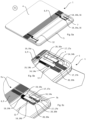
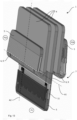
- Figs. 9 to 12 show an electronic device 18 comprising a display 2a, a back cover 2b, and a foldable assembly 1 which is moveable between an unfolded position P1 and at least a first folded end position P2a.
- the foldable assembly 1 is also moveable between the unfolded position P1 and a second folded end position P2b.
- the electronic device 18 is also folded from an unfolded position to a folded end position.
- the foldable assembly 1 comprises a foldable first surface layer 2a, such as the above-mentioned display, which is superimposed onto a foldable support layer 3.
- the support layer 3 comprises, as shown in Figs. 2, 3a, and 3b , a first body 4, a second body 5, and a pivot hinge 6, the pivot hinge 6 interconnecting the first body 4 and the second body 5.
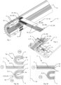
- One embodiment of the pivot hinge 6 is shown in detail in Fig. 1 .
- the first body 4 and the second body 5 are pivotable relative each other around an assembly rotation axis A1 of the pivot hinge 6 such that the foldable assembly 1, and hence the electronic device 18, is moveable between an unfolded position P1 and at least one folded end position P2a, P2b.
- the first body 4 and the second body 5 are aligned in a common plane when the foldable assembly 1 is in the unfolded position P1.
- the second body 5 is superimposed onto the first body 4 when the foldable assembly 1 is in the first folded end position P2a. Furthermore, the first body 4 is superimposed onto the second body 5 when the foldable assembly 1 is in the second folded end position P2b.
- the support layer 3 further comprises at least one linear actuator 7, as shown in Figs. 5a to 6b .
- a first end 7a of the linear actuator 7 is connected to the first body 4 and a second, opposite end 7b of the linear actuator 7 is connected to either the first surface layer 2a, as indicated in Figs. 9 and 10 , or to the second body 5, as indicated in Fig. 13 .
- the connection may be fixed using, e.g., adhesive or fasteners such as screws.
- An actuator axis A2 extends between the first 7a and second 7b ends of the linear actuator 7, and perpendicular to the assembly rotation axis A1.
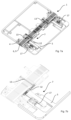
- the linear actuator 7 is actuated such that it urges one of the first surface layer 2a and the second body 5 to move, in relation to the pivot hinge 6, along the actuator axis A2. Movement of the first surface layer 2a in relation to the pivot hinge 6 is shown in Fig. 11 . Movement of the second body 5 in relation to the pivot hinge 6 is shown in Fig. 12 .
- the support layer 3 may have a first neutral axis N1 and the first surface layer 2a a second neutral axis N2, the first neutral axis N1 extending parallel with the second neutral axis N2.
- the first neutral axis N1 is offset from the second neutral axis N2 along an offset axis A3 extending perpendicular to the assembly rotation axis A1 and perpendicular to the actuator axis A2.
- a first dimension of a first outer surface 8a of the pivot hinge 6 is larger than a corresponding second dimension of a second outer surface 8b of the pivot hinge 6 when the foldable assembly 1 is in folded end position P2b, as shown in Fig. 3 a.
- the first outer surface 8a of the pivot hinge 6 is smaller than the corresponding second dimension of the second outer surface 8b of the pivot hinge 6 when the foldable assembly 1 is in folded end position P2a, also shown in Fig. 3a .
- the linear actuator 7 is actuated by a difference between the first dimension and the second dimension.
- the dimensions of the first outer surface 8a increases and the first surface layer 2a is pulled in one direction across the pivot hinge 6, as is shown in the uppermost drawing of Fig. 11 .
- the dimensions of the first outer surface 8a decreases and the first surface layer 2a is pulled in the opposite direction across the pivot hinge 6, as is shown in the lowermost drawing of Fig. 11 .
- the foldable assembly 1 may comprise a foldable second surface layer 2b superimposed onto the support layer 3, the second end 7b of the linear actuator 7 being connected to at least one of the first surface layer 2a and the second surface layer 2b (not shown).
- the linear actuator 7 urges the first surface layer 2a and the second surface layer 2b to move, in relation to the pivot hinge 6, along the actuator axis A2.
- the first surface layer 2a moves in a first direction
- the second surface layer 2b moves in an opposite second direction along the actuator axis A2. This oppositely directed movement is indicated in Fig. 4a by means of arrows.
- the second surface layer 2b may comprise a third neutral axis (not shown), the third neutral axis extending in parallel with the first neutral axis N1 and the second neutral axis N2.
- the third neutral axis is offset from the second neutral axis N2 along the offset axis A3 and extends on the opposite side of the second neutral axis N2 than the first neutral axis N1.
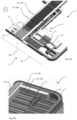
- the support layer 3 may further comprise sliding rails 11 interconnecting the pivot hinge 6 and the second body 5, the sliding rails 11 being arranged to move along the second body 5 along the actuator axis A2 in response to actuation of the linear actuator 7 as is shown in Figs. 12 and 13 .
- the first surface layer 2a and/or the second surface layer 2b are stationary in relation to the first body 4 and the second body 5 of the support layer 3,i.e. the first surface layer 2a and/or the second surface layer 2b are fixed to the first body 4 as well as the second body 5.
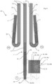
- the pivot hinge 6 preferably comprises a row of at least partially tapered hinge blades 9 interconnected by means of an elongated connection element 10 extending along the actuator axis A2, as shown in Figs. 4a and 4b .
- the hinge blades 9 may be tapered in one direction, as shown in Fig. 3b , or in two directions, as shown in Fig. 3 a.
- One-directional tapering allows the pivot hinge 6 to fold in only one direction, e.g. to first folded end position P2a, while bi-directional tapering allows the pivot hinge 6 to fold in two directions, i.e. to first folded end position P2a as well as second folded end position P2b.
- the linear actuator 7 may comprise a rotation shaft 12, at least one first linear drive arrangement 13, and at least one second linear drive arrangement 17.
- the first linear drive arrangement 13 is interconnected with the rotation shaft 12 and the first body 4, and extends through the pivot hinge 6.
- the second linear drive arrangement 17 is interconnected with the rotation shaft 12.
- the first linear drive arrangement 13 and the second linear drive arrangement 17 are linearly actuated in one direction, or two directions simultaneously, along the actuator axis A2.
- the second linear drive arrangement 17 may be connected to the first surface layer 2a or the second surface layer 2b, the first surface layer 2a and the second surface layer 2b being moved in opposite directions, along the actuator axis A2, when the linear actuator 7 is actuated.
- an opposite, movement the first linear drive arrangement 13 along the actuator axis A2 generates an oppositely directed second rotation of the rotation shaft 12 and the first toothed section 21, which, in turn, results in movement of the second body 5 in a second direction along the actuator axis A2.
- the rotation shaft 12 extends in parallel with the assembly rotation axis A1, such that the rotation shaft 12 center axis intersects the first neutral axis N1, the rotation shaft extending within a neutral plane comprising the first neutral axis N1.
- the first linear drive arrangement 13 and/or the second linear drive arrangement 17 may comprise at least one of a chain, a wire, a rack, and a sheet, or a combination such as a chain and a rack.
- the rotation shaft 12 may comprise pinions 14 and/or sections 16 having different diameters, allowing one first linear drive arrangement 13 or one second linear drive arrangement 17 to be interconnected with each pinion 14 or shaft diameter section 16.
- the first linear drive arrangement 13 may comprise at least one folding section 19, such as a chain, extending through the pivot hinge 6, and at least one linear section 20 interconnected with the folding section 19.
- the rotation shaft 12 may comprise a first pinion 14a
- the linear section 20 comprise a first rack 20a engaging the first pinion 14a at a first location and extend along the actuator axis. Movement of the first rack 20a in a first direction along the actuator axis A2 initiates a first rotation of the first pinion 14a and the rotation shaft 12, and movement of the first rack 20a in an opposite, second direction along the actuator axis A2 initiates an opposite, second rotation of the first pinion 14a and the rotation shaft 12. Movement in the first direction along the actuator axis A2 pulls the folding section 19 in the first direction, and movement in the second direction along the actuator axis A2 pushes the folding section 19 in the second direction.
- the linear section 20 may further comprise a second rack 20b engaging the first pinion 14a at a second location opposite the first location and extending along the actuator axis.
- the first rack 20a and the second rack 20b extend on opposite sides of, and with equidistant spacing from, the first neutral axis N1. Simultaneous movement of the first rack 20a in the first direction and the second rack 20b in the second direction along the actuator axis A2 initiates the first rotation of the first pinion 14a and the rotation shaft 12.
- the rotation shaft 12 may comprise a second pinion 14b, as shown in Figs. 5a to 5c .
- the second linear drive arrangement 17 comprises a third rack 17a engaging the second pinion 14b at a first location and extending along the actuator axis A2.
- the second linear drive arrangement 17 may further comprise a fourth rack 17b engaging the second pinion 14b at a second location opposite the first location and extending along the actuator axis A2.
- the third rack 17a and the fourth rack 17b extend on opposite sides of, and with equidistant spacing from, the first neutral axis N1.
- the first linear drive arrangement 13 and the second linear drive arrangement 17 may each comprise two wire sections extending on opposite sides of, with equidistant spacing from, the first neutral axis N1, as shown in Figs. 7a to 7b .
- the linear drive arrangements 13, 17 comprise a wire it may be partially wound around the rotation shaft 12, as shown in Figs. 6a to 7b , and extend along the actuator axis A2 and on opposite sides of, with equidistant spacing from, the first neutral axis N1.
- a first rotation of the rotation shaft 12 rotates the linear drive arrangement 13 in a first direction
- an opposite, second rotation of the rotation shaft 12 rotates the linear drive arrangement 13 in a second direction.
- the wire may comprise at least two separate wire sections extending in parallel between the first body 4 and the second body 5 of the support layer, or the wire may comprise a loop.
- the foldable assembly 1 may further comprise at least one intermediate layer 15 located between the first surface layer 2a and the support layer 3, or between the second surface layer 2b and the support layer 3.
- the rotation shaft 12 may comprise pinions 14 and/or sections 16 having different diameters, as shown in Fig. 9 , one linear drive arrangement 13 being interconnected with each pinion 14 or shaft diameter section 16, each linear drive arrangement 13 being connected to one of the first surface layer 2a, the second surface layer 2b, and the intermediate layer 15.
- Movement of the first linear drive arrangement 13 along the actuator axis A2 initiates one of a first rotation or an opposite second rotation of the rotation shaft 12, the first rotation or the second rotation of the rotation shaft 12 initiating a corresponding movement of the second linear drive arrangement 17 along the actuator axis A2. This allows the movement of the surface layers 2a, 2b to be synchronized and simultaneous.
- the foldable assembly 1 may further comprise a motor adapted for rotating the rotation shaft 12, and wherein rotation of the rotation shaft 12 initiates movement of at least one of the first linear drive arrangement 13 and the second linear drive arrangement 17 along the actuator axis A2.
- the present disclosure also relates to an electronic device 18 comprising the above described foldable assembly 1.
- the first surface layer 2a of the foldable assembly 1 comprises the display, and/or the second surface layer 2b of the foldable assembly 1 comprises the back cover.
- the support layer 3 supports at least one of the first surface layer/display 2a and the second surface layer/back cover 2b.
- the display 2a and/or the back cover 2b may be fixedly connected to the first body 4 of the support layer 3, and pivoting the first body 4 or the second body 5 of the support layer 3 around the pivot hinge 6 of the support layer 3 will actuate the linear actuator 7.
- the linear actuator 7 urges the display 2a and/or the back cover 2b to slide in relation to the pivot hinge 6 such that an overlap between the display 2a and/or the back cover 2b and the second body 5 varies.
- the overlap between the display 2a and the second body 5 is at a minimum when the foldable assembly 1 is in the first folded end position P2a.
- the overlap between the back cover 2b and the second body 5 is at a maximum when the foldable assembly 1 is in the first folded end position P2a, as shown in, e.g., Fig 11 .
- the display 2a or the back cover 2b may be fixedly connected to the first body 4 and second body 5 of the support layer 3.
- the support layer 3 comprises sliding rails 11 interconnecting the pivot hinge 6 of the support layer 3 and the second body 5, and pivoting the first body 4 or the second body 5 around the pivot hinge 6 actuates the linear actuator 7 of the support layer 3.
- the linear actuator 7 urges the second body 5 to slide, along the sliding rails 11, in relation to the pivot hinge 6 such that the distance between the pivot hinge 6 and the second body 5 varies, as shown in Fig. 12 .
- the distance between the pivot hinge 6 and the second body 5 is at a minimum when the foldable assembly 1 is in the first folded end position P2a.
- the foldable assembly 1 may, correspondingly, be moveable between an unfolded position P1 and a second folded end position P2b, the distance between the pivot hinge 6 and the second body 5 being at a maximum when the foldable assembly 1 is in the second folded end position P2b.
- the overlap between the display 2a and the second body 5 is at a maximum when the foldable assembly 1 is in the second folded end position P2b and/or the overlap between the back cover 2b and the second body 5 is at a minimum when the foldable assembly 1 is in the second folded end position P2b.
Landscapes
- Engineering & Computer Science (AREA)
- Computer Hardware Design (AREA)
- Theoretical Computer Science (AREA)
- Signal Processing (AREA)
- Human Computer Interaction (AREA)
- Physics & Mathematics (AREA)
- General Engineering & Computer Science (AREA)
- General Physics & Mathematics (AREA)
- Telephone Set Structure (AREA)
Claims (15)
- Faltbare Anordnung (1) für eine elektronische Vorrichtung, wobei die faltbare Anordnung (1) eine faltbare erste Oberflächenschicht (2a) umfasst, die eine faltbare Trägerschicht (3) überlagert,wobei die Trägerschicht (3) einen ersten Körper (4), einen zweiten Körper (5) und ein Schwenkscharnier (6) umfasst, wobei das Schwenkscharnier (6) den ersten Körper (4) und den zweiten Körper (5) miteinander verbindet,wobei der erste Körper (4) und der zweite Körper (5) relativ zueinander um eine Anordnungsdrehachse (A1) des Schwenkscharniers (6) schwenkbar sind, so dass die faltbare Anordnung (1) zwischen einer entfalteten Position (P1) und mindestens einer gefalteten Endposition (P2) bewegbar ist,wobei der erste Körper (4) und der zweite Körper (5) in einer gemeinsamen Ebene ausgerichtet sind, wenn sich die faltbare Anordnung (1) in der entfalteten Position (P1) befindet,wobei der erste Körper (4) den zweiten Körper (5) überlagert, wenn sich die faltbare Anordnung (1) in der gefalteten Endposition (P2) befindet,wobei die Trägerschicht (3) ferner mindestens einen Linearaktuator (7) umfasst, der sich mindestens teilweise durch das Schwenkscharnier (6) erstreckt,wobei ein erstes Ende (7a) des Linearaktuators (7) mit dem ersten Körper (4) verbunden ist undein zweites, gegenüberliegendes Ende (7b) des Linearaktuators (7) mit einem von der ersten Oberflächenschicht (2a) und dem zweiten Körper (5) verbunden ist,eine Aktuatorachse (A2), die sich zwischen dem ersten (7a) und zweiten (7b) Ende erstreckt und senkrecht zu der Drehachse (A1) der Anordnung steht,wobei der erste Körper (4) und/oder der zweite Körper (5) dazu geeignet sind, um die Anordnungsdrehachse (A1) zu schwenken und um den Linearaktuator (7) zu betätigen, so dass der Linearaktuator (7) eines von der ersten Oberflächenschicht (2a) und dem zweiten Körper (5) dazu zwingt, sich in Bezug auf den ersten Körper (4) entlang der Aktuatorachse (A2) zu bewegen.
- Faltbare Anordnung (1) nach Anspruch 1, wobei die Trägerschicht (3) eine erste neutrale Achse (N1) aufweist und die erste Oberflächenschicht (2a) eine zweite neutrale Achse (N2) aufweist,wobei sich die erste neutrale Achse (N1) parallel zu der zweiten neutralen Achse (N2) erstreckt, undwobei die erste neutrale Achse (N1) von der zweiten neutralen Achse (N2) entlang einer versetzten Achse (A3) versetzt ist, die sich senkrecht zu der Anordnungsdrehachse (A1) und senkrecht zu der Aktuatorachse (A2) erstreckt.
- Faltbare Anordnung (1) nach Anspruch 1 oder 2, wobei eine erste Abmessung einer ersten Außenoberfläche (8a) des Schwenkscharniers (6) größer als eine entsprechende zweite Abmessung einer zweiten Außenoberfläche (8b) des Schwenkscharniers (6) ist, wenn sich die faltbare Anordnung (1) in der gefalteten Endposition (P2) befindet,
wobei der Linearaktuator (7) durch eine Differenz zwischen der ersten Dimension und der zweiten Dimension betätigt wird. - Faltbare Anordnung (1) nach einem der vorstehenden Ansprüche, wobei das Schwenkscharnier (6) eine Reihe von mindestens teilweise konischen Scharnierblättern (9) umfasst, die durch ein Verbindungselement (10) miteinander verbunden sind, das sich entlang der Betätigungsachse (A2) erstreckt.
- Faltbare Anordnung (1) nach einem der vorstehenden Ansprüche, wobei die faltbare Anordnung (1) eine faltbare zweite Oberflächenschicht (2b) umfasst, die die Trägerschicht (3) überlagert,
wobei das zweite Ende des Linearaktuators (7) mit mindestens einer der ersten Oberflächenschicht (2a) und der zweiten Oberflächenschicht (2b) verbunden ist, wobei der Linearaktuator (7) die erste Oberflächenschicht (2a) und die zweite Oberflächenschicht (2b) dazu zwingt, sich in Bezug auf das Schwenkscharnier (6) entlang der Aktuatorachse (A2) zu bewegen. - Faltbare Anordnung (1) nach Anspruch 5, wobei sich die erste Oberflächenschicht (2a) in eine erste Richtung und die zweite Oberflächenschicht (2b) in eine entgegengesetzte zweite Richtung entlang der Aktuatorachse (A2) bewegt.
- Faltbare Anordnung (1) nach Anspruch 5 oder 6, wobei die Trägerschicht (3) ferner Gleitschienen (11) umfasst, die das Schwenkscharnier (6) und den zweiten Körper (5) miteinander verbinden, wobei der zweite Körper (5) so angeordnet ist, dass er sich als Reaktion auf die Betätigung des Linearaktuators (7) entlang der Gleitschienen (11) entlang der Aktuatorachse (A2) bewegt.
- Faltbare Anordnung (1) nach einem der Ansprüche 2 bis 7, wobei der Linearaktuator (7) umfasst:- eine Drehwelle (12),- mindestens eine erste Linearantriebsanordnung (13, 13a, 13b), die mit der Drehwelle (12) und dem ersten Körper (4) verbunden ist und sich durch das Schwenkscharnier (6) erstreckt,- mindestens eine zweite Linearantriebsanordnung (17), die mit der Drehwelle (12) verbunden ist,wobei die erste Linearantriebsanordnung (13) und die zweite Linearantriebsanordnung (17) in einer Richtung oder in zwei Richtungen gleichzeitig entlang der Aktuatorachse (A2) linear betätigt werden.
- Faltbare Anordnung (1) nach einem der Ansprüche 2 bis 8, wobei sich die Drehwelle (12) senkrecht zu der ersten neutralen Achse (N1) und der zweiten neutralen Achse (N2) erstreckt, wobei die Drehwelle (12) einen ersten gezahnten Abschnitt (21) umfasst, wobei der zweite Körper (5) einen zweiten gezahnten Abschnitt (22) umfasst, der in den ersten gezahnten Abschnitt (21) eingreift,
wobei eine Bewegung der ersten Linearantriebsanordnung (13) entlang der Aktuatorachse (A2) eine erste Drehung der Drehwelle (12) und des ersten gezahnten Abschnitts (21) erzeugt, wobei die erste Drehung den zweiten Körper (5) in eine erste Richtung entlang der Aktuatorachse (A2) bewegt, und wobei eine entgegengesetzte Bewegung der ersten Linearantriebsanordnung (13) entlang der Aktuatorachse (A2) eine zweite entgegengesetzte Drehung der Drehwelle (12) und des ersten gezahnten Abschnitts (21) erzeugt, wobei die zweite Drehung den zweiten Körper (5) in eine zweite Richtung entlang der Aktuatorachse (A2) bewegt. - Faltbare Anordnung (1) nach einem der Ansprüche 2 bis 8, wobei sich die Drehwelle (12) parallel zu der Anordnungsdrehachse (A1) erstreckt, wobei eine Mittelachse der Drehwelle (12) die erste neutrale Achse (N1) schneidet.
- Faltbare Anordnung (1) nach einem der Ansprüche 8 bis 10, wobei die zweite Linearantriebsanordnung (17) mit der ersten Oberflächenschicht (2a) oder der zweiten Oberflächenschicht (2b) verbunden ist, wobei die erste Oberflächenschicht (2a) und die zweite Oberflächenschicht (2b) in entgegengesetzte Richtungen entlang der Aktuatorachse (A2) bewegt werden, wenn der Linearaktuator (7) betätigt wird.
- Faltbare Anordnung (1) nach einem der Ansprüche 8 bis 11, wobei die erste Linearantriebsanordnung (13, 13a, 13b) und/oder die zweite Linearantriebsanordnung (17) mindestens eines von einer Kette, einem Draht, einer Zahnstange und einem Blech umfasst.
- Faltbare Anordnung (1) nach einem der Ansprüche 10 bis 12, wobei die Drehwelle (12) Ritzel (14, 14a, 14b) und/oder Abschnitte (16) mit unterschiedlichen Durchmessern umfasst, wobei mindestens eine von der ersten Linearantriebsanordnung (13, 13a, 13b) und der zweiten Linearantriebsanordnung (17) mit jedem Ritzel (14) oder Wellendurchmesserabschnitt (16) verbunden ist.
- Faltbare Anordnung (1) nach einem der Ansprüche 10 bis 13, wobei die erste Linearantriebsanordnung (13, 13a, 13b) mindestens einen Faltabschnitt (19, 19a, 19b), der sich durch das Schwenkscharnier (6) erstreckt, und mindestens einen Linearabschnitt (20, 20a, 20b) umfasst, der mit dem Faltabschnitt (19, 19a, 19b) verbunden ist, und die Drehwelle (12) ein erstes Ritzel (14a) umfasst, wobei der Linearabschnitt (20) eine erste Zahnstange (20a) umfasst, die an einer ersten Stelle in das erste Ritzel (14a) eingreift und sich entlang der Aktuatorachse (A2) erstreckt.
- Faltbare Anordnung (1) nach Anspruch 14, wobei eine Bewegung der ersten Zahnstange (20a) in eine erste Richtung entlang der Aktuatorachse (A2) eine erste Drehung des ersten Ritzels (14a) und der Drehwelle (12) auslöst, und wobei eine Bewegung der ersten Zahnstange (20a) in eine entgegengesetzte, zweite Richtung entlang der Aktuatorachse (A2) eine entgegengesetzte, zweite Drehung des ersten Ritzels (14a) und der Drehwelle (12) auslöst.
Applications Claiming Priority (1)
| Application Number | Priority Date | Filing Date | Title |
|---|---|---|---|
| PCT/EP2019/078878 WO2021078378A1 (en) | 2019-10-23 | 2019-10-23 | Sliding display assembly for a foldable electronic device |
Publications (2)
| Publication Number | Publication Date |
|---|---|
| EP4029228A1 EP4029228A1 (de) | 2022-07-20 |
| EP4029228B1 true EP4029228B1 (de) | 2024-12-11 |
Family
ID=68344837
Family Applications (1)
| Application Number | Title | Priority Date | Filing Date |
|---|---|---|---|
| EP19794497.8A Active EP4029228B1 (de) | 2019-10-23 | 2019-10-23 | Gleitende anzeigevorrichtung für eine klappbare elektronische vorrichtung |
Country Status (3)
| Country | Link |
|---|---|
| EP (1) | EP4029228B1 (de) |
| CN (1) | CN114631299B (de) |
| WO (1) | WO2021078378A1 (de) |
Families Citing this family (1)
| Publication number | Priority date | Publication date | Assignee | Title |
|---|---|---|---|---|
| CN113645331B (zh) * | 2021-08-12 | 2023-06-09 | 武汉天马微电子有限公司 | 一种可折叠显示装置 |
Family Cites Families (4)
| Publication number | Priority date | Publication date | Assignee | Title |
|---|---|---|---|---|
| US20120314399A1 (en) * | 2011-06-07 | 2012-12-13 | Microsoft Corporation | Flexible display foldable assembly |
| US8787016B2 (en) * | 2011-07-06 | 2014-07-22 | Apple Inc. | Flexible display devices |
| US9348362B2 (en) * | 2013-02-08 | 2016-05-24 | Samsung Electronics Co., Ltd. | Flexible portable terminal |
| US10426051B2 (en) * | 2017-12-27 | 2019-09-24 | Intel Corporation | Folding devices |
-
2019
- 2019-10-23 WO PCT/EP2019/078878 patent/WO2021078378A1/en not_active Ceased
- 2019-10-23 EP EP19794497.8A patent/EP4029228B1/de active Active
- 2019-10-23 CN CN201980101560.7A patent/CN114631299B/zh active Active
Also Published As
| Publication number | Publication date |
|---|---|
| CN114631299B (zh) | 2023-10-20 |
| WO2021078378A1 (en) | 2021-04-29 |
| EP4029228A1 (de) | 2022-07-20 |
| CN114631299A (zh) | 2022-06-14 |
Similar Documents
| Publication | Publication Date | Title |
|---|---|---|
| KR102750621B1 (ko) | 전자 디바이스를 위한 롤링 디스플레이 장치 | |
| US12314091B2 (en) | Folding mechanism and electronic device | |
| JP7390093B6 (ja) | 折り畳み表示装置 | |
| EP3845996B1 (de) | Drehwelle und elektronische vorrichtung mit der drehwelle | |
| JP6510057B2 (ja) | フレキシブルデバイス | |
| KR102537378B1 (ko) | 폴더블 표시 장치 | |
| EP2403222A1 (de) | Mobiles Kommunikationsendgerät mit flexibler Anzeige | |
| JP2014071613A (ja) | 電子機器 | |
| CN112797277A (zh) | 支撑结构件及显示装置 | |
| CN110611726B (zh) | 柔性屏移动终端铰链及柔性屏移动终端 | |
| US12535864B2 (en) | Electronic device | |
| US20210216109A1 (en) | Support device and foldable device having same | |
| US20240357756A1 (en) | Electronic device | |
| EP4029228B1 (de) | Gleitende anzeigevorrichtung für eine klappbare elektronische vorrichtung | |
| US12216501B2 (en) | Flexible display devices | |
| CN113940048A (zh) | 多轴软铰链机构以及具有该多轴软铰链机构的可折叠设备 | |
| CN114170914A (zh) | 支撑组件及显示设备 | |
| US11263932B2 (en) | Display device | |
| CN212407306U (zh) | 内折柔性屏移动电子终端的铰链 | |
| CN118741902A (zh) | 显示装置及车辆 | |
| EP4029226B1 (de) | Verriegelungsanordnung für ein klappbares elektronisches gerät | |
| EP4026305A1 (de) | Scharnieranordnung zum kontrollierten zusammenklappen einer elektronischen vorrichtung | |
| EP4256775B1 (de) | Faltbare struktur für elektronische vorrichtung | |
| CN217957115U (zh) | 折叠式电子设备 | |
| KR20250159899A (ko) | 디스플레이 장치 |
Legal Events
| Date | Code | Title | Description |
|---|---|---|---|
| STAA | Information on the status of an ep patent application or granted ep patent |
Free format text: STATUS: UNKNOWN |
|
| STAA | Information on the status of an ep patent application or granted ep patent |
Free format text: STATUS: THE INTERNATIONAL PUBLICATION HAS BEEN MADE |
|
| PUAI | Public reference made under article 153(3) epc to a published international application that has entered the european phase |
Free format text: ORIGINAL CODE: 0009012 |
|
| STAA | Information on the status of an ep patent application or granted ep patent |
Free format text: STATUS: REQUEST FOR EXAMINATION WAS MADE |
|
| 17P | Request for examination filed |
Effective date: 20220412 |
|
| AK | Designated contracting states |
Kind code of ref document: A1 Designated state(s): AL AT BE BG CH CY CZ DE DK EE ES FI FR GB GR HR HU IE IS IT LI LT LU LV MC MK MT NL NO PL PT RO RS SE SI SK SM TR |
|
| DAV | Request for validation of the european patent (deleted) | ||
| DAX | Request for extension of the european patent (deleted) | ||
| GRAP | Despatch of communication of intention to grant a patent |
Free format text: ORIGINAL CODE: EPIDOSNIGR1 |
|
| STAA | Information on the status of an ep patent application or granted ep patent |
Free format text: STATUS: GRANT OF PATENT IS INTENDED |
|
| INTG | Intention to grant announced |
Effective date: 20240715 |
|
| GRAS | Grant fee paid |
Free format text: ORIGINAL CODE: EPIDOSNIGR3 |
|
| GRAA | (expected) grant |
Free format text: ORIGINAL CODE: 0009210 |
|
| STAA | Information on the status of an ep patent application or granted ep patent |
Free format text: STATUS: THE PATENT HAS BEEN GRANTED |
|
| AK | Designated contracting states |
Kind code of ref document: B1 Designated state(s): AL AT BE BG CH CY CZ DE DK EE ES FI FR GB GR HR HU IE IS IT LI LT LU LV MC MK MT NL NO PL PT RO RS SE SI SK SM TR |
|
| REG | Reference to a national code |
Ref country code: GB Ref legal event code: FG4D |
|
| REG | Reference to a national code |
Ref country code: CH Ref legal event code: EP |
|
| REG | Reference to a national code |
Ref country code: IE Ref legal event code: FG4D |
|
| REG | Reference to a national code |
Ref country code: DE Ref legal event code: R096 Ref document number: 602019063431 Country of ref document: DE |
|
| REG | Reference to a national code |
Ref country code: LT Ref legal event code: MG9D |
|
| PG25 | Lapsed in a contracting state [announced via postgrant information from national office to epo] |
Ref country code: HR Free format text: LAPSE BECAUSE OF FAILURE TO SUBMIT A TRANSLATION OF THE DESCRIPTION OR TO PAY THE FEE WITHIN THE PRESCRIBED TIME-LIMIT Effective date: 20241211 |
|
| PG25 | Lapsed in a contracting state [announced via postgrant information from national office to epo] |
Ref country code: FI Free format text: LAPSE BECAUSE OF FAILURE TO SUBMIT A TRANSLATION OF THE DESCRIPTION OR TO PAY THE FEE WITHIN THE PRESCRIBED TIME-LIMIT Effective date: 20241211 |
|
| PG25 | Lapsed in a contracting state [announced via postgrant information from national office to epo] |
Ref country code: BG Free format text: LAPSE BECAUSE OF FAILURE TO SUBMIT A TRANSLATION OF THE DESCRIPTION OR TO PAY THE FEE WITHIN THE PRESCRIBED TIME-LIMIT Effective date: 20241211 |
|
| REG | Reference to a national code |
Ref country code: NL Ref legal event code: MP Effective date: 20241211 |
|
| PG25 | Lapsed in a contracting state [announced via postgrant information from national office to epo] |
Ref country code: ES Free format text: LAPSE BECAUSE OF FAILURE TO SUBMIT A TRANSLATION OF THE DESCRIPTION OR TO PAY THE FEE WITHIN THE PRESCRIBED TIME-LIMIT Effective date: 20241211 |
|
| PG25 | Lapsed in a contracting state [announced via postgrant information from national office to epo] |
Ref country code: NO Free format text: LAPSE BECAUSE OF FAILURE TO SUBMIT A TRANSLATION OF THE DESCRIPTION OR TO PAY THE FEE WITHIN THE PRESCRIBED TIME-LIMIT Effective date: 20250311 |
|
| PG25 | Lapsed in a contracting state [announced via postgrant information from national office to epo] |
Ref country code: LV Free format text: LAPSE BECAUSE OF FAILURE TO SUBMIT A TRANSLATION OF THE DESCRIPTION OR TO PAY THE FEE WITHIN THE PRESCRIBED TIME-LIMIT Effective date: 20241211 Ref country code: GR Free format text: LAPSE BECAUSE OF FAILURE TO SUBMIT A TRANSLATION OF THE DESCRIPTION OR TO PAY THE FEE WITHIN THE PRESCRIBED TIME-LIMIT Effective date: 20250312 |
|
| PG25 | Lapsed in a contracting state [announced via postgrant information from national office to epo] |
Ref country code: RS Free format text: LAPSE BECAUSE OF FAILURE TO SUBMIT A TRANSLATION OF THE DESCRIPTION OR TO PAY THE FEE WITHIN THE PRESCRIBED TIME-LIMIT Effective date: 20250311 |
|
| PG25 | Lapsed in a contracting state [announced via postgrant information from national office to epo] |
Ref country code: NL Free format text: LAPSE BECAUSE OF FAILURE TO SUBMIT A TRANSLATION OF THE DESCRIPTION OR TO PAY THE FEE WITHIN THE PRESCRIBED TIME-LIMIT Effective date: 20241211 |
|
| REG | Reference to a national code |
Ref country code: AT Ref legal event code: MK05 Ref document number: 1751275 Country of ref document: AT Kind code of ref document: T Effective date: 20241211 |
|
| PG25 | Lapsed in a contracting state [announced via postgrant information from national office to epo] |
Ref country code: SM Free format text: LAPSE BECAUSE OF FAILURE TO SUBMIT A TRANSLATION OF THE DESCRIPTION OR TO PAY THE FEE WITHIN THE PRESCRIBED TIME-LIMIT Effective date: 20241211 |
|
| PG25 | Lapsed in a contracting state [announced via postgrant information from national office to epo] |
Ref country code: PL Free format text: LAPSE BECAUSE OF FAILURE TO SUBMIT A TRANSLATION OF THE DESCRIPTION OR TO PAY THE FEE WITHIN THE PRESCRIBED TIME-LIMIT Effective date: 20241211 |
|
| PG25 | Lapsed in a contracting state [announced via postgrant information from national office to epo] |
Ref country code: IS Free format text: LAPSE BECAUSE OF FAILURE TO SUBMIT A TRANSLATION OF THE DESCRIPTION OR TO PAY THE FEE WITHIN THE PRESCRIBED TIME-LIMIT Effective date: 20250411 |
|
| PG25 | Lapsed in a contracting state [announced via postgrant information from national office to epo] |
Ref country code: PT Free format text: LAPSE BECAUSE OF FAILURE TO SUBMIT A TRANSLATION OF THE DESCRIPTION OR TO PAY THE FEE WITHIN THE PRESCRIBED TIME-LIMIT Effective date: 20250411 |
|
| PG25 | Lapsed in a contracting state [announced via postgrant information from national office to epo] |
Ref country code: EE Free format text: LAPSE BECAUSE OF FAILURE TO SUBMIT A TRANSLATION OF THE DESCRIPTION OR TO PAY THE FEE WITHIN THE PRESCRIBED TIME-LIMIT Effective date: 20241211 |
|
| PG25 | Lapsed in a contracting state [announced via postgrant information from national office to epo] |
Ref country code: AT Free format text: LAPSE BECAUSE OF FAILURE TO SUBMIT A TRANSLATION OF THE DESCRIPTION OR TO PAY THE FEE WITHIN THE PRESCRIBED TIME-LIMIT Effective date: 20241211 Ref country code: RO Free format text: LAPSE BECAUSE OF FAILURE TO SUBMIT A TRANSLATION OF THE DESCRIPTION OR TO PAY THE FEE WITHIN THE PRESCRIBED TIME-LIMIT Effective date: 20241211 |
|
| PG25 | Lapsed in a contracting state [announced via postgrant information from national office to epo] |
Ref country code: SK Free format text: LAPSE BECAUSE OF FAILURE TO SUBMIT A TRANSLATION OF THE DESCRIPTION OR TO PAY THE FEE WITHIN THE PRESCRIBED TIME-LIMIT Effective date: 20241211 |
|
| PG25 | Lapsed in a contracting state [announced via postgrant information from national office to epo] |
Ref country code: CZ Free format text: LAPSE BECAUSE OF FAILURE TO SUBMIT A TRANSLATION OF THE DESCRIPTION OR TO PAY THE FEE WITHIN THE PRESCRIBED TIME-LIMIT Effective date: 20241211 |
|
| PG25 | Lapsed in a contracting state [announced via postgrant information from national office to epo] |
Ref country code: IT Free format text: LAPSE BECAUSE OF FAILURE TO SUBMIT A TRANSLATION OF THE DESCRIPTION OR TO PAY THE FEE WITHIN THE PRESCRIBED TIME-LIMIT Effective date: 20241211 |
|
| PG25 | Lapsed in a contracting state [announced via postgrant information from national office to epo] |
Ref country code: SE Free format text: LAPSE BECAUSE OF FAILURE TO SUBMIT A TRANSLATION OF THE DESCRIPTION OR TO PAY THE FEE WITHIN THE PRESCRIBED TIME-LIMIT Effective date: 20241211 |
|
| REG | Reference to a national code |
Ref country code: DE Ref legal event code: R097 Ref document number: 602019063431 Country of ref document: DE |
|
| PG25 | Lapsed in a contracting state [announced via postgrant information from national office to epo] |
Ref country code: DK Free format text: LAPSE BECAUSE OF FAILURE TO SUBMIT A TRANSLATION OF THE DESCRIPTION OR TO PAY THE FEE WITHIN THE PRESCRIBED TIME-LIMIT Effective date: 20241211 |
|
| PGFP | Annual fee paid to national office [announced via postgrant information from national office to epo] |
Ref country code: GB Payment date: 20250904 Year of fee payment: 7 |
|
| PLBE | No opposition filed within time limit |
Free format text: ORIGINAL CODE: 0009261 |
|
| STAA | Information on the status of an ep patent application or granted ep patent |
Free format text: STATUS: NO OPPOSITION FILED WITHIN TIME LIMIT |
|
| 26N | No opposition filed |
Effective date: 20250912 |
|
| PGFP | Annual fee paid to national office [announced via postgrant information from national office to epo] |
Ref country code: DE Payment date: 20250902 Year of fee payment: 7 |