EP4256775B1 - Faltbare struktur für elektronische vorrichtung - Google Patents
Faltbare struktur für elektronische vorrichtung Download PDFInfo
- Publication number
- EP4256775B1 EP4256775B1 EP21704764.6A EP21704764A EP4256775B1 EP 4256775 B1 EP4256775 B1 EP 4256775B1 EP 21704764 A EP21704764 A EP 21704764A EP 4256775 B1 EP4256775 B1 EP 4256775B1
- Authority
- EP
- European Patent Office
- Prior art keywords
- foldable structure
- section
- actuator
- rotation axis
- plane
- Prior art date
- Legal status (The legal status is an assumption and is not a legal conclusion. Google has not performed a legal analysis and makes no representation as to the accuracy of the status listed.)
- Active
Links
Images
Classifications
-
- H—ELECTRICITY
- H04—ELECTRIC COMMUNICATION TECHNIQUE
- H04M—TELEPHONIC COMMUNICATION
- H04M1/00—Substation equipment, e.g. for use by subscribers
- H04M1/02—Constructional features of telephone sets
- H04M1/0202—Portable telephone sets, e.g. cordless phones, mobile phones or bar type handsets
- H04M1/0206—Portable telephones comprising a plurality of mechanically joined movable body parts, e.g. hinged housings
- H04M1/0247—Portable telephones comprising a plurality of mechanically joined movable body parts, e.g. hinged housings comprising more than two body parts
-
- H—ELECTRICITY
- H04—ELECTRIC COMMUNICATION TECHNIQUE
- H04M—TELEPHONIC COMMUNICATION
- H04M1/00—Substation equipment, e.g. for use by subscribers
- H04M1/02—Constructional features of telephone sets
- H04M1/0202—Portable telephone sets, e.g. cordless phones, mobile phones or bar type handsets
- H04M1/0206—Portable telephones comprising a plurality of mechanically joined movable body parts, e.g. hinged housings
- H04M1/0208—Portable telephones comprising a plurality of mechanically joined movable body parts, e.g. hinged housings characterized by the relative motions of the body parts
- H04M1/0214—Foldable telephones, i.e. with body parts pivoting to an open position around an axis parallel to the plane they define in closed position
- H04M1/0216—Foldable in one direction, i.e. using a one degree of freedom hinge
-
- H—ELECTRICITY
- H04—ELECTRIC COMMUNICATION TECHNIQUE
- H04M—TELEPHONIC COMMUNICATION
- H04M1/00—Substation equipment, e.g. for use by subscribers
- H04M1/02—Constructional features of telephone sets
- H04M1/0202—Portable telephone sets, e.g. cordless phones, mobile phones or bar type handsets
- H04M1/0206—Portable telephones comprising a plurality of mechanically joined movable body parts, e.g. hinged housings
- H04M1/0208—Portable telephones comprising a plurality of mechanically joined movable body parts, e.g. hinged housings characterized by the relative motions of the body parts
- H04M1/0235—Slidable or telescopic telephones, i.e. with a relative translation movement of the body parts; Telephones using a combination of translation and other relative motions of the body parts
- H04M1/0237—Sliding mechanism with one degree of freedom
Definitions
- This invention relates to a foldable structure for an electronic device, the foldable structure comprising a plurality of operably connected bodies.
- the size of electronic devices and particularly mobile devices such as mobile devices, mobile tablets and mobile phones, is an important consideration when designing electronic devices and mobile devices.
- the user oftentimes requests the outer dimensions of the device to be as small as possible while still providing a display that is as large as possible.
- a foldable electronic device comprising one or several support bodies, interconnected by means of a hinge, covered by one or several displays.
- the support bodies and the display(s) can be folded together to provide an as small electronic device as possible, and unfolded to provide an as large display as possible.
- the hinges of known foldable devices are oftentimes bulky and complex, in particular when they comprise multiple pivot points. Each pivot point requires a certain amount of components, and therefore each pivot point acts as a multiplier for the total amount of components. Multi-pivot hinges also require synchronization features. Single pivot hinges, on the other hand, provide a limited amount of possibilities when it comes to the movement of support bodies, display accommodation in the folded state, and locking features.
- EP 2 247 081 A1 discloses a mobile terminal including a main body, an upper body having a display unit and disposed to be tiltable from the main body by a preset angle, a lower body having a user interface and disposed to be drawn out of the main body, and a driving unit configured to draw the lower body out of the main body in cooperation with the upper body being tilted from the main body.
- US 2010/265686 A1 discloses an apparatus having first and second housings and a driver wheel.
- the first and second housings are coupled together so that they can be driven by the driver wheel to provide for a plurality of apparatus configurations.
- the apparatus is configured such that the first and second housings are slidable relative to one another from a first overlapping configuration, in which the first and second housings are substantially overlapping, to a second laterally slid configuration in which the first second housings are laterally slid with respect to one another, and then onto a third tilted configuration in which the first and second housings are tilted relative to one another.
- the apparatus is also configured such that continuous rotation of the driver wheel drives the movement of the apparatus from the first configuration to the second configuration and then onto the third configuration.
- US 2013/104342 A1 discloses a mobile terminal including first and second cases, and a hinge shifting the first and second cases between open and closed states.
- the hinge including a slide hinge including a movable plate, and a support plate secured to the second case that slidably supports the movable plate.
- the hinge further including a rotation hinge including a fixed part secured to the first case; a rotational part rotatable on an axis common with the fixed part; an elastic member providing the rotational part with a force to rotate the rotational part with respect to the fixed part; a link mechanism connecting the rotational part with the movable plate; and a locking member locking rotation of the rotational part with respect to the fixed part.
- the support plate including a rotation actuating part that unlocks the locking member so that the rotational part rotates with respect to the fixed part.
- US 2016/161987 A1 discloses a deck supports depressable keys.
- the keys can be resiliently biased to a raised state.
- a display panel can be pivotally coupled to the deck for movement between a deployed position and a closed position.
- a retraction mechanism comprises a retraction frame and a retraction drive.
- the retraction frame is translatable between a releasing position along the depressable keys to actuate the depressable keys to the raised state and a retracting position moving to move the depressable keys to the retracted state.
- the retraction drive translates the retraction frame towards the retracting position in response to pivoting of the display panel towards the closed position
- US 2020/080357 A1 discloses a sliding hinge including a torque module, two brackets, a support plate, a driving gear set, and a sliding bracket is provided.
- the torque module has a first shaft and a second shaft adapted to rotate in opposite directions and produce a torque.
- the brackets are respectively disposed on the first shaft and the second shaft.
- the support plate is disposed on one of the brackets.
- the driving gear set is disposed on the support plate and coupled to the first shaft.
- the sliding bracket is coupled to the driving gear set and slidably disposed on a top surface of the support plate.
- the brackets are adapted to rotate relative to the torque module by the first shaft and the second shaft, such that the brackets are overlapped or unfolded with each other while the driving gear set drives the sliding bracket to slide along the support plate.
- a foldable structure for an electronic device and an electronic mobile device, the foldable structure comprising a first body, a second body, and a third body operably connected to the first body and the second body.
- At least one hinge assembly is configured to allow the first body to be rotated around a rotation axis with respect to the third body.
- the hinge assembly comprises an engagement structure and an actuator connected to the first body and the engagement structure, the actuator being fixed to the first body such that the actuator rotates simultaneously with the first body around the rotation axis.
- the engagement structure comprises a first engagement element pivotally connected to the third body and configured to pivot in a plane parallel with the rotation axis in response to rotation of the actuator around the rotation axis, and a second engagement element stationarily arranged on the second body.
- the pivoting movement of the first engagement element generates a sliding movement of the second body, with respect to the third body, in the plane as the first engagement element meshes with the second engagement element.
- Such a solution allows the electronic device to be folded and unfolded without affecting its display and its function negatively while still maintaining the display in a stretched position regardless of whether the folding structure, and hence the electronic device, is folded or unfolded. Furthermore, this allows for a structurally non-complex hinge that has built-in movement synchronization.
- the first engagement element and the second engagement element comprise meshing teeth, providing a simple, robust, and spatially efficient solution which is easily adapted to the form factor of a specific device.
- the actuator comprises a first section fixed to the first body such that at least the first section of the actuator rotates with the first body around the rotation axis, and a second section fixed to the first engagement element such that at least the second section of the actuator rotates in the abovementioned plane, simultaneously with the rotation around the rotation axis, the rotation in the plane generating the pivoting movement of the first engagement element.
- the actuator comprises at least one of a chain, a wire, a rack, and a sheet, allowing the actuator to be chosen and adapted to a specific device and the other components of the foldable structure.
- At least a third section of the actuator extends in a first actuation plane and a fourth section of the actuator extends in a second actuation plane, the first actuation plane and the second actuation plane extending in parallel with the plane and on opposites sides of the rotation axis, the third section moving in the first actuation plane and the fourth section moving in the second actuation plane in response to the first section rotating around the rotation axis, facilitating stable and symmetrical actuation.
- the third section and the fourth section move in opposite directions, allowing the pivoting movement of the first engagement element to be generated in a simple yet stable manner.
- the third section and the fourth section are arranged between the first section and the second section, allowing the actuator to comprise of a single integral element.
- the third body is at least partially enclosed by the second body, the second body providing support and guidance for the third body.
- a first surface of the first body and a first surface of the second body are aligned in a common plane when the foldable structure is in an unfolded position, and the second body is superimposed onto the first body when the foldable structure is in a folded position, such that the foldable structure provides support for the display of the electronic device while also allowing the outer dimensions of the electronic device to be as small as possible, e.g. when not in use.
- a first surface of the third body extends adjacent and parallel with the common plane when the foldable structure is in the unfolded position, providing sufficient support for the unfolded display.
- a distance between the first body and the second body is at a minimum when the foldable structure is in the folded position and the distance is at a maximum when the foldable structure is in the unfolded position, providing minimal outer dimensions when in the folded position and maximum visible and usable display area when in the unfolded position.
- an overlap between the second body and the third body is at a maximum when the foldable structure is in the folded position and/or the overlap is at a minimum when the foldable structure is in the unfolded position, providing minimal outer dimensions when in the folded position and maximum display support when in the unfolded position.
- the first section of the actuator is fixed to the first body by means of a shaft element extending within a section of the first body, facilitating rotation of the first body with regards to the third body while taking up minimal space.
- the foldable structure further comprises a locking arrangement configured to maintain the foldable structure in at least one of the folded position and the unfolded position, allowing more stable end positions, wherein locking and releasing of the locking arrangement is executed by means of an increase in the force applied onto the first body and/or the second body in order to rotate the first body around the rotation axis, providing a locking arrangement which does not need to be locked or unlocked using separate features.
- the locking arrangement comprises a spring mechanism, providing a simple solution for increasing the force applied onto the first body and/or the second body.
- the locking arrangement comprises a first cam surface and a second cam surface, the first cam surface being arranged on a surface of the shaft element or on a surface of the first body, the second cam surface being arranged on a cam element connected to the third body, the first cam surface and the second cam surface being configured to interlock when the foldable structure is in at least one of the folded position and the unfolded position, providing a reliable and secure solution which does not take up excess space.
- the foldable structure further comprises a motor configured to rotate the first body around the rotation axis, allowing the device to be automatically operated instead of manually.
- an electronic device comprising the foldable structure according to the above and a display, the first body, the second body, and the third body of the foldable structure being configured to support the display.
- Such an electronic device can be folded and unfolded without affecting the display negatively while still maintaining the display in a stretched position regardless of whether the electronic device is folded or unfolded.
- the display is fixedly connected to the first body and the second body of the foldable structure, allowing the display to be suitably stretched while still allowing movement of other components within the foldable structure.
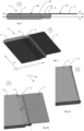
- Figs. 1 to 3b show schematic illustrations of an electronic device 2 comprising a display 15 and a foldable structure 1.
- the foldable structure 1 comprises a first body 3, the second body 4, and the third body 5 which are configured to support the display 15 and, optionally, additional components of the electronic device 2.
- Display 15 may be fixedly connected to the first body 3 and the second body 4 of the foldable structure 1, i.e., not to the third body 5 such that movement of the third body 5 is not restricted in any way by the display 15.
- the foldable structure 1 may be in a folded position P2 and an unfolded position P1, the display having a larger visible area when the foldable structure 1 is in the unfolded position P1.
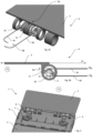
- Figs. 4a to 6 show the foldable structure 1 in more detail.
- the foldable structure 1 comprises a first body 3, a second body 4, a third body 5, and at least one hinge assembly 6.
- the third body 5 is operably connected to the first body 3 and the second body 4.
- the hinge assembly 6 is configured to allow the first body 3 to be rotated around a rotation axis A with respect to the third body 5.
- the hinge assembly 6 comprises an engagement structure and an actuator 9 which is connected to the first body 3 and the engagement structure.
- the engagement structure comprises a first engagement element 7 which is pivotally connected to the third body 5, and which is configured to pivot in a plane L1 parallel with the rotation axis A in response to rotation of the actuator 9 around the rotation axis A.
- the engagement structure also comprises a second engagement element 8 arranged on the second body 4, preferably stationarily.
- the first engagement element 7 engages the second engagement element, to a varying degree and/or at varying locations, as the first engagement element 7 pivots in plane L1.
- first engagement element 7 and the second engagement element 8 may comprise meshing teeth facilitating the sliding movement, forming a rack-and-pinion structure.
- the engagement structure may, e.g., comprise a worm gear.
- the actuator 9 is fixed to the first body 3 such that the actuator 9, as shown in Figs. 4a to 6 , rotates simultaneously with the first body 3 around the rotation axis A.
- the actuator 9 may comprise at least one of a chain, a wire, a rack, and a sheet.
- the actuator 9, as shown in Figs. 4a to 6 comprises a first section 9a which is fixed to the first body 3 such that at least the first section 9a of the actuator 9 rotates with the first body 3 around the rotation axis A.
- the actuator 9 also comprises a second section 9b fixed to the first engagement element 7 such that at least the second section 9b of the actuator 9 rotates in the plane L1, simultaneously with the rotation around the rotation axis A.
- the actuator 9 may also comprise a third section 9c which extends in a first actuation plane L2 and a fourth section 9d which extends in a second actuation plane L3, as shown in Fig. 4b .
- the first actuation plane L2 and the second actuation plane L3 extend in parallel with the plane L1 and on opposites sides of the rotation axis A.
- the third section 9c and the fourth section 9d may be arranged between the first section 9a and the second section 9b of the actuator 9.
- the third section 9c and the fourth section 9d may be connected to the second section 9b of the actuator at different heights relative the rotation axis A, and also at opposite sides of the pivot axis (not shown) around which the first engagement element 7 pivots.
- the third section 9c may move in the first actuation plane L2 and the fourth section 9d may move in the second actuation plane L3 in response to the first section 9a rotating around the rotation axis A.
- the third section 9c and the fourth section 9d move simultaneously and/or in opposite directions.
- the third section 9c may move in a direction perpendicular to and towards the rotation axis A, while the fourth section 9d moves in a direction perpendicular to and away from the rotation axis A.
- the third section 9c may move in a direction perpendicular to and away from the rotation axis A, while the fourth section 9d moves in a direction perpendicular to and towards the rotation axis A.
- the third body 5 may be at least partially enclosed by the second body 4. This allows the movement of the third body 5 to be steered and maintained in plane L1. Nevertheless, third body 5 may extend on top of or below the second body 4.
- a first surface 3a of the first body 3 and a first surface 4a of the second body 4 may be aligned in a common plane L4 when the foldable structure 1 is in the unfolded position P1, providing support for the display 15 of the electronic device 2.
- the second body 4 may be superimposed onto the first body 3 when the foldable structure 1 is in the folded position P2, allowing the outer dimensions of the electronic device 2 to be as small as possible, e.g., when not in use.
- a distance D between the first body 3 and the second body 4 may be at a minimum when the foldable structure 1 is in the folded position P2, and the very same distance D may be at a maximum when the foldable structure 1 is in the unfolded position P1.
- the overlap between the second body 4 and the third body 5 may be at a maximum when the foldable structure 1 is in the folded position P2, and the overlap may be at a minimum when the foldable structure 1 is in the unfolded position P1.
- the first surface 5a of the third body 5 may extend adjacent and parallel with the common plane L4 when the foldable structure 1 is in the unfolded position P1, such that there is an as small deviation as possible between first surface 5a and first surfaces 3a, 4a.
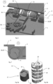
- the first section 9a of the actuator 9 may be fixed to the first body 3 by means of one or several shaft elements 10 extending within one or several sections 11 of the first body 3.
- Section 11 may be a substantially hollow cylinder, the shaft element 10 extending therein such that the shaft element 10 and the section 11 are colinear.
- the foldable structure 1 comprises two shaft elements 10 arranged at a distance from each other along the rotation axis A.
- Section 11 may be part of the first body 3 or attached thereto.
- the foldable structure 1 may also comprise a locking arrangement 12 configured to maintain the foldable structure 1 in at least one of the folded position P2 and the unfolded position P1.
- the locking and releasing of the locking arrangement 12 may be executed by means of an increase in the force applied onto the first body 3 and/or the second body 4 to rotate the first body 3 around the rotation axis A.
- the locking arrangement 12 may comprise a spring mechanism 16.
- the locking arrangement 12 may also comprise a first cam surface 13 and a second cam surface 14, the first cam surface 13 being arranged on a surface of the shaft element 10, as shown in Fig. 8b , or on a surface of the first body 3.
- the second cam surface 14 may be arranged on a separate cam element 17, as shown in Fig. 8a , connected to the third body 5.
- the first cam surface 13 and the second cam surface 14 may be configured to interlock when the foldable structure 1 is in at least one of the folded position P2 and the unfolded position P1, such that an increase in force is required, by the user, when moving the foldable structure 1, i.e.
- the first cam surface 13 and the second cam surface 14 are preferably arranged on short ends of shaft element 10, first body 3, or cam element 17.
- the locking arrangement 12 may furthermore comprise at least one groove 18 extending along a longitudinal surface of shaft element 10 and/or cam element 17, the groove(s) 18 being configured to interlock with corresponding ridges 19, such that the cam element 17 rotates along with the third body 5 and shaft element 10 rotates along with the first body 3.
- the foldable structure 1 may be fully user-operated, i.e., actuated in response to a user manually folding and unfolding the structure.
- the foldable structure 1 may also comprise a motor (not shown) configured to rotate the first body 3 around the rotation axis A, subsequently leading to actuation of the remainder of the foldable structure 1.
- inwardly and outwardly generally refer to the orientation of a surface relative to its axis of elongation, or axis of rotation, as appropriate.
Landscapes
- Engineering & Computer Science (AREA)
- Signal Processing (AREA)
- Telephone Set Structure (AREA)
Claims (14)
- Faltbare Struktur (1) für eine elektronische Vorrichtung (2), wobei die faltbare Struktur (1) Folgendes umfasst:einen ersten Körper (3);einen zweiten Körper (4);einen dritten Körper (5), der betriebsmäßig mit dem ersten Körper (3) und dem zweiten Körper (4) verbunden ist; undmindestens eine Scharnierbaugruppe (6), wobei der erste Körper (3) dazu konfiguriert ist, sich durch die eine Scharnierbaugruppe in Bezug auf den dritten Körper (5) um eine Drehachse (A) zu drehen,wobei die Scharnierbaugruppe (6) eine Eingriffsstruktur und einen Aktor (9) umfasst, der mit dem ersten Körper (3) und der Eingriffsstruktur verbunden ist,wobei der Aktor (9) an dem ersten Körper (3) befestigt ist und der Aktor (9) dazu ausgelegt ist, sich gleichzeitig mit dem ersten Körper (3) um die Drehachse (A) zu drehen,wobei die Eingriffsstruktur ein erstes Eingriffselement (7) umfasst, das schwenkbar mit dem dritten Körper (5) verbunden und dazu konfiguriert ist, als Reaktion auf die Drehung des Aktors (9) um die Drehachse (A) in einer Ebene (L1) parallel zu der Drehachse (A) zu schwenken, undein zweites Eingriffselement (8), das an dem zweiten Körper (4) angeordnet ist,wobei die Schwenkbewegung des ersten Eingriffselements (7) dazu ausgelegt ist, eine Gleitbewegung des zweiten Körpers (4) in Bezug auf den dritten Körper (5) in der Ebene (L1) zu erzeugen, wenn das erste Eingriffselement (7) mit dem zweiten Eingriffselement (8) in Eingriff kommt; undwobei der Aktor (9) Folgendes umfasst:einen ersten Abschnitt (9a), der an dem ersten Körper (3) befestigt ist, wobei der mindestens eine erste Abschnitt (9a) des Aktors (9) dazu ausgelegt ist, sich mit dem ersten Körper (3) um die Drehachse (A) zu drehen, undeinen zweiten Abschnitt (9b), der an dem ersten Eingriffselement (7) befestigt ist, wobei der mindestens eine zweite Abschnitt (9b) des Aktors (9) dazu ausgelegt ist, sich in der Ebene (L1) gleichzeitig mit der Drehung um die Drehachse (A) zu drehen, wobei die Drehung in der Ebene (L1) die Schwenkbewegung des ersten Eingriffselements (7) erzeugt.
- Faltbare Struktur (1) nach Anspruch 1, wobei das erste Eingriffselement (7) und das zweite Eingriffselement (8) ineinandergreifende Zähne umfassen.
- Faltbare Struktur (1) nach Anspruch 1, wobei der Aktor (9) mindestens eines einer Kette, eines Drahtes, einer Zahnstange oder eines Bleches umfasst.
- Faltbare Struktur (1) nach Anspruch 1 oder 3, wobei sich mindestens ein dritter Abschnitt (9c) des Aktors (9) in einer ersten Betätigungsebene (L2) erstreckt und sich ein vierter Abschnitt (9d) des Aktors (9) in einer zweiten Betätigungsebene (L3) erstreckt, wobei sich die erste Betätigungsebene (L2) und die zweite Betätigungsebene (L3) parallel zu der Ebene (L1) und auf gegenüberliegenden Seiten der Drehachse (A) erstrecken, wobei der dritte Abschnitt (9c) dazu ausgelegt ist, sich in der ersten Betätigungsebene (L2) zu bewegen, und wobei der vierte Abschnitt (9d) dazu ausgelegt ist, sich als Reaktion auf die Drehung des ersten Abschnitts (9a) um die Drehachse (A) in der zweiten Betätigungsebene (L3) zu bewegen.
- Faltbare Struktur (1) nach Anspruch 4, wobei der dritte Abschnitt (9c) und der vierte Abschnitt (9d) dazu ausgelegt sind, sich in entgegengesetzte Richtungen zu bewegen.
- Faltbare Struktur (1) nach einem der vorhergehenden Ansprüche, wobei eine erste Oberfläche (3a) des ersten Körpers (3) und eine erste Oberfläche (4a) des zweiten Körpers (4) in einer gemeinsamen Ebene (L4) ausgerichtet sind, wenn sich die faltbare Struktur (1) in einer entfalteten Position (P1) befindet, und der zweite Körper (4) auf dem ersten Körper (3) aufliegt, wenn sich die faltbare Struktur (1) in einer gefalteten Position (P2) befindet.
- Faltbare Struktur (1) nach Anspruch 6, wobei ein Abstand (D) zwischen dem ersten Körper (3) und dem zweiten Körper (4) minimal ist, wenn sich die faltbare Struktur (1) in der gefalteten Position (P2) befindet, und der Abstand (D) maximal ist, wenn sich die faltbare Struktur (1) in der entfalteten Position (P1) befindet.
- Faltbare Struktur (1) nach einem der vorhergehenden Ansprüche, wobei der erste Abschnitt (9a) des Aktors (9) durch ein Wellenelement (10), das sich innerhalb eines Abschnitts (11) des ersten Körpers (3) erstreckt, an dem ersten Körper (3) befestigt ist.
- Faltbare Struktur (1) nach einem der Ansprüche 6 bis 8, ferner umfassend eine Verriegelungsanordnung (12), die dazu konfiguriert ist, die faltbare Struktur (1) in mindestens einer der gefalteten Position (P2) und der entfalteten Position (P1) zu halten, wobei die Verriegelungsanordnung (12) dazu ausgelegt ist, Verriegeln und Lösen auszuführen und den ersten Körper (3) durch eine Erhöhung der Kraft, die auf den ersten Körper (3) und/oder den zweiten Körper (4) ausgeübt wird, um die Drehachse (A) zu drehen.
- Faltbare Struktur (1) nach Anspruch 9, wobei die Verriegelungsanordnung (12) einen Federmechanismus umfasst.
- Faltbare Struktur (1) nach Anspruch 10, wobei die Verriegelungsanordnung (12) eine erste Nockenfläche (13) und eine zweite Nockenfläche (14) umfasst, wobei die erste Nockenfläche (13) auf einer Oberfläche des Wellenelements (10) oder auf einer Oberfläche des ersten Körpers (3) angeordnet ist, wobei die zweite Nockenfläche (14) auf einem Nockenelement angeordnet ist, das mit dem dritten Körper (5) verbunden ist, wobei die erste Nockenfläche (13) und die zweite Nockenfläche (14) dazu konfiguriert sind, ineinanderzugreifen, wenn sich die faltbare Struktur (1) in mindestens einer der gefalteten Position (P2) und der entfalteten Position (P1) befindet.
- Faltbare Struktur (1) nach einem der vorhergehenden Ansprüche, ferner umfassend einen Motor, der dazu konfiguriert ist, den ersten Körper (3) um die Drehachse (A) zu drehen.
- Elektronische Vorrichtung (2), umfassend die faltbare Struktur (1) nach einem der Ansprüche 1 bis 12 und eine Anzeige (15), wobei der erste Körper (3), der zweite Körper (4) und der dritte Körper (5) der faltbaren Struktur (1) dazu konfiguriert sind, die Anzeige (15) zu stützen.
- Elektronische Vorrichtung (2) nach Anspruch 13, wobei die Anzeige (15) fest mit dem ersten Körper (3) und dem zweiten Körper (4) der faltbaren Struktur (1) verbunden ist.
Applications Claiming Priority (1)
| Application Number | Priority Date | Filing Date | Title |
|---|---|---|---|
| PCT/EP2021/053173 WO2022171274A1 (en) | 2021-02-10 | 2021-02-10 | Foldable structure for electronic device |
Publications (2)
| Publication Number | Publication Date |
|---|---|
| EP4256775A1 EP4256775A1 (de) | 2023-10-11 |
| EP4256775B1 true EP4256775B1 (de) | 2024-08-21 |
Family
ID=74591991
Family Applications (1)
| Application Number | Title | Priority Date | Filing Date |
|---|---|---|---|
| EP21704764.6A Active EP4256775B1 (de) | 2021-02-10 | 2021-02-10 | Faltbare struktur für elektronische vorrichtung |
Country Status (3)
| Country | Link |
|---|---|
| EP (1) | EP4256775B1 (de) |
| CN (1) | CN116803070B (de) |
| WO (1) | WO2022171274A1 (de) |
Family Cites Families (6)
| Publication number | Priority date | Publication date | Assignee | Title |
|---|---|---|---|---|
| US20090122015A1 (en) * | 2007-11-13 | 2009-05-14 | Randolph Cary Demuynck | Mobile terminals having a movable keyboard and methods for operating the same |
| US8102675B2 (en) * | 2009-04-15 | 2012-01-24 | Nokia Corporation | Apparatus, method, and computer program for using a driver wheel to provide a plurality of housing configurations |
| KR101483030B1 (ko) * | 2009-04-30 | 2015-01-26 | 엘지전자 주식회사 | 이동 단말기 |
| US20130104342A1 (en) * | 2011-10-27 | 2013-05-02 | Sony Mobile Communications Japan, Inc. | Mobile terminal |
| WO2015030713A1 (en) * | 2013-08-26 | 2015-03-05 | Hewlett-Packard Development Company, L.P. | Display panel responsive key retraction |
| US10876337B2 (en) * | 2018-09-12 | 2020-12-29 | Compal Electronics, Inc. | Sliding hinge and electronic device having the same |
-
2021
- 2021-02-10 EP EP21704764.6A patent/EP4256775B1/de active Active
- 2021-02-10 CN CN202180090725.2A patent/CN116803070B/zh active Active
- 2021-02-10 WO PCT/EP2021/053173 patent/WO2022171274A1/en not_active Ceased
Also Published As
| Publication number | Publication date |
|---|---|
| CN116803070B (zh) | 2026-03-13 |
| EP4256775A1 (de) | 2023-10-11 |
| WO2022171274A1 (en) | 2022-08-18 |
| CN116803070A (zh) | 2023-09-22 |
Similar Documents
| Publication | Publication Date | Title |
|---|---|---|
| EP3739561B1 (de) | Bildschirmkörperstützvorrichtung und faltbare flexible anzeigevorrichtung | |
| JP7007490B2 (ja) | 折り畳み式支持装置及び折り畳み式フレキシブル表示装置 | |
| CN110675745B (zh) | 显示装置 | |
| US11134579B2 (en) | Hinge module and electronic device | |
| CN214507124U (zh) | 一种铰链及内折柔性屏移动终端 | |
| US7187554B2 (en) | Movable console device | |
| US20240040021A1 (en) | Hinge with lifting drive control function, and inward-folding flexible screen mobile terminal | |
| CN213655447U (zh) | 折叠机构以及内折柔性屏设备 | |
| US7440265B2 (en) | Variable-sized screen | |
| JP2023549725A (ja) | 支持構造体及び表示装置 | |
| US12432287B2 (en) | Foldable electronic device | |
| JP2023541989A (ja) | 車両用の伸縮自在な表示装置 | |
| CN210183680U (zh) | 铰链装置及电子装置 | |
| US20240044360A1 (en) | Novel hinge and inward-folding flexible screen mobile terminal | |
| EP4420935B1 (de) | Fahrzeug und faltbare anzeigevorrichtung zur verwendung darin | |
| EP4256775B1 (de) | Faltbare struktur für elektronische vorrichtung | |
| CN114542587B (zh) | 一种转轴装置 | |
| JP7658030B2 (ja) | 折畳み携帯型表示デバイス | |
| CN114885052A (zh) | 电子设备 | |
| US20250194028A1 (en) | Foldable electronic device | |
| CN116439494B (zh) | 一种桌面显示器支架的孔盖让位密封结构及多功能办公桌 | |
| CN116052536B (zh) | 一种显示模组和折叠显示装置 | |
| DE102021119399B4 (de) | Fahrzeugseitenspiegelvorrichtung | |
| EP4029228B1 (de) | Gleitende anzeigevorrichtung für eine klappbare elektronische vorrichtung | |
| CN219856985U (zh) | 一种后视镜及汽车 |
Legal Events
| Date | Code | Title | Description |
|---|---|---|---|
| STAA | Information on the status of an ep patent application or granted ep patent |
Free format text: STATUS: UNKNOWN |
|
| STAA | Information on the status of an ep patent application or granted ep patent |
Free format text: STATUS: THE INTERNATIONAL PUBLICATION HAS BEEN MADE |
|
| PUAI | Public reference made under article 153(3) epc to a published international application that has entered the european phase |
Free format text: ORIGINAL CODE: 0009012 |
|
| STAA | Information on the status of an ep patent application or granted ep patent |
Free format text: STATUS: REQUEST FOR EXAMINATION WAS MADE |
|
| 17P | Request for examination filed |
Effective date: 20230706 |
|
| AK | Designated contracting states |
Kind code of ref document: A1 Designated state(s): AL AT BE BG CH CY CZ DE DK EE ES FI FR GB GR HR HU IE IS IT LI LT LU LV MC MK MT NL NO PL PT RO RS SE SI SK SM TR |
|
| GRAP | Despatch of communication of intention to grant a patent |
Free format text: ORIGINAL CODE: EPIDOSNIGR1 |
|
| STAA | Information on the status of an ep patent application or granted ep patent |
Free format text: STATUS: GRANT OF PATENT IS INTENDED |
|
| INTG | Intention to grant announced |
Effective date: 20240404 |
|
| DAV | Request for validation of the european patent (deleted) | ||
| DAX | Request for extension of the european patent (deleted) | ||
| GRAS | Grant fee paid |
Free format text: ORIGINAL CODE: EPIDOSNIGR3 |
|
| GRAA | (expected) grant |
Free format text: ORIGINAL CODE: 0009210 |
|
| STAA | Information on the status of an ep patent application or granted ep patent |
Free format text: STATUS: THE PATENT HAS BEEN GRANTED |
|
| P01 | Opt-out of the competence of the unified patent court (upc) registered |
Free format text: CASE NUMBER: APP_36971/2024 Effective date: 20240620 |
|
| AK | Designated contracting states |
Kind code of ref document: B1 Designated state(s): AL AT BE BG CH CY CZ DE DK EE ES FI FR GB GR HR HU IE IS IT LI LT LU LV MC MK MT NL NO PL PT RO RS SE SI SK SM TR |
|
| REG | Reference to a national code |
Ref country code: GB Ref legal event code: FG4D |
|
| REG | Reference to a national code |
Ref country code: CH Ref legal event code: EP |
|
| REG | Reference to a national code |
Ref country code: IE Ref legal event code: FG4D |
|
| REG | Reference to a national code |
Ref country code: DE Ref legal event code: R096 Ref document number: 602021017497 Country of ref document: DE |
|
| REG | Reference to a national code |
Ref country code: LT Ref legal event code: MG9D |
|
| REG | Reference to a national code |
Ref country code: NL Ref legal event code: MP Effective date: 20240821 |
|
| PG25 | Lapsed in a contracting state [announced via postgrant information from national office to epo] |
Ref country code: NO Free format text: LAPSE BECAUSE OF FAILURE TO SUBMIT A TRANSLATION OF THE DESCRIPTION OR TO PAY THE FEE WITHIN THE PRESCRIBED TIME-LIMIT Effective date: 20241121 |
|
| REG | Reference to a national code |
Ref country code: AT Ref legal event code: MK05 Ref document number: 1716694 Country of ref document: AT Kind code of ref document: T Effective date: 20240821 |
|
| PG25 | Lapsed in a contracting state [announced via postgrant information from national office to epo] |
Ref country code: PL Free format text: LAPSE BECAUSE OF FAILURE TO SUBMIT A TRANSLATION OF THE DESCRIPTION OR TO PAY THE FEE WITHIN THE PRESCRIBED TIME-LIMIT Effective date: 20240821 Ref country code: NL Free format text: LAPSE BECAUSE OF FAILURE TO SUBMIT A TRANSLATION OF THE DESCRIPTION OR TO PAY THE FEE WITHIN THE PRESCRIBED TIME-LIMIT Effective date: 20240821 Ref country code: GR Free format text: LAPSE BECAUSE OF FAILURE TO SUBMIT A TRANSLATION OF THE DESCRIPTION OR TO PAY THE FEE WITHIN THE PRESCRIBED TIME-LIMIT Effective date: 20241122 Ref country code: FI Free format text: LAPSE BECAUSE OF FAILURE TO SUBMIT A TRANSLATION OF THE DESCRIPTION OR TO PAY THE FEE WITHIN THE PRESCRIBED TIME-LIMIT Effective date: 20240821 Ref country code: PT Free format text: LAPSE BECAUSE OF FAILURE TO SUBMIT A TRANSLATION OF THE DESCRIPTION OR TO PAY THE FEE WITHIN THE PRESCRIBED TIME-LIMIT Effective date: 20241223 |
|
| PG25 | Lapsed in a contracting state [announced via postgrant information from national office to epo] |
Ref country code: BG Free format text: LAPSE BECAUSE OF FAILURE TO SUBMIT A TRANSLATION OF THE DESCRIPTION OR TO PAY THE FEE WITHIN THE PRESCRIBED TIME-LIMIT Effective date: 20240821 |
|
| PG25 | Lapsed in a contracting state [announced via postgrant information from national office to epo] |
Ref country code: LV Free format text: LAPSE BECAUSE OF FAILURE TO SUBMIT A TRANSLATION OF THE DESCRIPTION OR TO PAY THE FEE WITHIN THE PRESCRIBED TIME-LIMIT Effective date: 20240821 |
|
| PG25 | Lapsed in a contracting state [announced via postgrant information from national office to epo] |
Ref country code: AT Free format text: LAPSE BECAUSE OF FAILURE TO SUBMIT A TRANSLATION OF THE DESCRIPTION OR TO PAY THE FEE WITHIN THE PRESCRIBED TIME-LIMIT Effective date: 20240821 Ref country code: IS Free format text: LAPSE BECAUSE OF FAILURE TO SUBMIT A TRANSLATION OF THE DESCRIPTION OR TO PAY THE FEE WITHIN THE PRESCRIBED TIME-LIMIT Effective date: 20241221 |
|
| PG25 | Lapsed in a contracting state [announced via postgrant information from national office to epo] |
Ref country code: HR Free format text: LAPSE BECAUSE OF FAILURE TO SUBMIT A TRANSLATION OF THE DESCRIPTION OR TO PAY THE FEE WITHIN THE PRESCRIBED TIME-LIMIT Effective date: 20240821 |
|
| PG25 | Lapsed in a contracting state [announced via postgrant information from national office to epo] |
Ref country code: RS Free format text: LAPSE BECAUSE OF FAILURE TO SUBMIT A TRANSLATION OF THE DESCRIPTION OR TO PAY THE FEE WITHIN THE PRESCRIBED TIME-LIMIT Effective date: 20241121 Ref country code: ES Free format text: LAPSE BECAUSE OF FAILURE TO SUBMIT A TRANSLATION OF THE DESCRIPTION OR TO PAY THE FEE WITHIN THE PRESCRIBED TIME-LIMIT Effective date: 20240821 |
|
| PG25 | Lapsed in a contracting state [announced via postgrant information from national office to epo] |
Ref country code: RS Free format text: LAPSE BECAUSE OF FAILURE TO SUBMIT A TRANSLATION OF THE DESCRIPTION OR TO PAY THE FEE WITHIN THE PRESCRIBED TIME-LIMIT Effective date: 20241121 Ref country code: PT Free format text: LAPSE BECAUSE OF FAILURE TO SUBMIT A TRANSLATION OF THE DESCRIPTION OR TO PAY THE FEE WITHIN THE PRESCRIBED TIME-LIMIT Effective date: 20241223 Ref country code: PL Free format text: LAPSE BECAUSE OF FAILURE TO SUBMIT A TRANSLATION OF THE DESCRIPTION OR TO PAY THE FEE WITHIN THE PRESCRIBED TIME-LIMIT Effective date: 20240821 Ref country code: NO Free format text: LAPSE BECAUSE OF FAILURE TO SUBMIT A TRANSLATION OF THE DESCRIPTION OR TO PAY THE FEE WITHIN THE PRESCRIBED TIME-LIMIT Effective date: 20241121 Ref country code: NL Free format text: LAPSE BECAUSE OF FAILURE TO SUBMIT A TRANSLATION OF THE DESCRIPTION OR TO PAY THE FEE WITHIN THE PRESCRIBED TIME-LIMIT Effective date: 20240821 Ref country code: LV Free format text: LAPSE BECAUSE OF FAILURE TO SUBMIT A TRANSLATION OF THE DESCRIPTION OR TO PAY THE FEE WITHIN THE PRESCRIBED TIME-LIMIT Effective date: 20240821 Ref country code: IS Free format text: LAPSE BECAUSE OF FAILURE TO SUBMIT A TRANSLATION OF THE DESCRIPTION OR TO PAY THE FEE WITHIN THE PRESCRIBED TIME-LIMIT Effective date: 20241221 Ref country code: HR Free format text: LAPSE BECAUSE OF FAILURE TO SUBMIT A TRANSLATION OF THE DESCRIPTION OR TO PAY THE FEE WITHIN THE PRESCRIBED TIME-LIMIT Effective date: 20240821 Ref country code: GR Free format text: LAPSE BECAUSE OF FAILURE TO SUBMIT A TRANSLATION OF THE DESCRIPTION OR TO PAY THE FEE WITHIN THE PRESCRIBED TIME-LIMIT Effective date: 20241122 Ref country code: FI Free format text: LAPSE BECAUSE OF FAILURE TO SUBMIT A TRANSLATION OF THE DESCRIPTION OR TO PAY THE FEE WITHIN THE PRESCRIBED TIME-LIMIT Effective date: 20240821 Ref country code: ES Free format text: LAPSE BECAUSE OF FAILURE TO SUBMIT A TRANSLATION OF THE DESCRIPTION OR TO PAY THE FEE WITHIN THE PRESCRIBED TIME-LIMIT Effective date: 20240821 Ref country code: BG Free format text: LAPSE BECAUSE OF FAILURE TO SUBMIT A TRANSLATION OF THE DESCRIPTION OR TO PAY THE FEE WITHIN THE PRESCRIBED TIME-LIMIT Effective date: 20240821 Ref country code: AT Free format text: LAPSE BECAUSE OF FAILURE TO SUBMIT A TRANSLATION OF THE DESCRIPTION OR TO PAY THE FEE WITHIN THE PRESCRIBED TIME-LIMIT Effective date: 20240821 |
|
| PG25 | Lapsed in a contracting state [announced via postgrant information from national office to epo] |
Ref country code: DK Free format text: LAPSE BECAUSE OF FAILURE TO SUBMIT A TRANSLATION OF THE DESCRIPTION OR TO PAY THE FEE WITHIN THE PRESCRIBED TIME-LIMIT Effective date: 20240821 Ref country code: SM Free format text: LAPSE BECAUSE OF FAILURE TO SUBMIT A TRANSLATION OF THE DESCRIPTION OR TO PAY THE FEE WITHIN THE PRESCRIBED TIME-LIMIT Effective date: 20240821 Ref country code: RO Free format text: LAPSE BECAUSE OF FAILURE TO SUBMIT A TRANSLATION OF THE DESCRIPTION OR TO PAY THE FEE WITHIN THE PRESCRIBED TIME-LIMIT Effective date: 20240821 |
|
| PG25 | Lapsed in a contracting state [announced via postgrant information from national office to epo] |
Ref country code: EE Free format text: LAPSE BECAUSE OF FAILURE TO SUBMIT A TRANSLATION OF THE DESCRIPTION OR TO PAY THE FEE WITHIN THE PRESCRIBED TIME-LIMIT Effective date: 20240821 |
|
| PG25 | Lapsed in a contracting state [announced via postgrant information from national office to epo] |
Ref country code: CZ Free format text: LAPSE BECAUSE OF FAILURE TO SUBMIT A TRANSLATION OF THE DESCRIPTION OR TO PAY THE FEE WITHIN THE PRESCRIBED TIME-LIMIT Effective date: 20240821 |
|
| PG25 | Lapsed in a contracting state [announced via postgrant information from national office to epo] |
Ref country code: SK Free format text: LAPSE BECAUSE OF FAILURE TO SUBMIT A TRANSLATION OF THE DESCRIPTION OR TO PAY THE FEE WITHIN THE PRESCRIBED TIME-LIMIT Effective date: 20240821 Ref country code: IT Free format text: LAPSE BECAUSE OF FAILURE TO SUBMIT A TRANSLATION OF THE DESCRIPTION OR TO PAY THE FEE WITHIN THE PRESCRIBED TIME-LIMIT Effective date: 20240821 |
|
| REG | Reference to a national code |
Ref country code: DE Ref legal event code: R097 Ref document number: 602021017497 Country of ref document: DE |
|
| PLBE | No opposition filed within time limit |
Free format text: ORIGINAL CODE: 0009261 |
|
| STAA | Information on the status of an ep patent application or granted ep patent |
Free format text: STATUS: NO OPPOSITION FILED WITHIN TIME LIMIT |
|
| 26N | No opposition filed |
Effective date: 20250522 |
|
| PG25 | Lapsed in a contracting state [announced via postgrant information from national office to epo] |
Ref country code: SE Free format text: LAPSE BECAUSE OF FAILURE TO SUBMIT A TRANSLATION OF THE DESCRIPTION OR TO PAY THE FEE WITHIN THE PRESCRIBED TIME-LIMIT Effective date: 20240821 |
|
| PG25 | Lapsed in a contracting state [announced via postgrant information from national office to epo] |
Ref country code: MC Free format text: LAPSE BECAUSE OF FAILURE TO SUBMIT A TRANSLATION OF THE DESCRIPTION OR TO PAY THE FEE WITHIN THE PRESCRIBED TIME-LIMIT Effective date: 20240821 |
|
| REG | Reference to a national code |
Ref country code: CH Ref legal event code: PL |
|
| PG25 | Lapsed in a contracting state [announced via postgrant information from national office to epo] |
Ref country code: LU Free format text: LAPSE BECAUSE OF NON-PAYMENT OF DUE FEES Effective date: 20250210 |
|
| PG25 | Lapsed in a contracting state [announced via postgrant information from national office to epo] |
Ref country code: CH Free format text: LAPSE BECAUSE OF NON-PAYMENT OF DUE FEES Effective date: 20250228 |
|
| REG | Reference to a national code |
Ref country code: BE Ref legal event code: MM Effective date: 20250228 |
|
| PG25 | Lapsed in a contracting state [announced via postgrant information from national office to epo] |
Ref country code: FR Free format text: LAPSE BECAUSE OF NON-PAYMENT OF DUE FEES Effective date: 20250228 |
|
| PG25 | Lapsed in a contracting state [announced via postgrant information from national office to epo] |
Ref country code: BE Free format text: LAPSE BECAUSE OF NON-PAYMENT OF DUE FEES Effective date: 20250228 |
|
| PG25 | Lapsed in a contracting state [announced via postgrant information from national office to epo] |
Ref country code: IE Free format text: LAPSE BECAUSE OF NON-PAYMENT OF DUE FEES Effective date: 20250210 |
|
| PGFP | Annual fee paid to national office [announced via postgrant information from national office to epo] |
Ref country code: GB Payment date: 20260106 Year of fee payment: 6 |
|
| PGFP | Annual fee paid to national office [announced via postgrant information from national office to epo] |
Ref country code: DE Payment date: 20251230 Year of fee payment: 6 |