EP4026305B9 - Scharnieranordnung zum kontrollierten zusammenklappen einer elektronischen vorrichtung - Google Patents
Scharnieranordnung zum kontrollierten zusammenklappen einer elektronischen vorrichtung Download PDFInfo
- Publication number
- EP4026305B9 EP4026305B9 EP19791242.1A EP19791242A EP4026305B9 EP 4026305 B9 EP4026305 B9 EP 4026305B9 EP 19791242 A EP19791242 A EP 19791242A EP 4026305 B9 EP4026305 B9 EP 4026305B9
- Authority
- EP
- European Patent Office
- Prior art keywords
- hinge
- hinge assembly
- section
- linear drive
- extending
- Prior art date
- Legal status (The legal status is an assumption and is not a legal conclusion. Google has not performed a legal analysis and makes no representation as to the accuracy of the status listed.)
- Active
Links
Images

Classifications
-
- H—ELECTRICITY
- H04—ELECTRIC COMMUNICATION TECHNIQUE
- H04M—TELEPHONIC COMMUNICATION
- H04M1/00—Substation equipment, e.g. for use by subscribers
- H04M1/02—Constructional features of telephone sets
- H04M1/0202—Portable telephone sets, e.g. cordless phones, mobile phones or bar type handsets
- H04M1/0206—Portable telephones comprising a plurality of mechanically joined movable body parts, e.g. hinged housings
- H04M1/0208—Portable telephones comprising a plurality of mechanically joined movable body parts, e.g. hinged housings characterized by the relative motions of the body parts
- H04M1/0214—Foldable telephones, i.e. with body parts pivoting to an open position around an axis parallel to the plane they define in closed position
- H04M1/0216—Foldable in one direction, i.e. using a one degree of freedom hinge
-
- H—ELECTRICITY
- H05—ELECTRIC TECHNIQUES NOT OTHERWISE PROVIDED FOR
- H05K—PRINTED CIRCUITS; CASINGS OR CONSTRUCTIONAL DETAILS OF ELECTRIC APPARATUS; MANUFACTURE OF ASSEMBLAGES OF ELECTRICAL COMPONENTS
- H05K5/00—Casings, cabinets or drawers for electric apparatus
- H05K5/02—Details
- H05K5/0217—Mechanical details of casings
- H05K5/0226—Hinges
-
- G—PHYSICS
- G06—COMPUTING OR CALCULATING; COUNTING
- G06F—ELECTRIC DIGITAL DATA PROCESSING
- G06F1/00—Details not covered by groups G06F3/00 - G06F13/00 and G06F21/00
- G06F1/16—Constructional details or arrangements
- G06F1/1613—Constructional details or arrangements for portable computers
- G06F1/1615—Constructional details or arrangements for portable computers with several enclosures having relative motions, each enclosure supporting at least one I/O or computing function
- G06F1/1616—Constructional details or arrangements for portable computers with several enclosures having relative motions, each enclosure supporting at least one I/O or computing function with folding flat displays, e.g. laptop computers or notebooks having a clamshell configuration, with body parts pivoting to an open position around an axis parallel to the plane they define in closed position
- G06F1/1618—Constructional details or arrangements for portable computers with several enclosures having relative motions, each enclosure supporting at least one I/O or computing function with folding flat displays, e.g. laptop computers or notebooks having a clamshell configuration, with body parts pivoting to an open position around an axis parallel to the plane they define in closed position the display being foldable up to the back of the other housing with a single degree of freedom, e.g. by 360° rotation over the axis defined by the rear edge of the base enclosure
-
- G—PHYSICS
- G06—COMPUTING OR CALCULATING; COUNTING
- G06F—ELECTRIC DIGITAL DATA PROCESSING
- G06F1/00—Details not covered by groups G06F3/00 - G06F13/00 and G06F21/00
- G06F1/16—Constructional details or arrangements
- G06F1/1613—Constructional details or arrangements for portable computers
- G06F1/1633—Constructional details or arrangements of portable computers not specific to the type of enclosures covered by groups G06F1/1615 - G06F1/1626
- G06F1/1637—Details related to the display arrangement, including those related to the mounting of the display in the housing
- G06F1/1652—Details related to the display arrangement, including those related to the mounting of the display in the housing the display being flexible, e.g. mimicking a sheet of paper, or rollable
-
- G—PHYSICS
- G06—COMPUTING OR CALCULATING; COUNTING
- G06F—ELECTRIC DIGITAL DATA PROCESSING
- G06F1/00—Details not covered by groups G06F3/00 - G06F13/00 and G06F21/00
- G06F1/16—Constructional details or arrangements
- G06F1/1613—Constructional details or arrangements for portable computers
- G06F1/1633—Constructional details or arrangements of portable computers not specific to the type of enclosures covered by groups G06F1/1615 - G06F1/1626
- G06F1/1675—Miscellaneous details related to the relative movement between the different enclosures or enclosure parts
- G06F1/1681—Details related solely to hinges
-
- H—ELECTRICITY
- H05—ELECTRIC TECHNIQUES NOT OTHERWISE PROVIDED FOR
- H05K—PRINTED CIRCUITS; CASINGS OR CONSTRUCTIONAL DETAILS OF ELECTRIC APPARATUS; MANUFACTURE OF ASSEMBLAGES OF ELECTRICAL COMPONENTS
- H05K5/00—Casings, cabinets or drawers for electric apparatus
- H05K5/0017—Casings, cabinets or drawers for electric apparatus with operator interface units
- H05K5/0018—Casings, cabinets or drawers for electric apparatus with operator interface units having an electronic display
-
- E—FIXED CONSTRUCTIONS
- E05—LOCKS; KEYS; WINDOW OR DOOR FITTINGS; SAFES
- E05Y—INDEXING SCHEME ASSOCIATED WITH SUBCLASSES E05D AND E05F, RELATING TO CONSTRUCTION ELEMENTS, ELECTRIC CONTROL, POWER SUPPLY, POWER SIGNAL OR TRANSMISSION, USER INTERFACES, MOUNTING OR COUPLING, DETAILS, ACCESSORIES, AUXILIARY OPERATIONS NOT OTHERWISE PROVIDED FOR, APPLICATION THEREOF
- E05Y2999/00—Subject-matter not otherwise provided for in this subclass
-
- G—PHYSICS
- G06—COMPUTING OR CALCULATING; COUNTING
- G06F—ELECTRIC DIGITAL DATA PROCESSING
- G06F2203/00—Indexing scheme relating to G06F3/00 - G06F3/048
- G06F2203/041—Indexing scheme relating to G06F3/041 - G06F3/045
- G06F2203/04102—Flexible digitiser, i.e. constructional details for allowing the whole digitising part of a device to be flexed or rolled like a sheet of paper
-
- H—ELECTRICITY
- H04—ELECTRIC COMMUNICATION TECHNIQUE
- H04M—TELEPHONIC COMMUNICATION
- H04M1/00—Substation equipment, e.g. for use by subscribers
- H04M1/02—Constructional features of telephone sets
- H04M1/0202—Portable telephone sets, e.g. cordless phones, mobile phones or bar type handsets
- H04M1/0206—Portable telephones comprising a plurality of mechanically joined movable body parts, e.g. hinged housings
- H04M1/0208—Portable telephones comprising a plurality of mechanically joined movable body parts, e.g. hinged housings characterized by the relative motions of the body parts
- H04M1/0214—Foldable telephones, i.e. with body parts pivoting to an open position around an axis parallel to the plane they define in closed position
- H04M1/0216—Foldable in one direction, i.e. using a one degree of freedom hinge
- H04M1/022—The hinge comprising two parallel pivoting axes
-
- H—ELECTRICITY
- H04—ELECTRIC COMMUNICATION TECHNIQUE
- H04M—TELEPHONIC COMMUNICATION
- H04M1/00—Substation equipment, e.g. for use by subscribers
- H04M1/02—Constructional features of telephone sets
- H04M1/0202—Portable telephone sets, e.g. cordless phones, mobile phones or bar type handsets
- H04M1/026—Details of the structure or mounting of specific components
- H04M1/0266—Details of the structure or mounting of specific components for a display module assembly
- H04M1/0268—Details of the structure or mounting of specific components for a display module assembly including a flexible display panel
Definitions
- the disclosure relates to a hinge assembly for an electronic device, the hinge assembly being moveable between an unfolded position and at least a first folded end position, and comprising at least one linear actuator.
- the size of electronic devices is an important consideration when designing electronic devices.
- the user oftentimes requests the outer dimensions of the device to be as small as possible while still providing a display which is as large as possible.
- This problem may be solved, e.g., by means of a foldable electronic device comprising one or several support bodies, e.g. interconnected by means of hinges, covered by a display.
- the support body/bodies and the display can be folded together to provide an as small electronic device as possible, and unfolded to provide an as large display as possible.
- One solution is to provide the electronic device with a resilient connection between the display and the support body, the resilient connection taking up any stretching and compression.
- the resilient connection and the configuration of the hinges still affects the appearance of the display, leaving the surface of the display uneven.
- Document US 10 209 743 B1 relates to a flexible display device which includes a base support, a flexible display, and at least one positioning mechanism.
- the base support includes a first support plate extending lengthwise to terminate at a left end and a right end, a second support plate extending lengthwise to terminate at a left end and a right end, and a support rib unit including a plurality of support ribs which are juxtaposed to each other, and which are configured to be associated with each other to permit the support rib unit to be structurally flexible.
- the support rib unit is flanked by and configured to loosely interconnect the first and second support plates so as to permit the base support to be structurally flexible between a normal position and a bent position.
- Each of the support ribs extends lengthwise to terminate at a left end and a right end.
- the flexible display is supported by the base support to be bendable with the base support.
- the positioning mechanism is disposed leftward or rightward of the base support, and which includes a first mount, a second mount, a plurality of hinge bodies, a leaf spring unit, a sliding block, and a spring-loaded unit.
- the first mount is mounted to a corresponding one of the left and right ends of the first support plate to permit the first mount to move with the first support plate, and includes a camming wall with a camming surface, and an abutment wall that is spaced apart from the camming wall to define a first cavity.
- the second mount is mounted to a corresponding one of the left and right ends of the second support plate to permit the second mount to move with the second support plate, and defines therein a second cavity.
- the hinge bodies are chained to each other along a chain line.
- Each of the hinge bodies has a through bore and is configured to be in interference engagement with a corresponding one of the left and right ends of the respective support rib so as to permit the hinge bodies to be structurally flexible with the support rib unit.
- the through bores of the hinge bodies are arranged in tandem along the chain line.
- Each of the hinge bodies has a cover wall, and a base wall which is spaced apart from the cover wall to define the through bore, and which has a floor segment and an elevated cantilever segment.
- the base wall is configured to permit the elevated cantilever segment of one of the hinge bodies to overlie and to slidably engage with the floor segment of an adjacent one of the hinge bodies.
- the leaf spring unit extends along the chain line to pass through the through bores of the hinge bodies to terminate at a first spring end which is to be disposed in the first cavity, and a second spring end secured in the second cavity.
- the sliding block is fitted in the first cavity, and is slidable from a distal position corresponding to the normal position, to a proximate position corresponding to the bent position.
- the sliding block has a retaining segment distal from the second mount, and a securing segment which is proximate to the second mount, and which is configured to secure the first spring end thereto.
- the retaining segment has a first segment wall and a second segment wall.
- the first segment wall confronts the camming wall, and has a first opening.
- the second segment wall confronts the abutment wall, and is spaced apart from the first segment wall to define an accommodation space.
- the spring-loaded unit is disposed in the accommodation space, and includes a pin stem and a biasing member.
- the pin stem is disposed in the accommodation space, and extends through the first opening to terminate at a first stem end.
- a hinge assembly for an electronic device, the hinge assembly being moveable between an unfolded position and at least a first folded end position, the hinge assembly comprising a row of interconnected and abutting hinge blades and at least one linear actuator, the hinge blades being aligned in a common plane when the hinge assembly is in the unfolded position, each hinge blade being rotated relative to neighboring hinge blades around a first hinge assembly rotation axis, when the hinge assembly is moved to the first folded end position, the linear actuator comprising a rotation shaft and a plurality of linear drive arrangements having different lengths, the rotation shaft extending in parallel with the first hinge assembly rotation axis and comprising sections having different diameters, a first end of each linear drive arrangement being interconnected with a section of the rotation shaft having one diameter, a second, opposite end of each linear drive arrangement being connected to one hinge blade, an actuator axis extending between the first and second ends of each linear drive arrangement and perpendicular to the first hinge assembly rotation axis, wherein
- Such a solution allows for a hinge assembly which has as small outer dimensions as possible, while having a range of motion which allows, e.g., two components interconnected by the hinge assembly, such as two electronic device frame sections, to be moved between an unfolded position, in which the frame sections extend to provide a maximum electronic device width, and a folded position in which the two sections are superimposed onto each other such that they extend to provide only a minimum electronic device width.
- the solution provides support to any components which extend the two interconnected components across the hinge assembly.
- each hinge blade has its own manufacturing and rotation tolerance, however, with this solution the different tolerances do not stack up and hence, the impact on the display is minimized.
- rotation of the neighboring hinge blades is initiated successively in response to the differing diameters of the rotation shaft.
- Such a solution allows rotation of neighboring hinge blades to be initiated successively in response to the differing diameters of the linear drive arrangements. The smaller the diameter, the less the linear drive arrangement will move and the less the hinge blade will rotate. Hence, the desired turning profile is set for each hinge blade.
- the hinge assembly comprises at least a first linear actuator and a second linear actuator, the first linear actuator comprising a first rotation shaft and plurality of first linear drive arrangements, the second linear actuator comprising a second rotation shaft and plurality of second linear drive arrangements, the first rotation shaft and the second rotation shaft extending in parallel, the first linear drive arrangements and the second linear drive arrangements extending in parallel.
- one of the first linear drive arrangements and one of the second linear drive arrangements are connected to the same hinge blade, synchronizing the actuation of the first linear actuator and the second linear actuator, keeping the movement of all rotation shafts and hinge blades synchronized.
- a first dimension of a first outer surface of the hinge assembly is larger than a corresponding second dimension of a second outer surface of the hinge assembly when the hinge assembly is in the first folded end position, the first linear actuator and/or the second linear actuator being actuated by a difference between the first dimension and the second dimension.
- the linear drive arrangement comprises a chain or a wire.
- the hinge assembly comprises a neutral axis, a first end of the linear drive arrangement engaging the rotation shaft, and a second end of the linear drive arrangement engaging a first location and a second location of an individual hinge blade, the first location and the second location being located on opposite sides of, and with equidistant spacing from, the neutral axis, the linear drive arrangement extending through any hinge blades located in a first area between the individual hinge blade and the rotation shaft, the linear drive arrangement comprising a first section and a second section extending on opposite sides of, and with equidistant spacing from, the neutral axis, a first rotation of the rotation shaft rotating the linear drive arrangement in a first direction, and a second rotation of the rotation shaft rotating the linear drive arrangement in a second direction.
- the movement generated by the linear actuator is synchronized on both sides of the neutral axis.
- the linear drive arrangement comprises a wire partially wound around the rotation shaft, providing a secure, simple, and reliable linear actuation.
- the hinge assembly comprises a neutral axis
- the linear drive arrangement comprises a first section and a second section extending through an individual hinge blade and engaging the rotation shaft at a first end of the linear drive arrangement, the first section and the second section extending partially on opposite sides of, and with equidistant spacing from, the neutral axis, the first section extending in a first area between the first end and the individual hinge blade, on a first side of the neutral axis, and the second section extending in the first area on a second side of the neutral axis, the first section and the second section furthermore engaging the individual hinge blade by extending through the individual hinge blade such that the first section extends from the first side of the neutral axis to the second side of the neutral axis, and the second section extends from the second side of the neutral axis to the first side of the neutral axis, the first section extending, in a second area between the individual hinge blade and a second end of the linear drive arrangement, on the first side
- the first section and the second section furthermore engage a second individual hinge blade by extending through the second individual hinge blade such that the first section extends back from the second side of the neutral axis to the first side of the neutral axis, and the second section extends back from the first side of the neutral axis to the second side of the neutral axis, the first section extending, in a third area between the second individual hinge blade and the second end of the linear drive arrangement, on the first side of the neutral axis, and the second section extending, in the third area, on the second side of the neutral axis, allowing any hinge blades located in the third area to be pivoted in the opposite, second direction around a third hinge assembly rotation axis extending in parallel with the first hinge assembly rotation axis.
- an electronic device comprising a first frame section, a second frame section, a display connected to at least one of the first frame section and the second frame section, and a hinge assembly according to the above interconnecting the first frame section and the second frame section such that the first frame section and the second frame section are pivotable, relative each other, between an unfolded position and a first folded end position, the first frame section and the second frame section being aligned in a common plane when in the unfolded position, the second frame section being superimposed on the first frame section when in the first folded end position.
- each hinge blade of the hinge assembly has its own manufacturing and rotation tolerances, which tolerances do not stack up leaving the impact on the display minimal.
- the hinge assembly interconnects the first frame section and the second frame section such that the first frame section and the second frame section are pivotable, relative each other, between an unfolded position and a second folded end position, the first frame section being superimposed on the second frame section when in the second folded end position.
- Figs. 10a and 10b show an electronic device 14 comprising a first frame section 4, a second frame section 5, and a display 2 connected to at least one of the first frame section 4 and the second frame section 5.
- a hinge assembly 1 interconnects the first frame section 4 and the second frame section 5 such that the first frame section 4 and the second frame section 5 are pivotable, relative each other, between an unfolded position P1 and at least a first folded end position P2a around the first hinge assembly rotation axis A1a.
- the first frame section 4 and the second frame section 5 are also pivotable, relative each other, between an unfolded position P1 and a second folded end position P2b.
- the electronic device 14 is also folded from an unfolded position to a folded end position.
- the first frame section 4 and the second frame section 5 are aligned in a common plane when in the unfolded position P 1, as shown in the center drawings of Figs. 10a and 10b .
- the second frame section 5 is superimposed on top of the first frame section 4 when in the first folded end position P2a, as shown in the top drawings of Figs. 10a and 10b .
- the first frame section 4 is superimposed on top of the second frame section 5 when in the second folded end position P2b, as shown in the bottom drawings of Figs. 10a and 10b .
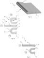
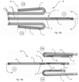
- Fig. 1a shows a simplified perspective view of an embodiment of the hinge assembly 1.
- the hinge assembly 1 is moveable between the unfolded position P1 and at least one folded end position, preferably between the unfolded position P1, a first folded end position P2a, and a second folded end position P2b.
- the hinge assembly 1 comprises a row of interconnected and abutting hinge blades 9 and at least one linear actuator 6, 7 .
- the hinge blades 9 are at least partially tapered and interconnected by means of an elongated connection element 10 extending along the actuator axis A2, as shown in Figs. 1b and 9b .
- the hinge blades 9 may be tapered in one direction, as shown in Fig. 1c , or in two directions, as shown in Fig. 1b .
- One-directional tapering allows the hinge assembly 1 to fold in only one direction, e.g. to first folded end position P2a, while bi-directional tapering allows the hinge assembly 1 to fold in two directions, i.e. to first folded end position P2a as well as second folded end position P2b.
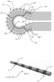
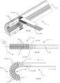
- Each linear actuator 6, 7 comprises a rotation shaft 12 and a plurality of linear drive arrangements 13 having different lengths 10, as shown in Figs. 2 to 6 .
- the rotation shaft 12 extends in parallel with the first hinge assembly rotation axis A1a and comprises a plurality of sections 3 having different diameters 11, as shown in Fig. 8 .
- the rotation shaft 12 may extend within the first frame section 4 or the second frame section 5, for ease of reading the rotation shaft 12 is shown as located within the second frame section 5 in the Figs. and in the text below.
- a first end 13a of each linear drive arrangement 13 is interconnected with one section 3 of the rotation shaft 12 having one diameter 11, and a second, opposite end of each linear drive arrangement 13 is connected to one hinge blade 9, as shown in Fig. 4 .
- the actuator axis A2 extends between the first and second ends 13b of the linear drive arrangement 13 and perpendicular to the first hinge assembly rotation axis A1a.
- the connection may be releasable or fixed using, e.g., adhesive or fasteners such as screws.
- the smallest diameter 11 on the rotation shaft 12 might be too small for the hinge blades 9 which rotate the least, i.e. the hinge blades 9 located nearest to the second frame section 5, and hence the rotation shaft 12, the smallest diameter 11 may be increased by providing two or more linear actuators 6, 7, i.e. a first rotation shaft 12a connected to a first plurality of linear drive arrangements 13 and a second rotation shaft 12b connected to a second plurality of linear drive arrangements 13.
- one linear drive arrangement 13 of the first linear actuator 6 and one linear drive arrangement 13 of the second linear actuator 7 are connected to the same hinge blade 9.
- first rotation shaft 12a and the second rotation shaft 12b extend in parallel, and the first linear drive arrangements 13 and the second linear drive arrangements 13 extend in parallel, as indicated by Fig. 6 .
- the hinge blades 9 are aligned in a common plane when the hinge assembly 1 is in the unfolded position P1, and each hinge blade 9 is rotated relative neighboring hinge blades 9 around the first hinge assembly rotation axis A1a, when the hinge assembly 1 is moved to the first folded end position P2a or to the second folded end position P2b.
- Actuation of the linear actuator 6, 7 along the actuator axis A2 may urge each hinge blade 9 to rotate relative neighboring hinge blades 9 around the first hinge assembly rotation axis A1a. Rotation of the neighboring hinge blades 9 is initiated successively in response to the differing diameters 11 of the linear drive arrangements 13. The smaller the diameter, the less the linear drive arrangement 13 will move, and the less the hinge blade 9 will rotate. Hence, the desired turning profile is set for each hinge blade 9.
- pivoting of the first frame section 4 and/or the second frame section 5 around the first hinge assembly rotation axis A1a actuates the first linear actuator 6 and the second linear actuator 7, such that one of the display 2 and the second frame section 5 are urged to move, in relation to the hinge assembly 1, along the actuator axis A2. Movement of the display 2 in relation to the hinge assembly 1 is shown in Fig. 10a . Movement of the second frame section 5 in relation to the hinge assembly 1 is shown in Fig. 10b .
- the hinge assembly 1 comprises a foldable back cover, the linear actuator 6 being connected to the display and the linear actuator 7 being connected to the back cover (not shown).
- the linear actuator 7 urges the back cover to move, in relation to the hinge assembly 1, along the actuator axis A2 but in a direction opposite to that of the display 2.
- the display 2 moves in a first direction and the back cover moves in an opposite, second direction along the actuator axis A2. This opposite movement is indicated in Fig. 9c by means of arrows.
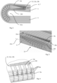
- a first dimension of a first outer surface 8a of the hinge assembly 1, i.e. the outer circumference of the folded hinge assembly 1, is larger than a corresponding second dimension of a second outer surface 8b of the pivot hinge 15 the inner circumference of the folded hinge assembly 1, when the hinge assembly 1 is in a folded end position, as shown in Fig. 9c .
- the linear actuator 6, 7 is actuated by the difference between the first dimension and the second dimension.
- the hinge assembly 1 is folded to end position P2a, the dimensions of the first outer surface 8a increases and the linear drive arrangement 13 is pulled in one direction, as is shown in the lowermost drawing of Figs. 1b , 10a, and 10b .
- the hinge assembly 1 is folded to the opposite end position P2b, the dimensions of the first outer surface 8a decreases and the linear drive arrangement 13 is pulled in the opposite direction, as is shown in the uppermost drawing of Figs. 1b , 10a, and 10b .
- the hinge assembly 1 comprises a neutral axis N as indicated in Fig. 1c .
- a first end 13a of the linear drive arrangements 13 engages the rotation shaft 12, and a second end 13b of each linear drive arrangement 13 engages a first location and a second location of an individual hinge blade 9a.
- the first location and the second location are located on opposite sides of, and with equidistant spacing from, the neutral axis N.
- Each linear drive arrangement 13 extends through any hinge blades 9b located in a first area between the individual hinge blade 9a and the rotation shaft 12.
- each linear drive arrangement 13 comprises a first section 13c and a second section 13d extending on opposite sides of, and with equidistant spacing from, the neutral axis N, see e.g. Figs. 3 and 5 .
- a first rotation of the rotation shaft 12 rotates the linear drive arrangements 13 in a first direction
- a second opposite rotation of the rotation shaft 12 rotates the linear drive arrangements 13 in a second opposite direction.
- the center axis of the rotation shaft 12 intersects the neutral axis N.
- the hinge assembly 1 comprises a neutral axis N
- the linear drive arrangements 13 comprise a first section 13c and a second section 13d extending through an individual hinge blade 9a and engaging the rotation shaft 12 at a first end 13a of the linear drive arrangement 13.
- the first section 13c and the second section 13d extend partially on opposite sides of, and with equidistant spacing from, the neutral axis N.
- the first section 13c extends in a first area between the first end 13a of the linear drive arrangement 13 and the individual hinge blade 9a, on a first side of the neutral axis N
- the second section 13d extends in the first area between the first end 13a of the linear drive arrangement 13 and the individual hinge blade 9a, on a second side of the neutral axis N, as indicated in Fig. 7 .
- the first section 13c and the second section 13d may furthermore engage the individual hinge blade 9a by extending through the individual hinge blade 9a such that the first section 13c extends from the first side of the neutral axis N to the second side of the neutral axis N, and the second section 13d extends from the second side of the neutral axis N to the first side of the neutral axis N, the first section 13c and the second section 13d effectively crossing each other in the area of the individual hinge blade 9a.
- the first section 13c may subsequently extend, in a second area between the individual hinge blade 9a and the second end 13b of the linear drive arrangement 13, on the second side of the neutral axis N, and the second section 13d extend, in the second area, on the first side of the neutral axis N between the individual hinge blade 9a and the second end 13b of the linear drive arrangement 13.
- the first section 13c and the second section 13d may furthermore engage a second individual hinge blade 9d and extend through the second individual hinge blade 9d such that the first section 13c extends back from the second side of the neutral axis N to the first side of the neutral axis N, and the second section 13d extends back from the first side of the neutral axis N to the second side of the neutral axis N, the first section 13c and the second section 13d effectively crossing each other in the area of the second individual hinge blade 9d.
- the first section 13c may thereafter extend, in a third area between the second individual hinge blade 9d and the second end 13b of the linear drive arrangement 13, on the first side of the neutral axis N, and the second section 13d extend, in the third area, on the second side of the neutral axis N between the second individual hinge blade 9d and the second end 13b of the linear drive arrangement 13.
- any hinge blades 9c located in the second area to be pivoted in a first direction around the first hinge assembly rotation axis A1a, and, simultaneously, allows any hinge blades 9b located in the first area to be pivoted in an opposite, second direction around a second hinge assembly rotation axis A1b, and any hinge blades 9e located in the third area to be pivoted in the opposite, second direction around a third hinge assembly rotation axis A1c, the second hinge assembly rotation axis A1b and the third hinge assembly rotation axis A1c both extending in parallel with the first hinge assembly rotation axis A1a.
- the linear drive arrangement 13 may comprise a chain (not shown) or a wire, as shown in Figs. 2 to 7 .
- the linear drive arrangement 13 When the linear drive arrangement 13 comprises a wire, it may be partially wound around the rotation shaft 12, as shown in Fig. 5 , and extend through the hinge assembly along the actuator axis A2. A first rotation of the rotation shaft 12 rotates the linear drive arrangement 13 in a first direction, and an opposite, second rotation of the rotation shaft 12 rotates the linear drive arrangement 13 in a second direction.
- the wire may comprise two separate wire sections 13a, 13b extending in parallel between the first frame section 4 and the second frame section 5, or the wire may comprise an uninterrupted loop.
- the linear drive arrangement 13 may furthermore comprise at least one chain, as shown in Figs. 9a to 9c .
- the linear drive arrangement 13 may comprise two separate chain sections extending in parallel between the first frame section 4 and the second frame section 5.
- the rotation shaft 12 comprises at least one pinion and the linear drive arrangement 13 furthermore comprises at least a first rack connected to the chain and engaging the pinion at a first location.
- a first rotation of the rotation shaft 12 and the pinion moves the rack in a first direction along the actuator axis A2, hence pulling the chain in the first direction, and an opposite, second rotation of the rotation shaft 12 and the pinion moves the rack in a second direction along the actuator axis A2, hence pushing the chain in the second direction.
- the linear drive arrangement 13 may further comprise a second rack connected to the chain and engaging the pinion at a second location opposite the first location and extending along the actuator axis A2.
- a first rotation of the rotation shaft 12 and the pinion simultaneously moves the first rack in the first direction and the second rack in the second direction, such that the first rack pulls the chain in the first direction and the second rack, simultaneously, pushes the chain in the first direction.
- An opposite, second rotation of the rotation shaft 12 and the pinion simultaneously moves the first rack in the second direction and the second rack in the first direction, such that the first rack pushes the chain in the second direction and the second rack, simultaneously, pulls the chain in the second direction.
- the first rack may be connected to the display 2 while the second rack is connected to the back cover, such that the display 2 and the back cover are moved simultaneously in opposite directions, along the actuator axis A2, when the linear actuator 6, 7 is actuated.
- the present disclosure also relates to an electronic device 14, shown in Figs. 10a and 10b , comprising the above described hinge assembly 1.
- the display 2 and/or the back cover of the electronic device are fixedly connected to the first frame section 4, and pivoting the first frame section 4 or the second frame section 5 will actuate the linear actuator 6, 7.
- the linear actuator 6, 7 urges the display 2 and/or the back cover to slide in relation to the hinge assembly 1 such that an overlap between the display 2 and/or the back cover and the second frame section 5 varies, as shown in, e.g., Fig. 10a .
- the overlap between the display 2 and the second frame section 5 is at a minimum when the hinge assembly 1 is in the first folded end position P2a.
- the overlap between the display 2 and the second frame section 5 is at a maximum when the hinge assembly 1 is in the second folded end position P2b.
- the display 2 or the back cover is fixedly connected to the first frame section 4 and second frame section 5.
- the hinge assembly 1 comprises sliding rails interconnecting the hinge assembly 1 and the second frame section 5, and pivoting the first frame section 4 or the second frame section 5 actuates the linear actuator 6, 7.
- the linear actuator 6, 7 urges the second frame section 5 to slide, on the sliding rails 11, in relation to the hinge assembly such that the distance between the hinge assembly 1 and the second frame section 5 varies, as shown in Fig. 10b .
- the distance between the hinge assembly 1 and the second frame section 5 is at a minimum when the hinge assembly 1 is in the first folded end position P2a.
- the hinge assembly 1 may, correspondingly, be moveable between an unfolded position P1 and a second folded end position P2b, the distance between the hinge assembly 1 and the second frame section 5 being at a maximum when the hinge assembly 1 is in the second folded end position P2b.
Landscapes
- Engineering & Computer Science (AREA)
- Computer Hardware Design (AREA)
- Theoretical Computer Science (AREA)
- Physics & Mathematics (AREA)
- General Engineering & Computer Science (AREA)
- Human Computer Interaction (AREA)
- General Physics & Mathematics (AREA)
- Microelectronics & Electronic Packaging (AREA)
- Mathematical Physics (AREA)
- Signal Processing (AREA)
- Telephone Set Structure (AREA)
- Chemical & Material Sciences (AREA)
- Combustion & Propulsion (AREA)
- Electromagnetism (AREA)
- Power Engineering (AREA)
- Mechanical Engineering (AREA)
- Pivots And Pivotal Connections (AREA)
Claims (12)
- Scharnieranordnung (1) für eine elektronische Vorrichtung (14), wobei die Scharnieranordnung (1) zwischen einer ausgeklappten Position (P1) und mindestens einer ersten zusammengeklappten Endposition (P2a) bewegbar ist,wobei die Scharnieranordnung (1) eine Reihe miteinander verbundener und aneinanderstoßender Scharnierblätter (9) und mindestens einen Linearantrieb (6, 7) umfasst,wobei die Scharnierblätter (9) in einer gemeinsamen Ebene ausgerichtet sind, wenn sich die Scharnieranordnung (1) in der ausgeklappten Position (P1) befindet, wobei jedes Scharnierblatt (9) relativ zu benachbarten Scharnierblättern (9) um eine erste Scharnieranordnungs-Drehachse (A1a) gedreht wird, wenn die Scharnieranordnung (1) in die erste zusammengeklappte Endposition (P2a) bewegt wird,wobei der Linearantrieb (6, 7) eine Drehwelle (12) und eine Vielzahl von Linearantriebsanordnungen (13) mit unterschiedlichen Längen (10) umfasst,wobei die Drehwelle (12) parallel zu der Drehachse (A1a) der ersten Scharnieranordnung verläuft und Abschnitte (3) mit unterschiedlichen Durchmessern (11) aufweist,wobei ein erstes Ende (13a) jeder Linearantriebsanordnung (13) mit einem Abschnitt (3) der Drehwelle (12) verbunden ist, der einen Durchmesser (11) aufweist,ein zweites, gegenüberliegendes Ende (13b) jeder Linearantriebsanordnung (13) mit einem Scharnierblatt (9) verbunden ist, wobei eine Aktorachse (A2) zwischen dem ersten und zweiten Ende (13a, 13b) jeder Linearantriebsanordnung und senkrecht zur ersten Drehachse (A1a) der Scharnieranordnung verläuft,wobei die Betätigung des Linearantriebs (6, 7) entlang der Antriebsachse (A2) dazu ausgebildet ist, jedes Scharnierblatt (9) dazu zu zwingen, relativ benachbarte Scharnierblätter (9) um die erste Scharnieranordnungsdrehachse (A1a) zu drehen.
- Scharnieranordnung (1) nach Anspruch 1, wobei die Drehung der Scharnierblätter (9) nacheinander als Reaktion auf die unterschiedlichen Durchmesser (11) der Drehwelle (12) eingeleitet wird.
- Scharnieranordnung (1) nach Anspruch 1 oder 2, wobei die Scharnieranordnung (1) mindestens einen ersten Linearantrieb (6) und einen zweiten Linearantrieb (7) umfasst,
wobei der erste Linearantrieb (6) eine erste Drehwelle (12a) und eine Vielzahl von ersten Linearantriebsanordnungen (13) umfasst, wobei der zweite Linearantrieb (7) eine zweite Drehwelle (12b) und eine Vielzahl von zweiten Linearantriebsanordnungen (13) umfasst, wobei die erste Drehwelle (12a) und die zweite Drehwelle (12b) parallel verlaufen, wobei die ersten Linearantriebsanordnungen (13) und die zweiten Linearantriebsanordnungen (13) parallel verlaufen. - Scharnieranordnung (1) nach Anspruch 3, wobei eine der ersten Linearantriebsanordnungen (13) und eine der zweiten Linearantriebsanordnungen (13) mit demselben Scharnierblatt (9) verbunden sind, wodurch die Betätigung des ersten Linearaktors (6) und des zweiten Linearaktors (7) synchronisiert wird.
- Scharnieranordnung (1) nach einem der vorhergehenden Ansprüche, wobei eine erste Abmessung einer ersten Außenfläche (8a) der Scharnieranordnung (1) größer ist als eine entsprechende zweite Abmessung einer zweiten Außenfläche (8b) der Scharnieranordnung (1), wenn sich die Scharnieranordnung (1) in der ersten zusammengeklappten Endposition (P2a) befindet,
wobei der erste Linearaktor (6) und/oder der zweite Linearakor (7) durch eine Differenz zwischen der ersten Dimension und der zweiten Dimension betätigt werden. - Scharnieranordnung (1) nach einem der vorhergehenden Ansprüche, wobei die Linearantriebsanordnung (13) eine Kette oder einen Draht umfasst.
- Scharnieranordnung (1) nach einem der vorhergehenden Ansprüche, wobei die Scharnieranordnung (1) eine neutrale Achse (N) umfasst, wobei das erste Ende (13a) der Linearantriebsanordnung (13) mit der Drehwelle (12) in Eingriff steht, undwobei das zweite Ende (13b) der Linearantriebsanordnung (13) an einer ersten Stelle und einer zweiten Stelle eines einzelnen Scharnierblattes (9a) angreift,wobei sich der erste Ort und der zweite Ort auf gegenüberliegenden Seiten und mit gleichem Abstand von der neutralen Achse (N) befinden,wobei sich die Linearantriebsanordnung (13) durch alle Scharnierblätter (9b) erstreckt, die sich in einem ersten Bereich zwischen dem einzelnen Scharnierblatt (9a) und der Drehwelle (12) befinden,wobei die Linearantriebsanordnung (13) einen ersten Abschnitt (13c) und einen zweiten Abschnitt (13d) umfasst, die auf gegenüberliegenden Seiten der neutralen Achse (N) und mit gleichem Abstand von dieser verlaufen,eine erste Drehung der Drehwelle (12) die Linearantriebsanordnung (13) in eine erste Richtung dreht, und eine zweite Drehung der Drehwelle (12) die Linearantriebsanordnung (13) in eine zweite Richtung dreht.
- Scharnieranordnung (1) nach Anspruch 7, wobei die Linearantriebsanordnung (13) einen Draht umfasst, der teilweise um die Drehwelle (12) gewickelt ist.
- Scharnieranordnung (1) nach einem der Ansprüche 1 bis 6, wobei die Scharnieranordnung (1) eine neutrale Achse (N) umfasst, und die Linearantriebsanordnung (13) einen ersten Abschnitt (13c) und einen zweiten Abschnitt (13d) umfasst, die sich durch ein einzelnes Scharnierblatt (9a) erstrecken und die Drehwelle (12) an dem ersten Ende (13a) der Linearantriebsanordnung (13) in Eingriff nehmen,wobei der erste Abschnitt (13c) und der zweite Abschnitt (13d) teilweise auf gegenüberliegenden Seiten der neutralen Achse (N) und mit gleichem Abstand von dieser verlaufen,wobei der erste Abschnitt (13c) sich in einem ersten Bereich zwischen dem ersten Ende (13a) und dem einzelnen Scharnierblatt (9a) auf einer ersten Seite der neutralen Achse (N) erstreckt, und wobei der zweite Abschnitt (13d) sich in dem ersten Bereich auf einer zweiten Seite der neutralen Achse (N) erstreckt,wobei der erste Abschnitt (13c) und der zweite Abschnitt (13d) außerdem mit dem einzelnen Scharnierblatt (9a) in Eingriff stehen, indem sie sich durch das einzelne Scharnierblatt (9a) erstrecken, so dass der erste Abschnitt (13c) von der ersten Seite der neutralen Achse (N) zu der zweiten Seite der neutralen Achse (N) verläuft und der zweite Abschnitt (13d) von der zweiten Seite der neutralen Achse (N) zu der ersten Seite der neutralen Achse (N) verläuft,wobei der erste Abschnitt (13c) in einem zweiten Bereich zwischen dem einzelnen Scharnierblatt (9a) und dem zweiten Ende (13b) der Linearantriebsanordnung (13) auf der zweiten Seite der neutralen Achse (N) verläuft und der zweite Abschnitt (13d) in dem zweiten Bereich auf der ersten Seite der neutralen Achse (N) verläuft,Ermöglichen, dass alle in dem zweiten Bereich angeordneten Scharnierblätter (9c) in eine erste Richtung um die erste Scharnieranordnungsdrehachse (A1a) geschwenkt werden, und gleichzeitig Ermöglichen, dass alle in dem ersten Bereich angeordneten Scharnierblätter (9b) in eine entgegengesetzte, zweite Richtung um eine zweite Scharnieranordnungsdrehachse (A1b) geschwenkt werden, die parallel zu der ersten Scharnieranordnungsdrehachse (A1a) verläuft.
- Scharnieranordnung (1) nach Anspruch 9, wobei der erste Abschnitt (13c) und der zweite Abschnitt (13d) außerdem mit einem zweiten einzelnen Scharnierblatt (9d) in Eingriff stehen, indem sie sich durch das zweite einzelne Scharnierblatt (9d) erstrecken, so dass sich der erste Abschnitt (13c) von der zweiten Seite der neutralen Achse (N) zurück zu der ersten Seite der neutralen Achse (N) erstreckt und sich der zweite Abschnitt (13d) von der ersten Seite der neutralen Achse (N) zurück zu der zweiten Seite der neutralen Achse (N) erstreckt,wobei der erste Abschnitt (13c) in einem dritten Bereich zwischen dem zweiten einzelnen Scharnierblatt (9d) und dem zweiten Ende (13b) der Linearantriebsanordnung (13) auf der ersten Seite der neutralen Achse (N) verläuft und der zweite Abschnitt (13d) in dem dritten Bereich auf der zweiten Seite der neutralen Achse (N) verläuft,Ermöglichen, dass alle in dem dritten Bereich angeordneten Scharnierblätter (9e) in die entgegengesetzte zweite Richtung um eine dritte Scharnieranordnungsdrehachse (A1c) geschwenkt werden können, die parallel zu der ersten Scharnieranordnungsdrehachse (A1a) verläuft.
- Elektronische Vorrichtung (14), die einen ersten Rahmenabschnitt (4), einen zweiten Rahmenabschnitt (5), ein Display (2), das mit mindestens einem der ersten Rahmenabschnitte (4) und des zweiten Rahmenabschnitts (5) verbunden ist, und eine Scharnieranordnung (1) gemäß einem der Ansprüche 1 bis 10 umfasst, die den ersten Rahmenabschnitt (4) und den zweiten Rahmenabschnitt (5) so miteinander verbindet, dass der erste Rahmenabschnitt (4) und der zweite Rahmenabschnitt (5) relativ zueinander zwischen einer aufgeklappten Position (P1) und einer ersten zusammengeklappten Endposition (P2a) schwenkbar sind,wobei der erste Rahmenabschnitt (4) und der zweite Rahmenabschnitt (5) in der ausgeklappten Position (P1) in einer gemeinsamen Ebene ausgerichtet sind,wobei der zweite Rahmenabschnitt (5) in der ersten zusammengeklappten Endposition (P2a) auf dem ersten Rahmenabschnitt (4) liegt.
- Elektronische Vorrichtung (14) nach Anspruch 11, wobei die Scharnieranordnung (1) den ersten Rahmenabschnitt (4) und den zweiten Rahmenabschnitt (5) so miteinander verbindet, dass der erste Rahmenabschnitt (4) und der zweite Rahmenabschnitt (5) relativ zueinander zwischen einer aufgeklappten Position (P1) und einer zweiten zusammengeklappten Endposition (P2b) schwenkbar sind, wobei der erste Rahmenabschnitt (5) in der zweiten zusammengeklappten Endposition (P2b) auf dem zweiten Rahmenabschnitt (4) liegt.
Applications Claiming Priority (1)
| Application Number | Priority Date | Filing Date | Title |
|---|---|---|---|
| PCT/EP2019/078677 WO2021078366A1 (en) | 2019-10-22 | 2019-10-22 | Hinge assembly for controlled folding of an electronic device |
Publications (3)
| Publication Number | Publication Date |
|---|---|
| EP4026305A1 EP4026305A1 (de) | 2022-07-13 |
| EP4026305B1 EP4026305B1 (de) | 2024-12-11 |
| EP4026305B9 true EP4026305B9 (de) | 2025-03-05 |
Family
ID=68318896
Family Applications (1)
| Application Number | Title | Priority Date | Filing Date |
|---|---|---|---|
| EP19791242.1A Active EP4026305B9 (de) | 2019-10-22 | 2019-10-22 | Scharnieranordnung zum kontrollierten zusammenklappen einer elektronischen vorrichtung |
Country Status (4)
| Country | Link |
|---|---|
| US (1) | US12069827B2 (de) |
| EP (1) | EP4026305B9 (de) |
| CN (1) | CN114600439B (de) |
| WO (1) | WO2021078366A1 (de) |
Family Cites Families (37)
| Publication number | Priority date | Publication date | Assignee | Title |
|---|---|---|---|---|
| US5987704A (en) | 1998-04-15 | 1999-11-23 | Apple Computer, Inc. | Dual axis hinge apparatus with braking mechanism |
| WO2000075458A1 (en) * | 1999-06-07 | 2000-12-14 | Accuride International Inc. | Articulating keyboard support mechanism |
| US7277275B2 (en) * | 2003-04-09 | 2007-10-02 | Samsung Electronics Co., Ltd. | Portable computer having adjustable display |
| US20100043174A1 (en) * | 2006-12-18 | 2010-02-25 | Nokia Corporation | Hinge construction |
| US20090070961A1 (en) | 2007-09-17 | 2009-03-19 | Chia-Ko Chung | Simultaneous-rotating hinge |
| US8876852B2 (en) | 2008-07-01 | 2014-11-04 | Cook Medical Technologies Llc | Occluding device for occlusion of a body vessel and method for making the same |
| CN102109005B (zh) | 2009-12-25 | 2013-10-09 | 鸿富锦精密工业(深圳)有限公司 | 铰链结构及使用该铰链结构的电子装置 |
| JP2012057662A (ja) | 2010-09-06 | 2012-03-22 | Sony Corp | 電子機器 |
| US9348362B2 (en) * | 2013-02-08 | 2016-05-24 | Samsung Electronics Co., Ltd. | Flexible portable terminal |
| KR101663728B1 (ko) * | 2013-08-26 | 2016-10-07 | 삼성전자주식회사 | 플렉서블 디스플레이 소자를 구비한 접철식 전자 기기 |
| US9798359B2 (en) | 2014-02-21 | 2017-10-24 | Samsung Electronics Co., Ltd. | Foldable device |
| US10975603B2 (en) | 2014-06-12 | 2021-04-13 | Microsoft Technology Licensing, Llc | Flexible display computing device |
| KR102309411B1 (ko) * | 2014-10-27 | 2021-10-06 | 엘지전자 주식회사 | 휴대 전자기기 |
| KR102927888B1 (ko) * | 2014-10-28 | 2026-02-19 | 가부시키가이샤 한도오따이 에네루기 켄큐쇼 | 발광 장치 |
| KR20160050698A (ko) * | 2014-10-30 | 2016-05-11 | 엘지전자 주식회사 | 이동 단말기 |
| US9910465B2 (en) * | 2014-11-11 | 2018-03-06 | Microsoft Technology Licensing, Llc | Covered radius hinge |
| US9625953B2 (en) * | 2014-11-11 | 2017-04-18 | Microsoft Technology Licensing, Llc | Covered multi-pivot hinge |
| EP3242282A4 (de) * | 2014-12-31 | 2018-07-25 | Shenzhen Royole Technologies Co., Ltd. | Flexible anzeigevorrichtung und elektronische vorrichtung |
| KR102381657B1 (ko) * | 2015-05-27 | 2022-04-04 | 삼성디스플레이 주식회사 | 힌지 모듈 장치 |
| US9720454B2 (en) | 2015-06-11 | 2017-08-01 | Lenovo (Beijing) Co., Ltd. | Electronic device and connecting device thereof |
| US20170009505A1 (en) * | 2015-07-09 | 2017-01-12 | Barnes Group Inc. | Hidden Hinge System |
| CN106371499A (zh) * | 2015-07-21 | 2017-02-01 | 联想(北京)有限公司 | 连接装置和电子设备 |
| US10429894B2 (en) * | 2015-12-31 | 2019-10-01 | Shenzhen Royole Technologies Co., Ltd. | Bendable mobile terminal |
| US10798836B2 (en) * | 2016-08-10 | 2020-10-06 | Samsung Electronics Co., Ltd. | Powered hinge mechanisms |
| KR102630498B1 (ko) * | 2016-08-12 | 2024-01-31 | 삼성전자주식회사 | 플렉서블 디스플레이를 포함하는 전자 장치 |
| US9785200B1 (en) * | 2016-08-29 | 2017-10-10 | Dell Products L.P. | Staged snap hinge with adjustability |
| CN109792462B (zh) * | 2016-09-28 | 2021-01-29 | 夏普株式会社 | 信息处理装置 |
| KR102680246B1 (ko) * | 2016-11-30 | 2024-07-01 | 엘지디스플레이 주식회사 | 폴더블 디스플레이의 폴딩장치 및 이를 구비한 디스플레이 장치 |
| US11079807B1 (en) * | 2017-08-03 | 2021-08-03 | Apple Inc. | Friction roller hinge for electronic devices and method for making roller and spacer elements |
| WO2019070293A1 (en) * | 2017-10-06 | 2019-04-11 | Hewlett-Packard Development Company, L.P. | HINGED ASSEMBLIES |
| KR102509046B1 (ko) * | 2018-02-02 | 2023-03-10 | 삼성디스플레이 주식회사 | 폴더블 디바이스 및 그 제어 방법 |
| KR102583233B1 (ko) * | 2018-02-12 | 2023-09-26 | 삼성디스플레이 주식회사 | 폴더블 표시 장치 |
| TWM563489U (zh) * | 2018-03-07 | 2018-07-11 | 富世達股份有限公司 | 連動定位機構及可撓式電子裝置 |
| KR102512482B1 (ko) * | 2018-07-31 | 2023-03-21 | 엘지디스플레이 주식회사 | 폴더블 디스플레이 |
| KR102675919B1 (ko) * | 2018-11-30 | 2024-06-17 | 엘지디스플레이 주식회사 | 디스플레이 장치 |
| CN110005694B (zh) * | 2019-03-26 | 2020-05-19 | 惠州Tcl移动通信有限公司 | 铰链结构、折叠机构以及移动终端 |
| TWI723703B (zh) * | 2019-12-26 | 2021-04-01 | 富世達股份有限公司 | 轉軸鏈組之遮蔽結構 |
-
2019
- 2019-10-22 EP EP19791242.1A patent/EP4026305B9/de active Active
- 2019-10-22 WO PCT/EP2019/078677 patent/WO2021078366A1/en not_active Ceased
- 2019-10-22 US US17/755,119 patent/US12069827B2/en active Active
- 2019-10-22 CN CN201980101659.7A patent/CN114600439B/zh active Active
Also Published As
| Publication number | Publication date |
|---|---|
| CN114600439A (zh) | 2022-06-07 |
| CN114600439B (zh) | 2023-04-28 |
| US12069827B2 (en) | 2024-08-20 |
| WO2021078366A1 (en) | 2021-04-29 |
| US20220369487A1 (en) | 2022-11-17 |
| EP4026305B1 (de) | 2024-12-11 |
| EP4026305A1 (de) | 2022-07-13 |
Similar Documents
| Publication | Publication Date | Title |
|---|---|---|
| JP7808050B2 (ja) | 裏折りフレキシブルスクリーン端末に用いる運動機構および裏折りフレキシブルスクリーン端末 | |
| JP7534437B2 (ja) | 裏折りフレキシブルスクリーン端末に用いる運動機構 | |
| US12457281B2 (en) | Foldable electronic device | |
| US8918960B2 (en) | Synchronous movement device applied to dual-shaft system | |
| US8978206B2 (en) | Dual-shaft synchronous motion device | |
| US12535856B2 (en) | Foldable electronic device | |
| CN110611726B (zh) | 柔性屏移动终端铰链及柔性屏移动终端 | |
| CN115405615B (zh) | 铰链机构和电子设备 | |
| TWI519933B (zh) | 具有收納功能的電子裝置 | |
| JP6830404B2 (ja) | スイッチ機構およびギアードモータ、ならびにダンパ装置 | |
| CN113259511B (zh) | 电子设备 | |
| TWM641966U (zh) | 折疊式電子裝置 | |
| TWM537666U (zh) | 支撐裝置及軟性顯示設備 | |
| CN113870692B (zh) | 柔性屏用折叠装置和移动终端 | |
| EP4026305B9 (de) | Scharnieranordnung zum kontrollierten zusammenklappen einer elektronischen vorrichtung | |
| CN114257665A (zh) | 折叠机构及移动终端 | |
| CN117366088A (zh) | 转轴装置、折叠壳体及电子设备 | |
| EP4029226B1 (de) | Verriegelungsanordnung für ein klappbares elektronisches gerät | |
| CN111510519B (zh) | 柔性屏终端的铰链结构和柔性屏终端 | |
| CN114631299B (zh) | 用于可折叠电子设备的滑动显示器组件 | |
| CN111022482B (zh) | 一种电子设备 | |
| TW202207780A (zh) | 電子裝置 | |
| CN119333468B (zh) | 铰链机构和电子设备 | |
| JPS6326635Y2 (de) | ||
| WO2022171274A1 (en) | Foldable structure for electronic device |
Legal Events
| Date | Code | Title | Description |
|---|---|---|---|
| STAA | Information on the status of an ep patent application or granted ep patent |
Free format text: STATUS: UNKNOWN |
|
| STAA | Information on the status of an ep patent application or granted ep patent |
Free format text: STATUS: THE INTERNATIONAL PUBLICATION HAS BEEN MADE |
|
| PUAI | Public reference made under article 153(3) epc to a published international application that has entered the european phase |
Free format text: ORIGINAL CODE: 0009012 |
|
| STAA | Information on the status of an ep patent application or granted ep patent |
Free format text: STATUS: REQUEST FOR EXAMINATION WAS MADE |
|
| 17P | Request for examination filed |
Effective date: 20220408 |
|
| AK | Designated contracting states |
Kind code of ref document: A1 Designated state(s): AL AT BE BG CH CY CZ DE DK EE ES FI FR GB GR HR HU IE IS IT LI LT LU LV MC MK MT NL NO PL PT RO RS SE SI SK SM TR |
|
| DAV | Request for validation of the european patent (deleted) | ||
| DAX | Request for extension of the european patent (deleted) | ||
| GRAP | Despatch of communication of intention to grant a patent |
Free format text: ORIGINAL CODE: EPIDOSNIGR1 |
|
| STAA | Information on the status of an ep patent application or granted ep patent |
Free format text: STATUS: GRANT OF PATENT IS INTENDED |
|
| INTG | Intention to grant announced |
Effective date: 20240701 |
|
| RAP3 | Party data changed (applicant data changed or rights of an application transferred) |
Owner name: HUAWEI TECHNOLOGIES CO., LTD. |
|
| GRAS | Grant fee paid |
Free format text: ORIGINAL CODE: EPIDOSNIGR3 |
|
| GRAA | (expected) grant |
Free format text: ORIGINAL CODE: 0009210 |
|
| STAA | Information on the status of an ep patent application or granted ep patent |
Free format text: STATUS: THE PATENT HAS BEEN GRANTED |
|
| AK | Designated contracting states |
Kind code of ref document: B1 Designated state(s): AL AT BE BG CH CY CZ DE DK EE ES FI FR GB GR HR HU IE IS IT LI LT LU LV MC MK MT NL NO PL PT RO RS SE SI SK SM TR |
|
| REG | Reference to a national code |
Ref country code: GB Ref legal event code: FG4D |
|
| REG | Reference to a national code |
Ref country code: CH Ref legal event code: EP |
|
| REG | Reference to a national code |
Ref country code: IE Ref legal event code: FG4D |
|
| REG | Reference to a national code |
Ref country code: DE Ref legal event code: R096 Ref document number: 602019063429 Country of ref document: DE |
|
| REG | Reference to a national code |
Ref country code: CH Ref legal event code: PK Free format text: BERICHTIGUNG B9 |
|
| REG | Reference to a national code |
Ref country code: LT Ref legal event code: MG9D |
|
| PG25 | Lapsed in a contracting state [announced via postgrant information from national office to epo] |
Ref country code: HR Free format text: LAPSE BECAUSE OF FAILURE TO SUBMIT A TRANSLATION OF THE DESCRIPTION OR TO PAY THE FEE WITHIN THE PRESCRIBED TIME-LIMIT Effective date: 20241211 |
|
| PG25 | Lapsed in a contracting state [announced via postgrant information from national office to epo] |
Ref country code: FI Free format text: LAPSE BECAUSE OF FAILURE TO SUBMIT A TRANSLATION OF THE DESCRIPTION OR TO PAY THE FEE WITHIN THE PRESCRIBED TIME-LIMIT Effective date: 20241211 |
|
| PG25 | Lapsed in a contracting state [announced via postgrant information from national office to epo] |
Ref country code: BG Free format text: LAPSE BECAUSE OF FAILURE TO SUBMIT A TRANSLATION OF THE DESCRIPTION OR TO PAY THE FEE WITHIN THE PRESCRIBED TIME-LIMIT Effective date: 20241211 |
|
| REG | Reference to a national code |
Ref country code: NL Ref legal event code: MP Effective date: 20241211 |
|
| PG25 | Lapsed in a contracting state [announced via postgrant information from national office to epo] |
Ref country code: ES Free format text: LAPSE BECAUSE OF FAILURE TO SUBMIT A TRANSLATION OF THE DESCRIPTION OR TO PAY THE FEE WITHIN THE PRESCRIBED TIME-LIMIT Effective date: 20241211 |
|
| PG25 | Lapsed in a contracting state [announced via postgrant information from national office to epo] |
Ref country code: NO Free format text: LAPSE BECAUSE OF FAILURE TO SUBMIT A TRANSLATION OF THE DESCRIPTION OR TO PAY THE FEE WITHIN THE PRESCRIBED TIME-LIMIT Effective date: 20250311 |
|
| PG25 | Lapsed in a contracting state [announced via postgrant information from national office to epo] |
Ref country code: LV Free format text: LAPSE BECAUSE OF FAILURE TO SUBMIT A TRANSLATION OF THE DESCRIPTION OR TO PAY THE FEE WITHIN THE PRESCRIBED TIME-LIMIT Effective date: 20241211 Ref country code: GR Free format text: LAPSE BECAUSE OF FAILURE TO SUBMIT A TRANSLATION OF THE DESCRIPTION OR TO PAY THE FEE WITHIN THE PRESCRIBED TIME-LIMIT Effective date: 20250312 |
|
| PG25 | Lapsed in a contracting state [announced via postgrant information from national office to epo] |
Ref country code: RS Free format text: LAPSE BECAUSE OF FAILURE TO SUBMIT A TRANSLATION OF THE DESCRIPTION OR TO PAY THE FEE WITHIN THE PRESCRIBED TIME-LIMIT Effective date: 20250311 |
|
| PG25 | Lapsed in a contracting state [announced via postgrant information from national office to epo] |
Ref country code: NL Free format text: LAPSE BECAUSE OF FAILURE TO SUBMIT A TRANSLATION OF THE DESCRIPTION OR TO PAY THE FEE WITHIN THE PRESCRIBED TIME-LIMIT Effective date: 20241211 |
|
| REG | Reference to a national code |
Ref country code: AT Ref legal event code: MK05 Ref document number: 1751274 Country of ref document: AT Kind code of ref document: T Effective date: 20241211 |
|
| PG25 | Lapsed in a contracting state [announced via postgrant information from national office to epo] |
Ref country code: SM Free format text: LAPSE BECAUSE OF FAILURE TO SUBMIT A TRANSLATION OF THE DESCRIPTION OR TO PAY THE FEE WITHIN THE PRESCRIBED TIME-LIMIT Effective date: 20241211 |
|
| PG25 | Lapsed in a contracting state [announced via postgrant information from national office to epo] |
Ref country code: PL Free format text: LAPSE BECAUSE OF FAILURE TO SUBMIT A TRANSLATION OF THE DESCRIPTION OR TO PAY THE FEE WITHIN THE PRESCRIBED TIME-LIMIT Effective date: 20241211 |
|
| PG25 | Lapsed in a contracting state [announced via postgrant information from national office to epo] |
Ref country code: IS Free format text: LAPSE BECAUSE OF FAILURE TO SUBMIT A TRANSLATION OF THE DESCRIPTION OR TO PAY THE FEE WITHIN THE PRESCRIBED TIME-LIMIT Effective date: 20250411 |
|
| PG25 | Lapsed in a contracting state [announced via postgrant information from national office to epo] |
Ref country code: PT Free format text: LAPSE BECAUSE OF FAILURE TO SUBMIT A TRANSLATION OF THE DESCRIPTION OR TO PAY THE FEE WITHIN THE PRESCRIBED TIME-LIMIT Effective date: 20250411 |
|
| PG25 | Lapsed in a contracting state [announced via postgrant information from national office to epo] |
Ref country code: AT Free format text: LAPSE BECAUSE OF FAILURE TO SUBMIT A TRANSLATION OF THE DESCRIPTION OR TO PAY THE FEE WITHIN THE PRESCRIBED TIME-LIMIT Effective date: 20241211 Ref country code: RO Free format text: LAPSE BECAUSE OF FAILURE TO SUBMIT A TRANSLATION OF THE DESCRIPTION OR TO PAY THE FEE WITHIN THE PRESCRIBED TIME-LIMIT Effective date: 20241211 |
|
| PG25 | Lapsed in a contracting state [announced via postgrant information from national office to epo] |
Ref country code: SK Free format text: LAPSE BECAUSE OF FAILURE TO SUBMIT A TRANSLATION OF THE DESCRIPTION OR TO PAY THE FEE WITHIN THE PRESCRIBED TIME-LIMIT Effective date: 20241211 |
|
| PG25 | Lapsed in a contracting state [announced via postgrant information from national office to epo] |
Ref country code: CZ Free format text: LAPSE BECAUSE OF FAILURE TO SUBMIT A TRANSLATION OF THE DESCRIPTION OR TO PAY THE FEE WITHIN THE PRESCRIBED TIME-LIMIT Effective date: 20241211 |
|
| PG25 | Lapsed in a contracting state [announced via postgrant information from national office to epo] |
Ref country code: IT Free format text: LAPSE BECAUSE OF FAILURE TO SUBMIT A TRANSLATION OF THE DESCRIPTION OR TO PAY THE FEE WITHIN THE PRESCRIBED TIME-LIMIT Effective date: 20241211 |
|
| PG25 | Lapsed in a contracting state [announced via postgrant information from national office to epo] |
Ref country code: SE Free format text: LAPSE BECAUSE OF FAILURE TO SUBMIT A TRANSLATION OF THE DESCRIPTION OR TO PAY THE FEE WITHIN THE PRESCRIBED TIME-LIMIT Effective date: 20241211 |
|
| REG | Reference to a national code |
Ref country code: DE Ref legal event code: R097 Ref document number: 602019063429 Country of ref document: DE |
|
| PG25 | Lapsed in a contracting state [announced via postgrant information from national office to epo] |
Ref country code: DK Free format text: LAPSE BECAUSE OF FAILURE TO SUBMIT A TRANSLATION OF THE DESCRIPTION OR TO PAY THE FEE WITHIN THE PRESCRIBED TIME-LIMIT Effective date: 20241211 |
|
| PGFP | Annual fee paid to national office [announced via postgrant information from national office to epo] |
Ref country code: GB Payment date: 20250904 Year of fee payment: 7 |
|
| PLBE | No opposition filed within time limit |
Free format text: ORIGINAL CODE: 0009261 |
|
| STAA | Information on the status of an ep patent application or granted ep patent |
Free format text: STATUS: NO OPPOSITION FILED WITHIN TIME LIMIT |
|
| 26N | No opposition filed |
Effective date: 20250912 |
|
| PGFP | Annual fee paid to national office [announced via postgrant information from national office to epo] |
Ref country code: DE Payment date: 20250902 Year of fee payment: 7 |