EP4024562B1 - Vorrichtung und verfahren zur erfassung der schwellung eines batteriemoduls - Google Patents
Vorrichtung und verfahren zur erfassung der schwellung eines batteriemoduls Download PDFInfo
- Publication number
- EP4024562B1 EP4024562B1 EP20889637.3A EP20889637A EP4024562B1 EP 4024562 B1 EP4024562 B1 EP 4024562B1 EP 20889637 A EP20889637 A EP 20889637A EP 4024562 B1 EP4024562 B1 EP 4024562B1
- Authority
- EP
- European Patent Office
- Prior art keywords
- battery module
- swelling
- detection panel
- detecting
- slant
- Prior art date
- Legal status (The legal status is an assumption and is not a legal conclusion. Google has not performed a legal analysis and makes no representation as to the accuracy of the status listed.)
- Active
Links
Images


Classifications
-
- H—ELECTRICITY
- H01—ELECTRIC ELEMENTS
- H01M—PROCESSES OR MEANS, e.g. BATTERIES, FOR THE DIRECT CONVERSION OF CHEMICAL ENERGY INTO ELECTRICAL ENERGY
- H01M10/00—Secondary cells; Manufacture thereof
- H01M10/42—Methods or arrangements for servicing or maintenance of secondary cells or secondary half-cells
- H01M10/48—Accumulators combined with arrangements for measuring, testing or indicating the condition of cells, e.g. the level or density of the electrolyte
- H01M10/488—Cells or batteries combined with indicating means for external visualization of the condition, e.g. by change of colour or of light density
-
- G—PHYSICS
- G01—MEASURING; TESTING
- G01B—MEASURING LENGTH, THICKNESS OR SIMILAR LINEAR DIMENSIONS; MEASURING ANGLES; MEASURING AREAS; MEASURING IRREGULARITIES OF SURFACES OR CONTOURS
- G01B7/00—Measuring arrangements characterised by the use of electric or magnetic techniques
- G01B7/16—Measuring arrangements characterised by the use of electric or magnetic techniques for measuring the deformation in a solid, e.g. by resistance strain gauge
-
- H—ELECTRICITY
- H01—ELECTRIC ELEMENTS
- H01M—PROCESSES OR MEANS, e.g. BATTERIES, FOR THE DIRECT CONVERSION OF CHEMICAL ENERGY INTO ELECTRICAL ENERGY
- H01M10/00—Secondary cells; Manufacture thereof
- H01M10/42—Methods or arrangements for servicing or maintenance of secondary cells or secondary half-cells
- H01M10/48—Accumulators combined with arrangements for measuring, testing or indicating the condition of cells, e.g. the level or density of the electrolyte
-
- G—PHYSICS
- G01—MEASURING; TESTING
- G01B—MEASURING LENGTH, THICKNESS OR SIMILAR LINEAR DIMENSIONS; MEASURING ANGLES; MEASURING AREAS; MEASURING IRREGULARITIES OF SURFACES OR CONTOURS
- G01B5/00—Measuring arrangements characterised by the use of mechanical techniques
-
- H—ELECTRICITY
- H01—ELECTRIC ELEMENTS
- H01M—PROCESSES OR MEANS, e.g. BATTERIES, FOR THE DIRECT CONVERSION OF CHEMICAL ENERGY INTO ELECTRICAL ENERGY
- H01M10/00—Secondary cells; Manufacture thereof
- H01M10/42—Methods or arrangements for servicing or maintenance of secondary cells or secondary half-cells
- H01M10/425—Structural combination with electronic components, e.g. electronic circuits integrated to the outside of the casing
-
- H—ELECTRICITY
- H01—ELECTRIC ELEMENTS
- H01M—PROCESSES OR MEANS, e.g. BATTERIES, FOR THE DIRECT CONVERSION OF CHEMICAL ENERGY INTO ELECTRICAL ENERGY
- H01M10/00—Secondary cells; Manufacture thereof
- H01M10/42—Methods or arrangements for servicing or maintenance of secondary cells or secondary half-cells
- H01M10/44—Methods for charging or discharging
- H01M10/441—Methods for charging or discharging for several batteries or cells simultaneously or sequentially
-
- H—ELECTRICITY
- H01—ELECTRIC ELEMENTS
- H01M—PROCESSES OR MEANS, e.g. BATTERIES, FOR THE DIRECT CONVERSION OF CHEMICAL ENERGY INTO ELECTRICAL ENERGY
- H01M10/00—Secondary cells; Manufacture thereof
- H01M10/42—Methods or arrangements for servicing or maintenance of secondary cells or secondary half-cells
- H01M10/44—Methods for charging or discharging
- H01M10/445—Methods for charging or discharging in response to gas pressure
-
- H—ELECTRICITY
- H01—ELECTRIC ELEMENTS
- H01M—PROCESSES OR MEANS, e.g. BATTERIES, FOR THE DIRECT CONVERSION OF CHEMICAL ENERGY INTO ELECTRICAL ENERGY
- H01M10/00—Secondary cells; Manufacture thereof
- H01M10/42—Methods or arrangements for servicing or maintenance of secondary cells or secondary half-cells
- H01M10/48—Accumulators combined with arrangements for measuring, testing or indicating the condition of cells, e.g. the level or density of the electrolyte
- H01M10/482—Accumulators combined with arrangements for measuring, testing or indicating the condition of cells, e.g. the level or density of the electrolyte for several batteries or cells simultaneously or sequentially
-
- H—ELECTRICITY
- H01—ELECTRIC ELEMENTS
- H01M—PROCESSES OR MEANS, e.g. BATTERIES, FOR THE DIRECT CONVERSION OF CHEMICAL ENERGY INTO ELECTRICAL ENERGY
- H01M50/00—Constructional details or processes of manufacture of the non-active parts of electrochemical cells other than fuel cells, e.g. hybrid cells
- H01M50/20—Mountings; Secondary casings or frames; Racks, modules or packs; Suspension devices; Shock absorbers; Transport or carrying devices; Holders
- H01M50/202—Casings or frames around the primary casing of a single cell or a single battery
-
- H—ELECTRICITY
- H01—ELECTRIC ELEMENTS
- H01M—PROCESSES OR MEANS, e.g. BATTERIES, FOR THE DIRECT CONVERSION OF CHEMICAL ENERGY INTO ELECTRICAL ENERGY
- H01M50/00—Constructional details or processes of manufacture of the non-active parts of electrochemical cells other than fuel cells, e.g. hybrid cells
- H01M50/20—Mountings; Secondary casings or frames; Racks, modules or packs; Suspension devices; Shock absorbers; Transport or carrying devices; Holders
- H01M50/204—Racks, modules or packs for multiple batteries or multiple cells
- H01M50/207—Racks, modules or packs for multiple batteries or multiple cells characterised by their shape
- H01M50/209—Racks, modules or packs for multiple batteries or multiple cells characterised by their shape adapted for prismatic or rectangular cells
-
- H—ELECTRICITY
- H01—ELECTRIC ELEMENTS
- H01M—PROCESSES OR MEANS, e.g. BATTERIES, FOR THE DIRECT CONVERSION OF CHEMICAL ENERGY INTO ELECTRICAL ENERGY
- H01M50/00—Constructional details or processes of manufacture of the non-active parts of electrochemical cells other than fuel cells, e.g. hybrid cells
- H01M50/20—Mountings; Secondary casings or frames; Racks, modules or packs; Suspension devices; Shock absorbers; Transport or carrying devices; Holders
- H01M50/204—Racks, modules or packs for multiple batteries or multiple cells
- H01M50/207—Racks, modules or packs for multiple batteries or multiple cells characterised by their shape
- H01M50/211—Racks, modules or packs for multiple batteries or multiple cells characterised by their shape adapted for pouch cells
-
- H—ELECTRICITY
- H01—ELECTRIC ELEMENTS
- H01M—PROCESSES OR MEANS, e.g. BATTERIES, FOR THE DIRECT CONVERSION OF CHEMICAL ENERGY INTO ELECTRICAL ENERGY
- H01M50/00—Constructional details or processes of manufacture of the non-active parts of electrochemical cells other than fuel cells, e.g. hybrid cells
- H01M50/20—Mountings; Secondary casings or frames; Racks, modules or packs; Suspension devices; Shock absorbers; Transport or carrying devices; Holders
- H01M50/233—Mountings; Secondary casings or frames; Racks, modules or packs; Suspension devices; Shock absorbers; Transport or carrying devices; Holders characterised by physical properties of casings or racks, e.g. dimensions
- H01M50/242—Mountings; Secondary casings or frames; Racks, modules or packs; Suspension devices; Shock absorbers; Transport or carrying devices; Holders characterised by physical properties of casings or racks, e.g. dimensions adapted for protecting batteries against vibrations, collision impact or swelling
-
- H—ELECTRICITY
- H01—ELECTRIC ELEMENTS
- H01M—PROCESSES OR MEANS, e.g. BATTERIES, FOR THE DIRECT CONVERSION OF CHEMICAL ENERGY INTO ELECTRICAL ENERGY
- H01M50/00—Constructional details or processes of manufacture of the non-active parts of electrochemical cells other than fuel cells, e.g. hybrid cells
- H01M50/20—Mountings; Secondary casings or frames; Racks, modules or packs; Suspension devices; Shock absorbers; Transport or carrying devices; Holders
- H01M50/249—Mountings; Secondary casings or frames; Racks, modules or packs; Suspension devices; Shock absorbers; Transport or carrying devices; Holders specially adapted for aircraft or vehicles, e.g. cars or trains
-
- H—ELECTRICITY
- H01—ELECTRIC ELEMENTS
- H01M—PROCESSES OR MEANS, e.g. BATTERIES, FOR THE DIRECT CONVERSION OF CHEMICAL ENERGY INTO ELECTRICAL ENERGY
- H01M50/00—Constructional details or processes of manufacture of the non-active parts of electrochemical cells other than fuel cells, e.g. hybrid cells
- H01M50/20—Mountings; Secondary casings or frames; Racks, modules or packs; Suspension devices; Shock absorbers; Transport or carrying devices; Holders
- H01M50/289—Mountings; Secondary casings or frames; Racks, modules or packs; Suspension devices; Shock absorbers; Transport or carrying devices; Holders characterised by spacing elements or positioning means within frames, racks or packs
-
- H—ELECTRICITY
- H01—ELECTRIC ELEMENTS
- H01M—PROCESSES OR MEANS, e.g. BATTERIES, FOR THE DIRECT CONVERSION OF CHEMICAL ENERGY INTO ELECTRICAL ENERGY
- H01M10/00—Secondary cells; Manufacture thereof
- H01M10/42—Methods or arrangements for servicing or maintenance of secondary cells or secondary half-cells
- H01M10/425—Structural combination with electronic components, e.g. electronic circuits integrated to the outside of the casing
- H01M2010/4271—Battery management systems including electronic circuits, e.g. control of current or voltage to keep battery in healthy state, cell balancing
-
- H—ELECTRICITY
- H01—ELECTRIC ELEMENTS
- H01M—PROCESSES OR MEANS, e.g. BATTERIES, FOR THE DIRECT CONVERSION OF CHEMICAL ENERGY INTO ELECTRICAL ENERGY
- H01M2220/00—Batteries for particular applications
- H01M2220/20—Batteries in motive systems, e.g. vehicle, ship, plane
-
- H—ELECTRICITY
- H01—ELECTRIC ELEMENTS
- H01M—PROCESSES OR MEANS, e.g. BATTERIES, FOR THE DIRECT CONVERSION OF CHEMICAL ENERGY INTO ELECTRICAL ENERGY
- H01M2220/00—Batteries for particular applications
- H01M2220/30—Batteries in portable systems, e.g. mobile phone, laptop
-
- Y—GENERAL TAGGING OF NEW TECHNOLOGICAL DEVELOPMENTS; GENERAL TAGGING OF CROSS-SECTIONAL TECHNOLOGIES SPANNING OVER SEVERAL SECTIONS OF THE IPC; TECHNICAL SUBJECTS COVERED BY FORMER USPC CROSS-REFERENCE ART COLLECTIONS [XRACs] AND DIGESTS
- Y02—TECHNOLOGIES OR APPLICATIONS FOR MITIGATION OR ADAPTATION AGAINST CLIMATE CHANGE
- Y02E—REDUCTION OF GREENHOUSE GAS [GHG] EMISSIONS, RELATED TO ENERGY GENERATION, TRANSMISSION OR DISTRIBUTION
- Y02E60/00—Enabling technologies; Technologies with a potential or indirect contribution to GHG emissions mitigation
- Y02E60/10—Energy storage using batteries
Definitions
- the present disclosure relates to an apparatus and method for detecting swelling of a battery module, and more particularly, to an apparatus and method capable of easily detecting that battery cells included in a battery module are swelling.
- a lithium ion battery cell experiences a swelling phenomenon since gas is generated therein depending on the use condition and environment. It is known that gas is mainly generated due to a side reaction of an electrolyte injected into the battery cell.
- the battery cell where the swelling phenomenon occurs has a deteriorated charge/discharge performance.
- a threshold value a case of the battery cell is ruptured so that toxic gas is vented to the outside.
- the application field of the lithium ion battery cell is rapidly increasing not only to mobile devices such as cellular phones, laptop computers, smart phones and smart pads, but also electric-driven vehicles (EVs, HEVs, PHEVs), large-capacity energy storage systems (ESS), or the like.
- EVs electric-driven vehicles
- HEVs HEVs
- PHEVs PHEVs
- ESS large-capacity energy storage systems
- Document EP2960966 provides an example of a battery cell assembly and a battery module for detecting a swelling phenomenon thereof using a movable guide pin.
- the present disclosure is designed to solve the problems of the related art, and therefore the present disclosure is directed to providing an apparatus and method capable of easily detecting that battery cells included in a battery module are swelling over the limit.
- an apparatus for detecting swelling of a battery module defined in the appended claims.
- a battery management system, an electric driving mechanism, and a method for detecting swelling of a battery module are also defined in the appended claims.
- the present disclosure it is possible to easily detect that a swelling phenomenon occurs in the battery cells included in the battery module.
- an excessive swelling phenomenon of the battery cells may be detected without changing the internal structure of the battery module, the stability of the battery module may be improved.
- the present disclosure may be usefully utilized when the battery module is mounted to an electric-driven vehicle.
- a battery cell refers to a lithium ion battery cell.
- the lithium ion battery cell refers to a battery in which lithium ions act as working ions during charging and discharging to induce electrochemical reactions at the positive and negative electrodes.
- any battery using lithium ions as working ions should be interpreted as being included in the category of lithium ion battery cells.
- the present disclosure may also be applied to secondary batteries other than lithium ion battery cells. Therefore, even if the working ions are not lithium ions, any secondary battery to which the technical idea of the present disclosure may be applied should be interpreted as being included in the category of the present disclosure regardless of its type.
- the battery cell may refer to one unit cell or a plurality of unit cells connected in parallel.
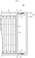
- FIG. 1 is a block diagram showing an apparatus for detecting swelling of a battery module according to an embodiment of the present disclosure.
- a swelling detection apparatus 10 includes a battery module housing 12 defining a space in which the battery module 11 is placed.
- the battery module 11 includes a plurality of battery cells 13 therein.
- the plurality of battery cells 13 may be stacked in a certain direction.
- a cartridge frame, a cooling fin and the like may be interposed between the battery cells 13.
- Each battery cell 13 has a structure in which an electrode assembly and an electrolyte are packaged by a pouch packaging material, but the present disclosure is not limited thereto.
- Each battery cell 13 includes a pair of electrodes exposed to the outside, and the electrodes of neighboring battery cells 13 may be connected in series and/or in parallel.
- the battery module housing 12 has an approximate box shape and defines a square space therein.
- the battery module 11 may be accommodated in the square space.
- the cross-sectional area of the battery module housing 12 is equal to or larger than the cross-sectional area of the battery module 11.
- the battery module housing 12 may include front, rear, left and right walls and upper and lower walls.
- the front, rear, left and right walls and the lower wall may be integrated to constitute a lower case 12a, and the upper wall may constitute an upper case 12b.
- the upper case 12b may serve as a cover.
- the lower case 12a and the upper case 12b may be made of metal or plastic and may be bonded to each other by known methods such as bolt, adhesive, and welding.
- the battery module 11 is placed on a bottom surface of the lower case 12a through the opening of the lower case 12a.
- the upper case 12b is coupled to the lower case 12a, the battery module 11 is accommodated in the battery module housing 12.
- the swelling detection apparatus 10 includes a swelling detection panel 14 attached to one surface of the battery module 11 and having an edge in contact with an inner surface of the battery module housing 12.
- the area of the swelling detection panel 14 is substantially the same as the cross section of the inner space in the battery module housing 12.
- the cross section refers to a section in a direction perpendicular to the ground.
- FIG. 2 is a partially sectioned view, taken along the line I-I' of FIG. 1 , to illustrate the structures of points A and B of FIG. 1 .
- the swelling detection apparatus 10 includes a slant portion 15 having a slant surface S, which protrudes from the inner surface of the battery module housing 12 and extends from a first location C1 adjacent to the edge of the swelling detection panel 14 to a second location C2 while forming a predetermined angle with the inner surface.
- the slant portion 15 may protrude at a plurality of points (see A and B of FIG. 1 ) along the edge of the swelling detection panel 14.
- the section of the slant portion 15 has a right-angled triangular shape, and the slant surface S of the slant portion 15 faces a right-angled corner of the right-angled triangle.
- the length of the slant portion 15 may be adjusted in advance according to the degree of swelling to be detected.
- the length of the slant portion 15 and the sensitivity of swelling detection are inversely proportional to each other. That is, as the sensitivity of swelling detection is higher, the length of the slant portion 15 becomes shorter.
- the swelling detection apparatus 10 includes a contact sensor unit 16 installed at the inner surface of the battery module housing 12 immediately adjacent to an end of the slant surface S corresponding to the second location C2 of the slant portion 15.
- the contact sensor unit 16 may be a piezoelectric sensor.
- the piezoelectric sensor refers to a sensor that outputs a voltage signal corresponding to the magnitude of a pressure when a specific object comes into contact to apply the pressure. Since the piezoelectric sensor is widely known in the art, it will not be described in detail here.
- the contact sensor unit 16 may be a button switch.
- the button switch refers to a switch that mechanically contacts a contact point of a switch or release the contact by the push/pull operation of the button.
- the button switch includes a spring for elastically biasing the button and two contact points whose electrical connection is selectively controlled by the push/pull operation of the elastically biased button.
- the button switch is a well-known electrical component widely known in the art and thus will not be described in detail here.
- one contact point of the button switch is connected to a DC power supply and the other contact point is connected to the control unit 18 via a conductive wire. Therefore, if the button switch is pushed, the two contacts may be connected to each other so that the voltage of the DC power supply is applied to the control unit 18.
- the swelling detection apparatus 10 may include an alarm unit 17 that visually or audibly outputs an alarm message.
- the alarm unit 17 may be a display or a speaker.
- the display outputs an alarm message in the form of text or graphic, and the speaker outputs an alarm message in the form of voice or alarm sound.
- the display may be a liquid crystal display, an organic light emitting diode display, or the like, but the present disclosure is not limited thereto.
- the swelling detection apparatus 10 includes a control unit 18 operably coupled to the contact sensor unit 16 and the alarm unit 17.
- the swelling detection panel 14 may move along the slant surface S of the slant portion 15 due to the pressure applied by the battery module 11.
- FIG. 3 is a sectional view showing a battery module having no battery cell in which the swelling phenomenon occurs
- FIG. 4 is a sectional view showing a battery module including a battery cell in which the swelling phenomenon occurs.
- the inflated battery cell presses the remaining cells to the left and right.
- the pressing force reaches an outermost end plate EP that is a component of the case of battery module 11. Since the end plate EP is made of a thin metal or plastic plate, the end plate EP is deformed into a curved surface when a pressure is applied thereto. As a result, the battery module 11 presses the swelling detection panel 14 toward the slant portion 15, and the pressed swelling detection panel 14 moves along the slant surface S.
- FIG. 5 is a diagram showing that the swelling detection panel 14 moves along the slant surface S of the slant portion 15
- FIG. 6 is a diagram showing that the swelling detection panel 14 is entirely deviated from the slant surface S of the slant portion 15.
- the swelling detection panel 14 Since the swelling detection panel 14 has an elastic force in itself as shown in the drawing, its shape is deformed to form a smooth curved surface when being moved along the slant surface S of the slant portion 15.
- the swelling detection panel 14 moves to the second point C2 of the slant surface S, and then suddenly is deviated from the slant surface of the slant portion 15 to make strong contact with the contact sensor unit 16.
- the swelling detection panel 14 is deviated from the slant surface S, the elastic biased state is released, so the edge portion of the swelling detection panel 14 applies a strong pressure to the contact sensor unit 16 for a short period of time.
- the contact sensor unit 16 is a piezoelectric sensor
- the piezoelectric sensor when the edge of the swelling detection panel 14 is deviated from the slant surface S of the slant portion 15 and applies a pressure to the piezoelectric sensor, the piezoelectric sensor outputs a voltage signal corresponding to the pressure to the control unit 18.
- the contact sensor unit 16 is a button switch
- the contact points of the button switch are connected to each other so that the voltage of the DC power supply connected to the button switch is applied to the control unit 18.
- control unit 18 may determine that the swelling detection panel 14 is deviated from the slant surface S of the slant portion 15 when at least one swelling detection signal is received from the plurality of contact sensor units 16.
- control unit 18 may control the alarm unit 17 to output an alarm message if the swelling detection signal is received from the contact sensor unit 16.
- control unit 18 visually outputs an alarm message through a display.
- control unit 18 audibly outputs an alarm message or an alarm sound through a speaker.
- the alarm message informs a user or driver of the device equipped with the battery module 11 that the battery cell(s) in the battery module 11 is in an excessively swelled state.
- the alarm message is output visually or audibly through alarm unit 17, it preferable that the user or driver stops the operation of battery module 11, then checks the state of battery module 11 and replaces the battery module 11 if necessary.
- the alarm unit 17 may be provided in a load device to which the battery module 10 is mounted.
- the alarm unit 17 may be an integrated vehicle information indicator provided to a dashboard of the electric-driven vehicle.
- control unit 18 may transmit the alarm message to a control system of the electric-driven vehicle through a communication interface.
- control system may request a driver to check the battery module 10 by visually or audibly outputting an alarm message through the integrated vehicle information indicator.
- the communication interface may support wired or wireless communication.
- the communication interface may support CAN communication or daisy chain communication.
- the alarm unit 17 may be provided to a load device as described, it should be understood that the present disclosure also includes an embodiment in which the control unit 18 outputs an alarm message to the alarm unit 17 through a control system provided in the load device.
- the swelling detection panel 14 may be used as a component of the battery module 11 by replacing the end plate of the battery module 11.
- FIG. 7 is a sectional view showing a battery module 11' in case the swelling detection panel 14' configures a part of the battery module 11'.
- the battery module 11' may include a plurality of cartridge 20. Each cartridge 20 surrounds at least one battery cell 13 included therein.
- the cartridge 20 may be made of a plastic or metal material with thermal conductivity. Electrodes (not shown) of the battery cell 13 are exposed at one side of the cartridge 20, and the exposed electrodes may be electrically connected by means of welding.
- the swelling detection panel 14' may be coupled to an outermost cartridge 20 that surrounds the outermost battery cell.
- the outermost cartridge 20 is located at a rightmost side on the drawing.
- the swelling detection panel 14' may have a snap-fit protrusion 31 on a surface opposite to the outermost cartridge 20, and a snap-fit groove 32 may be provided at the surface of the outermost cartridge 20.
- the swelling detection panel 14' may be snap-fitted to the outermost cartridge 20 to serve as the end plate of the battery module 11'.
- the snap-fit coupling allows the swelling detection panel 14' connected to the battery module 11' as an end plate to be easily separated from the outermost cartridge 20 when the swelling detection panel 14' is deviated from the second point C2 of the slant surface S while moving along the slant surface S of the slant portion 15.
- the height of the battery module 11' corresponds to the height of the internal space of the battery module housing 12. That is, the height between the top and the bottom of the swelling detection panel 14' may be substantially the same as the distance between the inner surface of the upper wall and the inner surface of the lower wall of the battery module housing 12.
- the snap-fit groove 32 may also be provided at an end wall of the battery module 11'.
- the swelling detection panel 14' may be snap-fitted to the end wall of the battery module 11'.
- the location of the snap-fit protrusion 31 may be adjusted to correspond to the location of the snap-fit groove 32 formed at the end wall of the battery module 11'.
- control unit 18 may optionally include a processor, an application-specific integrated circuit (ASIC), another chipset, a logic circuit, a register, a communication modem, a data processing device, or the like, known in the art to execute control logics.
- ASIC application-specific integrated circuit
- the control unit 18 may be implemented as a set of program modules.
- the program module may be stored in a memory and executed by a processor.
- the memory may be provided inside or outside the processor and be connected to the processor through various well-known computer components.
- control unit 18 may be combined, and the combined control logics may be written in a computer-readable code system and recorded in a computer-readable recording medium.
- the recording medium is not particularly limited as long as it is accessible by a processor included in a computer.
- the recording medium includes at least one selected from the group consisting of a ROM, a RAM, a register, a CD-ROM, a magnetic tape, a hard disk, a floppy disk and an optical data recording device.
- the code system may be distributed to a networked computer to be stored and executed therein.
- functional programs, codes and code segments for implementing the combined control logics may be easily inferred by programmers in the art to which the present disclosure belongs.
- the swelling detection apparatus 10 may be included in a battery management system 100 as shown in FIG. 8 .
- the battery management system 100 controls the overall operation related to charging and discharging of a battery and is a computing system called a battery management system (BMS) in the art.
- BMS battery management system
- the electric driving mechanism 200 may be an electric power device movable by electricity, such as an electric-driven vehicle, an electric bicycle, an electric motorcycle, an electric train, an electric ship and an electric plane, or a power tool having a motor, such as an electric drill and an electric grinder.
- FIG. 10 is a flowchart for illustrating a method for detecting swelling of a battery module according to an embodiment of the present disclosure.
- a battery module housing 12 defining a space in which the battery module 11 is mounted; a swelling detection panel 14 attached to one side surface of the battery module 11 and having an edge in contact with the inner surface of the battery module housing 12; a slant portion 15 configured to protrude from the inner surface of the battery module housing 12 and having a slant surface S extending from a first location C1 adjacent to the edge of the swelling detection panel 14 to a second location C2 while forming a predetermined angle with the inner surface; a contact sensor unit 16 installed to the inner surface of the battery module housing 12 immediately adjacent to the end of the slant surface S corresponding to the second location C2; an alarm unit 17 configured to output an alarm message visually or audibly; and a control unit 18 operably coupled to the contact sensor unit 16 and the alarm unit 17.
- Step S20 the contact sensor unit 16 outputs a swelling detection signal when the swelling detection panel 14 moves along the slant surface of the slant portion 15 to deviate from the second location C2 of the slant surface S and contact the contact sensor unit 16.
- each of the plurality of contact sensor units 16 may output a swelling detection signal.
- Step S30 if the control unit 18 receives at least one swelling detection signal from the plurality of contact sensor units 16, the control unit 18 outputs an alarm message through the alarm unit 17.
- the alarm unit 17 is a display or speaker. Accordingly, in Step S30, the control unit 18 may output the alarm message visually through the display or output the alarm message audibly through the speaker.
- the present disclosure it is possible to easily detect that a swelling phenomenon occurs in the battery cells included in the battery module.
- an excessive swelling phenomenon of the battery cells may be detected without changing the internal structure of the battery module, the stability of the battery module may be improved.
- the present disclosure may be usefully utilized when the battery module is mounted to an electric-driven vehicle.
- each element may be selectively integrated with other elements or each element may be divided into sub-elements for effective implementation control logic(s).
- functional identity can be acknowledged for the integrated or divided elements, the integrated or divided elements fall within the scope of the present disclosure.
- detection panel 14 to a second location C2 while forming a predetermined angle with the inner surface; a contact sensor unit 16 installed to the inner surface of the battery module housing 12 immediately adjacent to the end of the slant surface S corresponding to the second location C2; an alarm unit 17 configured to output an alarm message visually or audibly; and a control unit 18 operably coupled to the contact sensor unit 16 and the alarm unit 17.
- Step S20 the contact sensor unit 16 outputs a swelling detection signal when the swelling detection panel 14 moves along the slant surface of the slant portion 15 to deviate from the second location C2 of the slant surface S and contact the contact sensor unit 16.
- each of the plurality of contact sensor units 16 may output a swelling detection signal.
- Step S30 if the control unit 18 receives at least one swelling detection signal from the plurality of contact sensor units 16, the control unit 18 outputs an alarm message through the alarm unit 17.
- the alarm unit 17 is a display or speaker. Accordingly, in Step S30, the control unit 18 may output the alarm message visually through the display or output the alarm message audibly through the speaker.
- the present disclosure it is possible to easily detect that a swelling phenomenon occurs in the battery cells included in the battery module.
- an excessive swelling phenomenon of the battery cells may be detected without changing the internal structure of the battery module, the stability of the battery module may be improved.
- the present disclosure may be usefully utilized when the battery module is mounted to an electric-driven vehicle.
- each element may be selectively integrated with other elements or each element may be divided into sub-elements for effective implementation control logic(s).
- functional identity can be acknowledged for the integrated or divided elements, the integrated or divided elements fall within the scope of the present disclosure.
Landscapes
- Chemical & Material Sciences (AREA)
- Chemical Kinetics & Catalysis (AREA)
- Electrochemistry (AREA)
- General Chemical & Material Sciences (AREA)
- Engineering & Computer Science (AREA)
- Manufacturing & Machinery (AREA)
- Microelectronics & Electronic Packaging (AREA)
- Physics & Mathematics (AREA)
- General Physics & Mathematics (AREA)
- Aviation & Aerospace Engineering (AREA)
- Battery Mounting, Suspending (AREA)
- Secondary Cells (AREA)
Claims (17)
- Vorrichtung (10) zum Detektieren eines Anschwellens eines Batteriemoduls, umfassend:ein Batteriemodul-Gehäuse (12), welches dazu eingerichtet ist, einen Raum zu definieren, in welchem das Batteriemodul (11) platziert ist;eine Anschwellung-Detektionsplatte (14), welche dazu eingerichtet ist, an einer Seitenfläche des Batteriemoduls angebracht zu sein, und einen Rand in Kontakt mit einer Innenfläche des Batteriemodul-Gehäuses aufweist;einen Schrägabschnitt (15), welcher dazu eingerichtet ist, von der Innenfläche des Batteriemodul-Gehäuses vorzustehen und eine Schrägfläche (S) aufweist, welche sich von einer ersten Position (C1) benachbart zu dem Rand der Anschwellung-Detektionsplatte zu einer zweiten Position (C2) erstreckt, während ein vorbestimmter Winkel mit der Innenfläche des Batteriemodul-Gehäuses gebildet ist; eine Kontaktsensor-Einheit (16), welche an der Innenfläche des Batteriemodul-Gehäuses unmittelbar angrenzend an ein Ende der Schrägfläche installiert ist,welches der zweiten Position entspricht;eine Alarmeinheit (17), welche dazu eingerichtet ist, eine Alarmnachricht visuell oder hörbar auszugeben; undeine Steuereinheit (18), welche betriebsmäßig mit der Kontaktsensor-Einheit und der Alarmeinheit gekoppelt ist,wobei die Kontaktsensor-Einheit dazu eingerichtet ist, ein Anschwellung-Detektionssignal auszugeben, wenn sich die Anschwellung-Detektionsplatte entlang der Schrägfläche bewegt, um von der zweiten Position abzuweichen, so dass der Rand der Anschwellung-Detektionsplatte die Kontaktsensor-Einheit kontaktiert, unddie Steuereinheit dazu eingerichtet ist, die Alarmeinheit dazu zu steuern, die Alarmnachricht auszugeben, wenn das Anschwellung-Detektionssignal empfangen wird.
- Vorrichtung zum Detektieren eines Anschwellens eines Batteriemoduls nach Anspruch 1,
wobei der Schrägabschnitt an einer Mehrzahl von Punkten entlang des Rands der Anschwellung-Detektionsplatte vorsteht. - Vorrichtung zum Detektieren eines Anschwellens eines Batteriemoduls nach Anspruch 1,
wobei der Querschnitt des Schrägabschnitts ein rechtwinkliges Dreieck aufweist und die Schrägfläche des Schrägabschnitts zu einer rechtwinkligen Ecke des rechtwinkligen Dreiecks weist. - Vorrichtung zum Detektieren eines Anschwellens eines Batteriemoduls nach Anspruch 1,
wobei die Anschwellung-Detektionsplatte aus einem elastischen Kunststoff hergestellt ist. - Vorrichtung zum Detektieren eines Anschwellens eines Batteriemoduls nach Anspruch 1,
wobei die Kontaktsensor-Einheit ein piezoelektrischer Sensor ist. - Vorrichtung zum Detektieren eines Anschwellens eines Batteriemoduls nach Anspruch 5,
wobei wenn der Rand der Anschwellung-Detektionsplatte von der Schrägfläche des Schrägabschnitts abgelenkt wird und einen Druck auf den piezoelektrischen Sensor ausübt, der piezoelektrische Sensor ein Spannungssignal, welches dem Druck entspricht, zu der Steuereinheit ausgibt. - Vorrichtung zum Detektieren eines Anschwellens eines Batteriemoduls nach Anspruch 1,
wobei die Kontaktsensor-Einheit ein Knopfschalter ist. - Vorrichtung zum Detektieren eines Anschwellens eines Batteriemoduls nach Anspruch 7,
wobei der Knopfschalter ein Ende mit einer DC-Leistungsquelle verbunden und das andere Ende mit der Steuereinheit verbunden aufweist. - Vorrichtung zum Detektieren eines Anschwellens eines Batteriemoduls nach Anspruch 8,
wobei wenn der Rand der Anschwellung-Detektionsplatte von der Schrägfläche des Schrägabschnitts abgelenkt wird und einen Druck auf den Knopfschalter ausübt, um den Knopf zu drücken, das Ende und das andere Ende des Knopfschalters miteinander verbunden sind, so dass die Spannung der DC-Leistungsquelle, welche mit dem Knopfschalter verbunden ist, an die Steuereinheit angelegt ist. - Batterie-Verwaltungssystem (100), umfassend die Vorrichtung zum Detektieren eines Anschwellens eines Batteriemoduls nach einem der Ansprüche 1-9.
- Elektrischer Antriebsmechanismus (200), umfassend die Vorrichtung zum Detektieren eines Anschwellens eines Batteriemoduls nach einem der Ansprüche 1-9.
- Verfahren zum Detektieren eines Anschwellens eines Batteriemoduls, umfassend:(a) Bereitstellen einer Vorrichtung (10) zum Detektieren eines Anschwellens eines Batteriemoduls, umfassend ein Batteriemodul-Gehäuse (12), welches dazu eingerichtet ist, einen Raum zu definieren, in welchem ein Batteriemodul (11) platziert ist; eine Anschwellung-Detektionsplatte (14), welche an einer Seitenfläche des Batteriemoduls angebracht ist und einen Rand in Kontakt mit einer Innenfläche des Batteriemodul-Gehäuses aufweist; einen Schrägabschnitt (15), welcher dazu eingerichtet ist, von der Innenfläche des Batteriemodul-Gehäuses vorzustehen und eine Schrägfläche (S) aufweist, welche sich von einer ersten Position (C1) benachbart zu dem Rand der Anschwellung-Detektionsplatte zu einer zweiten Position (C2) erstreckt, während ein vorbestimmter Winkel mit der Innenfläche des Batteriemodul-Gehäuses gebildet ist; eine Kontaktsensor-Einheit (16), welche an der Innenfläche des Batteriemodul-Gehäuses unmittelbar angrenzend an ein Ende der Schrägfläche installiert ist, welches der zweiten Position entspricht; eine Alarmeinheit (17), welche dazu eingerichtet ist, eine Alarmnachricht visuell oder hörbar auszugeben; und eine Steuereinheit (18), welche betriebsmäßig mit der Kontaktsensor-Einheit und der Alarmeinheit gekoppelt ist,(b) durch die Kontaktsensor-Einheit, Ausgeben eines Anschwellung-Detektionssignals, wenn sich die Anschwellung-Detektionsplatte entlang der Schrägfläche bewegt, um von der zweiten Position abgelenkt zu werden, so dass der Rand der Anschwellung-Detektionsplatte die Kontaktsensor-Einheit kontaktiert; und(c) durch die Steuereinheit, Steuern der Alarmeinheit, um die Alarmnachricht auszugeben, nachdem das Anschwellung-Detektionssignal empfangen wird.
- Verfahren zum Detektieren eines Anschwellens eines Batteriemoduls nach Anspruch 12,
wobei die Anschwellung-Detektionsplatte aus einem elastischen Kunststoff hergestellt wird. - Verfahren zum Detektieren eines Anschwellens eines Batteriemoduls nach Anspruch 12,
wobei der Kontaktsensor ein piezoelektrischer Sensor ist. - Verfahren zum Detektieren eines Anschwellens eines Batteriemoduls nach Anspruch 12,
wobei die Kontaktsensor-Einheit ein Knopfschalter ist. - Verfahren zum Detektieren eines Anschwellens eines Batteriemoduls nach Anspruch 15,
wobei der Knopfschalter ein Ende mit einer DC-Leistungsquelle verbunden und das andere Ende mit der Steuereinheit verbunden aufweist. - Verfahren zum Detektieren eines Anschwellens eines Batteriemoduls nach Anspruch 12,
wobei der Schrägabschnitt an einer Mehrzahl von Punkten entlang des Rands der Anschwellung-Detektionsplatte vorsteht.
Applications Claiming Priority (3)
| Application Number | Priority Date | Filing Date | Title |
|---|---|---|---|
| KR20190149841 | 2019-11-20 | ||
| KR1020200149665A KR20210061938A (ko) | 2019-11-20 | 2020-11-10 | 배터리 모듈의 스웰링 감지 장치 및 방법 |
| PCT/KR2020/015888 WO2021101168A1 (ko) | 2019-11-20 | 2020-11-12 | 배터리 모듈의 스웰링 감지 장치 및 방법 |
Publications (3)
| Publication Number | Publication Date |
|---|---|
| EP4024562A1 EP4024562A1 (de) | 2022-07-06 |
| EP4024562A4 EP4024562A4 (de) | 2024-06-12 |
| EP4024562B1 true EP4024562B1 (de) | 2025-04-16 |
Family
ID=75980846
Family Applications (1)
| Application Number | Title | Priority Date | Filing Date |
|---|---|---|---|
| EP20889637.3A Active EP4024562B1 (de) | 2019-11-20 | 2020-11-12 | Vorrichtung und verfahren zur erfassung der schwellung eines batteriemoduls |
Country Status (7)
| Country | Link |
|---|---|
| US (1) | US20230006273A1 (de) |
| EP (1) | EP4024562B1 (de) |
| JP (1) | JP7306645B2 (de) |
| CN (1) | CN114175357B (de) |
| ES (1) | ES3025687T3 (de) |
| HU (1) | HUE071369T2 (de) |
| WO (1) | WO2021101168A1 (de) |
Families Citing this family (6)
| Publication number | Priority date | Publication date | Assignee | Title |
|---|---|---|---|---|
| AT524291B1 (de) * | 2020-10-01 | 2022-10-15 | Avl List Gmbh | Vorrichtung zum testen zumindest einer batteriezelle |
| WO2022093270A1 (en) * | 2020-10-30 | 2022-05-05 | Hewlett-Packard Development Company, L.P. | Detect and prevent battery swelling |
| DE102022103204A1 (de) | 2022-02-11 | 2023-08-17 | Bayerische Motoren Werke Aktiengesellschaft | Zellmodul mit einer Detektionseinrichtung zur Erkennung einer Zellausdehnung |
| JP2024098886A (ja) * | 2023-01-11 | 2024-07-24 | 株式会社東芝 | 膨れ検出装置 |
| CN116913061B (zh) * | 2023-09-12 | 2023-12-12 | 合肥优晟电力科技有限公司 | 一种电池鼓包监测警报装置及警报方法 |
| CN117977033B (zh) * | 2024-03-29 | 2025-02-25 | 宁德时代新能源科技股份有限公司 | 电池箱体、电池、电池管理方法及用电装置 |
Family Cites Families (26)
| Publication number | Priority date | Publication date | Assignee | Title |
|---|---|---|---|---|
| JP2002117911A (ja) | 2000-10-06 | 2002-04-19 | Nec Mobile Energy Kk | 電池搭載機器 |
| JP2004039512A (ja) | 2002-07-05 | 2004-02-05 | Japan Storage Battery Co Ltd | 電池 |
| KR100878702B1 (ko) * | 2005-11-30 | 2009-01-14 | 주식회사 엘지화학 | 이차전지용 안전장치 및 그것을 포함하는 전지팩 |
| JP5048366B2 (ja) | 2007-03-16 | 2012-10-17 | 産電子工業株式会社 | 保護装置 |
| JP5217214B2 (ja) * | 2007-03-30 | 2013-06-19 | Tdk株式会社 | 電源装置及び電気化学素子の膨張検知方法 |
| FR2916306B1 (fr) | 2007-05-15 | 2009-07-17 | Batscap Sa | Module pour ensembles de stockage d'energie electrique permettant la detection du vieillissement desdits ensembles. |
| KR101293206B1 (ko) * | 2007-06-12 | 2013-08-05 | 주식회사 엘지화학 | 2차전지 카트리지 모듈의 부풀림 검출/보호 시스템 및 그방법, 이에 보호받는 2차전지 카트리지 모듈 |
| JP2009278763A (ja) | 2008-05-14 | 2009-11-26 | Nextage:Kk | 充電器及び充電方法 |
| JP5017189B2 (ja) * | 2008-06-13 | 2012-09-05 | 富士通テレコムネットワークス株式会社 | 膨張検出器 |
| KR101419746B1 (ko) * | 2008-10-13 | 2014-07-15 | 주식회사 엘지화학 | 배터리 셀의 swelling 감지장치 |
| KR101072955B1 (ko) | 2009-08-14 | 2011-10-12 | 에스비리모티브 주식회사 | 전지 모듈 |
| JP5489797B2 (ja) * | 2010-03-17 | 2014-05-14 | 三菱重工業株式会社 | 電池システム |
| US8395519B2 (en) | 2010-11-19 | 2013-03-12 | General Electric Company | Device and method of determining safety in a battery pack |
| KR101272915B1 (ko) * | 2011-07-14 | 2013-06-11 | 기아자동차주식회사 | 차량의 배터리팩 안전장치 |
| EP2645527A1 (de) * | 2012-03-26 | 2013-10-02 | Samsung SDI Co., Ltd. | Batteriepack |
| JP6015174B2 (ja) * | 2012-07-05 | 2016-10-26 | 株式会社デンソー | 電池ユニット |
| KR101836516B1 (ko) * | 2012-07-19 | 2018-03-08 | 현대자동차주식회사 | Cid 구조를 갖는 배터리 시스템 및 그 운영방법 |
| KR101449306B1 (ko) | 2013-06-28 | 2014-10-08 | 현대자동차주식회사 | 배터리 과충전 보호장치 |
| US20170092997A1 (en) * | 2014-03-31 | 2017-03-30 | Toyo Tire & Rubber Co., Ltd. | Deformation detection sensor for sealed secondary battery |
| KR101738215B1 (ko) * | 2014-06-25 | 2017-05-19 | 에스케이이노베이션 주식회사 | 배터리 셀 조립체의 스웰링 현상을 감지하는 배터리 모듈 |
| KR101950463B1 (ko) * | 2015-10-06 | 2019-02-20 | 주식회사 엘지화학 | 전지셀의 팽창을 감지하기 위한 프로브를 포함하고 있는 전지모듈 |
| KR102178959B1 (ko) * | 2017-04-06 | 2020-11-13 | 주식회사 엘지화학 | 엔드 플레이트, 배터리 모듈, 배터리 모듈을 포함하는 배터리 팩 및 배터리 팩을 포함하는 자동차 |
| CN108878698B (zh) * | 2017-05-09 | 2021-08-13 | 华为技术有限公司 | 电池包、电池储能系统和电动汽车 |
| KR102425827B1 (ko) * | 2017-06-16 | 2022-07-27 | 삼성에스디아이 주식회사 | 배터리 모듈 |
| US10641835B2 (en) | 2018-03-15 | 2020-05-05 | Ascending Energy Inc. | Health monitoring and safety protection for lithium ion battery modules and applications |
| CN215451507U (zh) | 2021-05-21 | 2022-01-07 | 昆山研达电脑科技有限公司 | 电池膨胀提示装置 |
-
2020
- 2020-11-12 ES ES20889637T patent/ES3025687T3/es active Active
- 2020-11-12 HU HUE20889637A patent/HUE071369T2/hu unknown
- 2020-11-12 WO PCT/KR2020/015888 patent/WO2021101168A1/ko not_active Ceased
- 2020-11-12 US US17/778,084 patent/US20230006273A1/en active Pending
- 2020-11-12 CN CN202080053552.2A patent/CN114175357B/zh active Active
- 2020-11-12 JP JP2022516725A patent/JP7306645B2/ja active Active
- 2020-11-12 EP EP20889637.3A patent/EP4024562B1/de active Active
Also Published As
| Publication number | Publication date |
|---|---|
| WO2021101168A1 (ko) | 2021-05-27 |
| EP4024562A1 (de) | 2022-07-06 |
| ES3025687T3 (en) | 2025-06-09 |
| CN114175357B (zh) | 2023-09-12 |
| JP2022549099A (ja) | 2022-11-24 |
| HUE071369T2 (hu) | 2025-08-28 |
| CN114175357A (zh) | 2022-03-11 |
| US20230006273A1 (en) | 2023-01-05 |
| EP4024562A4 (de) | 2024-06-12 |
| JP7306645B2 (ja) | 2023-07-11 |
Similar Documents
| Publication | Publication Date | Title |
|---|---|---|
| EP4024562B1 (de) | Vorrichtung und verfahren zur erfassung der schwellung eines batteriemoduls | |
| JP5883944B2 (ja) | 安全性の向上した電池モジュール及びこれを含む電池パック | |
| CN107534191B (zh) | 包括用于检测电池单体的膨胀的探针的电池模块 | |
| EP3211708A1 (de) | Batteriemodul | |
| KR20210061938A (ko) | 배터리 모듈의 스웰링 감지 장치 및 방법 | |
| US11799138B2 (en) | Apparatus for detecting thermal runaway of battery for electric vehicle | |
| KR101965447B1 (ko) | 배터리팩과 이를 적용한 배터리 모듈 | |
| CN113678310B (zh) | 电池组 | |
| CN107834125B (zh) | 牵引电池和具有这样的电池的车辆 | |
| JP5845908B2 (ja) | 電源装置 | |
| KR20210135141A (ko) | 소화부가 구비된 전지 모듈 | |
| CN114355202A (zh) | 用于检测电动车辆电池的热失控的装置 | |
| CN115832486B (zh) | 电池单体、电池和用电装置 | |
| KR20200084403A (ko) | 전기자동차용 배터리 모듈 및 이의 제어방법 | |
| KR20220067119A (ko) | 전지 모듈 및 이를 포함하는 전지팩 | |
| CN115917834B (zh) | 电池模块、包括该电池模块的电池组和电动车辆 | |
| KR102434893B1 (ko) | 내압 감지형 변색 파우치형 전지 | |
| KR102846094B1 (ko) | 스웰링 감지 성능이 개선된 배터리 팩 | |
| CN114103644A (zh) | 用于电动车辆的电池的热失控检测装置 | |
| KR101760556B1 (ko) | 이차전지팩 및 그를 탑재한 차량 | |
| KR20220049141A (ko) | 셀케이스의 팽창확인이 용이한 이차전지 및 팽창 여부 검사 방법 | |
| CN116250113B (zh) | 电池、用电装置、制备电池的方法及其装置和报警方法 | |
| CN113966560B (zh) | 包括配置为测量内部压力的压力感测装置的袋形二次电池 | |
| EP4016696A1 (de) | System und verfahren zur ultraschallinspektion | |
| US20250297906A1 (en) | Road surface interference sensor and monitoring system |
Legal Events
| Date | Code | Title | Description |
|---|---|---|---|
| STAA | Information on the status of an ep patent application or granted ep patent |
Free format text: STATUS: THE INTERNATIONAL PUBLICATION HAS BEEN MADE |
|
| PUAI | Public reference made under article 153(3) epc to a published international application that has entered the european phase |
Free format text: ORIGINAL CODE: 0009012 |
|
| STAA | Information on the status of an ep patent application or granted ep patent |
Free format text: STATUS: REQUEST FOR EXAMINATION WAS MADE |
|
| 17P | Request for examination filed |
Effective date: 20220331 |
|
| AK | Designated contracting states |
Kind code of ref document: A1 Designated state(s): AL AT BE BG CH CY CZ DE DK EE ES FI FR GB GR HR HU IE IS IT LI LT LU LV MC MK MT NL NO PL PT RO RS SE SI SK SM TR |
|
| DAV | Request for validation of the european patent (deleted) | ||
| DAX | Request for extension of the european patent (deleted) | ||
| A4 | Supplementary search report drawn up and despatched |
Effective date: 20240514 |
|
| RIC1 | Information provided on ipc code assigned before grant |
Ipc: H01M 10/42 20060101ALI20240507BHEP Ipc: H01M 50/20 20210101ALI20240507BHEP Ipc: H01M 10/48 20060101AFI20240507BHEP |
|
| REG | Reference to a national code |
Ref country code: DE Ref legal event code: R079 Free format text: PREVIOUS MAIN CLASS: H01M0010480000 Ipc: G01B0007160000 Ref document number: 602020049722 Country of ref document: DE |
|
| GRAP | Despatch of communication of intention to grant a patent |
Free format text: ORIGINAL CODE: EPIDOSNIGR1 |
|
| RIC1 | Information provided on ipc code assigned before grant |
Ipc: H01M 50/249 20210101ALI20241125BHEP Ipc: H01M 50/289 20210101ALI20241125BHEP Ipc: H01M 10/44 20060101ALI20241125BHEP Ipc: H01M 50/20 20210101ALI20241125BHEP Ipc: H01M 10/42 20060101ALI20241125BHEP Ipc: H01M 10/48 20060101ALI20241125BHEP Ipc: G01B 7/16 20060101AFI20241125BHEP |
|
| STAA | Information on the status of an ep patent application or granted ep patent |
Free format text: STATUS: GRANT OF PATENT IS INTENDED |
|
| INTG | Intention to grant announced |
Effective date: 20250102 |
|
| P01 | Opt-out of the competence of the unified patent court (upc) registered |
Free format text: CASE NUMBER: APP_580/2025 Effective date: 20250107 |
|
| GRAS | Grant fee paid |
Free format text: ORIGINAL CODE: EPIDOSNIGR3 |
|
| GRAA | (expected) grant |
Free format text: ORIGINAL CODE: 0009210 |
|
| STAA | Information on the status of an ep patent application or granted ep patent |
Free format text: STATUS: THE PATENT HAS BEEN GRANTED |
|
| AK | Designated contracting states |
Kind code of ref document: B1 Designated state(s): AL AT BE BG CH CY CZ DE DK EE ES FI FR GB GR HR HU IE IS IT LI LT LU LV MC MK MT NL NO PL PT RO RS SE SI SK SM TR |
|
| REG | Reference to a national code |
Ref country code: GB Ref legal event code: FG4D |
|
| REG | Reference to a national code |
Ref country code: CH Ref legal event code: EP Ref country code: DE Ref legal event code: R096 Ref document number: 602020049722 Country of ref document: DE |
|
| REG | Reference to a national code |
Ref country code: IE Ref legal event code: FG4D |
|
| REG | Reference to a national code |
Ref country code: ES Ref legal event code: FG2A Ref document number: 3025687 Country of ref document: ES Kind code of ref document: T3 Effective date: 20250609 |
|
| REG | Reference to a national code |
Ref country code: NL Ref legal event code: MP Effective date: 20250416 |
|
| REG | Reference to a national code |
Ref country code: HU Ref legal event code: AG4A Ref document number: E071369 Country of ref document: HU |
|
| PG25 | Lapsed in a contracting state [announced via postgrant information from national office to epo] |
Ref country code: NL Free format text: LAPSE BECAUSE OF FAILURE TO SUBMIT A TRANSLATION OF THE DESCRIPTION OR TO PAY THE FEE WITHIN THE PRESCRIBED TIME-LIMIT Effective date: 20250416 |
|
| REG | Reference to a national code |
Ref country code: AT Ref legal event code: MK05 Ref document number: 1785948 Country of ref document: AT Kind code of ref document: T Effective date: 20250416 |
|
| PG25 | Lapsed in a contracting state [announced via postgrant information from national office to epo] |
Ref country code: PT Free format text: LAPSE BECAUSE OF FAILURE TO SUBMIT A TRANSLATION OF THE DESCRIPTION OR TO PAY THE FEE WITHIN THE PRESCRIBED TIME-LIMIT Effective date: 20250818 Ref country code: FI Free format text: LAPSE BECAUSE OF FAILURE TO SUBMIT A TRANSLATION OF THE DESCRIPTION OR TO PAY THE FEE WITHIN THE PRESCRIBED TIME-LIMIT Effective date: 20250416 |
|
| REG | Reference to a national code |
Ref country code: LT Ref legal event code: MG9D |
|
| PG25 | Lapsed in a contracting state [announced via postgrant information from national office to epo] |
Ref country code: NO Free format text: LAPSE BECAUSE OF FAILURE TO SUBMIT A TRANSLATION OF THE DESCRIPTION OR TO PAY THE FEE WITHIN THE PRESCRIBED TIME-LIMIT Effective date: 20250716 Ref country code: GR Free format text: LAPSE BECAUSE OF FAILURE TO SUBMIT A TRANSLATION OF THE DESCRIPTION OR TO PAY THE FEE WITHIN THE PRESCRIBED TIME-LIMIT Effective date: 20250717 |
|
| PG25 | Lapsed in a contracting state [announced via postgrant information from national office to epo] |
Ref country code: PL Free format text: LAPSE BECAUSE OF FAILURE TO SUBMIT A TRANSLATION OF THE DESCRIPTION OR TO PAY THE FEE WITHIN THE PRESCRIBED TIME-LIMIT Effective date: 20250416 |
|
| PG25 | Lapsed in a contracting state [announced via postgrant information from national office to epo] |
Ref country code: BG Free format text: LAPSE BECAUSE OF FAILURE TO SUBMIT A TRANSLATION OF THE DESCRIPTION OR TO PAY THE FEE WITHIN THE PRESCRIBED TIME-LIMIT Effective date: 20250416 |
|
| PG25 | Lapsed in a contracting state [announced via postgrant information from national office to epo] |
Ref country code: HR Free format text: LAPSE BECAUSE OF FAILURE TO SUBMIT A TRANSLATION OF THE DESCRIPTION OR TO PAY THE FEE WITHIN THE PRESCRIBED TIME-LIMIT Effective date: 20250416 |
|
| PG25 | Lapsed in a contracting state [announced via postgrant information from national office to epo] |
Ref country code: AT Free format text: LAPSE BECAUSE OF FAILURE TO SUBMIT A TRANSLATION OF THE DESCRIPTION OR TO PAY THE FEE WITHIN THE PRESCRIBED TIME-LIMIT Effective date: 20250416 |
|
| PG25 | Lapsed in a contracting state [announced via postgrant information from national office to epo] |
Ref country code: RS Free format text: LAPSE BECAUSE OF FAILURE TO SUBMIT A TRANSLATION OF THE DESCRIPTION OR TO PAY THE FEE WITHIN THE PRESCRIBED TIME-LIMIT Effective date: 20250716 |
|
| PG25 | Lapsed in a contracting state [announced via postgrant information from national office to epo] |
Ref country code: IS Free format text: LAPSE BECAUSE OF FAILURE TO SUBMIT A TRANSLATION OF THE DESCRIPTION OR TO PAY THE FEE WITHIN THE PRESCRIBED TIME-LIMIT Effective date: 20250816 |
|
| PG25 | Lapsed in a contracting state [announced via postgrant information from national office to epo] |
Ref country code: LV Free format text: LAPSE BECAUSE OF FAILURE TO SUBMIT A TRANSLATION OF THE DESCRIPTION OR TO PAY THE FEE WITHIN THE PRESCRIBED TIME-LIMIT Effective date: 20250416 |
|
| PGFP | Annual fee paid to national office [announced via postgrant information from national office to epo] |
Ref country code: HU Payment date: 20251127 Year of fee payment: 6 |
|
| PGFP | Annual fee paid to national office [announced via postgrant information from national office to epo] |
Ref country code: DE Payment date: 20251020 Year of fee payment: 6 |
|
| PGFP | Annual fee paid to national office [announced via postgrant information from national office to epo] |
Ref country code: GB Payment date: 20251023 Year of fee payment: 6 |
|
| PG25 | Lapsed in a contracting state [announced via postgrant information from national office to epo] |
Ref country code: SM Free format text: LAPSE BECAUSE OF FAILURE TO SUBMIT A TRANSLATION OF THE DESCRIPTION OR TO PAY THE FEE WITHIN THE PRESCRIBED TIME-LIMIT Effective date: 20250416 Ref country code: DK Free format text: LAPSE BECAUSE OF FAILURE TO SUBMIT A TRANSLATION OF THE DESCRIPTION OR TO PAY THE FEE WITHIN THE PRESCRIBED TIME-LIMIT Effective date: 20250416 |
|
| PGFP | Annual fee paid to national office [announced via postgrant information from national office to epo] |
Ref country code: FR Payment date: 20251021 Year of fee payment: 6 |
|
| PGFP | Annual fee paid to national office [announced via postgrant information from national office to epo] |
Ref country code: BE Payment date: 20251020 Year of fee payment: 6 |
|
| PG25 | Lapsed in a contracting state [announced via postgrant information from national office to epo] |
Ref country code: CZ Free format text: LAPSE BECAUSE OF FAILURE TO SUBMIT A TRANSLATION OF THE DESCRIPTION OR TO PAY THE FEE WITHIN THE PRESCRIBED TIME-LIMIT Effective date: 20250416 |
|
| PG25 | Lapsed in a contracting state [announced via postgrant information from national office to epo] |
Ref country code: EE Free format text: LAPSE BECAUSE OF FAILURE TO SUBMIT A TRANSLATION OF THE DESCRIPTION OR TO PAY THE FEE WITHIN THE PRESCRIBED TIME-LIMIT Effective date: 20250416 |
|
| PG25 | Lapsed in a contracting state [announced via postgrant information from national office to epo] |
Ref country code: SK Free format text: LAPSE BECAUSE OF FAILURE TO SUBMIT A TRANSLATION OF THE DESCRIPTION OR TO PAY THE FEE WITHIN THE PRESCRIBED TIME-LIMIT Effective date: 20250416 Ref country code: RO Free format text: LAPSE BECAUSE OF FAILURE TO SUBMIT A TRANSLATION OF THE DESCRIPTION OR TO PAY THE FEE WITHIN THE PRESCRIBED TIME-LIMIT Effective date: 20250416 |
|
| PG25 | Lapsed in a contracting state [announced via postgrant information from national office to epo] |
Ref country code: IT Free format text: LAPSE BECAUSE OF FAILURE TO SUBMIT A TRANSLATION OF THE DESCRIPTION OR TO PAY THE FEE WITHIN THE PRESCRIBED TIME-LIMIT Effective date: 20250416 |
|
| PGFP | Annual fee paid to national office [announced via postgrant information from national office to epo] |
Ref country code: ES Payment date: 20251215 Year of fee payment: 6 |
|
| PLBE | No opposition filed within time limit |
Free format text: ORIGINAL CODE: 0009261 |
|
| STAA | Information on the status of an ep patent application or granted ep patent |
Free format text: STATUS: NO OPPOSITION FILED WITHIN TIME LIMIT |