EP4023828B1 - Befestigungsvorrichtung und sanitärgegenstand damit - Google Patents
Befestigungsvorrichtung und sanitärgegenstand damit Download PDFInfo
- Publication number
- EP4023828B1 EP4023828B1 EP20878892.7A EP20878892A EP4023828B1 EP 4023828 B1 EP4023828 B1 EP 4023828B1 EP 20878892 A EP20878892 A EP 20878892A EP 4023828 B1 EP4023828 B1 EP 4023828B1
- Authority
- EP
- European Patent Office
- Prior art keywords
- locking
- connection member
- fitting surface
- base
- fixing device
- Prior art date
- Legal status (The legal status is an assumption and is not a legal conclusion. Google has not performed a legal analysis and makes no representation as to the accuracy of the status listed.)
- Active
Links
Images


Classifications
-
- E—FIXED CONSTRUCTIONS
- E03—WATER SUPPLY; SEWERAGE
- E03D—WATER-CLOSETS OR URINALS WITH FLUSHING DEVICES; FLUSHING VALVES THEREFOR
- E03D11/00—Other component parts of water-closets, e.g. noise-reducing means in the flushing system, flushing pipes mounted in the bowl, seals for the bowl outlet, devices preventing overflow of the bowl contents; devices forming a water seal in the bowl after flushing, devices eliminating obstructions in the bowl outlet or preventing backflow of water and excrements from the waterpipe
- E03D11/13—Parts or details of bowls; Special adaptations of pipe joints or couplings for use with bowls, e.g. provisions in bowl construction preventing backflow of waste-water from the bowl in the flushing pipe or cistern, provisions for a secondary flushing, for noise-reducing
- E03D11/14—Means for connecting the bowl to the wall, e.g. to a wall outlet
-
- F—MECHANICAL ENGINEERING; LIGHTING; HEATING; WEAPONS; BLASTING
- F16—ENGINEERING ELEMENTS AND UNITS; GENERAL MEASURES FOR PRODUCING AND MAINTAINING EFFECTIVE FUNCTIONING OF MACHINES OR INSTALLATIONS; THERMAL INSULATION IN GENERAL
- F16B—DEVICES FOR FASTENING OR SECURING CONSTRUCTIONAL ELEMENTS OR MACHINE PARTS TOGETHER, e.g. NAILS, BOLTS, CIRCLIPS, CLAMPS, CLIPS OR WEDGES; JOINTS OR JOINTING
- F16B21/00—Means for preventing relative axial movement of a pin, spigot, shaft or the like and a member surrounding it; Stud-and-socket releasable fastenings
- F16B21/10—Means for preventing relative axial movement of a pin, spigot, shaft or the like and a member surrounding it; Stud-and-socket releasable fastenings by separate parts
- F16B21/12—Means for preventing relative axial movement of a pin, spigot, shaft or the like and a member surrounding it; Stud-and-socket releasable fastenings by separate parts with locking-pins or split-pins thrust into holes
- F16B21/125—Means for preventing relative axial movement of a pin, spigot, shaft or the like and a member surrounding it; Stud-and-socket releasable fastenings by separate parts with locking-pins or split-pins thrust into holes radially resilient or with a snap-action member, e.g. elastic tooth, pawl with spring, resilient coil or wire
-
- F—MECHANICAL ENGINEERING; LIGHTING; HEATING; WEAPONS; BLASTING
- F16—ENGINEERING ELEMENTS AND UNITS; GENERAL MEASURES FOR PRODUCING AND MAINTAINING EFFECTIVE FUNCTIONING OF MACHINES OR INSTALLATIONS; THERMAL INSULATION IN GENERAL
- F16B—DEVICES FOR FASTENING OR SECURING CONSTRUCTIONAL ELEMENTS OR MACHINE PARTS TOGETHER, e.g. NAILS, BOLTS, CIRCLIPS, CLAMPS, CLIPS OR WEDGES; JOINTS OR JOINTING
- F16B21/00—Means for preventing relative axial movement of a pin, spigot, shaft or the like and a member surrounding it; Stud-and-socket releasable fastenings
- F16B21/10—Means for preventing relative axial movement of a pin, spigot, shaft or the like and a member surrounding it; Stud-and-socket releasable fastenings by separate parts
- F16B21/16—Means for preventing relative axial movement of a pin, spigot, shaft or the like and a member surrounding it; Stud-and-socket releasable fastenings by separate parts with grooves or notches in the pin or shaft
Definitions
- the invention relates to the technical field of bathroom accessories, in particular to a fixing device and sanitary ware having same.
- a wall-hung toilet is a toilet hung on a wall, including sitting toilets and urinals.
- a wall-hung toilet When a wall-hung toilet is installed, a water tank and a drain pipe are placed inside the wall, so there is only a toilet body on the wall and the water tank is invisible, which increases the space utilization rate of a bathroom. Moreover, the wall-hung toilet is hung on the wall surface and has a certain distance from the ground, which saves time and effort when cleaning the bathroom. Most importantly, the wall can well isolate the flushing noise, which has a good noise reduction effect. Because of its fashionable appearance, the character of being easy to clean, and good performance in saving space and reducing noise, the wall-hung toilet has gradually become popular in China in recent years and is widely used in upscale apartments.
- CN 110206113 A relates to a toilet locking device and discloses a fixing device for fixedly connecting a first component (wall body) and a second component (toilet seat body).
- DE 10 2017 116113 A1 relates to a clamping mechanism with a locking function.
- WO 2016/041624 A1 relates to a securing device for securing a sanitary object made of ceramic.
- a locking device is used to fasten the toilet.
- the toilet needs to be held by one person so that another person can fasten it, so more than one person is needed for installation, which is inconvenient.
- the invention provides a fixing device and sanitary ware having same.
- a pre-locking mechanism By means of a limiting function of a pre-locking mechanism, the sanitary ware is pre-mounted, mounting can be realized by a single person, the operation is simple and convenient, and time and effort are saved.
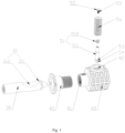
- a fixing device is used for fixedly connecting a first component (10) and a second component (20).
- the fixing device comprises a connection member (30) connected to the first component (10) and a base (40) connected to the second component (20), the connection member (30) configured for being in lock connection with the base (40) by means of a locking mechanism (50).
- the fixing device further comprises a pre-locking mechanism having a pre-locking state and an unlocking state; before the locking mechanism locks the connection member (30) and the base (40), the pre-locking mechanism is in the pre-locking state, and the connection member (30) and the base (40) are in limited fitting by means of the pre-locking mechanism, so as to prevent the connection member (30) from being detached from the base (40), and when the pre-locking mechanism is in the unlocking state, the connection member (30) can be detached from the base (40) wherein the first component (10) is a wall or a rack, the second component (20) is a body of the sanitary ware.
- the locking mechanism (50) is arranged on the base (40), and the pre-locking mechanism comprises a pre-locking fitting surface (311) arranged on the connection member (30) and a pre-locking part (54) arranged on the locking mechanism (50), wherein the pre-locking fitting surface (311) and/or the pre-locking part (54) can move between an unlocking position and a pre-locking position.
- the pre-locking fitting surface (311) and/or the pre-locking part (54) is in the pre-locking position, and the pre-locking fitting surface (311) is in limited fitting with the pre-locking part (54), so that the connection member (30) and the base (40) are in limited fitting.
- the pre-locking fitting surface (311) and/or the pre-locking part (54) is in the unlocking position, and the pre-locking fitting surface (311) is separated from the pre-locking part (54), so that the connection member (30) can be separated from the base (40).
- connection member (30) is also provided with a locking fitting surface (312), and the locking mechanism (50) locks and connects the connection member (30) and the base (40) through locking fitting with the locking fitting surface (312).
- the connection member (30) is a connecting rod
- the base (40) is internally provided with a connecting channel (41) into which the connecting rod is inserted
- a side wall of the connecting channel (41) is provided with a radial through hole (42) communicating with the connecting channel (41)
- the locking mechanism (50) is inserted into the connecting channel through the radial through hole (42).
- a side wall of the connection member (30) is provided with a concave part (31), and a surface of the concave part (31) is formed with the locking fitting surface (312).
- the locking mechanism (50) comprises a screw connection member, which is in screw connection with the radial through hole (42), and when the screw connection member is rotated, the screw connection member is in locking fitting with the locking fitting surface (312).
- the screw connection member comprises a screw connection part (56) and an abutting member (51) movably arranged on the screw connection part (56).
- the pre-locking part (54) is arranged on the abutting member (51). In the pre-locking state, the pre-locking part (54) on the abutting member (51) is in limited fitting with the pre-locking fitting surface (311), and when the screw connection part (56) is rotated, the screw connection part (56) drives the abutting member (51) to make the abutting member (51) in locking fitting with the locking fitting surface (312).
- the abutting member (51) is a spring pin or a swing block
- the screw connection part (56) is a threaded bushing or a screw.
- the abutting member (51) is a spring pin
- the screw connection part (56) is a threaded bushing
- the spring pin is sleeved with the threaded bushing.
- the spring pin comprises a bolt (511) and a spring (512), and one end of the bolt (511) extends out of the screw connection part (56) into the connecting channel (41) under the action of the spring (512) to be in limited fitting with the pre-locking fitting surface (311) or in locking fitting with the locking fitting surface (312).
- a side wall of an end of the bolt (511) extending into the connecting channel (41) forms the pre-locking part (54).
- connection member (30) is further provided with a movable pin and an elastic member, the elastic member is arranged between the movable pin and the connecting rod, and the pre-locking fitting surface (311) is formed on the movable pin.
- the screw connection member is a screw (56'), and one end of the screw (56') extending into the connecting channel (41) is correspondingly provided with a limiting step (561).
- the limiting step (561) forms the pre-locking part (54).
- the movable pin can reciprocate under the action of the elastic member so that the pre-locking fitting surface (311) can reciprocate between the unlocking position and the pre-locking position.
- the pre-locking fitting surface (311) When the pre-locking mechanism is in the pre-locking state, the pre-locking fitting surface (311) abuts against the limiting step (561) for position limitation. When the pre-locking mechanism is in the unlocking state, the pre-locking fitting surface (311) is separated from the limiting step (561).
- the pre-locking fitting surface (311) is a first straight surface
- the pre-locking part (54) is a second straight surface
- the locking fitting surface (312) is an arc surface or a straight surface.
- the invention also provides sanitary ware, which comprises any fixing device described above, wherein the first component (10) is a wall or a rack, the second component (20) is a sanitary ware body, and the fixing device is used for fixedly connecting the body to the wall or the rack.
- a fixing device of the invention is used for fixedly connecting a first component 10 and a second component 20.
- the fixing device comprises a connection member 30 connected to the first component 10 and a base 40 connected to the second component 20, the connection member 30 configured for being in lock connection with the base 40 by means of a locking mechanism 50.
- the fixing device further comprises a pre-locking mechanism having a pre-locking state and an unlocking state; before the locking mechanism locks the connection member 30 and the base 40, the pre-locking mechanism is in the pre-locking state, and the connection member 30 and the base 40 are in limited fitting by means of the pre-locking mechanism, so as to prevent the connection member 30 from being detached from the base 40, and when the pre-locking mechanism is in the unlocking state, the connection member 30 can be detached from the base 40.
- a pre-locking mechanism having a pre-locking state and an unlocking state
- a screw connection member comprises a screw connection part and an abutting member, the screw connection part is a threaded bushing, the abutting member is a spring pin, and the abutting member is sleeved with the threaded bushing.
- the locking mechanism 50 comprises a screw connection member
- the screw connection member comprises a screw connection part 56 and an abutting member 51
- the screw connection part 56 is a threaded bushing
- the abutting member 51 is a spring pin which is movably arranged on the threaded bushing
- the locking mechanism 50 is arranged on the base 40.
- the pre-locking mechanism comprises a pre-locking fitting surface 311 arranged on the connection member 30 and a pre-locking part 54 arranged on the locking mechanism 50, wherein the pre-locking fitting surface 311 and/or the pre-locking part 54 can move between an unlocking position and a pre-locking position.
- the pre-locking fitting surface 311 and/or the pre-locking part 54 When the pre-lock mechanism is in the pre-locking state, the pre-locking fitting surface 311 and/or the pre-locking part 54 is in the pre-locking position, and the pre-locking fitting surface 311 is in limited fitting with the pre-locking part 54, so that the connection member 30 and the base 40 are in limited fitting.
- the pre-lock mechanism is in the unlocking state
- the pre-locking fitting surface 311 and/or the pre-locking part 54 is in the unlocking position, and the pre-locking fitting surface 311 is separated from the pre-locking part 54, so that the connection member 30 can be separated from the base 40.
- connection member 30 is provided with a locking fitting surface 312, and the locking mechanism 50 locks and connects the connection member 30 and the base 40 through locking fitting with the locking fitting surface 312.
- the connection member 30 is a connecting rod
- the base 40 is internally provided with a connecting channel 41 into which the connecting rod is inserted
- a side wall of the connecting channel 41 is provided with a radial through hole 42 communicating with the connecting channel 41
- the locking mechanism 50 is inserted into the connecting channel through the radial through hole 42.
- a side wall of the connection member 30 is provided with a concave part 31, and a surface of the concave part 31 is formed with the locking fitting surface 312.
- the pre-locking fitting surface 311 is arranged on an end side wall of the concave part 31, and the locking fitting surface 312 is arranged in the middle of the concave part 31.
- the pre-locking fitting surface 311 is a first straight surface
- the pre-locking part 54 is a second straight surface
- the locking fitting surface 312 is an arc concave surface.
- the locking fitting surface 312 may also be a straight surface.
- the screw connection member is in screw connection with the radial through hole 42, and when the screw connection member is rotated, the screw connection member is in locking fitting with the locking fitting surface 312.
- the screw connection member comprises a screw connection part 56 and an abutting member 51 movably arranged on the screw connection part 56.
- the pre-locking part 54 is arranged on the abutting member 51. In the pre-locking state, the pre-locking part 54 on the abutting member 51 is in limited fitting with the pre-locking fitting surface 311, and when the screw connection part 56 is rotated, the screw connection part 56 drives the abutting member 51 to make the abutting member 51 in locking fitting with the locking fitting surface 312.
- the abutting member 51 is a spring pin or a swing block, and the screw connection part 56 is a threaded bushing or a screw.
- the abutting member 51 is a spring pin
- the screw connection part 56 is a threaded bushing
- the spring pin is sleeved with the threaded bushing.
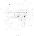
- the spring pin comprises a bolt 511 and a spring 512, and one end of the bolt 511 extends out of the screw connection part 56 into the connecting channel 41 under the action of the spring 512 to be in limited fitting with the pre-locking fitting surface 311 or in locking fitting with the locking fitting surface 312.
- a side wall of an end of the bolt 511 extending into the connecting channel 41 forms the pre-locking part 54.
- the bolt 511 is provided with a first limiting part 52
- the screw connection part 56 is provided with a limiting step 561 for limiting the first limiting part 52.
- the bolt 511 is prevented from falling out of the screw connection part 56 under the action of the spring 512 by the cooperation of the first limiting part 52 and the limiting step 561.
- the spring pin also comprises a positioning screw 55 in screw connection with the bolt 511.
- An end face of the positioning screw 55 forms the first limit part 52, and the end face of the positioning screw 55 is in limited fitting with the limiting step 561 on the screw connection part 56.
- the bolt 511 is also provided with a second limiting part 53, and an inner end face of the screw connection part 56 is in abutting fitting with the second limiting part 53.
- the screw connection part 56 drives the bolt 511 to move along the locking fitting surface 312 through the abutting fitting with the second limiting part 53 to lock the connection member 30 and the base 40.
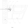
- the first component is a wall and the second component is a toilet body
- the mounting and dismounting process of the fixing device is briefly described as follows: Firstly, the connection member 30 is fixedly connected to the wall, and the base 40 is fixed on the toilet body 20.
- the spring pin (abutting member 51) is movably mounted in the threaded bushing (screw connection part 56) and partially extends out of the threaded bushing.
- the threaded bushing provided with the spring pin is screwed into the radial through hole 42 of the base 40, so that one end of the spring pin extends into the connecting channel 41.
- the toilet body 20 is moved towards the wall 10, so that the base 40 is in inserted fitting with the connection member 30 in an axial direction, allowing the connection member 30 to be inserted into the connecting channel 41 of the base 40 in the axial direction relative to the base 40.
- the pre-locking part 54 on the bolt 511 is not in limited fitting with the pre-locking fitting surface 311 on the connection member 30.
- the toilet body 20 is still moved towards the wall 10, so that the connection member 30 continues to be inserted into the connecting channel 41 of the base 40 in the axial direction, until the connection member 30 presses the spring pin (abutting member 51) to deform the spring pin, so that the pre-locking part 54 crosses the pre-locking fitting surface 311 (the first straight surface) of the connection member 30 to be in limited fitting with the pre-locking fitting surface 311; in this way, the base 40 will not be separated from the connection member 30, that is, the connection member 30 will not reversely retreat from the connecting channel 41, so that the toilet body can be hung by the pre-locking mechanism.
- the threaded bushing screw connection part 56
- an inner end face of the threaded bushing drives the spring pin to move along the locking fitting surface 312 (arc concave surface), so that the base 40 moves towards the wall, and then the wall and the toilet body are pressed close to each other, thus completing the locking of the toilet body.
- the toilet body can be dismounted simply by turning the threaded bushing in the reverse direction until the pre-locking part 54 (second straight surface) of the spring pin retreats from the connecting channel 41 of the base 40 instead of being in limited fitting with the pre-locking fitting surface 311 (first straight surface) of the connection member 30.
- the pre-locking mechanism is in the unlocking state, so that the connection member 30 can be detached from the base 40, thereby completing the dismounting of the toilet.
- the screw connection member is a screw
- the pre-locking part is arranged at one end of the screw
- the connection member is further provided with a movable pin and an elastic member
- the pre-locking fitting surface is formed on the movable pin.
- connection member 30 is further provided with a movable pin 57 and an elastic member 58
- the elastic member 58 is a compression spring and is arranged between the movable pin 57 and the connecting rod
- the pre-locking fitting surface 311 is formed on the movable pin 57
- the screw connection member is a screw 56'
- an end of the screw 56' extending into the connecting channel 41 is correspondingly provided with a limiting step 561, which forms the pre-locking part 54
- the movable pin 57 can reciprocate under the action of the elastic member 58 to enable the pre-locking fitting surface 311 to reciprocate between the unlocking position and the pre-locking position;
- the pre-locking fitting surface 311 abuts against the limiting step 561 for position limitation; and when the pre-locking mechanism is in the unlocking state, the pre-locking fitting
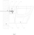
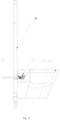
- a toilet is used as an example, it is assumed that the first component is a wall and the second component is a toilet body, and the mounting and dismounting process of the fixing device is briefly described as follows: As shown in Figs. 7 and 8 , in the initial state, the screw 56' of the locking mechanism 50 is screwed into the radial through hole 42 of the base 40, the movable pin 57 and the elastic member 58 are mounted in the connection member 30, and the movable pin 57 partially extends out of the connection member 30 under the spring force of the elastic member 58; the toilet body 20 is moved towards the wall 10, so that the base 40 is in inserted fitting with the connection member 30 in an axial direction, allowing the connection member 30 to be inserted into the connecting channel 41 of the base 40 in the axial direction relative to the base 40.
- the limiting step 561 (pre-locking part 54) on the screw 56' is not in limited fitting with the pre-locking fitting surface 311 on the movable pin 57.
- the toilet body 20 is still moved towards the wall 10, so that the connection member 30 continues to be inserted into the connecting channel 41 of the base 40 in the axial direction, until the screw 56' presses the movable pin 57 to deform the elastic member 58, and the pre-locking part 54 on the screw 56' crosses the pre-locking fitting surface 311 (the first straight surface) on the movable pin 57 to be in limited fitting with the pre-locking fitting surface 311; in this way, the base 40 will not be separated from the connection member 30, that is, the connection member 30 will not reversely retreat from the connecting channel 41, so that the toilet body can be hung by the pre-locking mechanism.
- the toilet body is caught by the connection member 30 and does not need to be held by a worker, the screw 56' can be rotated forward, an inner end face of the screw 56' moves along the locking fitting surface 312 (arc concave surface), so that the base 40 moves towards the wall, and then the wall and the toilet body are pressed close to each other, thus completing the locking of the toilet body.
- the screw 56' can be rotated forward, an inner end face of the screw 56' moves along the locking fitting surface 312 (arc concave surface), so that the base 40 moves towards the wall, and then the wall and the toilet body are pressed close to each other, thus completing the locking of the toilet body.
- the toilet can be dismounted simply by turning the screw 56' in the reverse direction until the pre-locking part 54 (second straight surface) of the screw 56' retreats from the connecting channel 41 of the base 40 instead of being in limited fitting with the pre-locking fitting surface 311 (first straight surface). At this point, the pre-locking mechanism is in the unlocking state, so that the connection member 30 can be detached from the base 40, thereby completing the dismounting of the toilet.
- the screw connection member is a screw
- the movable pin is replaced with a swing block.
- the movable pin 57 is replaced with a swing block (not shown), on which the pre-locking fitting surface 311 is formed, and the swing block is mounted on the connection member 30 in a swinging manner, and is in limited fitting with the limiting step 561 (pre-locking part 54) on the screw 56' during the insertion of the connection member 30 into the connecting channel 41.
- sanitary ware is provided.
- this embodiment also provides sanitary ware, which comprises the fixing device described in any one of the first, second and third embodiments above, wherein the first component 10 is a wall or a rack (as shown in Fig. 13 ), the second component 20 is a sanitary ware body, and the fixing device is used for fixedly connecting the body to the wall or the rack.
- the body is a toilet body, or the body may also be a washstand, a bathroom cabinet, a mop pool, etc., which is not limited here.
Landscapes
- Health & Medical Sciences (AREA)
- Life Sciences & Earth Sciences (AREA)
- Engineering & Computer Science (AREA)
- Hydrology & Water Resources (AREA)
- Public Health (AREA)
- Water Supply & Treatment (AREA)
- Connection Of Plates (AREA)
- Sanitary Device For Flush Toilet (AREA)
- Toilet Supplies (AREA)
Claims (7)
- Eine Befestigungsvorrichtung zur festen Verbindung eines ersten Bauteils (10) und eines zweiten Bauteils (20), wobei die Befestigungsvorrichtung ein Verbindungselement (30), das mit dem ersten Bauteil (10) verbunden ist, und eine Basis (40), die mit dem zweiten Bauteil (20) verbunden ist, umfasst, das Verbindungselement (30) ist so konfiguriert, dass es mittels eines Verriegelungsmechanismus (50) in einer Verriegelungsverbindung mit der Basis (40) steht, die Befestigungsvorrichtung umfasst weiterhin einen Vorverriegelungsmechanismus mit einem Vorverriegelungszustand und einem Entriegelungszustand; bevor der Verriegelungsmechanismus das Verbindungselement (30) und die Basis (40) verriegelt, befindet sich der Vorverriegelungsmechanismus im Vorverriegelungszustand, und das Verbindungselement (30) und die Basis (40) sind durch den Vorverriegelungsmechanismus in einer begrenzten Passung, um zu verhindern, dass das Verbindungselement (30) von der Basis (40) gelöst wird; und wenn sich der Vorverriegelungsmechanismus im Entriegelungszustand befindet, kann das Verbindungselement (30) von der Basis (40) gelöst werden, wobei das erste Bauteil (10) eine Wand oder ein Gestell ist, das zweite Bauteil (20) ein Gehäuse der Sanitärware ist; der Verriegelungsmechanismus (50) auf der Basis (40) angeordnet ist, und der Vorverriegelungsmechanismus eine Vorverriegelungs-Passfläche (311), die am Verbindungselement (30) angeordnet ist, und ein Vorverriegelungsteil (54) umfasst; die Vorverriegelungs-Passfläche (311) und/oder das Vorverriegelungsteil (54) zwischen einer Entriegelungsposition und einer Vorverriegelungsposition bewegt werden können; wenn sich der Vorverriegelungsmechanismus im Vorverriegelungszustand befindet, sind die Vorverriegelungs-Passfläche (311) und/oder das Vorverriegelungsteil (54) in der Vorverriegelungsposition, und die Vorverriegelungs-Passfläche (311) befindet sich in einer begrenzten Passung mit dem Vorverriegelungsteil (54), so dass das Verbindungselement (30) und die Basis (40) in begrenzter Passung sind; und wenn sich der Vorverriegelungsmechanismus im Entriegelungszustand befindet, sind die Vorverriegelungs-Passfläche (311) und/oder das Vorverriegelungsteil (54) in der Entriegelungsposition, und die Vorverriegelungs-Passfläche (311) ist vom Vorverriegelungsteil (54) getrennt, so dass das Verbindungselement (30) von der Basis (40) getrennt werden kann; wobei das Verbindungselement (30) zudem mit einer Verriegelungs-Passfläche (312) versehen ist, und der Verriegelungsmechanismus (50) das Verbindungselement (30) und die Basis (40) durch eine Verriegelungspassung mit der Verriegelungs-Passfläche (312) verbindet und verriegelt; das Verbindungselement (30) ist eine Verbindungsstange, die Basis (40) ist innen mit einem Verbindungskanal (41) versehen, in den die Verbindungsstange eingeführt wird, eine Seitenwand des Verbindungskanals (41) ist mit einem radialen Durchgangsloch (42) versehen, das mit dem Verbindungskanal (41) kommuniziert, und der Verriegelungsmechanismus (50) wird durch das radiale Durchgangsloch (42) in den Verbindungskanal eingeführt; und eine Seitenwand des Verbindungselements (30) ist mit einem konkaven Teil (31) versehen, und eine Oberfläche des konkaven Teils (31) bildet die Verriegelungs-Passfläche (312); der Verriegelungsmechanismus (50) ein Schraubverbindungselement in Schraubverbindung mit dem radialen Durchgangsloch (42) umfasst, und wenn das Schraubverbindungselement gedreht wird, befindet sich das Schraubverbindungselement in Verriegelungspassung mit der Verriegelungspassfläche (312);
dadurch gekennzeichnet, dass das Vorverriegelungsteil (54) auf dem Verriegelungsmechanismus (50) angeordnet ist. - Befestigungsvorrichtung nach Patentanspruch 1, wobei das Schraubverbindungselement ein Schraubverbindungsteil (56) und ein Druckelement (51) umfasst, das beweglich am Schraubverbindungsteil (56) angeordnet ist; das Vorverriegelungsteil (54) ist am Druckelement (51) angeordnet; und im Vorverriegelungszustand ist das Vorverriegelungsteil (54) am Druckelement (51) in begrenzter Passung mit der Vorverriegelungs-Passfläche (311), und wenn das Schraubverbindungsteil (56) gedreht wird, treibt das Schraubverbindungsteil (56) das Druckelement (51) an, so dass das Druckelement (51) in Verriegelungspassung mit der Verriegelungs-Passfläche (312) steht.
- Befestigungsvorrichtung nach Patentanspruch 2, wobei das Druckelement (51) ein Federstift oder ein Schwenkblock ist und das Schraubverbindungsteil (56) eine Gewindebuchse oder eine Schraube ist.
- Befestigungsvorrichtung nach Patentanspruch 3, wobei das Druckelement (51) ein Federstift ist, das Schraubverbindungsteil (56) ist eine Gewindebuchse, und der Federstift ist mit der Gewindebuchse ummantelt; der Federstift umfasst einen Bolzen (511) und eine Feder (512), und ein Ende des Bolzens (511) ragt aus dem Schraubverbindungsteil (56) in den Verbindungskanal (41) unter der Wirkung der Feder (512), um in begrenzter Passung mit der Vorverriegelungs-Passfläche (311) oder in Verriegelungspassung mit der VerriegelungsPassfläche (312) zu stehen; und eine Seitenwand eines Endes des Bolzens (511), das in den Verbindungskanal (41) ragt, bildet das Vorverriegelungsteil (54).
- Befestigungsvorrichtung nach Patentanspruch 1, wobei das Verbindungselement (30) zusätzlich mit einem beweglichen Stift und einem elastischen Element versehen ist, das elastische Element ist zwischen dem beweglichen Stift und der Verbindungsstange angeordnet, und die Vorverriegelungs-Passfläche (311) ist am beweglichen Stift ausgebildet; das Schraubverbindungselement ist eine Schraube (56'), und ein Ende der Schraube (56'), das in den Verbindungskanal (41) ragt, ist entsprechend mit einem Begrenzungsansatz versehen; der Begrenzungsansatz bildet das Vorverriegelungsteil (54); der bewegliche Stift kann unter der Wirkung des elastischen Elements hin- und herbewegen, so dass die Vorverriegelungs-Passfläche (311) zwischen der Entriegelungsposition und der Vorverriegelungsposition hin- und herbewegen kann; wenn sich der Vorverriegelungsmechanismus im Vorverriegelungszustand befindet, stößt die Vorverriegelungs-Passfläche (311) gegen den Begrenzungsansatz zur Positionsbegrenzung; und wenn sich der Vorverriegelungsmechanismus im Entriegelungszustand befindet, ist die Vorverriegelungs-Passfläche (311) vom Begrenzungsansatz getrennt.
- Befestigungsvorrichtung nach einem der Patentansprüche 1-5, wobei die Vorverriegelungs-Passfläche (311) eine erste gerade Fläche, das Vorverriegelungsteil (54) eine zweite gerade Fläche und die Verriegelungs-Passfläche (312) eine Bogenfläche oder eine gerade Fläche ist.
- Sanitärware, umfassend die Befestigungsvorrichtung nach einem der Patentansprüche 1-6, wobei das erste Bauteil (10) eine Wand oder ein Gestell ist, das zweite Bauteil (20) ein Gehäuse der Sanitärware ist und die Befestigungsvorrichtung verwendet wird, um das Gehäuse fest mit der Wand oder dem Gestell zu verbinden.
Applications Claiming Priority (2)
| Application Number | Priority Date | Filing Date | Title |
|---|---|---|---|
| CN201911008478.8A CN110670693B (zh) | 2019-10-22 | 2019-10-22 | 一种固定装置及带有该固定装置的卫浴设备 |
| PCT/CN2020/102672 WO2021077820A1 (zh) | 2019-10-22 | 2020-07-17 | 一种固定装置及带有该固定装置的卫浴设备 |
Publications (4)
| Publication Number | Publication Date |
|---|---|
| EP4023828A1 EP4023828A1 (de) | 2022-07-06 |
| EP4023828A4 EP4023828A4 (de) | 2022-11-09 |
| EP4023828B1 true EP4023828B1 (de) | 2025-01-01 |
| EP4023828C0 EP4023828C0 (de) | 2025-01-01 |
Family
ID=69083724
Family Applications (1)
| Application Number | Title | Priority Date | Filing Date |
|---|---|---|---|
| EP20878892.7A Active EP4023828B1 (de) | 2019-10-22 | 2020-07-17 | Befestigungsvorrichtung und sanitärgegenstand damit |
Country Status (5)
| Country | Link |
|---|---|
| EP (1) | EP4023828B1 (de) |
| CN (1) | CN110670693B (de) |
| ES (1) | ES3014397T3 (de) |
| PL (1) | PL4023828T3 (de) |
| WO (1) | WO2021077820A1 (de) |
Families Citing this family (2)
| Publication number | Priority date | Publication date | Assignee | Title |
|---|---|---|---|---|
| CN110670693B (zh) * | 2019-10-22 | 2025-01-14 | 厦门瑞尔特卫浴科技股份有限公司 | 一种固定装置及带有该固定装置的卫浴设备 |
| CN221321168U (zh) * | 2023-10-12 | 2024-07-12 | 厦门瑞尔特卫浴科技股份有限公司 | 一种马桶锁紧器的快装结构 |
Family Cites Families (13)
| Publication number | Priority date | Publication date | Assignee | Title |
|---|---|---|---|---|
| DE102013110966A1 (de) * | 2013-10-02 | 2015-04-02 | Fischer Italia S.R.L. | Befestiger für ein wandhängendes Objekt |
| DE102014013697A1 (de) * | 2014-09-17 | 2016-03-17 | Fischer Italia S.R.L. | Befestigungsvorrichtung zur Befestigung eines Sanitärobjekts |
| DE102014018978A1 (de) * | 2014-12-18 | 2016-06-23 | Fischer Italia S.R.L. | Befestigungsvorrichtung zur Befestigung eines Sanitärobjekts |
| DE102016103393A1 (de) * | 2016-02-26 | 2017-08-31 | Fischer Italia S.R.L. | Befestigungseinrichtung für ein wandhängendes Sanitärobjekt |
| CN206396855U (zh) * | 2016-12-06 | 2017-08-11 | 厦门瑞尔特卫浴科技股份有限公司 | 一种锁紧机构及带有锁紧机构的壁式马桶 |
| CN206745302U (zh) * | 2016-12-27 | 2017-12-15 | 海益(厦门)建材工业有限公司 | 一种具有预锁功能的锁紧机构 |
| CN206653329U (zh) * | 2017-03-17 | 2017-11-21 | 厦门瑞尔特卫浴科技股份有限公司 | 一种挂墙马桶的锁紧结构 |
| CN207032416U (zh) * | 2017-06-13 | 2018-02-23 | 海益(厦门)建材工业有限公司 | 一种壁挂式马桶锁紧装置 |
| EP3498926B1 (de) * | 2017-12-18 | 2019-11-27 | Xiamen R&J Precision Technology Co., Ltd. | Wandmontierte toilettenbefestigungsvorrichtung |
| CN209053195U (zh) * | 2018-09-30 | 2019-07-02 | 厦门纬图建材有限公司 | 坐便器锁紧件 |
| CN110206113B (zh) * | 2019-06-21 | 2024-07-12 | 厦门瑞尔特卫浴科技股份有限公司 | 一种马桶锁紧装置 |
| CN110670693B (zh) * | 2019-10-22 | 2025-01-14 | 厦门瑞尔特卫浴科技股份有限公司 | 一种固定装置及带有该固定装置的卫浴设备 |
| CN211816743U (zh) * | 2019-10-22 | 2020-10-30 | 厦门瑞尔特卫浴科技股份有限公司 | 一种固定装置及带有该固定装置的卫浴设备 |
-
2019
- 2019-10-22 CN CN201911008478.8A patent/CN110670693B/zh active Active
-
2020
- 2020-07-17 EP EP20878892.7A patent/EP4023828B1/de active Active
- 2020-07-17 ES ES20878892T patent/ES3014397T3/es active Active
- 2020-07-17 WO PCT/CN2020/102672 patent/WO2021077820A1/zh not_active Ceased
- 2020-07-17 PL PL20878892.7T patent/PL4023828T3/pl unknown
Also Published As
| Publication number | Publication date |
|---|---|
| EP4023828A1 (de) | 2022-07-06 |
| CN110670693B (zh) | 2025-01-14 |
| WO2021077820A1 (zh) | 2021-04-29 |
| ES3014397T3 (en) | 2025-04-22 |
| EP4023828C0 (de) | 2025-01-01 |
| EP4023828A4 (de) | 2022-11-09 |
| PL4023828T3 (pl) | 2025-05-12 |
| CN110670693A (zh) | 2020-01-10 |
Similar Documents
| Publication | Publication Date | Title |
|---|---|---|
| EP4023828B1 (de) | Befestigungsvorrichtung und sanitärgegenstand damit | |
| US8523126B2 (en) | Wall mountable accessory assembly | |
| US2937897A (en) | Backset link for lock sets | |
| CN108413135B (zh) | 一种管扣组件和刷圈水管固定结构 | |
| CN110206113B (zh) | 一种马桶锁紧装置 | |
| CN214143980U (zh) | 一种安装结构、安装模块及挂墙式便器 | |
| EP4244437B1 (de) | Verbesserte befestigungsvorrichtung für wandhängende toiletten | |
| CN212001466U (zh) | 一种新型固定装置及具有该新型固定装置的卫浴设备 | |
| CN210621870U (zh) | 一种马桶锁紧装置 | |
| CN208503664U (zh) | 一种管扣组件和刷圈水管固定结构 | |
| CN212772685U (zh) | 一种固定装置及具有其的卫浴设备 | |
| JP5228351B2 (ja) | 手洗装置 | |
| CN214884154U (zh) | 一种超薄面板 | |
| CN212507808U (zh) | 一种无接触式公共厕所门用锁及应用其的公共厕所门 | |
| CN212294933U (zh) | 一种马桶的泵安装结构 | |
| CN208941969U (zh) | 马桶用盖板与陶瓷体的拉索式快拆安装连接总成 | |
| CN218622445U (zh) | 一种龙头按压下水器 | |
| CN219048204U (zh) | 一种卫浴挂件 | |
| CN222045365U (zh) | 一种卫生间弹销式门锁 | |
| KR0121443Y1 (ko) | 좌변기 시트 개방장치 | |
| KR200165467Y1 (ko) | 세면대 및 좌변기용 밸브 | |
| CN115450288A (zh) | 一种龙头按压下水器 | |
| CN217294432U (zh) | 一种可折叠的卫生间 | |
| CN223281891U (zh) | 一种飞机卫生间用柜门锁 | |
| KR200296649Y1 (ko) | 세면기 거치대 |
Legal Events
| Date | Code | Title | Description |
|---|---|---|---|
| STAA | Information on the status of an ep patent application or granted ep patent |
Free format text: STATUS: THE INTERNATIONAL PUBLICATION HAS BEEN MADE |
|
| PUAI | Public reference made under article 153(3) epc to a published international application that has entered the european phase |
Free format text: ORIGINAL CODE: 0009012 |
|
| STAA | Information on the status of an ep patent application or granted ep patent |
Free format text: STATUS: REQUEST FOR EXAMINATION WAS MADE |
|
| 17P | Request for examination filed |
Effective date: 20220331 |
|
| AK | Designated contracting states |
Kind code of ref document: A1 Designated state(s): AL AT BE BG CH CY CZ DE DK EE ES FI FR GB GR HR HU IE IS IT LI LT LU LV MC MK MT NL NO PL PT RO RS SE SI SK SM TR |
|
| STAA | Information on the status of an ep patent application or granted ep patent |
Free format text: STATUS: EXAMINATION IS IN PROGRESS |
|
| A4 | Supplementary search report drawn up and despatched |
Effective date: 20221007 |
|
| RIC1 | Information provided on ipc code assigned before grant |
Ipc: F16B 21/16 20060101ALN20220930BHEP Ipc: F16B 21/12 20060101ALN20220930BHEP Ipc: E03D 11/14 20060101AFI20220930BHEP |
|
| 17Q | First examination report despatched |
Effective date: 20221020 |
|
| DAV | Request for validation of the european patent (deleted) | ||
| DAX | Request for extension of the european patent (deleted) | ||
| GRAP | Despatch of communication of intention to grant a patent |
Free format text: ORIGINAL CODE: EPIDOSNIGR1 |
|
| STAA | Information on the status of an ep patent application or granted ep patent |
Free format text: STATUS: GRANT OF PATENT IS INTENDED |
|
| RIC1 | Information provided on ipc code assigned before grant |
Ipc: F16B 21/16 20060101ALN20240626BHEP Ipc: F16B 21/12 20060101ALN20240626BHEP Ipc: E03D 11/14 20060101AFI20240626BHEP |
|
| INTG | Intention to grant announced |
Effective date: 20240704 |
|
| GRAS | Grant fee paid |
Free format text: ORIGINAL CODE: EPIDOSNIGR3 |
|
| GRAA | (expected) grant |
Free format text: ORIGINAL CODE: 0009210 |
|
| STAA | Information on the status of an ep patent application or granted ep patent |
Free format text: STATUS: THE PATENT HAS BEEN GRANTED |
|
| AK | Designated contracting states |
Kind code of ref document: B1 Designated state(s): AL AT BE BG CH CY CZ DE DK EE ES FI FR GB GR HR HU IE IS IT LI LT LU LV MC MK MT NL NO PL PT RO RS SE SI SK SM TR |
|
| REG | Reference to a national code |
Ref country code: GB Ref legal event code: FG4D |
|
| REG | Reference to a national code |
Ref country code: CH Ref legal event code: EP |
|
| REG | Reference to a national code |
Ref country code: DE Ref legal event code: R096 Ref document number: 602020044281 Country of ref document: DE |
|
| REG | Reference to a national code |
Ref country code: IE Ref legal event code: FG4D |
|
| U01 | Request for unitary effect filed |
Effective date: 20250120 |
|
| U07 | Unitary effect registered |
Designated state(s): AT BE BG DE DK EE FI FR IT LT LU LV MT NL PT RO SE SI Effective date: 20250127 |
|
| REG | Reference to a national code |
Ref country code: ES Ref legal event code: FG2A Ref document number: 3014397 Country of ref document: ES Kind code of ref document: T3 Effective date: 20250422 |
|
| PG25 | Lapsed in a contracting state [announced via postgrant information from national office to epo] |
Ref country code: IS Free format text: LAPSE BECAUSE OF FAILURE TO SUBMIT A TRANSLATION OF THE DESCRIPTION OR TO PAY THE FEE WITHIN THE PRESCRIBED TIME-LIMIT Effective date: 20250501 Ref country code: NO Free format text: LAPSE BECAUSE OF FAILURE TO SUBMIT A TRANSLATION OF THE DESCRIPTION OR TO PAY THE FEE WITHIN THE PRESCRIBED TIME-LIMIT Effective date: 20250401 |
|
| PG25 | Lapsed in a contracting state [announced via postgrant information from national office to epo] |
Ref country code: HR Free format text: LAPSE BECAUSE OF FAILURE TO SUBMIT A TRANSLATION OF THE DESCRIPTION OR TO PAY THE FEE WITHIN THE PRESCRIBED TIME-LIMIT Effective date: 20250101 |
|
| PG25 | Lapsed in a contracting state [announced via postgrant information from national office to epo] |
Ref country code: GR Free format text: LAPSE BECAUSE OF FAILURE TO SUBMIT A TRANSLATION OF THE DESCRIPTION OR TO PAY THE FEE WITHIN THE PRESCRIBED TIME-LIMIT Effective date: 20250402 |
|
| PG25 | Lapsed in a contracting state [announced via postgrant information from national office to epo] |
Ref country code: CZ Free format text: LAPSE BECAUSE OF FAILURE TO SUBMIT A TRANSLATION OF THE DESCRIPTION OR TO PAY THE FEE WITHIN THE PRESCRIBED TIME-LIMIT Effective date: 20250101 |
|
| U20 | Renewal fee for the european patent with unitary effect paid |
Year of fee payment: 6 Effective date: 20250707 |
|
| PG25 | Lapsed in a contracting state [announced via postgrant information from national office to epo] |
Ref country code: SM Free format text: LAPSE BECAUSE OF FAILURE TO SUBMIT A TRANSLATION OF THE DESCRIPTION OR TO PAY THE FEE WITHIN THE PRESCRIBED TIME-LIMIT Effective date: 20250101 |
|
| PGFP | Annual fee paid to national office [announced via postgrant information from national office to epo] |
Ref country code: ES Payment date: 20250808 Year of fee payment: 6 |
|
| PGFP | Annual fee paid to national office [announced via postgrant information from national office to epo] |
Ref country code: PL Payment date: 20250704 Year of fee payment: 6 Ref country code: TR Payment date: 20250717 Year of fee payment: 6 |
|
| PGFP | Annual fee paid to national office [announced via postgrant information from national office to epo] |
Ref country code: GB Payment date: 20250710 Year of fee payment: 6 |
|
| PG25 | Lapsed in a contracting state [announced via postgrant information from national office to epo] |
Ref country code: SK Free format text: LAPSE BECAUSE OF FAILURE TO SUBMIT A TRANSLATION OF THE DESCRIPTION OR TO PAY THE FEE WITHIN THE PRESCRIBED TIME-LIMIT Effective date: 20250101 |
|
| PLBE | No opposition filed within time limit |
Free format text: ORIGINAL CODE: 0009261 |
|
| STAA | Information on the status of an ep patent application or granted ep patent |
Free format text: STATUS: NO OPPOSITION FILED WITHIN TIME LIMIT |