EP4244437B1 - Verbesserte befestigungsvorrichtung für wandhängende toiletten - Google Patents
Verbesserte befestigungsvorrichtung für wandhängende toiletten Download PDFInfo
- Publication number
- EP4244437B1 EP4244437B1 EP21892456.1A EP21892456A EP4244437B1 EP 4244437 B1 EP4244437 B1 EP 4244437B1 EP 21892456 A EP21892456 A EP 21892456A EP 4244437 B1 EP4244437 B1 EP 4244437B1
- Authority
- EP
- European Patent Office
- Prior art keywords
- fixing device
- adjustment
- fixing
- clamping body
- lower body
- Prior art date
- Legal status (The legal status is an assumption and is not a legal conclusion. Google has not performed a legal analysis and makes no representation as to the accuracy of the status listed.)
- Active
Links
Images


Classifications
-
- E—FIXED CONSTRUCTIONS
- E03—WATER SUPPLY; SEWERAGE
- E03D—WATER-CLOSETS OR URINALS WITH FLUSHING DEVICES; FLUSHING VALVES THEREFOR
- E03D11/00—Other component parts of water-closets, e.g. noise-reducing means in the flushing system, flushing pipes mounted in the bowl, seals for the bowl outlet, devices preventing overflow of the bowl contents; devices forming a water seal in the bowl after flushing, devices eliminating obstructions in the bowl outlet or preventing backflow of water and excrements from the waterpipe
- E03D11/13—Parts or details of bowls; Special adaptations of pipe joints or couplings for use with bowls, e.g. provisions in bowl construction preventing backflow of waste-water from the bowl in the flushing pipe or cistern, provisions for a secondary flushing, for noise-reducing
- E03D11/14—Means for connecting the bowl to the wall, e.g. to a wall outlet
-
- E—FIXED CONSTRUCTIONS
- E03—WATER SUPPLY; SEWERAGE
- E03C—DOMESTIC PLUMBING INSTALLATIONS FOR FRESH WATER OR WASTE WATER; SINKS
- E03C1/00—Domestic plumbing installations for fresh water or waste water; Sinks
- E03C1/12—Plumbing installations for waste water; Basins or fountains connected thereto; Sinks
- E03C1/32—Holders or supports for basins
- E03C1/322—Holders or supports for basins connected to the wall only
Definitions
- the present invention relates to a fixing device according to the preamble of claim 1, for anchoring a wall-hung toilet and similar sanitary furniture item to a wall, which provides a practical, fast and durable connection.
- Suspended sanitary fixtures have been used for many years. These sanitary facilities are supported, generally hidden in the sanitary facility, on holding elements which are fastened in a cantilever manner on a supporting wall so that the sanitary facility does not stand on the floor.
- a fixing mount is used with an affixing stud fastened on the wall, and the fixing mount is fastened on the wall, at the desired position, by means of an adjustment member therein.
- wall-hung toilets which is advantageous for the user in terms of hygiene due to the lack of contact with the ground. It is also preferred by the users for easy cleaning. Since the wall-hung toilets/water closets do not have contact with the ground, it is expected that the fixing devices thereof are more durable.
- Document DE2252970A1 shows a fixing device comprising two wedge elements sliding on each other by turning a screw being connected to one of the wedge elements. Another fixing device is disclosed in DE9103333U1 .
- An object of the present invention is to provide a fixing device that enables solving the problems described above and existing in the prior art.
- Another object of the present invention is to provide a fixing device that provides a robust and durable connection, which avoids any possible wobbling and oscillation.
- Another object of the present invention is to provide a fixing device wherein the water closet can be connected to the wall through the closet cover assembly holes without requiring the fixing holes that must be drilled on the sides of the sanitary furniture items, while it is facilitated to remove the rear inner side of the closet - in a fully empty state - in the production of the water closets, reducing the cost and increasing the production efficiency.
- Still another object of the present invention is to provide a fixing device in which the need for assembly holes is eliminated that is very difficult to drill in the wall-hung toilets made of ceramic material.
- the present invention relates a fixing device according to claim 1, for fixing a sanitary furniture item, said fixing device comprising a clamping body for attaching against an inner wall of the sanitary furniture item; an adjustment member and an adjustment housing for inserting the adjustment member into the clamping body for adjustment purposes; a lower body arranged to be coupled with an affixing stud mounted on a wall; and a fixing member arranged to pass through an assembly hole of the sanitary furniture item and to be fixed in a through-hole in the clamping body.
- Said fixing device comprises an upper contact surface on the lower body that is inclined with respect to a longitudinal axis of the fixing device.
- said clamping body is positioned to slide on the inclined upper contact surface; and the lower body comprises an inclined adjustment surface on which an adjustment member lower end is slidably moved by rotating said adjustment member in the adjustment housing.
- the present invention also proposes a sanitary furniture item comprising said fixing device.
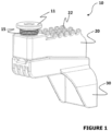
- the fixing device (10) presented within the scope of the present invention is arranged to be used in sanitary furniture items (100).
- the fixing device (10) is specially arranged to use for connecting wall-hung toilets -especially for hung sanitary fittings- to a wall and a built-in reservoir.
- the present invention relates a fixing device (10) for fixing a sanitary furniture item (100), said fixing device (10) comprising a clamping body (20) for attaching against an inner wall (102) of the sanitary furniture item (100); an adjustment member (13) and an adjustment housing (24) for inserting the adjustment member (13) into the clamping body (20) for adjustment purposes; a lower body (30) arranged to be coupled with an affixing stud (50) mounted on a wall; and a fixing member (11) arranged to pass through an assembly hole (101) of the sanitary furniture item (100) and to be fixed in a through-hole (15) in the clamping body (20).
- the upper surface of the engagement protrusion (32) that is to be contacted with the engagement channel (23) has a larger cross-section.
- the upper surface of the engagement channel (23) also has a larger cross-section and provides a more robust engagement. In addition, it limits the movement of the clamping body (20) in an upward and downward direction.
- the clamping body (20) has a plurality of abutment protrusions (22) arranged at the same height and at certain intervals of the clamping body (20).
- the abutment protrusions (22) in the form of rounded protrusions abut on the inner wall (102) of the sanitary furniture item (100) to which it will be attached.
- the inner wall (102) is preferably inside the uppermost end, when in use.
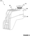
- the fixing device (10) mainly comprises two main parts, the first one of which is the lower body (30), which is to be securely held by the affixing stud (50) in the form of a worm gear that is connected to the wall, and the other one is the clamping body (20) that is partially moved on the adjustment surface (33) on the lower body (30).
- the fixing device (10) When the user desires to use the fixing device (10), (s)he first places the adjustment member (13) into the appropriate adjustment member housing (24) in the clamping body (20). Then, the female engagement channel (23) and the male engagement protrusion (32) slides over each other so that the lower body (30) and the clamping body (20) are connected to each other. In this way, an optimum linear movement is obtained.
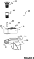
- suitable fixing members (11) are passed through the assembly holes (101) on the sanitary furniture item (100) and are fixed to the sanitary furniture item (100) by being passed through a through-hole (15) in the clamping body (20).
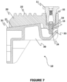
- a cylindrical and partially threaded retaining member (12) can be used to be fitted into the through-hole (15) on the clamping body (20) in order to install the sanitary furniture item (100) in an easier manner. As illustrated in Fig. 6 , the retaining member (12) is connected to the clamping body (20) and is adjusted to correspond to the appropriate assembly holes.
- the affixing stud (50) is first passed through the lower body (30), followed by a sub-assembly of a nut (52) and preferably a washer (51). Thereafter, said retaining member (12) is removed from the through-hole (15) where it is located, and the fixing member (11) is inserted into this hole in order to complete the fixing process.
- the through-hole (15) there are teeth housings so as to be engaged by the teeth of the fixing member (11).
- the fixing member (11) When the fixing member (11) is in use, it has a wide hole that extends along its middle portion so as to allow access to the adjustment member (13).
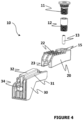
- the adjustment member (13) is rotated in its housing in the direction of compression by means of a suitable rotation apparatus in order to pull the sanitary furniture item (100) towards the wall and prevent it from wobbling.
- a suitable Allen key is first passed through the fixing member (11) and then into the adjustment member (13).
- the adjustment member lower end (14) forming an end portion of the adjustment member (13) contacts the inclined adjustment surface (33) in the lower body (30).
- the adjustment member lower end (14) moves on the adjustment surface (33), and the sanitary furniture item (100) is pulled towards the wall and tightened against it with a sliding movement of the clamping body (20).
- the sanitary furniture item (100) is securely connected and possible vibrations, any play resulting from a possible gap are prevented.
- Said sanitary furniture item (100) disclosed within the scope of the invention may be a wall-hung toilet.
Landscapes
- Engineering & Computer Science (AREA)
- Health & Medical Sciences (AREA)
- Life Sciences & Earth Sciences (AREA)
- Hydrology & Water Resources (AREA)
- Public Health (AREA)
- Water Supply & Treatment (AREA)
- Environmental & Geological Engineering (AREA)
- Connection Of Plates (AREA)
- Snaps, Bayonet Connections, Set Pins, And Snap Rings (AREA)
- Standing Axle, Rod, Or Tube Structures Coupled By Welding, Adhesion, Or Deposition (AREA)
Claims (14)
- Eine Befestigungsvorrichtung (10) zur Befestigung eines Sanitärmöbels (100), z. B. einer wandhängenden Toilette, wobei die Befestigungsvorrichtung (10) folgendes umfasst:einen Klemmkörper (20) zum Anbringen an einer Innenwand (102) des Sanitärmöbels (100);ein Einstellelement (13); ein Einstellgehäuse (24) des Klemmkörpers zum Einsetzen des Einstellelements (13) in den Klemmkörper (20) zu Einstellzwecken;einen unteren Körper (30), der so angeordnet ist, dass er mit einem an einer Wand montierten Befestigungsstift (50) verbunden werden kann;ein Befestigungselement (11), das so angeordnet ist, dass es durch ein Montageloch (101) des Sanitärmöbels (100) geführt und in einem Durchgangsloch (15) im Klemmkörper (20) befestigt werden kann;eine obere Kontaktfläche (31) am unteren Körper (30), die in Bezug auf eine Längsachse der Befestigungsvorrichtung (X) geneigt ist, wobeider Klemmkörper (20) so positioniert ist, dass er auf der geneigten oberen Kontaktfläche (31) gleitet, dadurch gekennzeichnet, dass der untere Körper (30) eine geneigte Einstellfläche (33) umfasst, auf der ein unteres Ende (14) des Einstellelements (13) durch Drehen des Einstellelements (13) in dem Einstellgehäuse (24) gleitend bewegt wird.
- Befestigungsvorrichtung (10) nach Anspruch 1, wobei die Einstellfläche (33) des unteren Körpers (30) mit einem Winkel (α1) von 30° bis 60° relativ zur Längsachse der Befestigungsvorrichtung (X) geneigt und mit dem unteren Körper (30) integriert ist.
- Befestigungsvorrichtung (10) nach Anspruch 1 oder 2, wobei der untere Körper (30) die obere Kontaktfläche (31) aufweist, die mit einem Winkel (a2) von 15° bis 30° relativ zur Längsachse der Befestigungsvorrichtung (X) geneigt ist und einen oberen Teil des unteren Körpers (30) bildet.
- Befestigungsvorrichtung (10) nach einem der vorhergehenden Ansprüche, wobei der untere Körper (30) einen Eingriffsvorsprung (32) an der oberen Kontaktfläche (31) aufweist, der sich entlang der Längsachse der oberen Kontaktfläche (31) als Vorsprung erstreckt.
- Eine Befestigungsvorrichtung (10) nach Anspruch 4, wobei der Klemmkörper (20) einen Eingriffskanal (23) umfasst, der am Boden des Klemmkörpers (20) ausgebildet ist, wobei der Eingriffskanal (23) entsprechend dem Eingriffsvorsprung (32) geformt und bemessen ist und dem Klemmkörper (20) eine lineare Bewegung in einer geneigten Weise ermöglicht.
- Eine Befestigungsvorrichtung (10) nach Anspruch 5, wobei die obere Fläche des Eingriffsvorsprungs (32), die mit dem Eingriffskanal (23) in Kontakt gebracht werden soll, einen größeren Querschnitt aufweist als der Boden des Eingriffsvorsprungs (32).
- Befestigungsvorrichtung (10) nach einem der vorhergehenden Ansprüche, wobei der Klemmkörper (20) eine Vielzahl von Anschlagvorsprüngen (22) aufweist, die auf gleicher Höhe und in einem bestimmten Abstand zueinander angeordnet sind.
- Befestigungsvorrichtung (10) nach einem der vorhergehenden Ansprüche, wobei das Einstellelement (13) eine Stellschraube ist, die durch Drehen im Uhrzeigersinn mit einem geeigneten Inbusschlüssel festgezogen werden kann.
- Eine Befestigungsvorrichtung (10) nach einem der vorhergehenden Ansprüche, wobei das Durchgangsloch (15) Zahnaufnahmen aufweist, um mit den Zähnen des Befestigungselements (11) in Eingriff zu kommen.
- Eine Befestigungsvorrichtung (10) nach einem der vorhergehenden Ansprüche, wobei der untere Körper (30) ein Bolzenloch (34), durch das der Befestigungsbolzen (50) zu führen ist, und eine Mutter (52) zur Befestigung des Befestigungsbolzens (50) aufweist.
- Eine Befestigungsvorrichtung (10) nach einem der vorhergehenden Ansprüche, wobei das Befestigungselement (11) ein inneres Loch aufweist, das im Gebrauch den Zugang zum Einstellelement (13) ermöglicht.
- Sanitärmöbel (100) mit Befestigungsvorrichtung (10) nach einem der vorhergehenden Ansprüche, mit mindestens zwei Montagelöchern (101) auf der Oberseite (103) des Sanitärmöbels (100).
- Sanitäres Möbelstück (100) nach Anspruch 12, umfassend zwei Befestigungsvorrichtungen (10), wobei jedes Montageloch mit einer jeweiligen Befestigungsvorrichtung in Verbindung steht.
- Sanitäres Möbelstück (100) nach Anspruch 12 oder 13, das eine wandhängende Toilette ist.
Applications Claiming Priority (2)
| Application Number | Priority Date | Filing Date | Title |
|---|---|---|---|
| TR2020/18330A TR202018330A2 (tr) | 2020-11-16 | 2020-11-16 | Asma klozetlerde kullanılmak üzere geliştirilmiş bir bağlantı tertibatı. |
| PCT/TR2021/050160 WO2022103353A1 (en) | 2020-11-16 | 2021-02-19 | An improved fixing device for wall-hung toilets |
Publications (4)
| Publication Number | Publication Date |
|---|---|
| EP4244437A1 EP4244437A1 (de) | 2023-09-20 |
| EP4244437A4 EP4244437A4 (de) | 2024-04-24 |
| EP4244437C0 EP4244437C0 (de) | 2024-10-23 |
| EP4244437B1 true EP4244437B1 (de) | 2024-10-23 |
Family
ID=77689263
Family Applications (1)
| Application Number | Title | Priority Date | Filing Date |
|---|---|---|---|
| EP21892456.1A Active EP4244437B1 (de) | 2020-11-16 | 2021-02-19 | Verbesserte befestigungsvorrichtung für wandhängende toiletten |
Country Status (3)
| Country | Link |
|---|---|
| EP (1) | EP4244437B1 (de) |
| TR (1) | TR202018330A2 (de) |
| WO (1) | WO2022103353A1 (de) |
Families Citing this family (2)
| Publication number | Priority date | Publication date | Assignee | Title |
|---|---|---|---|---|
| US20240360657A1 (en) * | 2023-04-14 | 2024-10-31 | Kohler India Corporation Private Limited | Installation arrangement for a toilet system |
| CH720786A2 (de) * | 2023-05-16 | 2024-11-29 | Laufen Schweiz Ag | Wandbefestigung für Sanitärartikel und Sanitärartikel mit einer Wandbefestigung |
Family Cites Families (7)
| Publication number | Priority date | Publication date | Assignee | Title |
|---|---|---|---|---|
| SE360898B (de) * | 1971-11-05 | 1973-10-08 | Ifoe Ab | |
| DE9103333U1 (de) * | 1991-03-19 | 1991-06-20 | Keramag Keramische Werke Ag, 4030 Ratingen | Vorrichtung zur Befestigung von sanitärkeramischen Gegenständen |
| NL9401071A (nl) * | 1994-06-28 | 1996-02-01 | Koninkl Sphinx Nv | Montagesamenstel voor een wandclosetpot. |
| EP2876222B1 (de) * | 2013-11-20 | 2020-03-11 | TECE GmbH | Einheit umfassend eine Befestigungsvorrichtung für ein hängendes WC und ein Halteelement. |
| DE102016117717A1 (de) * | 2016-09-20 | 2018-03-22 | Fischer Italia S.R.L. | Befestigungseinrichtung für ein wandhängendes Sanitärobjekt, Befestigungsanordnung und Verfahren zur Montage eines wandhängenden Sanitärobjekts |
| DE102018105161A1 (de) * | 2017-04-10 | 2018-10-11 | Fischer Italia S.R.L. | Befestigungsvorrichtung und Befestigungsanordnung |
| US10851534B2 (en) * | 2018-04-12 | 2020-12-01 | Watts Regulator Co. | Wall hung toilet assembly with a sloped gasket |
-
2020
- 2020-11-16 TR TR2020/18330A patent/TR202018330A2/tr unknown
-
2021
- 2021-02-19 WO PCT/TR2021/050160 patent/WO2022103353A1/en not_active Ceased
- 2021-02-19 EP EP21892456.1A patent/EP4244437B1/de active Active
Also Published As
| Publication number | Publication date |
|---|---|
| TR202018330A2 (tr) | 2021-06-21 |
| EP4244437C0 (de) | 2024-10-23 |
| WO2022103353A1 (en) | 2022-05-19 |
| EP4244437A4 (de) | 2024-04-24 |
| EP4244437A1 (de) | 2023-09-20 |
Similar Documents
| Publication | Publication Date | Title |
|---|---|---|
| EP4244437B1 (de) | Verbesserte befestigungsvorrichtung für wandhängende toiletten | |
| US8104726B2 (en) | Bath fixture mounting system | |
| US8523126B2 (en) | Wall mountable accessory assembly | |
| CN111432688B (zh) | 用于安装在两个基本平行的表面之间的张力安装杆 | |
| US5026013A (en) | Support post mounting assembly | |
| KR102249951B1 (ko) | 건축용 발코니 난간의 핸드레일 고정장치 | |
| EP3926112B1 (de) | Befestigungshalterung zur verankerung von halterahmen von sanitäreinrichtungen an mauerwerk | |
| CN101668904A (zh) | 用于固定壁装式的物体的装置 | |
| CN101418649A (zh) | 一种把手组件 | |
| US6007285A (en) | Cantilever fastener assembly | |
| KR101847740B1 (ko) | 기둥 및 이를 위한 기둥 고정 장치 | |
| EP2644791A1 (de) | Sanitäre Einrichtung und verdeckte Befestigung für eine derartige sanitäre Einrichtung | |
| US7611108B2 (en) | Sanitary element system with a system interface | |
| EP4023828A1 (de) | Befestigungsvorrichtung und sanitärgegenstand damit | |
| EP1655418A2 (de) | Befestigungsvorrichtung für die Wandmontage von einer Sanitärgegenstandinstallationsstruktur | |
| KR20160129534A (ko) | 칸막이용 받침대 | |
| EP4190985B1 (de) | Höhenverstellbare quadratische aussenabdeckung mit eingebautem zylinder | |
| WO2004090350A1 (en) | Pound-in glide for an article of furniture | |
| GB2371481A (en) | Shower unit and riser rail assembly | |
| US20060043039A1 (en) | Integrated posts/ferrule | |
| KR200237568Y1 (ko) | 가구 설치용 앵커볼트 | |
| KR200151565Y1 (ko) | 건축물 외장석재의 고정구 | |
| CN219147423U (zh) | 一种可伸缩的淋浴房 | |
| KR102813472B1 (ko) | 간격조절이 용이한 수건 걸이대 | |
| CN219306289U (zh) | 一种可调的浴室柜暗装装置 |
Legal Events
| Date | Code | Title | Description |
|---|---|---|---|
| STAA | Information on the status of an ep patent application or granted ep patent |
Free format text: STATUS: THE INTERNATIONAL PUBLICATION HAS BEEN MADE |
|
| PUAI | Public reference made under article 153(3) epc to a published international application that has entered the european phase |
Free format text: ORIGINAL CODE: 0009012 |
|
| STAA | Information on the status of an ep patent application or granted ep patent |
Free format text: STATUS: REQUEST FOR EXAMINATION WAS MADE |
|
| 17P | Request for examination filed |
Effective date: 20230329 |
|
| AK | Designated contracting states |
Kind code of ref document: A1 Designated state(s): AL AT BE BG CH CY CZ DE DK EE ES FI FR GB GR HR HU IE IS IT LI LT LU LV MC MK MT NL NO PL PT RO RS SE SI SK SM TR |
|
| DAV | Request for validation of the european patent (deleted) | ||
| DAX | Request for extension of the european patent (deleted) | ||
| A4 | Supplementary search report drawn up and despatched |
Effective date: 20240326 |
|
| RIC1 | Information provided on ipc code assigned before grant |
Ipc: E03C 1/322 20060101ALI20240320BHEP Ipc: E03D 11/14 20060101AFI20240320BHEP |
|
| GRAP | Despatch of communication of intention to grant a patent |
Free format text: ORIGINAL CODE: EPIDOSNIGR1 |
|
| STAA | Information on the status of an ep patent application or granted ep patent |
Free format text: STATUS: GRANT OF PATENT IS INTENDED |
|
| GRAS | Grant fee paid |
Free format text: ORIGINAL CODE: EPIDOSNIGR3 |
|
| INTG | Intention to grant announced |
Effective date: 20240819 |
|
| GRAA | (expected) grant |
Free format text: ORIGINAL CODE: 0009210 |
|
| STAA | Information on the status of an ep patent application or granted ep patent |
Free format text: STATUS: THE PATENT HAS BEEN GRANTED |
|
| AK | Designated contracting states |
Kind code of ref document: B1 Designated state(s): AL AT BE BG CH CY CZ DE DK EE ES FI FR GB GR HR HU IE IS IT LI LT LU LV MC MK MT NL NO PL PT RO RS SE SI SK SM TR |
|
| REG | Reference to a national code |
Ref country code: GB Ref legal event code: FG4D |
|
| REG | Reference to a national code |
Ref country code: CH Ref legal event code: EP |
|
| REG | Reference to a national code |
Ref country code: DE Ref legal event code: R096 Ref document number: 602021020827 Country of ref document: DE |
|
| REG | Reference to a national code |
Ref country code: IE Ref legal event code: FG4D |
|
| U01 | Request for unitary effect filed |
Effective date: 20241024 |
|
| U07 | Unitary effect registered |
Designated state(s): AT BE BG DE DK EE FI FR IT LT LU LV MT NL PT RO SE SI Effective date: 20241120 |
|
| U20 | Renewal fee for the european patent with unitary effect paid |
Year of fee payment: 5 Effective date: 20250109 |
|
| PG25 | Lapsed in a contracting state [announced via postgrant information from national office to epo] |
Ref country code: IS Free format text: LAPSE BECAUSE OF FAILURE TO SUBMIT A TRANSLATION OF THE DESCRIPTION OR TO PAY THE FEE WITHIN THE PRESCRIBED TIME-LIMIT Effective date: 20250223 Ref country code: HR Free format text: LAPSE BECAUSE OF FAILURE TO SUBMIT A TRANSLATION OF THE DESCRIPTION OR TO PAY THE FEE WITHIN THE PRESCRIBED TIME-LIMIT Effective date: 20241023 |
|
| PG25 | Lapsed in a contracting state [announced via postgrant information from national office to epo] |
Ref country code: ES Free format text: LAPSE BECAUSE OF FAILURE TO SUBMIT A TRANSLATION OF THE DESCRIPTION OR TO PAY THE FEE WITHIN THE PRESCRIBED TIME-LIMIT Effective date: 20241023 |
|
| PG25 | Lapsed in a contracting state [announced via postgrant information from national office to epo] |
Ref country code: NO Free format text: LAPSE BECAUSE OF FAILURE TO SUBMIT A TRANSLATION OF THE DESCRIPTION OR TO PAY THE FEE WITHIN THE PRESCRIBED TIME-LIMIT Effective date: 20250123 |
|
| PG25 | Lapsed in a contracting state [announced via postgrant information from national office to epo] |
Ref country code: GR Free format text: LAPSE BECAUSE OF FAILURE TO SUBMIT A TRANSLATION OF THE DESCRIPTION OR TO PAY THE FEE WITHIN THE PRESCRIBED TIME-LIMIT Effective date: 20250124 |
|
| PG25 | Lapsed in a contracting state [announced via postgrant information from national office to epo] |
Ref country code: PL Free format text: LAPSE BECAUSE OF FAILURE TO SUBMIT A TRANSLATION OF THE DESCRIPTION OR TO PAY THE FEE WITHIN THE PRESCRIBED TIME-LIMIT Effective date: 20241023 |
|
| PG25 | Lapsed in a contracting state [announced via postgrant information from national office to epo] |
Ref country code: RS Free format text: LAPSE BECAUSE OF FAILURE TO SUBMIT A TRANSLATION OF THE DESCRIPTION OR TO PAY THE FEE WITHIN THE PRESCRIBED TIME-LIMIT Effective date: 20250123 |
|
| PG25 | Lapsed in a contracting state [announced via postgrant information from national office to epo] |
Ref country code: SM Free format text: LAPSE BECAUSE OF FAILURE TO SUBMIT A TRANSLATION OF THE DESCRIPTION OR TO PAY THE FEE WITHIN THE PRESCRIBED TIME-LIMIT Effective date: 20241023 |
|
| PG25 | Lapsed in a contracting state [announced via postgrant information from national office to epo] |
Ref country code: SK Free format text: LAPSE BECAUSE OF FAILURE TO SUBMIT A TRANSLATION OF THE DESCRIPTION OR TO PAY THE FEE WITHIN THE PRESCRIBED TIME-LIMIT Effective date: 20241023 |
|
| PG25 | Lapsed in a contracting state [announced via postgrant information from national office to epo] |
Ref country code: CZ Free format text: LAPSE BECAUSE OF FAILURE TO SUBMIT A TRANSLATION OF THE DESCRIPTION OR TO PAY THE FEE WITHIN THE PRESCRIBED TIME-LIMIT Effective date: 20241023 |
|
| PLBE | No opposition filed within time limit |
Free format text: ORIGINAL CODE: 0009261 |
|
| STAA | Information on the status of an ep patent application or granted ep patent |
Free format text: STATUS: NO OPPOSITION FILED WITHIN TIME LIMIT |
|
| PG25 | Lapsed in a contracting state [announced via postgrant information from national office to epo] |
Ref country code: MC Free format text: LAPSE BECAUSE OF FAILURE TO SUBMIT A TRANSLATION OF THE DESCRIPTION OR TO PAY THE FEE WITHIN THE PRESCRIBED TIME-LIMIT Effective date: 20241023 |
|
| REG | Reference to a national code |
Ref country code: CH Ref legal event code: PL |
|
| 26N | No opposition filed |
Effective date: 20250724 |
|
| PG25 | Lapsed in a contracting state [announced via postgrant information from national office to epo] |
Ref country code: CH Free format text: LAPSE BECAUSE OF NON-PAYMENT OF DUE FEES Effective date: 20250228 |
|
| GBPC | Gb: european patent ceased through non-payment of renewal fee |
Effective date: 20250219 |