EP4023482A1 - Monitoring method and device for determination of gear stick position, vehicle control unit, and vehicle - Google Patents
Monitoring method and device for determination of gear stick position, vehicle control unit, and vehicle Download PDFInfo
- Publication number
- EP4023482A1 EP4023482A1 EP20906776.8A EP20906776A EP4023482A1 EP 4023482 A1 EP4023482 A1 EP 4023482A1 EP 20906776 A EP20906776 A EP 20906776A EP 4023482 A1 EP4023482 A1 EP 4023482A1
- Authority
- EP
- European Patent Office
- Prior art keywords
- gear
- stick position
- acceptable
- stick
- actual
- Prior art date
- Legal status (The legal status is an assumption and is not a legal conclusion. Google has not performed a legal analysis and makes no representation as to the accuracy of the status listed.)
- Pending
Links
- 238000012544 monitoring process Methods 0.000 title claims abstract description 55
- 238000000034 method Methods 0.000 title claims abstract description 26
- 239000002346 layers by function Substances 0.000 claims abstract description 47
- 238000012806 monitoring device Methods 0.000 claims description 16
- 230000007935 neutral effect Effects 0.000 claims description 8
- 239000010410 layer Substances 0.000 description 28
- 230000000994 depressogenic effect Effects 0.000 description 9
- 238000005516 engineering process Methods 0.000 description 7
- 230000008901 benefit Effects 0.000 description 5
- 238000010586 diagram Methods 0.000 description 4
- 230000003287 optical effect Effects 0.000 description 3
- 230000007547 defect Effects 0.000 description 2
- 230000006870 function Effects 0.000 description 2
- 230000005540 biological transmission Effects 0.000 description 1
- 210000004556 brain Anatomy 0.000 description 1
- 230000008859 change Effects 0.000 description 1
- 239000000446 fuel Substances 0.000 description 1
- 230000002452 interceptive effect Effects 0.000 description 1
- 238000012986 modification Methods 0.000 description 1
- 230000004048 modification Effects 0.000 description 1
- 230000008439 repair process Effects 0.000 description 1
- 230000003068 static effect Effects 0.000 description 1
- 238000006467 substitution reaction Methods 0.000 description 1
Images

Classifications
-
- F—MECHANICAL ENGINEERING; LIGHTING; HEATING; WEAPONS; BLASTING
- F16—ENGINEERING ELEMENTS AND UNITS; GENERAL MEASURES FOR PRODUCING AND MAINTAINING EFFECTIVE FUNCTIONING OF MACHINES OR INSTALLATIONS; THERMAL INSULATION IN GENERAL
- F16H—GEARING
- F16H61/00—Control functions within control units of change-speed- or reversing-gearings for conveying rotary motion ; Control of exclusively fluid gearing, friction gearing, gearings with endless flexible members or other particular types of gearing
- F16H61/12—Detecting malfunction or potential malfunction, e.g. fail safe; Circumventing or fixing failures
-
- B—PERFORMING OPERATIONS; TRANSPORTING
- B60—VEHICLES IN GENERAL
- B60L—PROPULSION OF ELECTRICALLY-PROPELLED VEHICLES; SUPPLYING ELECTRIC POWER FOR AUXILIARY EQUIPMENT OF ELECTRICALLY-PROPELLED VEHICLES; ELECTRODYNAMIC BRAKE SYSTEMS FOR VEHICLES IN GENERAL; MAGNETIC SUSPENSION OR LEVITATION FOR VEHICLES; MONITORING OPERATING VARIABLES OF ELECTRICALLY-PROPELLED VEHICLES; ELECTRIC SAFETY DEVICES FOR ELECTRICALLY-PROPELLED VEHICLES
- B60L3/00—Electric devices on electrically-propelled vehicles for safety purposes; Monitoring operating variables, e.g. speed, deceleration or energy consumption
-
- B—PERFORMING OPERATIONS; TRANSPORTING
- B60—VEHICLES IN GENERAL
- B60L—PROPULSION OF ELECTRICALLY-PROPELLED VEHICLES; SUPPLYING ELECTRIC POWER FOR AUXILIARY EQUIPMENT OF ELECTRICALLY-PROPELLED VEHICLES; ELECTRODYNAMIC BRAKE SYSTEMS FOR VEHICLES IN GENERAL; MAGNETIC SUSPENSION OR LEVITATION FOR VEHICLES; MONITORING OPERATING VARIABLES OF ELECTRICALLY-PROPELLED VEHICLES; ELECTRIC SAFETY DEVICES FOR ELECTRICALLY-PROPELLED VEHICLES
- B60L15/00—Methods, circuits, or devices for controlling the traction-motor speed of electrically-propelled vehicles
- B60L15/20—Methods, circuits, or devices for controlling the traction-motor speed of electrically-propelled vehicles for control of the vehicle or its driving motor to achieve a desired performance, e.g. speed, torque, programmed variation of speed
- B60L15/2054—Methods, circuits, or devices for controlling the traction-motor speed of electrically-propelled vehicles for control of the vehicle or its driving motor to achieve a desired performance, e.g. speed, torque, programmed variation of speed by controlling transmissions or clutches
-
- B—PERFORMING OPERATIONS; TRANSPORTING
- B60—VEHICLES IN GENERAL
- B60L—PROPULSION OF ELECTRICALLY-PROPELLED VEHICLES; SUPPLYING ELECTRIC POWER FOR AUXILIARY EQUIPMENT OF ELECTRICALLY-PROPELLED VEHICLES; ELECTRODYNAMIC BRAKE SYSTEMS FOR VEHICLES IN GENERAL; MAGNETIC SUSPENSION OR LEVITATION FOR VEHICLES; MONITORING OPERATING VARIABLES OF ELECTRICALLY-PROPELLED VEHICLES; ELECTRIC SAFETY DEVICES FOR ELECTRICALLY-PROPELLED VEHICLES
- B60L3/00—Electric devices on electrically-propelled vehicles for safety purposes; Monitoring operating variables, e.g. speed, deceleration or energy consumption
- B60L3/0092—Electric devices on electrically-propelled vehicles for safety purposes; Monitoring operating variables, e.g. speed, deceleration or energy consumption with use of redundant elements for safety purposes
-
- B—PERFORMING OPERATIONS; TRANSPORTING
- B60—VEHICLES IN GENERAL
- B60L—PROPULSION OF ELECTRICALLY-PROPELLED VEHICLES; SUPPLYING ELECTRIC POWER FOR AUXILIARY EQUIPMENT OF ELECTRICALLY-PROPELLED VEHICLES; ELECTRODYNAMIC BRAKE SYSTEMS FOR VEHICLES IN GENERAL; MAGNETIC SUSPENSION OR LEVITATION FOR VEHICLES; MONITORING OPERATING VARIABLES OF ELECTRICALLY-PROPELLED VEHICLES; ELECTRIC SAFETY DEVICES FOR ELECTRICALLY-PROPELLED VEHICLES
- B60L3/00—Electric devices on electrically-propelled vehicles for safety purposes; Monitoring operating variables, e.g. speed, deceleration or energy consumption
- B60L3/12—Recording operating variables ; Monitoring of operating variables
-
- F—MECHANICAL ENGINEERING; LIGHTING; HEATING; WEAPONS; BLASTING
- F16—ENGINEERING ELEMENTS AND UNITS; GENERAL MEASURES FOR PRODUCING AND MAINTAINING EFFECTIVE FUNCTIONING OF MACHINES OR INSTALLATIONS; THERMAL INSULATION IN GENERAL
- F16H—GEARING
- F16H59/00—Control inputs to control units of change-speed-, or reversing-gearings for conveying rotary motion
- F16H59/02—Selector apparatus
- F16H59/04—Ratio selector apparatus
- F16H59/044—Ratio selector apparatus consisting of electrical switches or sensors
-
- F—MECHANICAL ENGINEERING; LIGHTING; HEATING; WEAPONS; BLASTING
- F16—ENGINEERING ELEMENTS AND UNITS; GENERAL MEASURES FOR PRODUCING AND MAINTAINING EFFECTIVE FUNCTIONING OF MACHINES OR INSTALLATIONS; THERMAL INSULATION IN GENERAL
- F16H—GEARING
- F16H59/00—Control inputs to control units of change-speed-, or reversing-gearings for conveying rotary motion
- F16H59/68—Inputs being a function of gearing status
- F16H59/70—Inputs being a function of gearing status dependent on the ratio established
-
- G—PHYSICS
- G06—COMPUTING; CALCULATING OR COUNTING
- G06F—ELECTRIC DIGITAL DATA PROCESSING
- G06F9/00—Arrangements for program control, e.g. control units
- G06F9/06—Arrangements for program control, e.g. control units using stored programs, i.e. using an internal store of processing equipment to receive or retain programs
-
- B—PERFORMING OPERATIONS; TRANSPORTING
- B60—VEHICLES IN GENERAL
- B60L—PROPULSION OF ELECTRICALLY-PROPELLED VEHICLES; SUPPLYING ELECTRIC POWER FOR AUXILIARY EQUIPMENT OF ELECTRICALLY-PROPELLED VEHICLES; ELECTRODYNAMIC BRAKE SYSTEMS FOR VEHICLES IN GENERAL; MAGNETIC SUSPENSION OR LEVITATION FOR VEHICLES; MONITORING OPERATING VARIABLES OF ELECTRICALLY-PROPELLED VEHICLES; ELECTRIC SAFETY DEVICES FOR ELECTRICALLY-PROPELLED VEHICLES
- B60L2240/00—Control parameters of input or output; Target parameters
- B60L2240/10—Vehicle control parameters
- B60L2240/12—Speed
-
- B—PERFORMING OPERATIONS; TRANSPORTING
- B60—VEHICLES IN GENERAL
- B60L—PROPULSION OF ELECTRICALLY-PROPELLED VEHICLES; SUPPLYING ELECTRIC POWER FOR AUXILIARY EQUIPMENT OF ELECTRICALLY-PROPELLED VEHICLES; ELECTRODYNAMIC BRAKE SYSTEMS FOR VEHICLES IN GENERAL; MAGNETIC SUSPENSION OR LEVITATION FOR VEHICLES; MONITORING OPERATING VARIABLES OF ELECTRICALLY-PROPELLED VEHICLES; ELECTRIC SAFETY DEVICES FOR ELECTRICALLY-PROPELLED VEHICLES
- B60L2240/00—Control parameters of input or output; Target parameters
- B60L2240/40—Drive Train control parameters
- B60L2240/42—Drive Train control parameters related to electric machines
- B60L2240/423—Torque
-
- B—PERFORMING OPERATIONS; TRANSPORTING
- B60—VEHICLES IN GENERAL
- B60L—PROPULSION OF ELECTRICALLY-PROPELLED VEHICLES; SUPPLYING ELECTRIC POWER FOR AUXILIARY EQUIPMENT OF ELECTRICALLY-PROPELLED VEHICLES; ELECTRODYNAMIC BRAKE SYSTEMS FOR VEHICLES IN GENERAL; MAGNETIC SUSPENSION OR LEVITATION FOR VEHICLES; MONITORING OPERATING VARIABLES OF ELECTRICALLY-PROPELLED VEHICLES; ELECTRIC SAFETY DEVICES FOR ELECTRICALLY-PROPELLED VEHICLES
- B60L2250/00—Driver interactions
- B60L2250/24—Driver interactions by lever actuation
-
- B—PERFORMING OPERATIONS; TRANSPORTING
- B60—VEHICLES IN GENERAL
- B60L—PROPULSION OF ELECTRICALLY-PROPELLED VEHICLES; SUPPLYING ELECTRIC POWER FOR AUXILIARY EQUIPMENT OF ELECTRICALLY-PROPELLED VEHICLES; ELECTRODYNAMIC BRAKE SYSTEMS FOR VEHICLES IN GENERAL; MAGNETIC SUSPENSION OR LEVITATION FOR VEHICLES; MONITORING OPERATING VARIABLES OF ELECTRICALLY-PROPELLED VEHICLES; ELECTRIC SAFETY DEVICES FOR ELECTRICALLY-PROPELLED VEHICLES
- B60L2260/00—Operating Modes
- B60L2260/20—Drive modes; Transition between modes
- B60L2260/26—Transition between different drive modes
-
- B—PERFORMING OPERATIONS; TRANSPORTING
- B60—VEHICLES IN GENERAL
- B60Y—INDEXING SCHEME RELATING TO ASPECTS CROSS-CUTTING VEHICLE TECHNOLOGY
- B60Y2200/00—Type of vehicle
- B60Y2200/90—Vehicles comprising electric prime movers
- B60Y2200/91—Electric vehicles
-
- F—MECHANICAL ENGINEERING; LIGHTING; HEATING; WEAPONS; BLASTING
- F16—ENGINEERING ELEMENTS AND UNITS; GENERAL MEASURES FOR PRODUCING AND MAINTAINING EFFECTIVE FUNCTIONING OF MACHINES OR INSTALLATIONS; THERMAL INSULATION IN GENERAL
- F16H—GEARING
- F16H59/00—Control inputs to control units of change-speed-, or reversing-gearings for conveying rotary motion
- F16H59/68—Inputs being a function of gearing status
- F16H59/70—Inputs being a function of gearing status dependent on the ratio established
- F16H2059/706—Monitoring gear ratio in stepped transmissions, e.g. by calculating the ratio from input and output speed
-
- F—MECHANICAL ENGINEERING; LIGHTING; HEATING; WEAPONS; BLASTING
- F16—ENGINEERING ELEMENTS AND UNITS; GENERAL MEASURES FOR PRODUCING AND MAINTAINING EFFECTIVE FUNCTIONING OF MACHINES OR INSTALLATIONS; THERMAL INSULATION IN GENERAL
- F16H—GEARING
- F16H61/00—Control functions within control units of change-speed- or reversing-gearings for conveying rotary motion ; Control of exclusively fluid gearing, friction gearing, gearings with endless flexible members or other particular types of gearing
- F16H61/12—Detecting malfunction or potential malfunction, e.g. fail safe; Circumventing or fixing failures
- F16H2061/1208—Detecting malfunction or potential malfunction, e.g. fail safe; Circumventing or fixing failures with diagnostic check cycles; Monitoring of failures
-
- F—MECHANICAL ENGINEERING; LIGHTING; HEATING; WEAPONS; BLASTING
- F16—ENGINEERING ELEMENTS AND UNITS; GENERAL MEASURES FOR PRODUCING AND MAINTAINING EFFECTIVE FUNCTIONING OF MACHINES OR INSTALLATIONS; THERMAL INSULATION IN GENERAL
- F16H—GEARING
- F16H61/00—Control functions within control units of change-speed- or reversing-gearings for conveying rotary motion ; Control of exclusively fluid gearing, friction gearing, gearings with endless flexible members or other particular types of gearing
- F16H61/12—Detecting malfunction or potential malfunction, e.g. fail safe; Circumventing or fixing failures
- F16H2061/1232—Bringing the control into a predefined state, e.g. giving priority to particular actuators or gear ratios
-
- F—MECHANICAL ENGINEERING; LIGHTING; HEATING; WEAPONS; BLASTING
- F16—ENGINEERING ELEMENTS AND UNITS; GENERAL MEASURES FOR PRODUCING AND MAINTAINING EFFECTIVE FUNCTIONING OF MACHINES OR INSTALLATIONS; THERMAL INSULATION IN GENERAL
- F16H—GEARING
- F16H61/00—Control functions within control units of change-speed- or reversing-gearings for conveying rotary motion ; Control of exclusively fluid gearing, friction gearing, gearings with endless flexible members or other particular types of gearing
- F16H61/12—Detecting malfunction or potential malfunction, e.g. fail safe; Circumventing or fixing failures
- F16H2061/124—Limiting the input power, torque or speed
Definitions
- the present application relates to the field of vehicle technology, and in particular, to a monitoring method and device for determination of a gear-stick position, a vehicle controller, and a vehicle.
- the vehicle controller for a pure electric vehicle as a control brain of the whole vehicle is closely related to the functions of the whole vehicle. Different from the traditional fuel vehicle, the functions of which are completed by a transmission controller, the determination of the gear-stick position of the pure electric vehicle is calculated by the vehicle controller.
- the functional layer of the vehicle controller determines, according to a gear signal, an actual gear-stick position and an acceptable gear-stick position selected by a driver, and executes a torque request according to the consistency between the actual gear-stick position and the acceptable gear-stick position.
- an objective of the present application is to provide a monitoring method for determination of a gear-stick position, aiming to solve the defect in the existing technologies that no corresponding monitoring strategies is provided for the to-be-shifted gear-stick position and the acceptable gear-stick position calculated by the functional layer of the vehicle controller.
- a monitoring method for determination of a gear-stick position includes the following steps: obtaining a first actual gear-stick position and a first acceptable gear-stick position calculated by a functional layer; calculating a second actual gear-stick position according to a gear-stick position signal; determining whether the first actual gear-stick position and the second actual gear-stick position are consistent; determining whether the first acceptable gear-stick position is valid in case that the first actual gear-stick position and the second actual gear-stick position are consistent; and controlling a vehicle to enter a safe state in case that the first actual gear-stick position and the second actual gear-stick position are inconsistent, or the first acceptable gear-stick position is invalid.
- the step of controlling a vehicle to enter a safe state includes determining whether a current speed of the vehicle is greater than a first threshold. In case that the current speed of the vehicle is greater than the first threshold, the vehicle is controlled to remain driving at the acceptable gear-stick position currently being executed, and a limit torque is set for the acceptable gear-stick position currently being executed; and in case that the current speed of the vehicle is smaller than or equal to the first threshold, the vehicle is controlled to travel in neutral gear.
- the gear-stick position signal includes a positive gear-stick position signal and a negative gear-stick position signal
- the step of calculating a second actual gear-stick position according to a gear-stick position signal includes determining whether the positive gear-stick position signal and the negative gear-stick position signal are consistent.
- the monitoring method for determination of a gear-stick position also includes controlling the vehicle to enter the safe state in case that the positive gear-stick position signal and the negative gear-stick position signal are inconsistent.
- the step of determining whether the first acceptable gear-stick position is valid includes the following steps: determining whether the acceptable gear-stick position currently being executed can be shifted to the first acceptable gear-stick position in case that the first actual gear-stick position and the first acceptable gear-stick position are consistent; and in case of determining that the acceptable gear-stick position currently being executed cannot be shifted to the first acceptable gear-stick position, then it is determined that the first acceptable gear-stick position is invalid.
- the steps also includes determining whether the acceptable gear-stick position currently being executed can be shifted to the first actual gear-stick position in case that the first actual gear-stick position and the first acceptable gear-stick position are inconsistent; and in case of determining that the acceptable gear-stick position currently being executed can be shifted to the first actual gear-stick position, it is determined that the first acceptable gear-stick position is invalid.
- the monitoring method for determination of a gear-stick position described in the present application has the following advantages:
- the monitoring method for determination of a gear-stick position described in the present application can monitor the first actual gear-stick position and the first acceptable gear-stick position calculated by the functional layer, and in case that the first actual gear-stick position calculated by the functional layer and the second gear-stick position calculated by itself are inconsistent, or the first acceptable gear-stick position is invalid, the vehicle is controlled to enter the safe state, such that the safe driving of the whole vehicle can be ensured.
- Another objective of the present application is to provide a monitoring device for determination of a gear-stick position, so as to solve the defect in the existing technologies that no corresponding monitoring strategies is provided for the to-be-shifted gear-stick position and the acceptable gear-stick position calculated by the functional layer of the vehicle controller.
- a monitoring device for determination of a gear-stick position includes: an acquisition module, a calculation module, a first determination module, a second determination module, and a control module.
- the acquisition module is configured to acquire a first actual gear-stick position and a first acceptable gear-stick position calculated by a functional layer.
- the calculation module is configured to calculate a second actual gear-stick position according to a gear-stick position signal.
- the first determination module is configured to determine whether the first actual gear-stick position and the second actual gear-stick position are consistent.
- the second determination module is configured to determine, in case that the first actual gear-stick position and the second actual gear-stick position are consistent, whether the first acceptable gear-stick position is valid.
- the control module is configured to control, in case that the first actual gear-stick position and the second actual gear-stick position are inconsistent, or the first acceptable gear-stick position is invalid, a vehicle to enter a safe state.
- control module is configured to control the vehicle to enter the safe state according to the following operations that include: determining whether a current speed of the vehicle is greater than a first threshold; in case that the current speed is greater than the first threshold, controlling the vehicle to remain driving at the acceptable gear-stick position currently being executed, and setting a limit torque for the acceptable gear-stick position currently being executed; and in case that the current speed is lesser than or equal to the first threshold, controlling the vehicle to travel in neutral gear.
- the gear-stick position signal includes a positive gear-stick position signal and a negative gear-stick position signal.
- the calculation module is configured to calculate the second actual gear-stick position according to the gear lever position signal based on the following operations that include: determining whether the positive gear-stick position signal and the negative gear-stick position signal are consistent; and in case that the positive gear-stick position signal and the negative gear-stick position signal are consistent, calculating the second actual gear-stick position.
- the control module is also configured to control, in case that the positive gear-stick position signal and the negative gear-stick position signal are inconsistent, the vehicle to enter the safe state.
- the second determination module is configured to determine whether the first acceptable gear-stick position is valid according to the following operations that include: in case that the first actual gear-stick position and the first acceptable gear-stick position are consistent, performing the following operations: determining whether the acceptable gear-stick position currently being executed can be shifted to the first acceptable gear-stick position; and in case of determining that the acceptable gear-stick position currently being executed cannot be shifted to the first acceptable gear-stick position, then it is determined that the first acceptable gear-stick position is invalid.
- the operations also includes: determining whether the acceptable gear-stick position currently being executed can be shifted to the first actual gear-stick position; and in case of determining that the acceptable gear-stick position currently being executed can be shifted to the first actual gear-stick position, then it is determined that the first acceptable gear-stick position is invalid.
- the monitoring device for determination of a gear-stick position and the above-described monitoring method for determination of a gear-stick position have the same advantages over the existing technologies, which will not be repeated herein.
- a vehicle controller which includes the above-described monitoring device for determination of a gear-stick position.
- a vehicle which includes the vehicle controller as described above.
- a machine-readable storage medium in which, a program is stored, and the program, when being executed, causes the above-described monitoring method for determination of a gear-stick position to be implemented.
- actual gear-stick position referred to means a target gear-stick position shifted from the current gear-stick position by a driver
- acceptable gear-stick position means a next acceptable gear-stick position that, under the condition of ensuring vehicle safety, can be shifted from the currently executing acceptable gear-stick position, calculated according to the vehicle state, speed, actual gear-stick position and the like.
- the actual gear-stick position and acceptable gear-stick position described in the embodiments of the present application may include, for example, P gear (parking gear), D gear (drive gear), R gear (reverse gear), N gear (neutral gear) and the like.
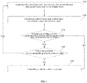
- FIG. 1 shows a schematic flow diagram of a monitoring method for determination of a gear-stick position according to an embodiment of the present application.
- the embodiment of the present application provides a monitoring method for determining the gear-stick position, the method may be performed through a vehicle controller, specifically, through a monitoring layer of the vehicle controller.
- the monitoring layer may be configured to monitor a functional layer of the vehicle controller, the functional layer is configured to perform the determination of the gear-stick position.
- the vehicle controller may, for example, be a vehicle controller of a pure electric vehicle.
- the method may include steps S110 to step S150.
- step S110 a first actual gear-stick position and a first acceptable gear-stick position calculated by the functional layer are acquired.
- a sensor may be arranged at a position of the gear stick located to detect the gear-stick position.
- the electronic shifter of a vehicle can collect a gear-stick position signal detected by the sensor and provide the gear-stick position signal to the vehicle controller through via bus.
- two gear-stick position signals are detected, which may be, for example, a positive gear-stick position signal and a negative gear-stick position signal.
- the two sensors can detect changes in the gear-stick position, and generate a positive gear-stick position signal and a negative gear-stick position signal
- the positive and negative gear-stick position signals can be transmitted to the electronic shifter, and through the electronic shifter, the positive and negative gear-stick position signals can be provided to the vehicle controller via the bus.
- the functional layer of the vehicle controller can calculate the first actual gear-stick position according to the positive and negative gear-stick position signals.
- the functional layer may also calculate the first acceptable gear-stick position according to a vehicle state, a current speed and the calculated first actual gear-stick position. Specifically, the functional layer may be configured to determine whether the conditions for shifting from the acceptable gear-stick position currently being executed to the first acceptable gear-stick position are satisfied, if satisfied, the first acceptable gear-stick position may be determined to be the first actual gear-stick position, if not satisfied, the first acceptable gear-stick position is determined to be the acceptable gear-stick position currently being executed.
- the functional layer in the absence of logic failures, may be configured to calculate the first actual gear-stick position D gear.
- the functional layer may also be configured to determine whether the conditions for shifting from the currently executing acceptable gear-stick position N gear to the first actual gear-stick position D gear are met, i.e., whether the brake pedal has been stepped on.
- the conditions for shifting from the currently executing acceptable gear-stick position N gear to the first actual gear-stick position D gear may be determined to be met, and then the first acceptable gear-stick position may be determined to be D gear, otherwise, the first acceptable gear-stick position may be determined to be N gear.
- step S120 a second actual gear-stick position is calculated based on a gear-stick position signal.
- the monitoring layer may also be configured to calculate the second actual gear-stick position accordingly according to the gear-stick position signal.
- the gear-stick position signal may include two gear-stick position signals, i.e., the positive gear-stick position signal and the negative gear-stick position signal.
- the monitoring layer may be configured to first determine whether the positive and negative gear-stick position signals are consistent. For example, a gear-stick position may be calculated according to the positive gear-stick position signal, a gear-stick position may be calculated according to the negative gear-stick position signal, and if the calculated two gear-stick positions are consistent, then the positive gear-stick position signal and the negative gear-stick position signal are consistent. Otherwise, it may be considered that the positive gear-stick position signal and the negative gear-stick position signal are inconsistent, and if the positive gear-stick position signal and the negative gear-stick position signal are inconsistent, the vehicle may be controlled to enter a safe state.
- the actual gear-stick position determined according to either gear-stick position signal is determined as the second actual gear-stick position.
- step S130 it is determined whether the first actual gear-stick position and the second actual gear-stick position are consistent.
- step S140 it is determined whether the first acceptable gear-stick position is valid, in case that the first actual gear-stick position and the second actual gear-stick position are consistent.
- the first actual gear-stick position and the second actual gear-stick position are consistent, indicating that the logic of the functional layer for calculating the actual gear-stick position is faultless, and can continue to judge whether the first acceptable gear-stick position determined by the functional layer is valid. In case that a logical failure is existed in the logic of the functional layer for calculating the actual gear-stick position, the first actual gear-stick position and the second actual gear-stick position will be inconsistent.
- the monitoring layer may be configured to determine whether the acceptable gear-stick position currently being executed can be shifted to the first acceptable gear-stick position, i.e., to determine, according to the vehicle state and/or the current speed and the like, whether the condition for shifting are satisfied. If it is determined that the acceptable gear-stick position currently being executed cannot be shifted to the first acceptable gear-stick position, then the first acceptable gear-stick position may be determined to be invalid. If it is determined that the acceptable gear-stick position currently being executed can be shifted to the first acceptable gear-stick position, then the first acceptable gear-stick position may be determined to be valid.
- the monitoring layer may be configured to determine whether the acceptable gear-stick position currently being executed can be shifted to the first actual gear-stick position, that is, to determine, according to the vehicle state and/or the current speed and the like, whether the condition for shifting are satisfied. If it is determined that the acceptable gear-stick position currently being executed can be shifted to the first actual gear-stick position, then the first acceptable gear-stick position may be determined to be invalid. If it is determined that the acceptable gear-stick position currently being executed cannot be shifted to the first actual gear-stick position, then the first acceptable gear-stick position may be determined to be valid.
- the first actual gear-stick position calculated by the functional layer is D gear. Because when shifting from N gear to D gear, the operation needs to be performed at the same time is to press the brake pedal.
- the functional layer correspondingly detects whether the brake pedal is stepped on, if the brake pedal is depressed, the functional layer may determine that the gear-stick position can be shifted from N gear to D gear at present, and calculate the first acceptable gear-stick position as D gear. If the functional layer detects that the brake pedal has not been stepped on, then it is determined that the gear-stick position cannot be shifted from N gear to D gear at present, and then the acceptable gear-stick position N gear currently being executed is determined as the first acceptable gear-stick position.
- the calculated first actual gear-stick position is D gear
- the calculated first acceptable gear-stick position is D gear
- the monitoring layer first calculates the second actual gear-stick position D gear, and determines that the first actual gear-stick position and the second actual gear-stick position are consistent. The monitoring layer then calculates whether the first acceptable gear-stick position is valid.
- the execution condition for the monitoring layer to first determine that the currently executing acceptable gear-stick position N gear is shifted to the first acceptable gear-stick position D gear is that the brake pedal is depressed, then the monitoring layer monitors whether the brake pedal is depressed. As previously assumed, the driver does not step on the brake pedal, then the monitoring layer can determine that the currently executing acceptable gear-stick position N gear cannot be shifted to the first acceptable gear-stick position D gear, it thus can be determined that the first acceptable gear-stick position is invalid.
- the calculated first actual gear-stick position is D gear
- the calculated first acceptable gear-stick position is N gear.
- the monitoring layer first calculates the second actual gear-stick position D gear, and determines that the first actual gear-stick position and the second actual gear-stick position are consistent. The monitoring layer then calculates whether the first acceptable gear-stick position is valid.
- the execution condition for the monitoring layer to first determine that the currently executing acceptable gear-stick position N gear is shifted to the first actual gear-stick position D gear is that the brake pedal is depressed, then the monitoring layer monitors whether the brake pedal is depressed. As previously assumed, the brake pedal is depressed, then the monitoring layer can determine that the currently executing acceptable gear-stick position N gear can be shifted to the first acceptable gear-stick position D gear, that is, the first acceptable gear-stick position should be D gear, and the first acceptable gear-stick position determined by the monitoring layer is N gear, therefore, it thus can be determined that the first acceptable gear-stick position is invalid.
- the condition for shifting from D gear to R gear may be that the speed cannot exceed a preset value
- the monitoring layer may be configured to monitor whether the first acceptable gear-stick position calculated by the functional layer is valid according to this condition.
- step S150 the vehicle is controlled to enter a safe state in case that the first actual gear-stick position and the second actual gear-stick position are inconsistent or the first acceptable gear-stick position is invalid.
- the monitoring layer determines that the first acceptable gear-stick position is valid, then continue to acquire the first actual gear-stick position and the first acceptable gear-stick position calculated by the functional layer next time without interfering with the execution of the functional layer.
- the monitoring layer determines that the first actual gear-stick position and the second actual gear-stick position are inconsistent, or determines that the first acceptable gear-stick position is invalid, or as described above, the monitoring layer determines that the positive gear-stick position signal and the negative gear-stick position signal are inconsistent, that is, the monitoring layer determines that the functional layer has logic failure, then the monitoring layer can control the vehicle to enter the safe state to ensure safe driving of the whole vehicle.
- the vehicle may be controlled according to the current speed of the vehicle to enter the safe state.
- the current speed of the vehicle can be obtained by bus.
- the monitoring layer may be configured to determine whether the current speed of the vehicle is greater than a first threshold.
- the first threshold can be set to any appropriate value based on the actual situation.
- the gear position should not be directly set to neutral gear, and the vehicle may be controlled to remain driving at the acceptable gear-stick position currently being executed.
- the currently executing acceptable gear position is D gear
- the driver's target gear position is R gear
- the current speed is greater than the first threshold.
- the monitoring layer determines that the functional layer has logic failure, and the vehicle needs to be controlled to enter the safe state, then the vehicle can be controlled to remain driving in D gear.
- the functional layer may also set a limit torque for the acceptable gear-stick position currently being executed to control the vehicle to reduce the speed. It will be appreciated that the limit torque corresponding to different gears may be the same or different, or the limit torque is less than the requested torque of the gear in the case of no fault, for example, the limit torque may be half of the requested torque of the gear under normal circumstances.
- the gear position can be set directly to the neutral gear (e.g., N gear) to slow down the vehicle to a standstill.
- the vehicle controller may also issue a prompt about the vehicle failure, for example, the prompt may eventually be presented to the driver in a form that is observable by the driver, in order to facilitate the driver to repair the vehicle and the like.
- the logic processing results of the functional layer of the vehicle controller are monitored, and in the case of functional layer failure, the vehicle is controlled to enter the safe state, thereby ensuring the safety of the whole vehicle.
- FIG. 2 shows a block diagram of a monitoring device for determination of a gear-stick position according to an embodiment of the present application.
- the embodiment of the present application also provides a monitoring device for determination of a gear-stick position
- the device may be disposed on a vehicle controller, for example, may form the monitoring layer of the vehicle controller.
- the monitoring layer may be configured to monitor the functional layer of the vehicle controller.
- the vehicle controller may, for example, be a vehicle controller of a pure electric vehicle.
- the device may include: an acquisition module 210, a calculation module 220, a first determination module 230, a second determination module 240, and a control module 250.
- the acquisition module 210 is configured for obtaining a first actual gear-stick position and a first acceptable gear-stick position calculated by a functional layer.
- the calculation module 220 is configured for calculating a second actual gear-stick position according to a gear-stick position signal.
- the first determination module 230 is configured for determining whether the first actual gear-stick position and the second actual gear-stick position are consistent.
- the second determination module 240 is configured for determining whether the first acceptable gear-stick position is valid in case that the first actual gear-stick position and the second actual gear-stick position are consistent.
- the control module 250 is configured for controlling a vehicle to enter a safe state in case that the first actual gear-stick position and the second actual gear-stick position are inconsistent or the first acceptable gear-stick position is invalid.
- the monitoring device for determination of a gear-stick position provided by the embodiments of the present application can monitor the logic processing results of the functional layer, and control, in the case of functional layer failure, the vehicle to enter the safe state, thereby ensuring the safety of the whole vehicle.
- control module is configured to control the vehicle to enter a safe state according to the following operations that include: determining whether a current speed of the vehicle is greater than a first threshold; in case that the current speed of the vehicle is greater than the first threshold, controlling the vehicle to remain driving at the acceptable gear-stick position currently being executed, and setting a limit torque for the acceptable gear-stick position currently being executed; and in case that the current speed is smaller than or equal to the first threshold, controlling the vehicle to travel in neutral gear.
- the gear-stick position signal may include a positive gear-stick position signal and a negative gear-stick position signal
- the calculation module may be configured to calculate the second actual gear-stick position according to the following operations that include: determining whether the positive gear-stick position signal and the negative gear-stick position signal are consistent; and calculating the second actual gear-stick position in case that the positive gear-stick position signal and the negative gear-stick position signal are consistent.
- the control module may be configured to control the vehicle to enter the safe state, so as to ensure the safe driving of the whole vehicle.
- the second determination module may be configured to determine, in case that the first actual gear-stick position and the first acceptable gear-stick position are consistent, whether the acceptable gear-stick position currently being executed can be shifted to the first acceptable gear-stick position. In case of determining that the acceptable gear-stick position currently being executed cannot be shifted to the first acceptable gear-stick position, then it is determined that the first acceptable gear-stick position is invalid. In case of determining that the acceptable gear-stick position currently being executed can be shifted to the first acceptable gear-stick position, then it is determined that the first acceptable gear-stick position is valid.
- the vehicle may be controlled to enter the safe state to ensure the safe driving of the whole vehicle.
- the second determination module may be configured to determine, in case that the first actual gear-stick position and the first acceptable gear-stick position are inconsistent, whether the acceptable gear-stick position currently being executed can be shifted to the first actual gear-stick position. In case of determining that the acceptable gear-stick position currently being executed cannot be shifted to the first actual gear-stick position, then it is determined that the first acceptable gear-stick position is invalid. In case of determining that the acceptable gear-stick position currently being executed can be shifted to the first actual gear-stick position, then it is determined that the first acceptable gear-stick position is valid.
- the vehicle may be controlled to enter the safe state to ensure the safe driving of the whole vehicle.
- the specific working principle and benefits of the monitoring device for determination of a gear-stick position may be the same as that of the monitoring method for determination of the gear-stick position provided by the embodiments of the present application, which will not be repeated herein.
- a vehicle controller may include the monitoring device for determination of a gear-stick position according to any embodiment of the present application.
- a vehicle may include the vehicle controller as described in an embodiment of the present application, the vehicle may be, for example, a pure electric vehicle and the like.
- embodiments of the present application further provide a machine-readable storage medium, in which a program is stored, the program, when being executed, causes the monitoring method for determination of a gear-stick position according to any embodiment of the present application to be implemented.
- the machine-readable storage medium includes, but is not limited to, phase change memory (PRAM), static random access memory (SRAM), dynamic random access memory (DRAM), other types of random access memory (RAM), read-only memory (ROM), electrically erasable programmable read-only memory (EEPROM), flash memory (Flash Memory) or other memory technologies, read-only optical disc read-only memory (CD-ROM), digital multifunction optical disk ( DVD) or other optical storage, magnetic cartridges, magnetic disk storage, or other magnetic storage devices, and a variety of media that can store program code.
- PRAM phase change memory
- SRAM static random access memory
- DRAM dynamic random access memory
- RAM random access memory
- ROM read-only memory
- EEPROM electrically erasable programmable read-only memory
- flash Memory Flash Memory
Abstract
Description
- This application claims the benefit of
Chinese Patent Application No. 201911378102.6 filed on December 27, 2019 - The present application relates to the field of vehicle technology, and in particular, to a monitoring method and device for determination of a gear-stick position, a vehicle controller, and a vehicle.
- At present, the vehicle controller for a pure electric vehicle as a control brain of the whole vehicle is closely related to the functions of the whole vehicle. Different from the traditional fuel vehicle, the functions of which are completed by a transmission controller, the determination of the gear-stick position of the pure electric vehicle is calculated by the vehicle controller. The functional layer of the vehicle controller determines, according to a gear signal, an actual gear-stick position and an acceptable gear-stick position selected by a driver, and executes a torque request according to the consistency between the actual gear-stick position and the acceptable gear-stick position.
- If the acceptable gear-stick position and a to-be-shifted gear-stick position calculated by the functional layer of the vehicle controller are wrong or invalid, serious harm may be brought to the operations of the whole vehicle. In related technologies, there is a lack of corresponding monitoring strategies for the to-be-shifted gear-stick position and the acceptable gear-stick position calculated by the functional layer of the vehicle controller.
- In view of this, an objective of the present application is to provide a monitoring method for determination of a gear-stick position, aiming to solve the defect in the existing technologies that no corresponding monitoring strategies is provided for the to-be-shifted gear-stick position and the acceptable gear-stick position calculated by the functional layer of the vehicle controller.
- To achieve the above objective, technical solutions of the present application may be implemented as follows:
A monitoring method for determination of a gear-stick position is provided. The monitoring method for determination of the gear-stick position includes the following steps: obtaining a first actual gear-stick position and a first acceptable gear-stick position calculated by a functional layer; calculating a second actual gear-stick position according to a gear-stick position signal; determining whether the first actual gear-stick position and the second actual gear-stick position are consistent; determining whether the first acceptable gear-stick position is valid in case that the first actual gear-stick position and the second actual gear-stick position are consistent; and controlling a vehicle to enter a safe state in case that the first actual gear-stick position and the second actual gear-stick position are inconsistent, or the first acceptable gear-stick position is invalid. - Further, the step of controlling a vehicle to enter a safe state includes determining whether a current speed of the vehicle is greater than a first threshold. In case that the current speed of the vehicle is greater than the first threshold, the vehicle is controlled to remain driving at the acceptable gear-stick position currently being executed, and a limit torque is set for the acceptable gear-stick position currently being executed; and in case that the current speed of the vehicle is smaller than or equal to the first threshold, the vehicle is controlled to travel in neutral gear.
- Further, the gear-stick position signal includes a positive gear-stick position signal and a negative gear-stick position signal, the step of calculating a second actual gear-stick position according to a gear-stick position signal includes determining whether the positive gear-stick position signal and the negative gear-stick position signal are consistent. The monitoring method for determination of a gear-stick position also includes controlling the vehicle to enter the safe state in case that the positive gear-stick position signal and the negative gear-stick position signal are inconsistent.
- Further, the step of determining whether the first acceptable gear-stick position is valid includes the following steps: determining whether the acceptable gear-stick position currently being executed can be shifted to the first acceptable gear-stick position in case that the first actual gear-stick position and the first acceptable gear-stick position are consistent; and in case of determining that the acceptable gear-stick position currently being executed cannot be shifted to the first acceptable gear-stick position, then it is determined that the first acceptable gear-stick position is invalid. The steps also includes determining whether the acceptable gear-stick position currently being executed can be shifted to the first actual gear-stick position in case that the first actual gear-stick position and the first acceptable gear-stick position are inconsistent; and in case of determining that the acceptable gear-stick position currently being executed can be shifted to the first actual gear-stick position, it is determined that the first acceptable gear-stick position is invalid.
- Compared to the existing technologies, the monitoring method for determination of a gear-stick position described in the present application has the following advantages:
The monitoring method for determination of a gear-stick position described in the present application can monitor the first actual gear-stick position and the first acceptable gear-stick position calculated by the functional layer, and in case that the first actual gear-stick position calculated by the functional layer and the second gear-stick position calculated by itself are inconsistent, or the first acceptable gear-stick position is invalid, the vehicle is controlled to enter the safe state, such that the safe driving of the whole vehicle can be ensured. - Another objective of the present application is to provide a monitoring device for determination of a gear-stick position, so as to solve the defect in the existing technologies that no corresponding monitoring strategies is provided for the to-be-shifted gear-stick position and the acceptable gear-stick position calculated by the functional layer of the vehicle controller.
- To achieve the above objective, the technical solutions of the present application may be implemented as follows:
A monitoring device for determination of a gear-stick position is provided. The monitoring device for determination of a gear-stick position includes: an acquisition module, a calculation module, a first determination module, a second determination module, and a control module. The acquisition module is configured to acquire a first actual gear-stick position and a first acceptable gear-stick position calculated by a functional layer. The calculation module is configured to calculate a second actual gear-stick position according to a gear-stick position signal. The first determination module is configured to determine whether the first actual gear-stick position and the second actual gear-stick position are consistent. The second determination module is configured to determine, in case that the first actual gear-stick position and the second actual gear-stick position are consistent, whether the first acceptable gear-stick position is valid. The control module is configured to control, in case that the first actual gear-stick position and the second actual gear-stick position are inconsistent, or the first acceptable gear-stick position is invalid, a vehicle to enter a safe state. - Further, the control module is configured to control the vehicle to enter the safe state according to the following operations that include: determining whether a current speed of the vehicle is greater than a first threshold; in case that the current speed is greater than the first threshold, controlling the vehicle to remain driving at the acceptable gear-stick position currently being executed, and setting a limit torque for the acceptable gear-stick position currently being executed; and in case that the current speed is lesser than or equal to the first threshold, controlling the vehicle to travel in neutral gear.
- Further, the gear-stick position signal includes a positive gear-stick position signal and a negative gear-stick position signal. The calculation module is configured to calculate the second actual gear-stick position according to the gear lever position signal based on the following operations that include: determining whether the positive gear-stick position signal and the negative gear-stick position signal are consistent; and in case that the positive gear-stick position signal and the negative gear-stick position signal are consistent, calculating the second actual gear-stick position. The control module is also configured to control, in case that the positive gear-stick position signal and the negative gear-stick position signal are inconsistent, the vehicle to enter the safe state.
- Further, the second determination module is configured to determine whether the first acceptable gear-stick position is valid according to the following operations that include: in case that the first actual gear-stick position and the first acceptable gear-stick position are consistent, performing the following operations: determining whether the acceptable gear-stick position currently being executed can be shifted to the first acceptable gear-stick position; and in case of determining that the acceptable gear-stick position currently being executed cannot be shifted to the first acceptable gear-stick position, then it is determined that the first acceptable gear-stick position is invalid. in case that the first actual gear-stick position and the first acceptable gear-stick position are inconsistent, the operations also includes: determining whether the acceptable gear-stick position currently being executed can be shifted to the first actual gear-stick position; and in case of determining that the acceptable gear-stick position currently being executed can be shifted to the first actual gear-stick position, then it is determined that the first acceptable gear-stick position is invalid.
- The monitoring device for determination of a gear-stick position and the above-described monitoring method for determination of a gear-stick position have the same advantages over the existing technologies, which will not be repeated herein.
- Accordingly, in accordance with an embodiment of the present application, a vehicle controller is also provided, which includes the above-described monitoring device for determination of a gear-stick position.
- Accordingly, in accordance with an embodiment of the present application, a vehicle is also provided, which includes the vehicle controller as described above.
- Accordingly, in accordance with an embodiment of the present application, a machine-readable storage medium is also provided, in which, a program is stored, and the program, when being executed, causes the above-described monitoring method for determination of a gear-stick position to be implemented.
- Other features and advantages of the present application will be described in detail in the subsequent section of detailed description of the embodiments.
- The drawings forming part of the present application are used to provide a further understanding of the present application, schematic embodiments of the present application and description thereof are used only for illustrating the present application, and does not constitute any improper limitations of the present application. In the drawings:
-
FIG. 1 shows a schematic flow diagram of a monitoring method for determination of a gear-stick position according to an embodiment of the present application; -
FIG. 2 shows a block diagram of a monitoring device for determination of a gear-stick position according to an embodiment of the present application. - It should be noted that, without conflict, embodiments of the present application and features in the embodiments may be combined with each other.
- Further, in the embodiments of the present application the term "actual gear-stick position" referred to means a target gear-stick position shifted from the current gear-stick position by a driver, the term "acceptable gear-stick position" referred to means a next acceptable gear-stick position that, under the condition of ensuring vehicle safety, can be shifted from the currently executing acceptable gear-stick position, calculated according to the vehicle state, speed, actual gear-stick position and the like. The actual gear-stick position and acceptable gear-stick position described in the embodiments of the present application may include, for example, P gear (parking gear), D gear (drive gear), R gear (reverse gear), N gear (neutral gear) and the like.
- The embodiments of the present application refer to the terms "first", "second" and the like for descriptive purposes only, and should not be considered as indicating or implying relative importance or implicitly indicating the number of technical features indicated.
- The present application will be described in detail below with reference to the drawings and in conjunction with embodiments.
-
FIG. 1 shows a schematic flow diagram of a monitoring method for determination of a gear-stick position according to an embodiment of the present application. As shown inFIG. 1 , the embodiment of the present application provides a monitoring method for determining the gear-stick position, the method may be performed through a vehicle controller, specifically, through a monitoring layer of the vehicle controller. The monitoring layer may be configured to monitor a functional layer of the vehicle controller, the functional layer is configured to perform the determination of the gear-stick position. The vehicle controller may, for example, be a vehicle controller of a pure electric vehicle. The method may include steps S110 to step S150. - In step S110, a first actual gear-stick position and a first acceptable gear-stick position calculated by the functional layer are acquired.
- A sensor may be arranged at a position of the gear stick located to detect the gear-stick position. The electronic shifter of a vehicle can collect a gear-stick position signal detected by the sensor and provide the gear-stick position signal to the vehicle controller through via bus. By providing two sensors at the gear-stick position, two gear-stick position signals are detected, which may be, for example, a positive gear-stick position signal and a negative gear-stick position signal.
- When the gear position is shifted by a driver, the two sensors can detect changes in the gear-stick position, and generate a positive gear-stick position signal and a negative gear-stick position signal, the positive and negative gear-stick position signals can be transmitted to the electronic shifter, and through the electronic shifter, the positive and negative gear-stick position signals can be provided to the vehicle controller via the bus. The functional layer of the vehicle controller can calculate the first actual gear-stick position according to the positive and negative gear-stick position signals.
- Further, the functional layer may also calculate the first acceptable gear-stick position according to a vehicle state, a current speed and the calculated first actual gear-stick position. Specifically, the functional layer may be configured to determine whether the conditions for shifting from the acceptable gear-stick position currently being executed to the first acceptable gear-stick position are satisfied, if satisfied, the first acceptable gear-stick position may be determined to be the first actual gear-stick position, if not satisfied, the first acceptable gear-stick position is determined to be the acceptable gear-stick position currently being executed. By way of example, in case that the vehicle is in N gear, if the driver operates the gear stick to shift the gear-stick position, for example, from N gear to D gear, where the condition for shifting from N gear to D gear is that the brake pedal is depressed, the functional layer, in the absence of logic failures, may be configured to calculate the first actual gear-stick position D gear. The functional layer may also be configured to determine whether the conditions for shifting from the currently executing acceptable gear-stick position N gear to the first actual gear-stick position D gear are met, i.e., whether the brake pedal has been stepped on. If the brake pedal is depressed, the conditions for shifting from the currently executing acceptable gear-stick position N gear to the first actual gear-stick position D gear may be determined to be met, and then the first acceptable gear-stick position may be determined to be D gear, otherwise, the first acceptable gear-stick position may be determined to be N gear.
- In step S120, a second actual gear-stick position is calculated based on a gear-stick position signal.
- When the functional layer is configured to calculate the first actual gear-stick position according to the gear-stick position signal, the monitoring layer may also be configured to calculate the second actual gear-stick position accordingly according to the gear-stick position signal.
- As described above, the gear-stick position signal may include two gear-stick position signals, i.e., the positive gear-stick position signal and the negative gear-stick position signal. The monitoring layer may be configured to first determine whether the positive and negative gear-stick position signals are consistent. For example, a gear-stick position may be calculated according to the positive gear-stick position signal, a gear-stick position may be calculated according to the negative gear-stick position signal, and if the calculated two gear-stick positions are consistent, then the positive gear-stick position signal and the negative gear-stick position signal are consistent. Otherwise, it may be considered that the positive gear-stick position signal and the negative gear-stick position signal are inconsistent, and if the positive gear-stick position signal and the negative gear-stick position signal are inconsistent, the vehicle may be controlled to enter a safe state.
- If the monitoring layer determines that the positive gear-stick position signal and the negative gear-stick position signal are consistent, the actual gear-stick position determined according to either gear-stick position signal is determined as the second actual gear-stick position.
- In step S130, it is determined whether the first actual gear-stick position and the second actual gear-stick position are consistent.
- In step S140, it is determined whether the first acceptable gear-stick position is valid, in case that the first actual gear-stick position and the second actual gear-stick position are consistent.
- The first actual gear-stick position and the second actual gear-stick position are consistent, indicating that the logic of the functional layer for calculating the actual gear-stick position is faultless, and can continue to judge whether the first acceptable gear-stick position determined by the functional layer is valid. In case that a logical failure is existed in the logic of the functional layer for calculating the actual gear-stick position, the first actual gear-stick position and the second actual gear-stick position will be inconsistent.
- In case that the first actual gear-stick position and the first acceptable gear-stick position are consistent, the monitoring layer may be configured to determine whether the acceptable gear-stick position currently being executed can be shifted to the first acceptable gear-stick position, i.e., to determine, according to the vehicle state and/or the current speed and the like, whether the condition for shifting are satisfied. If it is determined that the acceptable gear-stick position currently being executed cannot be shifted to the first acceptable gear-stick position, then the first acceptable gear-stick position may be determined to be invalid. If it is determined that the acceptable gear-stick position currently being executed can be shifted to the first acceptable gear-stick position, then the first acceptable gear-stick position may be determined to be valid.
- In case that the first actual gear-stick position and the first acceptable gear-stick position are inconsistent, the monitoring layer may be configured to determine whether the acceptable gear-stick position currently being executed can be shifted to the first actual gear-stick position, that is, to determine, according to the vehicle state and/or the current speed and the like, whether the condition for shifting are satisfied. If it is determined that the acceptable gear-stick position currently being executed can be shifted to the first actual gear-stick position, then the first acceptable gear-stick position may be determined to be invalid. If it is determined that the acceptable gear-stick position currently being executed cannot be shifted to the first actual gear-stick position, then the first acceptable gear-stick position may be determined to be valid.
- By way of example, in case that the vehicle is in N gear, if the driver operates the gear-stick to shift the gear-stick position, for example, from N gear to D gear. It is understood that, in this example, the acceptable gear-stick position currently being executed is N gear, and the actual gear-stick position is D gear.
- Assuming that the logic of functional layer is faultless, the first actual gear-stick position calculated by the functional layer is D gear. Because when shifting from N gear to D gear, the operation needs to be performed at the same time is to press the brake pedal. The functional layer correspondingly detects whether the brake pedal is stepped on, if the brake pedal is depressed, the functional layer may determine that the gear-stick position can be shifted from N gear to D gear at present, and calculate the first acceptable gear-stick position as D gear. If the functional layer detects that the brake pedal has not been stepped on, then it is determined that the gear-stick position cannot be shifted from N gear to D gear at present, and then the acceptable gear-stick position N gear currently being executed is determined as the first acceptable gear-stick position.
- In one case, further assuming that the brake pedal is not stepped on when the driver shifts the gear-stick position from N gear to D gear. Due to the logic failure of the functional layer, the calculated first actual gear-stick position is D gear, and the calculated first acceptable gear-stick position is D gear. The monitoring layer first calculates the second actual gear-stick position D gear, and determines that the first actual gear-stick position and the second actual gear-stick position are consistent. The monitoring layer then calculates whether the first acceptable gear-stick position is valid. Because the first actual gear-stick position and the first acceptable gear-stick position are consistent, so the execution condition for the monitoring layer to first determine that the currently executing acceptable gear-stick position N gear is shifted to the first acceptable gear-stick position D gear is that the brake pedal is depressed, then the monitoring layer monitors whether the brake pedal is depressed. As previously assumed, the driver does not step on the brake pedal, then the monitoring layer can determine that the currently executing acceptable gear-stick position N gear cannot be shifted to the first acceptable gear-stick position D gear, it thus can be determined that the first acceptable gear-stick position is invalid.
- In one case, further assuming that the brake pedal is depressed when the driver shifts the gear-stick position from N gear to D gear. Due to the logic failure of the functional layer, the calculated first actual gear-stick position is D gear, and the calculated first acceptable gear-stick position is N gear. The monitoring layer first calculates the second actual gear-stick position D gear, and determines that the first actual gear-stick position and the second actual gear-stick position are consistent. The monitoring layer then calculates whether the first acceptable gear-stick position is valid. Because the first actual gear-stick position and the first acceptable gear-stick position are inconsistent, so the execution condition for the monitoring layer to first determine that the currently executing acceptable gear-stick position N gear is shifted to the first actual gear-stick position D gear is that the brake pedal is depressed, then the monitoring layer monitors whether the brake pedal is depressed. As previously assumed, the brake pedal is depressed, then the monitoring layer can determine that the currently executing acceptable gear-stick position N gear can be shifted to the first acceptable gear-stick position D gear, that is, the first acceptable gear-stick position should be D gear, and the first acceptable gear-stick position determined by the monitoring layer is N gear, therefore, it thus can be determined that the first acceptable gear-stick position is invalid.
- The above are examples of shifting from N gear to D gear, it should be understood that embodiments of the present application may be applied for shifting between any gears. For example, the condition for shifting from D gear to R gear may be that the speed cannot exceed a preset value, and the monitoring layer may be configured to monitor whether the first acceptable gear-stick position calculated by the functional layer is valid according to this condition.
- In step S150, the vehicle is controlled to enter a safe state in case that the first actual gear-stick position and the second actual gear-stick position are inconsistent or the first acceptable gear-stick position is invalid.
- If the monitoring layer determines that the first acceptable gear-stick position is valid, then continue to acquire the first actual gear-stick position and the first acceptable gear-stick position calculated by the functional layer next time without interfering with the execution of the functional layer.
- If the monitoring layer determines that the first actual gear-stick position and the second actual gear-stick position are inconsistent, or determines that the first acceptable gear-stick position is invalid, or as described above, the monitoring layer determines that the positive gear-stick position signal and the negative gear-stick position signal are inconsistent, that is, the monitoring layer determines that the functional layer has logic failure, then the monitoring layer can control the vehicle to enter the safe state to ensure safe driving of the whole vehicle.
- In another embodiment of the present application, the vehicle may be controlled according to the current speed of the vehicle to enter the safe state. The current speed of the vehicle can be obtained by bus. The monitoring layer may be configured to determine whether the current speed of the vehicle is greater than a first threshold. The first threshold can be set to any appropriate value based on the actual situation.
- If the current speed is greater than the first threshold, indicating that the speed is faster, then the gear position should not be directly set to neutral gear, and the vehicle may be controlled to remain driving at the acceptable gear-stick position currently being executed. For example, the currently executing acceptable gear position is D gear, the driver's target gear position is R gear, and the current speed is greater than the first threshold. If the monitoring layer determines that the functional layer has logic failure, and the vehicle needs to be controlled to enter the safe state, then the vehicle can be controlled to remain driving in D gear. In case that the vehicle is controlled to remain driving at the acceptable gear-stick position currently being executed, the functional layer may also set a limit torque for the acceptable gear-stick position currently being executed to control the vehicle to reduce the speed. It will be appreciated that the limit torque corresponding to different gears may be the same or different, or the limit torque is less than the requested torque of the gear in the case of no fault, for example, the limit torque may be half of the requested torque of the gear under normal circumstances.
- If the current speed is less than the first threshold, which means the speed is relatively low and the gear position can be set directly to the neutral gear (e.g., N gear) to slow down the vehicle to a standstill.
- In some alternative embodiments, after the vehicle is controlled to enter the safe state, the vehicle controller may also issue a prompt about the vehicle failure, for example, the prompt may eventually be presented to the driver in a form that is observable by the driver, in order to facilitate the driver to repair the vehicle and the like.
- By the monitoring method for determination of a gear-stick position provided by the embodiments of the present application, the logic processing results of the functional layer of the vehicle controller are monitored, and in the case of functional layer failure, the vehicle is controlled to enter the safe state, thereby ensuring the safety of the whole vehicle.
-
FIG. 2 shows a block diagram of a monitoring device for determination of a gear-stick position according to an embodiment of the present application. As shown inFIG. 2 , the embodiment of the present application also provides a monitoring device for determination of a gear-stick position, the device may be disposed on a vehicle controller, for example, may form the monitoring layer of the vehicle controller. The monitoring layer may be configured to monitor the functional layer of the vehicle controller. The vehicle controller may, for example, be a vehicle controller of a pure electric vehicle. The device may include: anacquisition module 210, acalculation module 220, afirst determination module 230, asecond determination module 240, and acontrol module 250. Theacquisition module 210 is configured for obtaining a first actual gear-stick position and a first acceptable gear-stick position calculated by a functional layer. Thecalculation module 220 is configured for calculating a second actual gear-stick position according to a gear-stick position signal. Thefirst determination module 230 is configured for determining whether the first actual gear-stick position and the second actual gear-stick position are consistent. Thesecond determination module 240 is configured for determining whether the first acceptable gear-stick position is valid in case that the first actual gear-stick position and the second actual gear-stick position are consistent. Thecontrol module 250 is configured for controlling a vehicle to enter a safe state in case that the first actual gear-stick position and the second actual gear-stick position are inconsistent or the first acceptable gear-stick position is invalid. The monitoring device for determination of a gear-stick position provided by the embodiments of the present application can monitor the logic processing results of the functional layer, and control, in the case of functional layer failure, the vehicle to enter the safe state, thereby ensuring the safety of the whole vehicle. - In some alternative embodiments, the control module is configured to control the vehicle to enter a safe state according to the following operations that include: determining whether a current speed of the vehicle is greater than a first threshold; in case that the current speed of the vehicle is greater than the first threshold, controlling the vehicle to remain driving at the acceptable gear-stick position currently being executed, and setting a limit torque for the acceptable gear-stick position currently being executed; and in case that the current speed is smaller than or equal to the first threshold, controlling the vehicle to travel in neutral gear.
- In some alternative embodiments, the gear-stick position signal may include a positive gear-stick position signal and a negative gear-stick position signal, the calculation module may be configured to calculate the second actual gear-stick position according to the following operations that include: determining whether the positive gear-stick position signal and the negative gear-stick position signal are consistent; and calculating the second actual gear-stick position in case that the positive gear-stick position signal and the negative gear-stick position signal are consistent. Optionally, in case that the positive gear-stick position signal and the negative gear-stick position signal are inconsistent, the control module may be configured to control the vehicle to enter the safe state, so as to ensure the safe driving of the whole vehicle.
- In some alternative embodiments, the second determination module may be configured to determine, in case that the first actual gear-stick position and the first acceptable gear-stick position are consistent, whether the acceptable gear-stick position currently being executed can be shifted to the first acceptable gear-stick position. In case of determining that the acceptable gear-stick position currently being executed cannot be shifted to the first acceptable gear-stick position, then it is determined that the first acceptable gear-stick position is invalid. In case of determining that the acceptable gear-stick position currently being executed can be shifted to the first acceptable gear-stick position, then it is determined that the first acceptable gear-stick position is valid. If the first acceptable gear-stick position is determined to be valid, no interfere will be applied to the execution of the functional layer, and if the first acceptable gear-stick position is determined to be invalid, indicating that the functional layer is faulty, then the vehicle may be controlled to enter the safe state to ensure the safe driving of the whole vehicle.
- In some alternative embodiments, the second determination module may be configured to determine, in case that the first actual gear-stick position and the first acceptable gear-stick position are inconsistent, whether the acceptable gear-stick position currently being executed can be shifted to the first actual gear-stick position. In case of determining that the acceptable gear-stick position currently being executed cannot be shifted to the first actual gear-stick position, then it is determined that the first acceptable gear-stick position is invalid. In case of determining that the acceptable gear-stick position currently being executed can be shifted to the first actual gear-stick position, then it is determined that the first acceptable gear-stick position is valid. If the first acceptable gear-stick position is determined to be valid, no interfere will be applied to the execution of the functional layer, and if the first acceptable gear-stick position is determined to be invalid, indicating that the functional layer is faulty, then the vehicle may be controlled to enter the safe state to ensure the safe driving of the whole vehicle.
- The specific working principle and benefits of the monitoring device for determination of a gear-stick position may be the same as that of the monitoring method for determination of the gear-stick position provided by the embodiments of the present application, which will not be repeated herein.
- Accordingly, in accordance with an embodiment of the present application, a vehicle controller is also provided, the vehicle controller may include the monitoring device for determination of a gear-stick position according to any embodiment of the present application.
- Accordingly, in accordance with an embodiment of the present application, a vehicle is also provided, the vehicle may include the vehicle controller as described in an embodiment of the present application, the vehicle may be, for example, a pure electric vehicle and the like.
- Accordingly, embodiments of the present application further provide a machine-readable storage medium, in which a program is stored, the program, when being executed, causes the monitoring method for determination of a gear-stick position according to any embodiment of the present application to be implemented. The machine-readable storage medium includes, but is not limited to, phase change memory (PRAM), static random access memory (SRAM), dynamic random access memory (DRAM), other types of random access memory (RAM), read-only memory (ROM), electrically erasable programmable read-only memory (EEPROM), flash memory (Flash Memory) or other memory technologies, read-only optical disc read-only memory (CD-ROM), digital multifunction optical disk ( DVD) or other optical storage, magnetic cartridges, magnetic disk storage, or other magnetic storage devices, and a variety of media that can store program code.
- The above is merely preferred embodiments of the present application, and are not intended to limit the present application, any modifications, equivalent substitutions, improvements, etc., made within the spirit and principles of the present application should be included within the protection scope of the present application.
Claims (11)
- A monitoring method for determination of a gear-stick position, comprising:acquiring a first actual gear-stick position and a first acceptable gear-stick position calculated by a functional layer;calculating a second actual gear-stick position according to a gear-stick position signal;determining whether the first actual gear-stick position and the second actual gear-stick position are consistent;determining whether the first acceptable gear-stick position is valid in case that the first actual gear-stick position and the second actual gear-stick position are consistent; andcontrolling a vehicle to enter a safe state in case that the first actual gear-stick position and the second actual gear-stick position are inconsistent, or the first acceptable gear-stick position is invalid.
- The monitoring method for determination of a gear-stick position according to claim 1, wherein said controlling a vehicle to enter a safe state comprising:determining whether a current speed of the vehicle is greater than a first threshold;controlling the vehicle to remain driving at the acceptable gear-stick position currently being executed, and setting a limit torque for the acceptable gear-stick position currently being executed in case that the current speed is greater than the first threshold; andcontrolling the vehicle to travel in neutral gear in case that the current speed is smaller than or equal to the first threshold.
- The monitoring method for determination of a gear-stick position according to claim 1, whereinthe gear-stick position signal comprises a positive gear-stick position signal and a negative gear-stick position signal;said calculating a second actual gear-stick position according to a gear-stick position signal comprises:determining whether the positive gear-stick position signal and the negative gear-stick position signal are consistent; andcalculating the second actual gear-stick position in case that the positive gear-stick position signal and the negative gear-stick position signal are consistent; andthe monitoring method for determination of a gear-stick position further comprises:
controlling the vehicle to enter the safe state in case that the positive gear-stick position signal and the negative gear-stick position signal are inconsistent. - The monitoring method for determination of a gear-stick position according to claim 1, wherein said determining whether the first acceptable gear-stick position is valid comprises:in case that the first actual gear-stick position and the first acceptable gear-stick position are consistent, performing the following steps:determining whether the acceptable gear-stick position currently being executed can be shifted to the first acceptable gear-stick position; andin case of determining that the acceptable gear-stick position currently being executed cannot be shifted to the first acceptable gear-stick position, then it is determined that the first acceptable gear-stick position is invalid;in case that the first actual gear-stick position and the first acceptable gear-stick position are inconsistent, performing the following steps:determining whether the acceptable gear-stick position currently being executed can be shifted to the first actual gear-stick position; andin case of determining that the acceptable gear-stick position currently being executed can be shifted to the first actual gear-stick position, then it is determined that the first acceptable gear-stick position is invalid.
- A monitoring device for determination of a gear-stick position, comprising:an acquisition module, configured to acquire a first actual gear-stick position and a first acceptable gear-stick position calculated by a functional layer;a calculation module, configured to calculate a second actual gear-stick position according to a gear-stick position signal;a first determination module, configured to determine whether the first actual gear-stick position and the second actual gear-stick position are consistent;a second determination module, configured to determine, in case that the first actual gear-stick position and the second actual gear-stick position are consistent, whether the first acceptable gear-stick position is valid; anda control module, configured to control, in case that the first actual gear-stick position and the second actual gear-stick position are inconsistent, or the first acceptable gear-stick position is invalid, a vehicle to enter a safe state.
- The monitoring device for determination of a gear-stick position according to claim 5, wherein the control module is configured to control the vehicle to enter the safe state according to the following operations that comprise:determining whether a current speed of the vehicle is greater than a first threshold;controlling the vehicle to remain driving at the acceptable gear-stick position currently being executed, and setting a limit torque for the acceptable gear-stick position currently being executed, in case that the current speed is greater than the first threshold; andcontrolling the vehicle to travel in neutral gear in case that the current speed is lesser than or equal to the first threshold.
- The monitoring device for determination of a gear-stick position according to claim 5, whereinthe gear-stick position signal comprises a positive gear-stick position signal and a negative gear-stick position signal;the calculation module is configured to calculate the second actual gear-stick position according to the gear lever position signal based on the following operations that comprise:determining whether the positive gear-stick position signal and the negative gear-stick position signal are consistent; andcalculating the second actual gear-stick position in case that the positive gear-stick position signal and the negative gear-stick position signal are consistent; andthe control module is further configured to control, in case that the positive gear-stick position signal and the negative gear-stick position signal are inconsistent, the vehicle to enter the safe state.
- The monitoring device for determination of a gear-stick position according to claim 5, wherein the second determination module is configured to determine whether the first acceptable gear-stick position is valid according to the following operations that comprise:in case that the first actual gear-stick position and the first acceptable gear-stick position are consistent, performing the following operations:determining whether the acceptable gear-stick position currently being executed can be shifted to the first acceptable gear-stick position; andin case of determining that the acceptable gear-stick position currently being executed cannot be shifted to the first acceptable gear-stick position, then it is determined that the first acceptable gear-stick position is invalid;in case that the first actual gear-stick position and the first acceptable gear-stick position are inconsistent, performing the following operations:determining whether the acceptable gear-stick position currently being executed can be shifted to the first actual gear-stick position; andin case of determining that the acceptable gear-stick position currently being executed can be shifted to the first actual gear-stick position, then it is determined that the first acceptable gear-stick position is invalid.
- A vehicle controller, comprising the monitoring device for determination of a gear-stick position according to any one of claims 5 to 8.
- A vehicle, comprising the vehicle controller according to claim 8.
- A machine-readable storage medium, storing a program, wherein the program, when being executed, causes the monitoring method for determination of a gear-stick position according to any one of claims 1 to 4 to be implemented.
Applications Claiming Priority (2)
| Application Number | Priority Date | Filing Date | Title |
|---|---|---|---|
| CN201911378102.6A CN112092624B (en) | 2019-12-27 | 2019-12-27 | Monitoring method and device for gear lever position judgment, vehicle control unit and vehicle |
| PCT/CN2020/135743 WO2021129420A1 (en) | 2019-12-27 | 2020-12-11 | Monitoring method and device for determination of gear stick position, vehicle control unit, and vehicle |
Publications (2)
| Publication Number | Publication Date |
|---|---|
| EP4023482A1 true EP4023482A1 (en) | 2022-07-06 |
| EP4023482A4 EP4023482A4 (en) | 2022-11-09 |
Family
ID=73748785
Family Applications (1)
| Application Number | Title | Priority Date | Filing Date |
|---|---|---|---|
| EP20906776.8A Pending EP4023482A4 (en) | 2019-12-27 | 2020-12-11 | Monitoring method and device for determination of gear stick position, vehicle control unit, and vehicle |
Country Status (6)
| Country | Link |
|---|---|
| US (1) | US11796055B2 (en) |
| EP (1) | EP4023482A4 (en) |
| JP (1) | JP7358634B2 (en) |
| KR (1) | KR20220051263A (en) |
| CN (1) | CN112092624B (en) |
| WO (1) | WO2021129420A1 (en) |
Family Cites Families (28)
| Publication number | Priority date | Publication date | Assignee | Title |
|---|---|---|---|---|
| US5035113A (en) * | 1988-05-19 | 1991-07-30 | Csepel Autogyar | Electropneumatic remote control for shifting the mechanical transmission of a motor vehicle |
| US5007299A (en) * | 1989-12-01 | 1991-04-16 | Ford New Holland, Inc. | Method of overriding ratio matching feature in power shift transmissions |
| GB2315526B (en) | 1996-07-25 | 2001-02-14 | Luk Getriebe Systeme Gmbh | Method for the function monitoring of a motor vehicle gearbox and motor vehicle for use with the method |
| JP3210270B2 (en) | 1996-08-12 | 2001-09-17 | 愛三工業株式会社 | Diesel engine intake throttle device |
| JPH10110663A (en) * | 1996-10-07 | 1998-04-28 | Toyota Motor Corp | Driving source starting device for car provided with automatic transmission |
| JP3684965B2 (en) * | 1999-12-06 | 2005-08-17 | トヨタ自動車株式会社 | Vehicle control device |
| RU2241610C1 (en) | 2003-04-21 | 2004-12-10 | Открытое акционерное общество "КАМАЗ" | Mechanical gearbox automatic gearshift mechanism |
| JP4581375B2 (en) * | 2003-10-31 | 2010-11-17 | アイシン精機株式会社 | Shift lever operation position determination device |
| CN100338375C (en) * | 2005-06-10 | 2007-09-19 | 成都依姆特高科技有限责任公司 | Gear operating lever position-signal identifying control method |
| JP4388915B2 (en) * | 2005-07-14 | 2009-12-24 | ジヤトコ株式会社 | Control device for automatic transmission |
| JP2008309267A (en) * | 2007-06-15 | 2008-12-25 | Jatco Ltd | Control device for automatic transmission |
| US8004275B2 (en) * | 2008-02-07 | 2011-08-23 | GM Global Technology Operations LLC | Position sensor arrangement and method |
| JP5724936B2 (en) * | 2012-04-20 | 2015-05-27 | トヨタ自動車株式会社 | Shift position determination device |
| US8812207B2 (en) * | 2012-11-07 | 2014-08-19 | Chrysler Group Llc | Method of addressing and correcting mismatches between E-shift position and actual transmission gear |
| CN103802831B (en) | 2012-11-07 | 2016-05-04 | 北汽福田汽车股份有限公司 | The control method of electric automobile |
| JP2015017645A (en) * | 2013-07-10 | 2015-01-29 | 株式会社ケーヒン | Shift position determination device |
| JP6418105B2 (en) * | 2014-12-02 | 2018-11-07 | トヨタ自動車株式会社 | Vehicle shift device |
| US9410616B2 (en) * | 2014-12-02 | 2016-08-09 | Toyota Jidosha Kabushiki Kaisha | Shift lever position determination device for vehicle |
| EP3513101B1 (en) * | 2016-09-15 | 2020-07-22 | Kongsberg Automotive AB | Arrangement for reading off predetermined positions of a gear lever in a gear selector in a vehicle |
| CN108128156A (en) * | 2016-12-01 | 2018-06-08 | 上海汽车集团股份有限公司 | A kind of failure detection processing method of shift lever position, apparatus and system |
| CN106499812B (en) * | 2016-12-16 | 2018-04-13 | 安徽江淮汽车集团股份有限公司 | A kind of automatic transmission shift fault control method and system |
| JP2018096528A (en) * | 2016-12-16 | 2018-06-21 | トヨタ自動車株式会社 | Shift control device of vehicle |
| JP6733561B2 (en) * | 2017-01-17 | 2020-08-05 | トヨタ自動車株式会社 | Vehicle shift control device |
| CN107269826B (en) * | 2017-06-28 | 2019-10-25 | 北京新能源汽车股份有限公司 | Shift control method, device and its equipment of automobile |
| CN107676475A (en) * | 2017-08-24 | 2018-02-09 | 宝沃汽车(中国)有限公司 | shift control method, device and vehicle |
| CN107599891A (en) * | 2017-08-31 | 2018-01-19 | 北京新能源汽车股份有限公司 | Gear switching method and apparatus |
| CN108386533A (en) | 2018-03-21 | 2018-08-10 | 潍柴动力股份有限公司 | A kind of shift control method, electropneumatic gearshift and vehicle |
| CN109458454B (en) * | 2018-11-16 | 2021-02-19 | 广州小鹏汽车科技有限公司 | Automobile control method and device and automobile |
-
2019
- 2019-12-27 CN CN201911378102.6A patent/CN112092624B/en active Active
-
2020
- 2020-12-11 JP JP2022520339A patent/JP7358634B2/en active Active
- 2020-12-11 EP EP20906776.8A patent/EP4023482A4/en active Pending
- 2020-12-11 KR KR1020227010690A patent/KR20220051263A/en active IP Right Grant
- 2020-12-11 US US17/765,573 patent/US11796055B2/en active Active
- 2020-12-11 WO PCT/CN2020/135743 patent/WO2021129420A1/en unknown
Also Published As
| Publication number | Publication date |
|---|---|
| US20230160468A1 (en) | 2023-05-25 |
| WO2021129420A1 (en) | 2021-07-01 |
| EP4023482A4 (en) | 2022-11-09 |
| CN112092624B (en) | 2022-06-14 |
| CN112092624A (en) | 2020-12-18 |
| US11796055B2 (en) | 2023-10-24 |
| JP2022550830A (en) | 2022-12-05 |
| JP7358634B2 (en) | 2023-10-10 |
| KR20220051263A (en) | 2022-04-26 |
Similar Documents
| Publication | Publication Date | Title |
|---|---|---|
| CN110345243B (en) | Automobile gear control method and system, vehicle-mounted terminal and storage medium | |
| US9822871B2 (en) | Fault determination system of button-type shifter | |
| US9290183B2 (en) | Apparatus and method estimating road slope of vehicle | |
| US10041586B2 (en) | Method and apparatus for transmission range monitoring | |
| US9494232B2 (en) | Method and apparatus for monitoring a transmission range selector | |
| CN114454887B (en) | Vehicle control method and device and vehicle | |
| EP4023482A1 (en) | Monitoring method and device for determination of gear stick position, vehicle control unit, and vehicle | |
| CN106438979B (en) | For controlling the devices and methods therefor of automatic transmission | |
| JP2009281509A (en) | Automatic transmission | |
| RU2775898C1 (en) | Method and device for control for determination of position of gear shift lever, vehicle control system, and vehicle | |
| CN112253746B (en) | Double-clutch fault detection method and device and storage medium | |
| JPS6034562A (en) | Gear shifting control method for automatic transmission | |
| BRPI0714851A2 (en) | a method for shifting a cable into a vehicle, a vehicle equipped with a clutch, a computer program adapted for shifting into a cable in a vehicle, and an electronic control unit | |
| KR101656961B1 (en) | Method for diagnosing failure of vehicle pressure sensor | |
| CN111114545B (en) | Cruise torque monitoring method and device | |
| CN111059275B (en) | Vehicle gear switching method and device, computer equipment and storage medium | |
| US8762016B2 (en) | Method and control device for controlling a positively locking shift element of a transmission | |
| CN114684170A (en) | Vehicle gear controller fault processing method and device and vehicle | |
| JP6443277B2 (en) | Automatic transmission control device | |
| JP6378295B2 (en) | Vehicle and shift range control device | |
| CN115709717A (en) | Control method and device for vehicle starting process, electronic equipment and medium | |
| CN111376892A (en) | Vehicle, and vehicle rotating hub test control method and device | |
| JP2017227290A (en) | Device for controlling automatic transmission and method for controlling automatic transmission | |
| KR20200062430A (en) | Apparatus for controlling shift of automatic transmission and method thereof | |
| CN113374860B (en) | Gearbox gear identification method and device, storage medium and equipment |
Legal Events
| Date | Code | Title | Description |
|---|---|---|---|
| STAA | Information on the status of an ep patent application or granted ep patent |
Free format text: STATUS: THE INTERNATIONAL PUBLICATION HAS BEEN MADE |
|
| PUAI | Public reference made under article 153(3) epc to a published international application that has entered the european phase |
Free format text: ORIGINAL CODE: 0009012 |
|
| STAA | Information on the status of an ep patent application or granted ep patent |
Free format text: STATUS: REQUEST FOR EXAMINATION WAS MADE |
|
| 17P | Request for examination filed |
Effective date: 20220330 |
|
| AK | Designated contracting states |
Kind code of ref document: A1 Designated state(s): AL AT BE BG CH CY CZ DE DK EE ES FI FR GB GR HR HU IE IS IT LI LT LU LV MC MK MT NL NO PL PT RO RS SE SI SK SM TR |
|
| A4 | Supplementary search report drawn up and despatched |
Effective date: 20221007 |
|
| RIC1 | Information provided on ipc code assigned before grant |
Ipc: F16H 61/12 20100101ALI20220930BHEP Ipc: F16H 59/02 20060101ALI20220930BHEP Ipc: B60L 3/00 20190101AFI20220930BHEP |
|
| DAV | Request for validation of the european patent (deleted) | ||
| DAX | Request for extension of the european patent (deleted) | ||
| STAA | Information on the status of an ep patent application or granted ep patent |
Free format text: STATUS: EXAMINATION IS IN PROGRESS |
|
| 17Q | First examination report despatched |
Effective date: 20230530 |
|
| P01 | Opt-out of the competence of the unified patent court (upc) registered |
Effective date: 20230530 |
|
| GRAP | Despatch of communication of intention to grant a patent |
Free format text: ORIGINAL CODE: EPIDOSNIGR1 |
|
| STAA | Information on the status of an ep patent application or granted ep patent |
Free format text: STATUS: GRANT OF PATENT IS INTENDED |
|
| INTG | Intention to grant announced |
Effective date: 20240314 |