EP4022263B1 - Sensorbypass für gaszähler - Google Patents
Sensorbypass für gaszähler Download PDFInfo
- Publication number
- EP4022263B1 EP4022263B1 EP20839546.7A EP20839546A EP4022263B1 EP 4022263 B1 EP4022263 B1 EP 4022263B1 EP 20839546 A EP20839546 A EP 20839546A EP 4022263 B1 EP4022263 B1 EP 4022263B1
- Authority
- EP
- European Patent Office
- Prior art keywords
- gas
- bypass
- manifold
- module
- sensor module
- Prior art date
- Legal status (The legal status is an assumption and is not a legal conclusion. Google has not performed a legal analysis and makes no representation as to the accuracy of the status listed.)
- Active
Links
Images




Classifications
-
- G—PHYSICS
- G01—MEASURING; TESTING
- G01F—MEASURING VOLUME, VOLUME FLOW, MASS FLOW OR LIQUID LEVEL; METERING BY VOLUME
- G01F5/00—Measuring a proportion of the volume flow
-
- G—PHYSICS
- G01—MEASURING; TESTING
- G01F—MEASURING VOLUME, VOLUME FLOW, MASS FLOW OR LIQUID LEVEL; METERING BY VOLUME
- G01F15/00—Details of, or accessories for, apparatus of groups G01F1/00 - G01F13/00 insofar as such details or appliances are not adapted to particular types of such apparatus
- G01F15/18—Supports or connecting means for meters
- G01F15/185—Connecting means, e.g. bypass conduits
-
- G—PHYSICS
- G01—MEASURING; TESTING
- G01F—MEASURING VOLUME, VOLUME FLOW, MASS FLOW OR LIQUID LEVEL; METERING BY VOLUME
- G01F7/00—Volume-flow measuring devices with two or more measuring ranges; Compound meters
-
- G—PHYSICS
- G01—MEASURING; TESTING
- G01F—MEASURING VOLUME, VOLUME FLOW, MASS FLOW OR LIQUID LEVEL; METERING BY VOLUME
- G01F1/00—Measuring the volume flow or mass flow of fluid or fluent solid material wherein the fluid passes through a meter in a continuous flow
- G01F1/66—Measuring the volume flow or mass flow of fluid or fluent solid material wherein the fluid passes through a meter in a continuous flow by measuring frequency, phase shift or propagation time of electromagnetic or other waves, e.g. using ultrasonic flowmeters
Definitions
- Flow sensors used in residential gas meters are typically tailored for measurement of gas within a volume range of about 0.04 to 6 cubic meters per hour. Such sensors are mass-marketed and are less expensive than sensors used for other ranges of gas flowrates. Sensors for gas meters having a higher gas flowrate capacity (e.g., G6, G10 and G25 meters) may be custom designed. Accordingly, higher-capacity gas meters are expensive.
- US2016370215A1 describes a gas flowmeter that includes: a device body which airtightly accommodates a fluid to be measured; an inlet pipe through which the fluid to be measured is made to flow into the device body; and an outlet pipe through which the fluid to be measured is made to flow out from the device body.
- the gas flowmeter further includes: an ultrasonic flow rate measuring unit which is connected to the outlet pipe and measures a flow rate of the fluid to be measured which flows in the ultrasonic flow rate measuring unit; a connecting pipe which is connected to the outlet pipe; and a flow passage member which is connected to the connecting pipe and has a flow passage shape identical to a shape of the ultrasonic flow rate measuring unit.
- the gas flowmeter is provided with a support member which fixes the ultrasonic flow rate measuring unit and the flow passage member to each other. With such a configuration, a gas flow meter capable of performing stable flow rate measurement can be implemented.
- US2016341584A1 describes a gas flowmeter that includes a device body that airtightly encapsulates a measurement target fluid, an inlet configured to introduce the measurement target fluid into the device body, an outlet configured to exhaust the measurement target fluid from the device body, and a connector that is connected with the outlet.
- the gas flowmeter further includes a flow rate measuring part of an ultrasonic type that is connected with the connector and calculates a flow rate of the measurement target fluid flowing inside, and a flow path member that is connected with the connector and has a flow path shape identical with that of the flow rate measuring part.
- the flow rate measuring part and the flow path member are connected with the connector in a vertical direction in such a manner that a side of inflow ports through which the measurement target fluid flows in faces downward.
- the disclosure describes structures and techniques for using a gas sensor that is designed to measure a range of gas flowrates that is less than a range of gas flowrates moving through a gas meter.
- a portion of the gas-flow through the meter passes through the gas sensor, and a portion of the gas-flow through the meter passes through at least one bypass module, thereby bypassing the gas sensor module.
- the total gas-flow through the meter may be determined based in part on measurements made by the gas sensor and based in part on calculations performed on those measurements, wherein the calculations account for gas passing the sensor and going through the bypass module(s).
- An example gas meter includes a sensor module and at least one bypass module.
- An enclosure of the gas meter may define an interior cavity within which a manifold may be configured to include at least one sensor module connector, a plurality of bypass module connectors (which may be the same as the sensor module connector(s)), and an exhaust port.
- a sensor module may be connected to the sensor module connector of the manifold and may measure a volume of the first gas-flow that flows through the sensor module and into the manifold.
- a plurality of bypass modules may be connected to the plurality of bypass module connectors of the manifold, respectively, and may be configured to collectively allow a second gas-flow to flow through the plurality of bypass modules, to bypass the sensor module, to flow into the manifold, and to flow out of the exhaust port.
- a total gas-flow through the meter may be determined based in part on output from the gas sensor module and based in part on calculations performed on that output.
- a percentage of the gas passing through the gas meter that passes through the sensor module is a known constant value at different pressures and/or different flowrates through the gas meter.
- the total gas flowing through the meter may be determined based on measurements by the sensor module, multiplied by a value according to this known percentage.
- a percentage of the gas passing through the meter that passes through the sensor module is a known function of the gas flowrate measured by the sensor module. That is, the percentage of gas flowing through the gas sensor module (with the remainder of the gas flowing through the bypass module) is variable and is related to the flowrate measured by the gas sensor module.
- the total gas flowrate or volume flowing through the meter may be determined by multiplying the measured gas flowrate by an appropriate, known and/or predetermined value.
- the value may be a function of the measured gas flowrate value indicated by the sensor module; i.e., the value may be obtained using the measured gas flowrate.
- the factor used to determine overall gas flowrate may be obtained from a function, a lookup table, or other means.
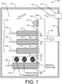
- FIG. 1 shows an example gas meter 100 having an enclosure 102, defining an interior cavity 104.
- a manifold 106 is located within the interior cavity.
- a sensor module 108 and a representative plurality of bypass modules 110, 112, 114 are shown attached to the manifold 106.
- a first gas flow 116 enters the interior cavity 104 of the gas meter 100 through an input port 118.
- a second gas flow 120 leaves the interior cavity 104 passes into the gas sensor 108.
- Other gas flows 122, 124, 126 leave the interior cavity 104, and bypass the gas sensor 108, by passing through bypass modules 110, 112, 114.
- the gas flow 120 may be approximately equal to (e.g., within 10%) the gas flow 122 through one of the bypass modules.
- the gas flows 122, 124, 126 may be approximately equal or may be significantly different.
- the gas flows 120, 122, 124, 126 are unified within the manifold 106, and the outgoing gas flow 128 leaves the gas meter 100 at exhaust port 130.
- the plurality of bypass modules may include bypass modules having at least two different cross-sectional areas and/or lengths over which gas travels within each bypass module.
- the plurality of bypass modules may be configured to allow passage of a bypass gas flow that results in a gas flow through the sensor module to be within an operating range of the sensor module.
- the manifold 106 is configured with sensor module connector(s) and bypass module connector(s). Appropriate sensor module(s) and/or bypass module(s) may be selected and attached to the manifold, according to design requirements, parameters, component availability and component costs.
- the manifold therefore assists in the design and construction of a gas meter for use with larger customers, which uses a sensor module designed for smaller customers.
- the example manifold 106 includes one or more each of sensor module connector(s) and bypass module connector(s).
- sensor module connector 132 allows connection of the sensor module 108. While only one sensor module connector and one sensor module are shown, additional sensor module connector(s) may be included on the manifold 106, with appropriate sensor module(s) installed. If the additional sensor module connectors are not needed, they may be plugged.
- bypass module connectors 134, 136, 138, 140 allow connection of a bypass module or a plug.
- bypass module connector 134 is connected to a plug 142, which prevents gas from leaving the interior cavity 104 and entering the manifold 106.
- bypass module connectors 136, 138, 140 allow connection of bypass modules 110, 112, 114, respectively.
- the bypass modules 110-114 allow gas to bypass the sensor 108.
- the volume of gas bypassing the sensor is accounted for by use of mathematical relationships between the gas volume measured by the sensor and the characteristics of the bypass modules attached to the manifold.
- the sensor module 108 shows a representative design; however, different designs may alternatively be used, which locate processor(s), memory device(s) and/or metrology sensor(s) in alternative locations.
- the sensor module 108 shown includes a processing device 144, memory device 146 and metrology sensor 148. In other configurations, the processor 144 and/or memory 146 may be located in a different part of the gas meter 100.
- a first gas flow 116 enters an interior cavity 104 of the gas meter 100.
- a second flow 120 leaves the interior cavity and passes through the sensor module 108.
- a third flow 150 includes gas flows 122, 124, 126, which pass through bypass modules 110, 112, 114.
- the gas meter 100 determines the gas flow 116 by actual measurement of the gas flow 120 passing through the sensor 108, and by estimation of the gas flows 150 passing through the bypass modules 110, 112, 114. The estimation may be performed by operation of the processing unit 144, using instructions and data stored on the memory device 146.
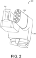
- FIG. 2 shows an example manifold assembly 200 configured for installation within a gas meter (not shown).
- a sensor module 202 is attached to a manifold 206 of the manifold assembly 200.
- the sensor module 202 may be configured for use without a bypass module in a smaller meter (e.g., a meter for a residential or small business customer). However, with a bypass module, the sensor module may be used in a mid-sized gas meter.
- a sensor module 202 and a single bypass module 204 are attached to the manifold 206.
- the sensor module 202 is configured to measure a first portion of the gas flowing through the meter.
- the bypass module 204 is configured to allow a second portion of the gas flowing through the meter to bypass the sensor module.
- measurement of the gas flowing through the meter is based on measurement of a quantity of gas measured by the sensor module 202, and a calculation based on characteristics of the bypass module 204 installed in the manifold 206.
- a look-up table provides a relationship between different measured flowrates of gas (measured by the sensor module 202) and associated percentages of gas that pass through the bypass module 204 at those measured flowrates.
- a ratio of a first flowrate of the first gas flow through a sensor module and a second flowrate of a second gas flow through one or more bypass modules may be variable over a range of gas flowrates and/or pressures at an entry port of a gas meter.
- the gas meter may additionally include a processor to compensate for the variability of the ratio by adjusting a calculation of total gas flow, wherein the adjusting of the calculation is based at least in part on a changing gas flowrate measured by the sensor module.
- a lookup table may be created with different measured flowrates and the percentage of gas that went though the sensor module and/or the percentage of gas that went through the bypass module(s). This lookup table may be created experimentally for each meter design, or for each meter manufactured.
- the bypass module 204 may be constructed to bypass a fixed percentage of the gas flowing through the gas meter at all flowrates or gas pressures appropriate for a particular design-requirement.
- a ratio of a first rate of the first gas flow through a sensor module and a second rate of the second gas flow through one or more bypass modules may be fixed over a range of gas flowrates and/or gas pressures at an entry port of a gas meter.
- the gas meter may additionally include a processor to calculate the total gas flow, such as by multiplying by an appropriate factor.
- FIG. 3 shows an example manifold assembly 300 configured for installation within a gas meter (not shown).
- the gas meter may be configured to measure larger volumes of gas flow than the gas meter of FIG. 2 , and may use the same or different sensor module.
- the sensor module 302 may be configured for use without a bypass module in a smaller meter (e.g., a meter for a residential or small business customer). However, with bypass module(s), the sensor module 302 may be used in a larger gas meter.
- a sensor module 302 and a plurality of bypass modules 304 are attached to the manifold 306.
- the sensor module 302 is configured to measure a first portion of the gas flowing through the meter.
- bypass modules 304 are configured to allow a second portion of the gas flowing through the meter to bypass the sensor module 302. Accordingly, measurement of the gas flowing through the meter is based on measurement of a quantity of gas measured by the sensor module 302, and a calculation based on characteristics of the plurality of bypass modules 304 installed in the manifold 306.
- the sensor module 302 includes an enclosure 310, which may include a processing unit, memory device, and/or a metrology sensor. Accordingly, the sensor module 302 may be configured in the manner of sensor module 108 of FIG. 1 , with processing unit 144, memory device 146, and metrology sensor 148.
- the metrology sensor 148 may be an ultrasonic measuring unit (UMU) or may use other technology as indicated by design requirements.
- a plurality of connectors 308 may each be configured to allow connection of a bypass module 304 or a "plug" or stopper (now shown) to prevent gas flow. Accordingly, the same manifold 306 may be used with differing numbers of bypass modules 304 to create the desired manifold assembly 300.
- all of the plurality of bypass modules 304 may be of the same type, design, size and/or shape, and may be configured to allow the same gas flowrates under like conditions and/or pressures. Accordingly, the same factor could be used to derive the total flowrate from the measured flowrate at all flowrates.
- bypass modules having two or more designs, sizes and/or shapes may be selected and used as the plurality of bypass modules.
- Such diverse bypass modules may be of different type, design, size and/or shape, and may be configured to allow different gas flowrates under like conditions and/or pressures.
- bypass modules having different characteristics may be selected to allow a desired percentage(s) of the gas flowing through the gas meter to bypass the sensor module over an anticipated range of gas flows through the meter.
- a bypass module(s) could be replaced by an additional sensor module(s). This would allow a gas meter to measure a greater percentage of the gas flow, and would allow the data from the sensor modules to be compared and contrasted. The data would also allow for the generation of diagnostics, for the performance of self-tests, and for greater flexibility in the design and operation of gas meters configured with two or more sensor modules.
- a factor is derived (e.g., and added to a lookup table) for use in deriving the total flowrate through the meter.
- the factor is adjusted as the gas meter ages.
- FIG. 4 shows an example gas meter 400.
- a gas flow enters the meter, and within the enclosure of the meter the flow is bifurcated, with separate flows passing through either a sensor module or a bypass module that allows gas to "bypass" the sensor module.
- the gas flows may be reunified in a manifold before exiting the meter.
- the example meter 400 includes a measuring, sensor and/or metrology module and a bypass module.
- the bypass module allows gas to "bypass" the measuring module, thereby allowing utilization of a less expensive sensor module. Gas that bypasses the sensor/metrology module is accounted for by the meter 400.
- the sensor module and the bypass module are connected to a manifold, which is connected to an outlet of the meter.
- the bypass module may have a conic shape and a slot, wherein an opening angle of the bypass module is calculated to create a bypass ratio which depends on, or is a function of, the measured flowrate. In an example, the bypass ratio could than have the response that is similar to FIG. 19 .
- the bypass ratio may be the ratio of gas passing through the sensor module divided by the gas passing through the bypass module.
- the bypass ratio is the ratio of gas passing through the sensor module divided by the total gas passing through the meter.
- the numerator and denominator of the ratio could be reversed. Accordingly, the bypass ratio is a ratio, equation and/or relationship that relates two or more of measured, unmeasured and/or total gas, and allows calculation of the overall gas flowrate and/or volume using the measured gas flowrate and/or volume.
- the design of the example meter 400 allows the minimization or reduction of measurement uncertainty at low flowrates (where pressure drop is not problematic) and reduces or minimizes pressure drop at higher flowrates (where measurement uncertainty is not problematic).
- a threaded connector 402 allows a gas flow 404 to enter an enclosure 406 of the meter 400.
- a first flow 408 of gas from within the enclosure 406 passes into and through a sensor module or metrology module 410.
- a second flow 412 gas from within the enclosure 406 passes into and through a bypass module 414.
- the first gas flow 408 and the second gas flow 412 are unified within the manifold 416, and a unified gas flow 418 exits the meter 400 at threaded connector 420.
- gas meter 400 shown there is only one bypass module 414 attached to the manifold 416.
- two or more bypass modules 414 could be attached to the manifold.
- the bypass modules are the same (e.g., same size, shape, length, etc.).
- the bypass modules may be configured according to two or more designs, each design having one or more differences from one or more other designs.
- the bypass modules may be configured to have a size, shape and/or configuration that is the same, or substantially similar, to the gas-flow passages of the sensor module 410.
- bypass module In example use of one such bypass module, half the gas flow from the meter enclosure into the manifold would pass through the sensor module and half of the gas flow would pass through the bypass module. In example use of two such bypass modules, one-third of the gas flow from the meter enclosure into the manifold would pass through the sensor module and two-thirds of the gas flow would pass through the two bypass modules. In such examples, the percentage of the volume of the total gas flow passing through the meter could be derived by multiplying the measured gas flow by an appropriate factor.
- FIG. 5 shows an example gas meter 500, showing a manifold assembly having a different manifold than was shown in FIG. 4 .
- a threaded connector 502 allows a gas flow 504 to enter an enclosure 506 of the meter 500.
- a first flow 508 of gas from within the enclosure 506 passes into and through a sensor module or metrology module 510.
- a second flow 512 gas from within the enclosure 506 passes into and through a bypass module 514.
- the first gas flow 508 and the second gas flow 512 are unified within the manifold 516, and a unified gas flow 518 exits the meter 500 at threaded connector 520.
- FIG. 6 is an additional perspective view of the manifold assembly 600, rotated approximately 180-degrees and removed from the gas meter 500 of FIG. 5 .
- the manifold 516 is configured for attachment of one bypass module 514 and the sensor module 510 (substantially obscured in the view of FIG. 1 ) to show the reverse side of the manifold.
- FIG. 7 shows a further example of a manifold assembly 700, a sensor module and bypass module.
- a sensor module 702 and a bypass module 704 are connected to a manifold 706.
- FIG. 8 shows an example bypass module 800.
- a tubular body 802 may be made of aluminum or aluminum alloy.
- An entry fixture 804 is configured to smooth the incoming gas flow and reduce turbulence.
- a footing 806 is configured to attach to a manifold (manifold not shown in this view).
- FIG. 9 shows an example bypass module 900.
- a tubular body 902, entry fixture 904 and a footing 906 are made of a single material, such as plastic.
- the entry fixture 904 is configured to smooth the incoming gas flow and reduce turbulence.
- the footing 906 is configured to attach to a manifold (not shown).
- FIG. 10 shows an additional example of a manifold assembly 1000.
- a sensor module and a plurality of bypass modules result in less measured gas flow and more bypassed gas flow.
- the sensor module 1002 is associated with an enclosure 1004, which may include a processing unit, memory device, and/or a metrology sensor.
- a plurality of bypass modules 1006 allow gas to enter the manifold 1008 without passing through the sensor module 1002.
- the manifold 1008 has an exhaust port 1010 which exhausts gas that has passed through any of the sensor module 1002 or bypass modules 1006.
- FIG. 10 is shown with a manifold 1008 having a single sensor module 1002 and six bypass modules 1006.
- one or more of the bypass modules 1006 could be replaced by an additional sensor module 1002. This would result in a greater percentage of the overall gas flow going through a sensor module and a small percentage of the overall gas flow going through a bypass module. Additionally, this would provide two sources of gas flowrate data. These data flows could be compared over time, and diagnostics could be generated. In an example, degraded performance of one of the sensor modules may be assumed, if the percentage of the overall gas flow measured by the two sensor modules changes. Accordingly, while FIG. 10 shows one sensor module and six bypass modules, any number of sensor modules and bypass modules could be used. In a further example, where two or more sensor modules are used, one or more of the sensor modules may be turned off during period(s) of time, such as in response to higher or lower gas flows.
- FIG. 11 shows an example gas meter 1100.
- An entry port 1102 receives gas, such as from a utility company.
- An exit port 1104 exhausts gas after measurement, such as to a utility customer.
- the enclosure 1106 is shown as partially transparent to provide a view of the interior of the meter.
- the manifold assembly 1000 of FIG. 10 is shown.
- the manifold assembly 1000, with a sensor module and a plurality of bypass modules measures gas before it exits the meter at port 1104.
- a deflector or baffle 1108 regulates the flow of gas from the entry port 1102 tends to reduce turbulence and create a more laminar flow of gas as it moves toward the manifold assembly 1000.
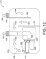
- FIG. 12 shows an example gas meter 1200.
- Gas 1202 e.g., from a utility company
- the gas flow 1206 is directed in part by a baffle 1208, which reduces turbulence.
- the gas flow 1210 travels between baffles 1208, 12012.
- the gas flow 1214 proceeds toward the opposite end of the gas meter, where gas flow 1216 is redirected by the inside surface of the enclosure 1218.
- Gas flow 1220 approaches the sensor module 1222, having an enclosure 1224 for a processor, memory, and a sensor device.
- Gas also enters a bypass module 1226. Within the module 1228, the gas flows from the sensor module 1222 and bypass module 1226 are unified as gas flow 1230. Gas flow 1232 then exits through exhaust port 1234.
- the gas meter 1200 shows that one or more baffles 1208, 1212 can reduce turbulence and increase laminar gas flow characteristics. Also, by putting the input of the sensor module 1222 and the bypass module 1226 near a wall of the enclosure 1218, gas turbulence is also reduced. By reducing turbulence, a more accurate gas flowrate measurement is made.
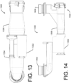
- FIG. 13 shows a top view of an example manifold assembly 1300.
- the assembly includes a gas sensor module 1302, bypass module 1304, and manifold 1306.
- the sensor module 1302 and bypass module 1304 are attached to the manifold 1306.
- FIG. 14 shows a side-view of the example manifold assembly 1300.
- An input port 1402, an exhaust port 1404, and the manifold 1306 are shown.
- the valve assembly 1400 allows the exhaust port 1404 to be closed.
- FIG. 15 is a top view of an example manifold assembly 1300.
- a gas entry connector or port 1402 and the shut-off valve 1400 are shown.
- the sensor module 1302 and bypass module 1304 are also shown.
- FIG. 16 is an end view of the manifold assembly 1300. The exhaust port 1404 and valve assembly 1400 are shown.
- FIG. 17 is an end view of the manifold assembly 1300, bypass module, and sensor module.
- the gas inlet port 1402 is shown.
- the sensor module 1302 and bypass module 1304 are attached to the manifold.
- Module 1700 encloses electronics, which may include one or more of a processing unit, memory device, and/or metrology sensor.
- FIG. 18 is a perspective view of the manifold 1306, bypass module, sensor module and valve 1400.
- the entry port 1402 and exhaust port 1404 are shown.
- the sensor module 1302 and bypass module 1304 are
- FIG. 19 shows a compound manifold assembly 1900.
- Sensor modules 1902, 1904 are seen in the foreground, and are associated with respective bypass modules 1906, 1908.
- Each sensor module has an electronics module 1910, which may include one or more of a processor unit, a memory device, and/or a metrology sensor.
- Each sensor module and bypass module pair exhausts gas into a secondary manifold 1912.
- Each secondary manifold exhausts gas into a collector pipe 1914, which transfers gas to a primary manifold 1916. Gas is finally exhausted from an outlet 1918.
- the compound manifold assembly 1900 may be contained within an enclosure (not shown for clarity) of a gas meter.
- any of the gas manifold assemblies of the previous figures could be attached to the primary manifold 1916.
- a gas meter having a larger gas flowrate-measuring capacity could be configured with a primary manifold 1916 attached to (fed by) any combination (e.g., mix or match) of sensor module(s)/bypass module(s) of the earlier figures.
- the assembly is configured so that a distance from an opening of each sensor module 1902 and each bypass module 1906 is the same distance. Such a configuration may result in increased accuracy of gas flowrate measurement.
- a position of the on/off valve of one or more of the manifold assemblies used to form the compound manifold assembly may be changed. Such valve settings may further customize the compound manifold assembly.
- FIG. 20 shows an example chart 2000 illustrating a bypass ratio for different total gas flowrates.
- a fixed percentage of gas flows through the sensor module.
- 50% of the gas flow is though the sensor module, then total gas flow is twice measured gas flow. This calculation is easily made if a different fixed percentage of the gas flows through the sensor module.
- the percentage of gas flowing through the sensor module is fixed over time for any given gas flowrate. However, for different gas flowrates, the percentage of gas flowing through the sensor module varies. FIG. 19 addresses this issue.
- the graph and/or associated lookup table can be created. The experimentation may be made for any particular meter design or for any particular meter (i.e., a custom lookup table for each meter manufactured).
- a gas meter may determine a sequence of flowrates, as a customer uses gas. Using a lookup table, a gas meter may determine an appropriate factor for each measured flowrate, to determine a total gas flowrate. Thus, gas measurement includes measuring a flowrate and obtaining a factor associated with the flowrate to yield total gas flowrate.
- the percentage of the gas passing through bypass module(s) is equal to the percentage of gas measured at 2002.
- the percentage of gas passing through bypass module(s) is slightly higher at 2004 and lower at 2006 than the percentage of gas passing through the sensor module.
- FIG. 21 shows example methods 2100 and operation of a gas meter.
- the methods and operation may be performed and/or directed by any desired processor, memory, integrated circuit, logic devices, programming, etc.
- a controller may include one or more of the processor, memory and/or other devices.
- the example methods of FIG. 21 may be implemented at least in part using the structures and techniques illustrated by FIGS. 1-20 . However, the methods of FIG. 21 contain general applicability, and are not limited by other drawing figures and/or prior discussion.
- the functional blocks of FIG. 21 may be implemented by software and/or hardware structures or devices that are configured to operate a gas meter.
- the methods of operation may be performed by one or more application specific integrated circuits (ASIC) or may be performed by a general-purpose processor utilizing software defined in computer readable media.
- the memory 146 may comprise computer-readable media and may take the form of volatile memory, such as random-access memory (RAM) and/or non-volatile memory, such as read only memory (ROM) or flash RAM.
- RAM random-access memory
- ROM read only memory
- Computer-readable media devices include volatile and non-volatile, removable and non-removable media implemented in any method or technology for storage of information such as computer-readable instructions, data structures, program modules, or other data for execution by one or more processors of a computing device.
- Examples of computer-readable media include, but are not limited to, phase change memory (PRAM), static random-access memory (SRAM), dynamic random-access memory (DRAM), other types of random access memory (RAM), read-only memory (ROM), electrically erasable programmable read-only memory (EEPROM), flash memory or other memory technology, compact disk read-only memory (CD-ROM), digital versatile disks (DVD) or other optical storage, magnetic cassettes, magnetic tape, magnetic disk storage or other magnetic storage devices, or any other non-transitory medium that can be used to store information for access by a computing device.
- PRAM phase change memory
- SRAM static random-access memory
- DRAM dynamic random-access memory
- RAM random access memory
- ROM read-only memory
- EEPROM electrically erasable programmable read-only memory
- flash memory or other memory technology
- CD-ROM compact disk read-only memory
- DVD digital versatile disks
- computer-readable media does not include transitory media, such as modulated data signals and carrier waves, and/or signals.
- FIG. 21 shows an example method 2100 by which a volume of gas is measured in a gas meter having a manifold with attached sensor module(s) and bypass module(s).
- a gas flow is received by the gas meter.
- a portion of the gas flow is passes through a gas sensor module, where it is measured.
- Another portion of the gas flow passes through one or more bypass modules, thereby bypassing the gas sensor module.
- a manifold provides connectors to allow attachment of the gas sensor module(s) and/or the bypass module(s).
- a relationship between two or more of: a volume of gas flowing into the meter; a volume of gas flowing through the gas sensor module(s); and a volume of gas flowing through the bypass module(s) is known over a range of gas flowrates. Accordingly, by using the relationship and measured values from the gas sensor module, a flowrate of gas flowing through the meter, and a volume of gas that passed through the meter over time, can be determined.
- a first gas flow having a first gas flowrate is received into an interior of a gas meter.
- a second gas flow having a measured second gas flowrate, is measured by operation of a sensor module.
- the measured second gas flowrate is a portion of the first (i.e., total) gas flow rate.
- the measuring may be performed by one or more sensor modules.
- the sensor modules may be connected to a manifold within a gas meter.
- a third gas flow bypasses the sensor module(s) and is carried by a bypass module.
- the third gas flow bypasses the sensor module(s) by passing through a plurality of bypass modules.
- gas flow is blocked from flowing into the manifold by one or more stoppers or plugs. Accordingly, the gas is routed into the manifold through the sensor module(s) or the bypass module(s).
- data (such as a multiplicative factor) is obtained to compensate for variability of a ratio of the measured second gas flowrate to the third gas flow rate. That variability is seen in FIG. 20 .
- the variability (and compensation for the variability) may be based at least in part on the measured second gas flowrate.
- the variability may be based at least in part on a number of bypass modules used.
- the gas flowrate through the meter is measured (e.g., a flowrate measured at the sensor module) and data (e.g., a multiplicative factor) based on the measured flowrate (e.g., data from FIG.
- the data or multiplicative factor is approximately 2 for most measured gas flows. That is, approximately half of the overall gas flow is measured, and the full gas flow is (approximately) the measured gas flow times two. However, for some gas flowrates, it is less than 2, and for some gas flowrates it is more than 2. Accordingly, there is variability in the multiplicative factor, which may be repeatedly updated from a lookup table, as the sensor module makes measurements. If an additional bypass module was used, the factor might increase.
- a plurality of values may be used for the ratio of the measured second gas flowrate to the third gas flow-rate for each of a respective plurality of measured second gas flowrates.
- a lookup table is accessed, which may be customized for the gas meter design, or for the gas meter individually.
- any one of the ratios can be used as a factor to determine a total flowrate from a measured flowrate. Accordingly, statement of one relationship implies and includes the others.
- the first gas flowrate is determined. The determination may be made based on input including the measured second gas flowrate and a compensation factor for the variability of a measured gas flowrate and a bypassed gas flowrate.
- output from two sensor modules may be compared to determine if the output is within a threshold difference and/or whether the gas meter should be replaced. If the output of the two sensor modules have a ratio or other relationship that has changed, then that change may indicate a failure of the gas meter.
Landscapes
- Physics & Mathematics (AREA)
- Fluid Mechanics (AREA)
- General Physics & Mathematics (AREA)
- Measuring Volume Flow (AREA)
- Exhaust Gas After Treatment (AREA)
Claims (12)
- Gaszähler (100), der Folgendes umfasst:ein Gehäuse (102), das einen Einlassanschluss (118), einen Auslassanschluss (130) und einen Innenhohlraum (104) definiert;einen innerhalb des Innenhohlraums des Gehäuses angeordneten Verteiler (106), der einen ersten Verbinder, einen zweiten Verbinder und einen dritten Verbinder umfasst, wobei der Verteiler mit dem Auslassanschluss verbunden ist, um Abgas durch den Auslassanschluss abzugeben;ein Ventil, das mit dem Verteiler verbunden ist, um eine Gasströmung von dem Verteiler zu dem Auslassanschluss zu regeln;ein Sensormodul (108), das mit dem ersten Verbinder des Verteilers verbunden und dazu ausgelegt ist, eine erste Gasströmungsrate von dem Innenhohlraum des Gehäuses, durch das Sensormodul, durch den Verteiler und aus dem Auslassanschluss hinaus zu messen;ein Umlenkungsmodul (110, 112, 114), das mit dem zweiten Verbinder des Verteilers verbunden ist, um eine zweite Gasströmung mit einer zweiten Gasströmungsrate von dem Innenhohlraum des Gehäuses, durch das Umlenkungsmodul, durch den Verteiler und aus dem Auslassanschluss hinaus zu leiten; undeinen Stopfen (142), der mit dem dritten Verbinder (134) verbunden ist, um ein Eintreten einer Gasströmung in den Verteiler durch den dritten Verbinder zu blockieren; und einen Prozessor (144) zum Berechnen einer Gesamtgasströmungsrate durch den Gaszähler unter Verwendung von Eingaben, die Folgendes umfassen:eine gemessene Gasströmungsrate durch das Sensormodul; undeinen Anpassungsfaktor, wobei der Anpassungsfaktor auf der gemessenen Gasströmungsrate basiert; wobei der Anpassungsfaktor erhalten wird durch:
Verwenden einer Mehrzahl von Werten für den Faktor für jede einer jeweiligen Mehrzahl von gemessenen zweiten Gasströmungsraten. - Gaszähler nach Anspruch 1, der zusätzlich Folgendes umfasst:
ein oder mehrere Prallbleche (1108, 1208) innerhalb des Innenhohlraums (104) des Gaszählers, um die Gasströmung durch den Innenhohlraum des Gaszählers umzuleiten. - Gaszähler nach Anspruch 1, wobei das Umlenkungsmodul (110-114) einen Strömungsdurchgang aufweist, der ungefähr gleich dem Strömungsdurchgang des Sensormoduls ist.
- Gaszähler nach Anspruch 1, der zusätzlich Folgendes umfasst:ein zweites Sensormodul; undeinen Prozessor (144) und eine Speichervorrichtung (146);wobei der Prozessor Daten von dem Sensormodul und dem zweiten Sensormodul vergleicht, um zu bestimmen, ob die Daten innerhalb einer Schwellendifferenz liegen.
- Gaszähler nach Anspruch 1, wobei die Mehrzahl von Werten für den Faktor zumindest teilweise auf einer Nachschlagetabelle basieren, und wobei die Nachschlagetabelle eine Beziehung zwischen unterschiedlichen gemessenen Gasströmungsraten und zugehörigen Gasprozentsätzen, die bei diesen gemessenen Strömungsraten durch das Umlenkungsmodul strömen, bereitstellt.
- Verfahren (2100) zum Messen einer Gasströmung, das Folgendes umfasst:Empfangen (2102) einer Gesamtgasströmung mit einer Gesamtgasströmungsrate in ein Inneres eines Gaszählers;Messen (2104) einer ersten Gasströmung, um dadurch eine gemessene erste Gasströmungsrate zu erhalten, wobei das Messen durch ein Sensormodul durchgeführt wird und die erste Gasströmung ein Teil der Gesamtgasströmung ist;Umlenken (2108) einer zweiten Gasströmung mit einer zweiten Gasströmungsrate durch ein Umlenkungsmodul, wobei die zweite Gasströmung ein Teil der Gesamtgasströmung ist und von der ersten Gasströmung getrennt ist;Erhalten (2114) eines Faktors zumindest teilweise basierend auf der gemessenen ersten Gasströmungsrate;
undBestimmen (2122) der Gesamtgasströmungrate basierend auf Eingaben, die Folgendes umfassen:die gemessene erste Gasströmungsrate; undden Faktor; wobei das Erhalten (2114) des Faktors Folgendes umfasst:
Verwenden einer Mehrzahl von Werten für den Faktor für jede einer jeweiligen Mehrzahl von gemessenen zweiten Gasströmungsraten. - Verfahren nach Anspruch 6, wobei das Umlenkungsmodul eines einer Mehrzahl von Umlenkungsmodulen ist, und wobei das Umlenken der dritten Gasströmung Folgendes umfasst:
Umlenken der dritten Gasströmung durch die Mehrzahl von Umlenkungsmodulen. - Verfahren nach Anspruch 6, wobei das Sensormodul eines von zwei Sensormodulen ist, und wobei das Verfahren zusätzlich Folgendes umfasst:Vergleichen (2124) einer Ausgabe von den zwei Sensormodulen; undBestimmen, ob der Gaszähler ausgetauscht werden sollte, basierend auf dem Vergleich.
- Verfahren nach Anspruch 6, wobei Erhalten des Faktors zumindest teilweise auf Zugreifen auf eine Nachschlagetabelle basiert, und wobei Messen einer Gasströmung zusätzlich Folgendes umfasst:
Bereitstellen einer benutzerdefinierten Nachschlagetabelle für den Gaszähler basierend auf einer Prüfung des Gaszählers. - Verfahren nach Anspruch 6, wobei Abgas des Sensormoduls und des Umlenkungsmoduls in einen Verteiler fließt, und wobei das Verfahren zusätzlich Folgendes umfasst:
Blockieren einer Gasströmung in den Verteiler an mindestens einer Stelle unter Verwendung mindestens eines Stopfens in mindestens einem jeweiligen Umlenkungsmodulverbinder. - Verfahren nach Anspruch 6, wobei:Messen der ersten Gasströmung Leiten von Gas von dem Inneren des Gaszählers durch das Sensormodul und in einen Verteiler umfasst; undUmlenken der zweiten Gasströmung Leiten von Gas von dem Inneren des Gaszählers durch das Umlenkungsmodul und mindestens ein anderes Umlenkungsmodul und in den Verteiler umfasst.
- Verfahren nach Anspruch 9, wobei die Nachschlagetabelle eine Beziehung zwischen unterschiedlichen gemessenen Gasströmungsraten und zugehörigen Gasprozentsätzen, die bei diesen gemessenen Strömungsraten durch das Umlenkungsmodul strömen, bereitstellt.
Applications Claiming Priority (2)
| Application Number | Priority Date | Filing Date | Title |
|---|---|---|---|
| US16/725,591 US11333540B2 (en) | 2019-12-23 | 2019-12-23 | Sensor bypass for gas meters |
| PCT/US2020/066934 WO2021133968A1 (en) | 2019-12-23 | 2020-12-23 | Sensor bypass for gas meters |
Publications (2)
| Publication Number | Publication Date |
|---|---|
| EP4022263A1 EP4022263A1 (de) | 2022-07-06 |
| EP4022263B1 true EP4022263B1 (de) | 2025-01-22 |
Family
ID=74181402
Family Applications (1)
| Application Number | Title | Priority Date | Filing Date |
|---|---|---|---|
| EP20839546.7A Active EP4022263B1 (de) | 2019-12-23 | 2020-12-23 | Sensorbypass für gaszähler |
Country Status (5)
| Country | Link |
|---|---|
| US (1) | US11333540B2 (de) |
| EP (1) | EP4022263B1 (de) |
| CA (1) | CA3156279C (de) |
| ES (1) | ES3014603T3 (de) |
| WO (1) | WO2021133968A1 (de) |
Families Citing this family (10)
| Publication number | Priority date | Publication date | Assignee | Title |
|---|---|---|---|---|
| US11982373B2 (en) | 2020-12-18 | 2024-05-14 | Itron, Inc. | Gas regulator diaphragm-position and pressure-relief detection |
| US11971285B2 (en) | 2020-12-18 | 2024-04-30 | Itron, Inc. | Detection of low gas pressure without pressure sensors |
| US11971291B2 (en) | 2020-12-18 | 2024-04-30 | Itron, Inc. | Gas regulator pressure-relief monitor |
| US11601506B2 (en) | 2020-12-18 | 2023-03-07 | Itron, Inc. | Disaggregation of gas load to determine gas appliance performance |
| US11733075B2 (en) | 2020-12-18 | 2023-08-22 | Itron, Inc. | Disaggregation of gas load to determine meter or service under-sizing |
| US11594117B2 (en) | 2020-12-18 | 2023-02-28 | Itron, Inc. | Network edge detection and notification of gas pressure situation |
| US12196593B2 (en) | 2020-12-18 | 2025-01-14 | Itron, Inc. | Network edge detection and notification of gas pressure situation |
| US11726073B1 (en) | 2022-02-02 | 2023-08-15 | Honeywell International Inc. | Commercial and residential meter bypass system |
| US12455180B2 (en) | 2022-12-02 | 2025-10-28 | Honeywell International Inc. | System and method for switched measuring of flow tubes of a flow meter |
| IT202300011481A1 (it) * | 2023-06-06 | 2024-12-06 | Pietro Fiorentini Spa | Misuratore del gas perfezionato. |
Family Cites Families (6)
| Publication number | Priority date | Publication date | Assignee | Title |
|---|---|---|---|---|
| US5509305A (en) * | 1992-02-12 | 1996-04-23 | Daniel Industries, Inc. | Closely coupled, dual turbine volumetric flow meter |
| US5868155A (en) * | 1996-03-13 | 1999-02-09 | Hutton; Peter B. | Valve manifold system |
| JPH11287688A (ja) * | 1998-04-01 | 1999-10-19 | Matsushita Electric Ind Co Ltd | 流量計測装置 |
| JP6087695B2 (ja) * | 2013-03-28 | 2017-03-01 | 大阪瓦斯株式会社 | 超音波式ガスメータ |
| JP6263738B2 (ja) * | 2014-02-07 | 2018-01-24 | パナソニックIpマネジメント株式会社 | ガス流量計 |
| JP2015148530A (ja) * | 2014-02-07 | 2015-08-20 | パナソニックIpマネジメント株式会社 | ガス流量計 |
-
2019
- 2019-12-23 US US16/725,591 patent/US11333540B2/en active Active
-
2020
- 2020-12-23 ES ES20839546T patent/ES3014603T3/es active Active
- 2020-12-23 WO PCT/US2020/066934 patent/WO2021133968A1/en not_active Ceased
- 2020-12-23 CA CA3156279A patent/CA3156279C/en active Active
- 2020-12-23 EP EP20839546.7A patent/EP4022263B1/de active Active
Also Published As
| Publication number | Publication date |
|---|---|
| US11333540B2 (en) | 2022-05-17 |
| ES3014603T3 (en) | 2025-04-23 |
| WO2021133968A1 (en) | 2021-07-01 |
| US20210190568A1 (en) | 2021-06-24 |
| CA3156279A1 (en) | 2021-07-01 |
| EP4022263A1 (de) | 2022-07-06 |
| CA3156279C (en) | 2024-11-19 |
Similar Documents
| Publication | Publication Date | Title |
|---|---|---|
| US11333540B2 (en) | Sensor bypass for gas meters | |
| US5925829A (en) | Method and apparatus for determining a rate of flow of gas by a rate of change of pressure | |
| US7412336B2 (en) | Attitude insensitive flow device system and method | |
| US6236948B1 (en) | Process and device for determining a measured value of a target measured variable of a multiphase flow | |
| US7287434B2 (en) | System and method for measuring flow | |
| KR102901028B1 (ko) | 질량 유량, 밀도, 온도 및/또는 유속을 측정하기 위한 측정 시스템 | |
| US11959788B2 (en) | Wide range flow measuring device having two Coriolis meters arranged in series and a bypass line to bypass the second Coriolis meter | |
| CA2867010C (en) | Indirect mass flow sensor | |
| US10539446B2 (en) | Method for adjusting flow measuring device | |
| JP5454603B2 (ja) | 流量測定装置 | |
| JP2015224872A (ja) | 超音波流量計 | |
| JP5465703B2 (ja) | 流量センサ | |
| JPS6329209Y2 (de) | ||
| JP3818547B2 (ja) | 質量流量制御装置 | |
| JP3252187B2 (ja) | 流量計 | |
| JP2735678B2 (ja) | 流速センサ型流量計 | |
| JP2000241218A (ja) | 流量計 | |
| JPS5827020A (ja) | 広範囲型流量測定装置 | |
| RU2366906C2 (ru) | Устройство для поверки расходомеров | |
| KR102155528B1 (ko) | 유량튜브 및 이를 포함하는 가스미터 | |
| PL2039B1 (pl) | Urzadzenie do mierzenia przeplywajacych mas gazowych. | |
| CN112577557A (zh) | 超声波流量计和流体管路 | |
| JP2006058201A (ja) | 熱伝導型ガス分析器 | |
| CZ4176U1 (cs) | Zařízení pro měření spotřeby tlakového plynu | |
| JPS59137820A (ja) | 流量計式弁開度指示計 |
Legal Events
| Date | Code | Title | Description |
|---|---|---|---|
| STAA | Information on the status of an ep patent application or granted ep patent |
Free format text: STATUS: UNKNOWN |
|
| STAA | Information on the status of an ep patent application or granted ep patent |
Free format text: STATUS: THE INTERNATIONAL PUBLICATION HAS BEEN MADE |
|
| PUAI | Public reference made under article 153(3) epc to a published international application that has entered the european phase |
Free format text: ORIGINAL CODE: 0009012 |
|
| STAA | Information on the status of an ep patent application or granted ep patent |
Free format text: STATUS: REQUEST FOR EXAMINATION WAS MADE |
|
| 17P | Request for examination filed |
Effective date: 20220330 |
|
| AK | Designated contracting states |
Kind code of ref document: A1 Designated state(s): AL AT BE BG CH CY CZ DE DK EE ES FI FR GB GR HR HU IE IS IT LI LT LU LV MC MK MT NL NO PL PT RO RS SE SI SK SM TR |
|
| DAV | Request for validation of the european patent (deleted) | ||
| DAX | Request for extension of the european patent (deleted) | ||
| P01 | Opt-out of the competence of the unified patent court (upc) registered |
Effective date: 20230519 |
|
| REG | Reference to a national code |
Ref country code: DE Ref legal event code: R079 Free format text: PREVIOUS MAIN CLASS: G01F0005000000 Ipc: G01F0015180000 Ref country code: DE Ref legal event code: R079 Ref document number: 602020045270 Country of ref document: DE Free format text: PREVIOUS MAIN CLASS: G01F0005000000 Ipc: G01F0015180000 |
|
| GRAP | Despatch of communication of intention to grant a patent |
Free format text: ORIGINAL CODE: EPIDOSNIGR1 |
|
| STAA | Information on the status of an ep patent application or granted ep patent |
Free format text: STATUS: GRANT OF PATENT IS INTENDED |
|
| RIC1 | Information provided on ipc code assigned before grant |
Ipc: G01F 1/66 20220101ALI20240124BHEP Ipc: G01F 5/00 20060101ALI20240124BHEP Ipc: G01F 15/18 20060101AFI20240124BHEP |
|
| INTG | Intention to grant announced |
Effective date: 20240209 |
|
| GRAJ | Information related to disapproval of communication of intention to grant by the applicant or resumption of examination proceedings by the epo deleted |
Free format text: ORIGINAL CODE: EPIDOSDIGR1 |
|
| STAA | Information on the status of an ep patent application or granted ep patent |
Free format text: STATUS: REQUEST FOR EXAMINATION WAS MADE |
|
| INTC | Intention to grant announced (deleted) | ||
| GRAP | Despatch of communication of intention to grant a patent |
Free format text: ORIGINAL CODE: EPIDOSNIGR1 |
|
| STAA | Information on the status of an ep patent application or granted ep patent |
Free format text: STATUS: GRANT OF PATENT IS INTENDED |
|
| INTG | Intention to grant announced |
Effective date: 20240812 |
|
| GRAS | Grant fee paid |
Free format text: ORIGINAL CODE: EPIDOSNIGR3 |
|
| GRAA | (expected) grant |
Free format text: ORIGINAL CODE: 0009210 |
|
| STAA | Information on the status of an ep patent application or granted ep patent |
Free format text: STATUS: THE PATENT HAS BEEN GRANTED |
|
| AK | Designated contracting states |
Kind code of ref document: B1 Designated state(s): AL AT BE BG CH CY CZ DE DK EE ES FI FR GB GR HR HU IE IS IT LI LT LU LV MC MK MT NL NO PL PT RO RS SE SI SK SM TR |
|
| REG | Reference to a national code |
Ref country code: GB Ref legal event code: FG4D |
|
| REG | Reference to a national code |
Ref country code: CH Ref legal event code: EP |
|
| REG | Reference to a national code |
Ref country code: IE Ref legal event code: FG4D |
|
| REG | Reference to a national code |
Ref country code: DE Ref legal event code: R096 Ref document number: 602020045270 Country of ref document: DE |
|
| REG | Reference to a national code |
Ref country code: ES Ref legal event code: FG2A Ref document number: 3014603 Country of ref document: ES Kind code of ref document: T3 Effective date: 20250423 |
|
| REG | Reference to a national code |
Ref country code: NL Ref legal event code: MP Effective date: 20250122 |
|
| PG25 | Lapsed in a contracting state [announced via postgrant information from national office to epo] |
Ref country code: NL Free format text: LAPSE BECAUSE OF FAILURE TO SUBMIT A TRANSLATION OF THE DESCRIPTION OR TO PAY THE FEE WITHIN THE PRESCRIBED TIME-LIMIT Effective date: 20250122 |
|
| PG25 | Lapsed in a contracting state [announced via postgrant information from national office to epo] |
Ref country code: RS Free format text: LAPSE BECAUSE OF FAILURE TO SUBMIT A TRANSLATION OF THE DESCRIPTION OR TO PAY THE FEE WITHIN THE PRESCRIBED TIME-LIMIT Effective date: 20250422 |
|
| PG25 | Lapsed in a contracting state [announced via postgrant information from national office to epo] |
Ref country code: FI Free format text: LAPSE BECAUSE OF FAILURE TO SUBMIT A TRANSLATION OF THE DESCRIPTION OR TO PAY THE FEE WITHIN THE PRESCRIBED TIME-LIMIT Effective date: 20250122 |
|
| PG25 | Lapsed in a contracting state [announced via postgrant information from national office to epo] |
Ref country code: PL Free format text: LAPSE BECAUSE OF FAILURE TO SUBMIT A TRANSLATION OF THE DESCRIPTION OR TO PAY THE FEE WITHIN THE PRESCRIBED TIME-LIMIT Effective date: 20250122 |
|
| REG | Reference to a national code |
Ref country code: LT Ref legal event code: MG9D |
|
| PG25 | Lapsed in a contracting state [announced via postgrant information from national office to epo] |
Ref country code: NO Free format text: LAPSE BECAUSE OF FAILURE TO SUBMIT A TRANSLATION OF THE DESCRIPTION OR TO PAY THE FEE WITHIN THE PRESCRIBED TIME-LIMIT Effective date: 20250422 Ref country code: IS Free format text: LAPSE BECAUSE OF FAILURE TO SUBMIT A TRANSLATION OF THE DESCRIPTION OR TO PAY THE FEE WITHIN THE PRESCRIBED TIME-LIMIT Effective date: 20250522 |
|
| REG | Reference to a national code |
Ref country code: AT Ref legal event code: MK05 Ref document number: 1761776 Country of ref document: AT Kind code of ref document: T Effective date: 20250122 |
|
| PG25 | Lapsed in a contracting state [announced via postgrant information from national office to epo] |
Ref country code: HR Free format text: LAPSE BECAUSE OF FAILURE TO SUBMIT A TRANSLATION OF THE DESCRIPTION OR TO PAY THE FEE WITHIN THE PRESCRIBED TIME-LIMIT Effective date: 20250122 |
|
| PG25 | Lapsed in a contracting state [announced via postgrant information from national office to epo] |
Ref country code: PT Free format text: LAPSE BECAUSE OF FAILURE TO SUBMIT A TRANSLATION OF THE DESCRIPTION OR TO PAY THE FEE WITHIN THE PRESCRIBED TIME-LIMIT Effective date: 20250522 Ref country code: LV Free format text: LAPSE BECAUSE OF FAILURE TO SUBMIT A TRANSLATION OF THE DESCRIPTION OR TO PAY THE FEE WITHIN THE PRESCRIBED TIME-LIMIT Effective date: 20250122 |
|
| PG25 | Lapsed in a contracting state [announced via postgrant information from national office to epo] |
Ref country code: BG Free format text: LAPSE BECAUSE OF FAILURE TO SUBMIT A TRANSLATION OF THE DESCRIPTION OR TO PAY THE FEE WITHIN THE PRESCRIBED TIME-LIMIT Effective date: 20250122 Ref country code: GR Free format text: LAPSE BECAUSE OF FAILURE TO SUBMIT A TRANSLATION OF THE DESCRIPTION OR TO PAY THE FEE WITHIN THE PRESCRIBED TIME-LIMIT Effective date: 20250423 |
|
| PG25 | Lapsed in a contracting state [announced via postgrant information from national office to epo] |
Ref country code: AT Free format text: LAPSE BECAUSE OF FAILURE TO SUBMIT A TRANSLATION OF THE DESCRIPTION OR TO PAY THE FEE WITHIN THE PRESCRIBED TIME-LIMIT Effective date: 20250122 |
|
| PG25 | Lapsed in a contracting state [announced via postgrant information from national office to epo] |
Ref country code: SE Free format text: LAPSE BECAUSE OF FAILURE TO SUBMIT A TRANSLATION OF THE DESCRIPTION OR TO PAY THE FEE WITHIN THE PRESCRIBED TIME-LIMIT Effective date: 20250122 |
|
| PG25 | Lapsed in a contracting state [announced via postgrant information from national office to epo] |
Ref country code: SM Free format text: LAPSE BECAUSE OF FAILURE TO SUBMIT A TRANSLATION OF THE DESCRIPTION OR TO PAY THE FEE WITHIN THE PRESCRIBED TIME-LIMIT Effective date: 20250122 |
|
| PG25 | Lapsed in a contracting state [announced via postgrant information from national office to epo] |
Ref country code: DK Free format text: LAPSE BECAUSE OF FAILURE TO SUBMIT A TRANSLATION OF THE DESCRIPTION OR TO PAY THE FEE WITHIN THE PRESCRIBED TIME-LIMIT Effective date: 20250122 |
|
| PG25 | Lapsed in a contracting state [announced via postgrant information from national office to epo] |
Ref country code: CZ Free format text: LAPSE BECAUSE OF FAILURE TO SUBMIT A TRANSLATION OF THE DESCRIPTION OR TO PAY THE FEE WITHIN THE PRESCRIBED TIME-LIMIT Effective date: 20250122 Ref country code: EE Free format text: LAPSE BECAUSE OF FAILURE TO SUBMIT A TRANSLATION OF THE DESCRIPTION OR TO PAY THE FEE WITHIN THE PRESCRIBED TIME-LIMIT Effective date: 20250122 |
|
| REG | Reference to a national code |
Ref country code: DE Ref legal event code: R097 Ref document number: 602020045270 Country of ref document: DE |
|
| PG25 | Lapsed in a contracting state [announced via postgrant information from national office to epo] |
Ref country code: RO Free format text: LAPSE BECAUSE OF FAILURE TO SUBMIT A TRANSLATION OF THE DESCRIPTION OR TO PAY THE FEE WITHIN THE PRESCRIBED TIME-LIMIT Effective date: 20250122 |
|
| PG25 | Lapsed in a contracting state [announced via postgrant information from national office to epo] |
Ref country code: SK Free format text: LAPSE BECAUSE OF FAILURE TO SUBMIT A TRANSLATION OF THE DESCRIPTION OR TO PAY THE FEE WITHIN THE PRESCRIBED TIME-LIMIT Effective date: 20250122 |
|
| PLBE | No opposition filed within time limit |
Free format text: ORIGINAL CODE: 0009261 |
|
| STAA | Information on the status of an ep patent application or granted ep patent |
Free format text: STATUS: NO OPPOSITION FILED WITHIN TIME LIMIT |
|
| REG | Reference to a national code |
Ref country code: CH Ref legal event code: L10 Free format text: ST27 STATUS EVENT CODE: U-0-0-L10-L00 (AS PROVIDED BY THE NATIONAL OFFICE) Effective date: 20251203 |
|
| 26N | No opposition filed |
Effective date: 20251023 |
|
| PGFP | Annual fee paid to national office [announced via postgrant information from national office to epo] |
Ref country code: DE Payment date: 20250930 Year of fee payment: 6 |
|
| PGFP | Annual fee paid to national office [announced via postgrant information from national office to epo] |
Ref country code: GB Payment date: 20251001 Year of fee payment: 6 |
|
| PGFP | Annual fee paid to national office [announced via postgrant information from national office to epo] |
Ref country code: IT Payment date: 20251121 Year of fee payment: 6 |
|
| PGFP | Annual fee paid to national office [announced via postgrant information from national office to epo] |
Ref country code: FR Payment date: 20251110 Year of fee payment: 6 |
|
| PGFP | Annual fee paid to national office [announced via postgrant information from national office to epo] |
Ref country code: ES Payment date: 20260114 Year of fee payment: 6 |
|
| PG25 | Lapsed in a contracting state [announced via postgrant information from national office to epo] |
Ref country code: LT Free format text: LAPSE BECAUSE OF FAILURE TO SUBMIT A TRANSLATION OF THE DESCRIPTION OR TO PAY THE FEE WITHIN THE PRESCRIBED TIME-LIMIT Effective date: 20250122 |
|
| PG25 | Lapsed in a contracting state [announced via postgrant information from national office to epo] |
Ref country code: MC Free format text: LAPSE BECAUSE OF FAILURE TO SUBMIT A TRANSLATION OF THE DESCRIPTION OR TO PAY THE FEE WITHIN THE PRESCRIBED TIME-LIMIT Effective date: 20250122 |
|
| REG | Reference to a national code |
Ref country code: CH Ref legal event code: H13 Free format text: ST27 STATUS EVENT CODE: U-0-0-H10-H13 (AS PROVIDED BY THE NATIONAL OFFICE) Effective date: 20260723 |