EP4022147B1 - Système de fixation - Google Patents
Système de fixation Download PDFInfo
- Publication number
- EP4022147B1 EP4022147B1 EP20764641.5A EP20764641A EP4022147B1 EP 4022147 B1 EP4022147 B1 EP 4022147B1 EP 20764641 A EP20764641 A EP 20764641A EP 4022147 B1 EP4022147 B1 EP 4022147B1
- Authority
- EP
- European Patent Office
- Prior art keywords
- fastening
- shell
- support profile
- mounting system
- clamp
- Prior art date
- Legal status (The legal status is an assumption and is not a legal conclusion. Google has not performed a legal analysis and makes no representation as to the accuracy of the status listed.)
- Active
Links
- 229910052782 aluminium Inorganic materials 0.000 claims description 15
- XAGFODPZIPBFFR-UHFFFAOYSA-N aluminium Chemical compound [Al] XAGFODPZIPBFFR-UHFFFAOYSA-N 0.000 claims description 15
- 239000000463 material Substances 0.000 claims description 11
- 229910000639 Spring steel Inorganic materials 0.000 claims description 6
- 239000007769 metal material Substances 0.000 claims description 5
- 238000000034 method Methods 0.000 claims description 3
- 238000010276 construction Methods 0.000 description 4
- 230000008901 benefit Effects 0.000 description 3
- 238000009434 installation Methods 0.000 description 3
- 238000004519 manufacturing process Methods 0.000 description 3
- 229910000831 Steel Inorganic materials 0.000 description 2
- 239000000919 ceramic Substances 0.000 description 2
- 238000005253 cladding Methods 0.000 description 2
- 238000011161 development Methods 0.000 description 2
- 230000018109 developmental process Effects 0.000 description 2
- 230000007613 environmental effect Effects 0.000 description 2
- 229910052751 metal Inorganic materials 0.000 description 2
- 239000002184 metal Substances 0.000 description 2
- 239000010959 steel Substances 0.000 description 2
- 230000007704 transition Effects 0.000 description 2
- 229910001209 Low-carbon steel Inorganic materials 0.000 description 1
- 230000002411 adverse Effects 0.000 description 1
- 239000004566 building material Substances 0.000 description 1
- 239000011248 coating agent Substances 0.000 description 1
- 238000000576 coating method Methods 0.000 description 1
- 239000003086 colorant Substances 0.000 description 1
- 230000000694 effects Effects 0.000 description 1
- 239000004744 fabric Substances 0.000 description 1
- 239000010410 layer Substances 0.000 description 1
- 230000005923 long-lasting effect Effects 0.000 description 1
- 230000000630 rising effect Effects 0.000 description 1
- 239000002356 single layer Substances 0.000 description 1
- 229910001220 stainless steel Inorganic materials 0.000 description 1
- 230000003068 static effect Effects 0.000 description 1
- 239000000725 suspension Substances 0.000 description 1
Images


Classifications
-
- E—FIXED CONSTRUCTIONS
- E04—BUILDING
- E04F—FINISHING WORK ON BUILDINGS, e.g. STAIRS, FLOORS
- E04F13/00—Coverings or linings, e.g. for walls or ceilings
- E04F13/07—Coverings or linings, e.g. for walls or ceilings composed of covering or lining elements; Sub-structures therefor; Fastening means therefor
- E04F13/08—Coverings or linings, e.g. for walls or ceilings composed of covering or lining elements; Sub-structures therefor; Fastening means therefor composed of a plurality of similar covering or lining elements
- E04F13/0801—Separate fastening elements
- E04F13/0803—Separate fastening elements with load-supporting elongated furring elements between wall and covering elements
- E04F13/081—Separate fastening elements with load-supporting elongated furring elements between wall and covering elements with additional fastening elements between furring elements and covering elements
- E04F13/0812—Separate fastening elements with load-supporting elongated furring elements between wall and covering elements with additional fastening elements between furring elements and covering elements fixed by means of spring action
-
- E—FIXED CONSTRUCTIONS
- E04—BUILDING
- E04F—FINISHING WORK ON BUILDINGS, e.g. STAIRS, FLOORS
- E04F13/00—Coverings or linings, e.g. for walls or ceilings
- E04F13/07—Coverings or linings, e.g. for walls or ceilings composed of covering or lining elements; Sub-structures therefor; Fastening means therefor
- E04F13/08—Coverings or linings, e.g. for walls or ceilings composed of covering or lining elements; Sub-structures therefor; Fastening means therefor composed of a plurality of similar covering or lining elements
- E04F13/0801—Separate fastening elements
- E04F13/0803—Separate fastening elements with load-supporting elongated furring elements between wall and covering elements
- E04F13/081—Separate fastening elements with load-supporting elongated furring elements between wall and covering elements with additional fastening elements between furring elements and covering elements
- E04F13/0816—Separate fastening elements with load-supporting elongated furring elements between wall and covering elements with additional fastening elements between furring elements and covering elements the additional fastening elements extending into the back side of the covering elements
-
- E—FIXED CONSTRUCTIONS
- E04—BUILDING
- E04F—FINISHING WORK ON BUILDINGS, e.g. STAIRS, FLOORS
- E04F13/00—Coverings or linings, e.g. for walls or ceilings
- E04F13/07—Coverings or linings, e.g. for walls or ceilings composed of covering or lining elements; Sub-structures therefor; Fastening means therefor
- E04F13/08—Coverings or linings, e.g. for walls or ceilings composed of covering or lining elements; Sub-structures therefor; Fastening means therefor composed of a plurality of similar covering or lining elements
- E04F13/0801—Separate fastening elements
- E04F13/0803—Separate fastening elements with load-supporting elongated furring elements between wall and covering elements
- E04F13/081—Separate fastening elements with load-supporting elongated furring elements between wall and covering elements with additional fastening elements between furring elements and covering elements
- E04F13/083—Hooking means on the back side of the covering elements
-
- E—FIXED CONSTRUCTIONS
- E04—BUILDING
- E04F—FINISHING WORK ON BUILDINGS, e.g. STAIRS, FLOORS
- E04F13/00—Coverings or linings, e.g. for walls or ceilings
- E04F13/07—Coverings or linings, e.g. for walls or ceilings composed of covering or lining elements; Sub-structures therefor; Fastening means therefor
- E04F13/08—Coverings or linings, e.g. for walls or ceilings composed of covering or lining elements; Sub-structures therefor; Fastening means therefor composed of a plurality of similar covering or lining elements
- E04F13/12—Coverings or linings, e.g. for walls or ceilings composed of covering or lining elements; Sub-structures therefor; Fastening means therefor composed of a plurality of similar covering or lining elements of metal or with an outer layer of metal or enameled metal
Definitions
- the invention relates to a fastening system.
- the invention relates to a fastening system for a facade element.
- the invention relates to the use of the fastening system for fastening a facade element in a facade system.
- Façade elements are used for attachment to buildings.
- Such facade elements can have the material aluminum, the term aluminum being used here and below to mean any metallic material that contains aluminum.
- the façade elements can also have any other suitable material, in particular any other metallic material.
- curtain walls made of aluminum profiles offer the possibility of cladding large wall areas on buildings within a short time.
- aluminum elements allow architects and designers - compared to other building materials - a relatively large scope of design, since they can be used to implement a large number of surface textures and colors. Furthermore, due to their surface properties, they offer reliable and long-lasting weather protection for the building fabric.
- the overall width of the most commonly used aluminum siding profiles is currently limited due to the lack of stiffening orthogonal to the longitudinal direction.
- aluminum siding profiles are limited to a width of approx. 400 mm.
- the facade elements must be attached to the facade in such a way that environmental influences, such as wind loads, do not cause the facade element to become detached from the facade.
- Other requirements are the possibility of tool-free assembly, one-piece design so that you don't have to work with too many individual parts on the construction site, and vibration-proof assembly of the siding profiles.
- the fastening elements must also be durable under the influence of the weather.
- fastening systems which have a supporting substructure in the form of supporting profiles and fastening elements for fastening the siding profiles to the supporting profile.
- Fastening elements are widely known. Simple versions are made of plastic, for example, and can simply be clipped into a mounting rail.
- vibration resistance and longevity there are problems with the vibration resistance and longevity.
- Other embodiments are made of metal and are formed from many separate parts, making them expensive to manufacture.
- Other embodiments have individual parts to be assembled at the construction site, which leads to high assembly costs on site. As a result, assembly costs increase, especially with rising wage levels.
- the aluminum facade cladding systems commonly used as facade elements are siding profiles or sandwich profiles.
- Siding profiles can be single-layer or multi-layer and have prefabricated lateral connection geometries so that they can simply be installed endlessly side by side.
- Siding profiles can also be constructed as sandwich profiles with a combination of materials, whereby the visible aluminum side is lined with another material or the side opposite the visible aluminum side has a coating.
- the German utility model DE 70 47 060 U describes a panel clip for arranging panels on support rails in wall and ceiling coverings.
- the panel clip has a clip holding part which can be attached to the support rail and has at least one clamping part which can be fastened to the clip holding part for receiving edge parts of adjacent panels.
- the German Offenlegungsschrift DE 10 2005 019 977 A1 discloses a facade system made of ceramic facade panels for use as a curtain, rear-ventilated facade on a load-bearing building wall.
- the façade system consists of ceramic façade panels and a matching substructure for use as a rear-ventilated curtain façade on a load-bearing building wall.
- the facade panels are mounted on a substructure by means of fastening parts attached on the rear and have on their rear side several retaining grooves for the fastening parts running in the longitudinal direction of the panel, into which the fastening parts with matching brackets can be inserted.
- Each mounting part consists of a mounting adapter with two support arms that engage in the retaining groove and can be spread apart and a suspension bracket that overlaps the fastening adapter on its rear side the mounting adapter can be clamped in the hanging position and secures the two support arms of the mounting adapter in the spread position in such a way that the support arms rest closely with their ends on the walls of the retaining groove and set the mounting adapter in the retaining groove.
- a fastening system with a support profile with openings and a fastening element with recesses is known, the fastening system also having a fastening clip as the fastening element, the fastening clip having a fastening clip connecting web and the internal dimension of the length a in the fastening clip connecting web being equal to the difference in the center distance dof the openings in the support profile and the width of the openings in the support profile.
- the object of the invention is to provide a fastening system, in particular a fastening system for a facade element, which minimizes the aforementioned disadvantages.
- a further object of the invention consists in specifying a method for fastening a facade element.
- Another aspect of the invention relates to the use of the fastening system for fastening a facade element.
- the first object of the invention is solved with a fastening system according to independent claim 1 .
- Advantageous developments of the fastening system result from claims 2 to 7.
- the further object of the invention is achieved with a method according to claim 8.
- the further aspect of the invention relates to the use of a corresponding fastening element according to claim 9.
- An inventive fastening system has a support profile with openings and a fastening shell with openings and is characterized in that the fastening system also has a fastening clamp as fastening element, the fastening clamp having a fastening clamp connecting web, the internal dimension of the length a in the fastening clamp connecting web being equal to the difference in center distance d of the openings in the support profile and the width f of the openings in the support profile is and at the same time greater than or equal to the difference in center stand g of the openings in the fastening shell and the width h of the openings in the fastening shell.
- the support profile can be attached to a building wall.
- the fastening shell can be fastened to the support profile by means of the fastening element.
- the fastening shell can be designed to accommodate a facade element.
- a facade element can thus be fastened to a building facade with the fastening system according to the invention.
- the facade element can be inventive fastening system without having to use tools on a wall, for example an outer wall of a building, ie a building envelope, are attached.
- the support profile has a simple design and can be, for example, a simple, ie unprofiled, T-profile consisting of a web and a flange as a transverse part of the T-profile, the flange having recesses arranged in a grid.
- the fastening element is implemented as a fastening clip.
- the fastening clip is easy and inexpensive to produce.
- the fastening clip has two legs and a fastening clip connecting web lying between the legs.
- the two legs can be of equal length.
- the two legs can also be of unequal length, for example the first leg can be between 1 mm and 60 mm long, while the second leg can be 1 mm to 30 mm long.
- the inner length of the fastening clip connecting web between the legs is between 5 and 80 mm.
- the fastening clip connecting web is cambered in the direction of the legs, ie is prestressed. This pre-tension removes the tolerance in the connection that is important for assembly, so that the mounting shell sits on the support profile without shaking.
- the fastening system has exactly three elements, namely the support profile, the fastening shell and the fastening bracket.
- the fastening system thus has only three individual parts. Since the support profile is attached to the wall before the facade elements are installed the fitter of the facade element only has to handle the facade element itself as well as the fastening shell and the fastening clamp, which makes his work on the construction site easier.
- the support profile, the mounting shell and the mounting bracket are made of a metallic material.
- Metallic materials are highly resistant to the effects of weather and have a comparatively high strength, so that there is vibration resistance and a firm connection of facade elements, even under adverse environmental conditions, such as high wind loads.
- the fastening clip is made from spring steel.
- Spring steel is a steel that has higher strength than other steels. Every component can be deformed up to a stress determined by the material, the elastic limit, in order to then return elastically to its original state without permanent deformation.
- the material property that makes this possible is elasticity. Deformations going beyond this lead to plastic deformation.
- 38Si7 spring steel has an elastic limit of at least 1150 N/mm 2 with a tensile strength of 1300 to 1600 N/mm 2 , compared to 235 N/mm 2 for mild steel S235JR (tensile strength 360 N/mm 2 ).
- the main difference here is the yield point ratio, ie the ratio of the yield point to the tensile strength of the material, which is usually in the range of > 85% for spring steel.
- the advantage of using spring steel for the mounting bracket is that it is elastically deformable and can be pressed into openings in the support profile without tools.
- a firm form-fitting connection is created between the fastening clamp and the support profile if the fastening clamp is designed in the shape of a bow with two legs and a connecting web, with the ends of the legs being arranged closer to one another in the unloaded state than the length of the connecting web and the support profile having openings, of which two perforations are located at a distance from each other which is further apart than the leg ends of the location clip are apart in the unloaded state, but are not further apart than the length of the connecting bar.
- Similar benefits can be achieved with stainless steels such as 1. 4310 (X10CrNi18-8).
- the material thickness of the connecting clip can be 0.7 mm, for example.
- the fastening shell is made of aluminum.
- Aluminum has sufficient strength with low weight. A low weight of the entire fastening system is important in order not to overburden the statics of a building to which a curtain wall made of facade elements is to be fastened.
- the support profile is also made of aluminum.
- the support profile has a flat profile with openings arranged in a grid.
- the flat profile is easy to manufacture and is only defined by its length, width and material thickness.
- the flat profile can also be formed by the horizontal leg of a T-profile.
- the mounting bracket can be clipped into the openings in the support profile.
- the center distance between the openings in the support profile d can be 50 mm, for example, and the width of the openings in the support profile f can be 20 mm.
- the center distance between the openings in the mounting shell g can be 36 mm, for example, and the width of the openings in the mounting shell h can be 20 mm.
- the mounting shell and the mounting bracket can be designed in such a way that the mounting bracket can be inserted into the mounting shell.
- the mounting shell, now connected to the mounting bracket, can then be easily attached to the support profile in the openings.
- the fitter on the construction site only ever has to handle a maximum of two components by first inserting the fastening bracket into the day tray, now connecting the fastening tray to the support profile by removing the one from the Mounting shell protruding leg of the mounting bracket is inserted into the corresponding openings in the support profile.
- the fitter one of the Length of the facade element to be mounted has mounted an adjusted amount of fastening shells in this way, he can embed a facade element in the fastening shell, so that the facade element is mounted.
- the facade element is connected to the fastening shell, for example via a form fit.
- FIG. 1 shows a fastening system 100 according to a first embodiment with an embedded facade element 150 in a sectional view.
- the facade element 150 is embedded in a fastening shell 120 .
- the fastening shell 120 is fastened to a support profile 130 with a fastening element 110 .
- the fastening element 110 has a leaf spring and movable clip elements.
- the clip elements are spring-loaded and can latch behind a corresponding installation opening, ie form a form fit behind the installation opening. In this case, the leaf spring keeps the fastening element 110 under tension, so that it latches in the installation opening without shaking.
- the clip elements can be actuated, for example with a screwdriver, ie in particular can be pulled back, so that the undercut is released and the fastening element 110 can be removed again. As a result, the fastening element 110 can be reused.
- the shown embodiment of the fastening element 110 according to the first embodiment consists of metal. However, due to the functionalities realized via several individual parts, the fastening element 110 according to the first embodiment is expensive to manufacture.
- FIG 2 shows the fastening system 100 according to FIG 1 in a three-dimensional representation.
- the fastening element 110 leads through a borehole arranged essentially centrally in the fastening shell 120 and through a corresponding borehole in the support profile 130 as fastening openings.
- the fastening element 110 can be released from the support profile 130 and the fastening shell 120 by rotating a pin which is provided on its upper side with an engagement geometry 116 for a screwdriver.
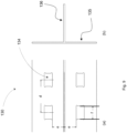
- FIG 3 shows a fastening system 100 according to the first embodiment with embedded facade elements 150 on a wall 160 in a three-dimensional representation.
- On the wall 160 support profiles 130 are attached at regular intervals.
- Fastening shells 120 are attached to the supporting profiles 130 by means of fastening elements 110, in which facade elements 150 are embedded.
- the fastening element 110 is realized by a fastening clamp 110 .
- the fastening clip 110 can be manufactured much more cheaply than the fastening element of the first embodiment.
- the fastening clamp 110 protrudes with a first fastening clamp leg 115 and a second fastening clamp leg 117 through openings 124, 134 in the connecting web of the fastening shell 120 and the support profile 130.
- the two fastening leg sections 115, 117 are of different lengths in the exemplary embodiment shown, which makes handling easier the assembly allows.
- the invention can also be implemented with fastening sections 115, 117 of the same length.
- the two openings 124 in the fastening shell connecting web 113 have a distance b, measured between the respective inner edge.
- the two openings 134 in the support profile 130 have a distance a, measured between the respective inner edge.
- the two fastening clip legs 115, 117 have a contour which forms an undercut in relation to the openings 124, 134 in the fastening shell connecting web 123 and the support profile 130.
- FIG 5 shows a fastening clamp 110 of the fastening system 100 according to the invention of the second embodiment in a three-dimensional representation.
- the fastening clamp 110 has a fastening clamp connecting web 113 which has a first fastening clamp leg 111 and a second fastening clamp leg 112 at its ends.
- the transitions between the fastening clip connecting web 113 and the one first fastening clip leg 111 and the second fastening clip leg 112 are provided with radii.
- the fastening clip connecting web 113 of this further embodiment is provided with a prestress, ie provided with a cambering with the dimension i compared to the straight course from the second embodiment.
- the dimension i can be less than 1 mm, for example.
- the camber points in the direction of the legs 111, 112. This prestressing removes the tolerance in the connection that is important for assembly, so that the fastening shell 120 fastened to the supporting profile 130 with the fastening clamp 113 of this embodiment sits on the supporting profile 130 without shaking.
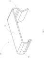
- the fastening shell 120 has a fastening shell connecting web 123 and a first fastening shell limb 121 and a second fastening shell limb 122 .
- the legs 121, 122 of the fastening shell are of different lengths, with the first leg 121 of the fastening shell having a bevel pointing towards the second leg of the fastening shell.
- the geometry of the fastening shell 120 is thus adapted to the geometry of a facade element 150 (not shown), so that the facade element 150 can be received geometrically in the fastening shell 120 .
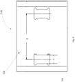
- FIG. 8 shows a fastening shell 120 of the fastening system 100 according to the invention of the second embodiment in a plan view.
- Two openings 124 are arranged in the fastening shell connecting web 123, each of which has a width h, the center-to-center spacing of the openings 124 having the dimension g.
- FIG. 9 shows a section of a support profile 130 of the fastening system 100 according to the invention of the second embodiment, with FIG Figure 8(a) a top view and in Figure 8(b) the view of an end face is shown.
- the support profile 130 has a flat profile with openings 134 arranged in a grid.
- the flat profile in the embodiment shown is the horizontal leg 135 of a T-profile.
- the center distance between the openings 134 in the support profile 130 is dimension d, the width of the openings 134 in the supporting profile 130 being dimension f.
- a internal length of the fastening clip connecting web 113
- b internal distance between two adjacent openings 124 in the fastening shell connecting web 123
- d center distance of the openings 134 in the support profile 130
- f width of an opening 134 in the support profile 130
- g center distance of the openings 124 in the fastening shell 120
- h width of an opening 124 in the fastening shell 120
- the mounting bracket 110 can thus be inserted with its legs 111, 112 into the mounting shell 120 and the support profile 130 in such a way that it connects the mounting shell 120 to the support profile 130 in a vibration-resistant and play-free manner.
- a facade element 150 embedded in the mounting shell 120 is also connected to the support profile 130 via the fastening clamp 110 without play and without shaking.
- the support profile 130 is as in Figure 8(b) embodied, for example, as a T-profile with a horizontal leg 135 and a vertical leg 136, it being connectable with its vertical leg 136 to a wall 160, so that a façade element can be mounted on a wall 160 without vibration and play via the fastening system 100.
Landscapes
- Engineering & Computer Science (AREA)
- Architecture (AREA)
- Civil Engineering (AREA)
- Structural Engineering (AREA)
- Finishing Walls (AREA)
Claims (9)
- Système de fixation (100), comportant un profilé porteur (130) muni d'ajours (134), le système de fixation (100) comportant par ailleurs un clip de fixation (110) en tant qu'élément de fixation (110), le clip de fixation (110) comportant une barrette d'assemblage (113) de clip de fixation, la dimension intérieure de la longueur a dans la barrette d'assemblage (113) de clip de fixation étant égale à la différence entre l'entraxe d des ajours (134) dans le profilé porteur (130) et la largeur f des ajours (134) dans le profilé porteur (130),
caractérisé
en ce que le système de fixation (100) comporte par ailleurs une coque de fixation (120) munie d'ajours (124), la dimension intérieure de la longueur a dans la barrette d'assemblage (113) de clip de fixation étant supérieure ou égale à la différence entre l'entraxe g des ajours (124) dans la coque de fixation (120) et la largeur h des ajours (124) dans la coque de fixation (120). - Système de fixation (100) selon l'une quelconque des revendications précédentes,
caractérisé
en ce que le système de fixation (100) comporte exactement trois éléments. - Système de fixation (100) selon l'une quelconque des revendications précédentes,
caractérisé
en ce que le profilé porteur (130), la coque de fixation (120) et le clip de fixation (110) comportent une matière métallique. - Système de fixation (100) selon l'une quelconque des revendications précédentes,
caractérisé
en ce que le clip de fixation (110) est fabriqué en un acier à ressort. - Système de fixation (100) selon l'une quelconque des revendications précédentes,
caractérisé
en ce que la coque de fixation (120) comporte la matière aluminium. - Système de fixation (100) selon l'une quelconque des revendications précédentes,
caractérisé
en ce que le profilé porteur (130) comporte la matière aluminium. - Système de fixation (100) selon l'une quelconque des revendications précédentes,
caractérisé
en ce que le profilé porteur (130) comporte un profilé plat muni d'ajours (134) placés selon une trame. - Procédé, destiné à fixer un élément de façade (150) sur un mur (160) à l'aide du système de fixation (100) selon l'une quelconque des revendications précédentes, le clip de fixation (110) comportant des branches (111, 112),
caractérisé par les étapes consistant à- insérer le clip de fixation (110) dans la coque de fixation (120), de telle sorte que les branches (111, 112) du clip de fixation (110) saillissent hors de la coque de fixation (120),- assembler la coque de fixation (120) avec le profilé porteur (130), en insérant les branches (111, 112) du clip de fixation (110) saillant hors de la coque de fixation (120) dans les ajours (134) correspondants dans le profilé porteur (130) préalablement fixé sur le mur (160),- incorporer un élément de façade (150) dans la coque de fixation (120) assemblée avec le profilé porteur (130). - Utilisation du système de fixation (100), correspondant à l'une quelconque des revendications 1 à 7 pour la fixation d'un élément de façade (150) sur un mur (160).
Applications Claiming Priority (2)
| Application Number | Priority Date | Filing Date | Title |
|---|---|---|---|
| DE102019123162 | 2019-08-29 | ||
| PCT/EP2020/074141 WO2021038081A1 (fr) | 2019-08-29 | 2020-08-28 | Système de fixation |
Publications (3)
| Publication Number | Publication Date |
|---|---|
| EP4022147A1 EP4022147A1 (fr) | 2022-07-06 |
| EP4022147B1 true EP4022147B1 (fr) | 2023-07-05 |
| EP4022147C0 EP4022147C0 (fr) | 2023-07-05 |
Family
ID=72292533
Family Applications (1)
| Application Number | Title | Priority Date | Filing Date |
|---|---|---|---|
| EP20764641.5A Active EP4022147B1 (fr) | 2019-08-29 | 2020-08-28 | Système de fixation |
Country Status (3)
| Country | Link |
|---|---|
| EP (1) | EP4022147B1 (fr) |
| DE (1) | DE102019128488A1 (fr) |
| WO (1) | WO2021038081A1 (fr) |
Citations (2)
| Publication number | Priority date | Publication date | Assignee | Title |
|---|---|---|---|---|
| DE102005019977B4 (de) * | 2005-04-27 | 2007-12-27 | Deutsche Steinzeug Cremer & Breuer Ag | Fassadensystem aus keramischen Fassadenplatten zum Einsatz als vorgehängte hinterlüftete Fassade an einer tragenden Bauwerkswand |
| CN109680895A (zh) * | 2019-02-13 | 2019-04-26 | 重庆工业职业技术学院 | 一种插卡方式固定上钩头的插入式挂件 |
Family Cites Families (4)
| Publication number | Priority date | Publication date | Assignee | Title |
|---|---|---|---|---|
| US2116530A (en) * | 1935-06-01 | 1938-05-10 | Grabler Mfg Company | Building structure |
| DE7047060U (de) * | 1970-12-21 | 1971-05-19 | Hunter Douglas | Paneelclip |
| EP0016291A1 (fr) * | 1979-02-22 | 1980-10-01 | Georges Emile Prost | Dispositifs d'assemblage et de fixation d'éléments de construction industrielles et bâtiments obtenus par montage avec mise en oeuvre de ces dispositifs |
| CH635892A5 (en) * | 1979-04-10 | 1983-04-29 | Hunter Douglas Ind Bv | Surfacing for ceilings or walls, in particular for facades |
-
2019
- 2019-10-22 DE DE102019128488.0A patent/DE102019128488A1/de active Pending
-
2020
- 2020-08-28 EP EP20764641.5A patent/EP4022147B1/fr active Active
- 2020-08-28 WO PCT/EP2020/074141 patent/WO2021038081A1/fr unknown
Patent Citations (2)
| Publication number | Priority date | Publication date | Assignee | Title |
|---|---|---|---|---|
| DE102005019977B4 (de) * | 2005-04-27 | 2007-12-27 | Deutsche Steinzeug Cremer & Breuer Ag | Fassadensystem aus keramischen Fassadenplatten zum Einsatz als vorgehängte hinterlüftete Fassade an einer tragenden Bauwerkswand |
| CN109680895A (zh) * | 2019-02-13 | 2019-04-26 | 重庆工业职业技术学院 | 一种插卡方式固定上钩头的插入式挂件 |
Also Published As
| Publication number | Publication date |
|---|---|
| EP4022147C0 (fr) | 2023-07-05 |
| EP4022147A1 (fr) | 2022-07-06 |
| WO2021038081A1 (fr) | 2021-03-04 |
| DE102019128488A1 (de) | 2021-03-04 |
Similar Documents
| Publication | Publication Date | Title |
|---|---|---|
| EP1288387B1 (fr) | Rail de montage profilé | |
| DE202005021538U1 (de) | Abdeckvorrichtung für Fußbodenbeläge | |
| DE8604004U1 (de) | Demontierbare Sportbodenbelagbahn | |
| DE202018103991U1 (de) | Tragschiene als Systemschiene für den Trockenbau | |
| DE102018126669A1 (de) | Verkleidungssystem für eine Wand, Anordnung des Verkleidungssystems und Verfahren zur Montage des Verkleidungssystems | |
| EP4022147B1 (fr) | Système de fixation | |
| DE102005044322B4 (de) | Haltekonstruktion für Fassadenplatten, sowie Gebäudefassade | |
| EP2496777B1 (fr) | Système de positionnement de profilés suspendus en pose à sec | |
| DE112017003921T5 (de) | Verankerungsvorrichtung für belüftete Vorhangfassaden | |
| EP0971084B1 (fr) | Cale pour coffrage | |
| DE10300651B3 (de) | Sturmklammer | |
| DE20206281U1 (de) | Tragprofil für mehrere C-Profilschienen | |
| DE20122280U1 (de) | Fugenlehre | |
| DE202020105060U1 (de) | System zur lösbaren Verbindung von Bauteilen | |
| DE2752963A1 (de) | Wand- oder deckenkonstruktion | |
| DE4344923C2 (de) | Haltevorrichtung für Heizungsrohre | |
| DE102023116787A1 (de) | Einhängeelement für Ankerplatte eines Seitenunfallschutzes, Ankerplatte für Seitenunfallschutz sowie System aus Ankerplatte und Einhängeelement | |
| DE102023000634A1 (de) | Geländertragprofil | |
| DE102023117292A1 (de) | Traverse | |
| EP1344880A2 (fr) | Elément de construction profilé à usage en tant qu'élément de clôture | |
| DE3130755C2 (de) | Halterung zum Befestigen von Klinkern auf einer Wand | |
| DE202023100433U1 (de) | Montagesystem | |
| AT501795B1 (de) | Einrichtung für die reparatur oder erweiterung eines dachs | |
| DE202023102335U1 (de) | Paneel mit einer einen Dämmstoff aufweisenden Kernschicht | |
| DE29814097U1 (de) | Mehrteilige Fassadenklammer |
Legal Events
| Date | Code | Title | Description |
|---|---|---|---|
| STAA | Information on the status of an ep patent application or granted ep patent |
Free format text: STATUS: UNKNOWN |
|
| STAA | Information on the status of an ep patent application or granted ep patent |
Free format text: STATUS: THE INTERNATIONAL PUBLICATION HAS BEEN MADE |
|
| PUAI | Public reference made under article 153(3) epc to a published international application that has entered the european phase |
Free format text: ORIGINAL CODE: 0009012 |
|
| STAA | Information on the status of an ep patent application or granted ep patent |
Free format text: STATUS: REQUEST FOR EXAMINATION WAS MADE |
|
| 17P | Request for examination filed |
Effective date: 20220224 |
|
| AK | Designated contracting states |
Kind code of ref document: A1 Designated state(s): AL AT BE BG CH CY CZ DE DK EE ES FI FR GB GR HR HU IE IS IT LI LT LU LV MC MK MT NL NO PL PT RO RS SE SI SK SM TR |
|
| DAV | Request for validation of the european patent (deleted) | ||
| DAX | Request for extension of the european patent (deleted) | ||
| GRAP | Despatch of communication of intention to grant a patent |
Free format text: ORIGINAL CODE: EPIDOSNIGR1 |
|
| STAA | Information on the status of an ep patent application or granted ep patent |
Free format text: STATUS: GRANT OF PATENT IS INTENDED |
|
| INTG | Intention to grant announced |
Effective date: 20230126 |
|
| GRAS | Grant fee paid |
Free format text: ORIGINAL CODE: EPIDOSNIGR3 |
|
| GRAA | (expected) grant |
Free format text: ORIGINAL CODE: 0009210 |
|
| STAA | Information on the status of an ep patent application or granted ep patent |
Free format text: STATUS: THE PATENT HAS BEEN GRANTED |
|
| AK | Designated contracting states |
Kind code of ref document: B1 Designated state(s): AL AT BE BG CH CY CZ DE DK EE ES FI FR GB GR HR HU IE IS IT LI LT LU LV MC MK MT NL NO PL PT RO RS SE SI SK SM TR |
|
| P01 | Opt-out of the competence of the unified patent court (upc) registered |
Effective date: 20230526 |
|
| REG | Reference to a national code |
Ref country code: CH Ref legal event code: EP |
|
| REG | Reference to a national code |
Ref country code: AT Ref legal event code: REF Ref document number: 1584982 Country of ref document: AT Kind code of ref document: T Effective date: 20230715 |
|
| REG | Reference to a national code |
Ref country code: DE Ref legal event code: R096 Ref document number: 502020004068 Country of ref document: DE |
|
| REG | Reference to a national code |
Ref country code: IE Ref legal event code: FG4D Free format text: LANGUAGE OF EP DOCUMENT: GERMAN |
|
| U01 | Request for unitary effect filed |
Effective date: 20230713 |
|
| U07 | Unitary effect registered |
Designated state(s): AT BE BG DE DK EE FI FR IT LT LU LV MT NL PT SE SI Effective date: 20230724 |
|
| P04 | Withdrawal of opt-out of the competence of the unified patent court (upc) registered |
Effective date: 20230719 |
|
| REG | Reference to a national code |
Ref country code: LT Ref legal event code: MG9D |
|
| PGFP | Annual fee paid to national office [announced via postgrant information from national office to epo] |
Ref country code: CH Payment date: 20230902 Year of fee payment: 4 |
|
| U20 | Renewal fee paid [unitary effect] |
Year of fee payment: 4 Effective date: 20231103 |
|
| PG25 | Lapsed in a contracting state [announced via postgrant information from national office to epo] |
Ref country code: GR Free format text: LAPSE BECAUSE OF FAILURE TO SUBMIT A TRANSLATION OF THE DESCRIPTION OR TO PAY THE FEE WITHIN THE PRESCRIBED TIME-LIMIT Effective date: 20231006 |
|
| PG25 | Lapsed in a contracting state [announced via postgrant information from national office to epo] |
Ref country code: ES Free format text: LAPSE BECAUSE OF FAILURE TO SUBMIT A TRANSLATION OF THE DESCRIPTION OR TO PAY THE FEE WITHIN THE PRESCRIBED TIME-LIMIT Effective date: 20230705 |
|
| PG25 | Lapsed in a contracting state [announced via postgrant information from national office to epo] |
Ref country code: IS Free format text: LAPSE BECAUSE OF FAILURE TO SUBMIT A TRANSLATION OF THE DESCRIPTION OR TO PAY THE FEE WITHIN THE PRESCRIBED TIME-LIMIT Effective date: 20231105 |
|
| PG25 | Lapsed in a contracting state [announced via postgrant information from national office to epo] |
Ref country code: RS Free format text: LAPSE BECAUSE OF FAILURE TO SUBMIT A TRANSLATION OF THE DESCRIPTION OR TO PAY THE FEE WITHIN THE PRESCRIBED TIME-LIMIT Effective date: 20230705 Ref country code: NO Free format text: LAPSE BECAUSE OF FAILURE TO SUBMIT A TRANSLATION OF THE DESCRIPTION OR TO PAY THE FEE WITHIN THE PRESCRIBED TIME-LIMIT Effective date: 20231005 Ref country code: IS Free format text: LAPSE BECAUSE OF FAILURE TO SUBMIT A TRANSLATION OF THE DESCRIPTION OR TO PAY THE FEE WITHIN THE PRESCRIBED TIME-LIMIT Effective date: 20231105 Ref country code: HR Free format text: LAPSE BECAUSE OF FAILURE TO SUBMIT A TRANSLATION OF THE DESCRIPTION OR TO PAY THE FEE WITHIN THE PRESCRIBED TIME-LIMIT Effective date: 20230705 Ref country code: GR Free format text: LAPSE BECAUSE OF FAILURE TO SUBMIT A TRANSLATION OF THE DESCRIPTION OR TO PAY THE FEE WITHIN THE PRESCRIBED TIME-LIMIT Effective date: 20231006 Ref country code: ES Free format text: LAPSE BECAUSE OF FAILURE TO SUBMIT A TRANSLATION OF THE DESCRIPTION OR TO PAY THE FEE WITHIN THE PRESCRIBED TIME-LIMIT Effective date: 20230705 |
|
| PG25 | Lapsed in a contracting state [announced via postgrant information from national office to epo] |
Ref country code: PL Free format text: LAPSE BECAUSE OF FAILURE TO SUBMIT A TRANSLATION OF THE DESCRIPTION OR TO PAY THE FEE WITHIN THE PRESCRIBED TIME-LIMIT Effective date: 20230705 |
|
| REG | Reference to a national code |
Ref country code: DE Ref legal event code: R097 Ref document number: 502020004068 Country of ref document: DE |
|
| PG25 | Lapsed in a contracting state [announced via postgrant information from national office to epo] |
Ref country code: SM Free format text: LAPSE BECAUSE OF FAILURE TO SUBMIT A TRANSLATION OF THE DESCRIPTION OR TO PAY THE FEE WITHIN THE PRESCRIBED TIME-LIMIT Effective date: 20230705 Ref country code: RO Free format text: LAPSE BECAUSE OF FAILURE TO SUBMIT A TRANSLATION OF THE DESCRIPTION OR TO PAY THE FEE WITHIN THE PRESCRIBED TIME-LIMIT Effective date: 20230705 Ref country code: CZ Free format text: LAPSE BECAUSE OF FAILURE TO SUBMIT A TRANSLATION OF THE DESCRIPTION OR TO PAY THE FEE WITHIN THE PRESCRIBED TIME-LIMIT Effective date: 20230705 Ref country code: SK Free format text: LAPSE BECAUSE OF FAILURE TO SUBMIT A TRANSLATION OF THE DESCRIPTION OR TO PAY THE FEE WITHIN THE PRESCRIBED TIME-LIMIT Effective date: 20230705 Ref country code: MC Free format text: LAPSE BECAUSE OF FAILURE TO SUBMIT A TRANSLATION OF THE DESCRIPTION OR TO PAY THE FEE WITHIN THE PRESCRIBED TIME-LIMIT Effective date: 20230705 |
|
| PLBE | No opposition filed within time limit |
Free format text: ORIGINAL CODE: 0009261 |
|
| STAA | Information on the status of an ep patent application or granted ep patent |
Free format text: STATUS: NO OPPOSITION FILED WITHIN TIME LIMIT |
|
| REG | Reference to a national code |
Ref country code: IE Ref legal event code: MM4A |
|
| 26N | No opposition filed |
Effective date: 20240408 |
|
| PG25 | Lapsed in a contracting state [announced via postgrant information from national office to epo] |
Ref country code: IE Free format text: LAPSE BECAUSE OF NON-PAYMENT OF DUE FEES Effective date: 20230828 |
|
| PG25 | Lapsed in a contracting state [announced via postgrant information from national office to epo] |
Ref country code: IE Free format text: LAPSE BECAUSE OF NON-PAYMENT OF DUE FEES Effective date: 20230828 |