EP4021267B1 - Flache waschmaschine und methode - Google Patents
Flache waschmaschine und methode Download PDFInfo
- Publication number
- EP4021267B1 EP4021267B1 EP20765058.1A EP20765058A EP4021267B1 EP 4021267 B1 EP4021267 B1 EP 4021267B1 EP 20765058 A EP20765058 A EP 20765058A EP 4021267 B1 EP4021267 B1 EP 4021267B1
- Authority
- EP
- European Patent Office
- Prior art keywords
- washing
- suction
- suction heads
- planar
- washing machine
- Prior art date
- Legal status (The legal status is an assumption and is not a legal conclusion. Google has not performed a legal analysis and makes no representation as to the accuracy of the status listed.)
- Active
Links
Images
Classifications
-
- A—HUMAN NECESSITIES
- A47—FURNITURE; DOMESTIC ARTICLES OR APPLIANCES; COFFEE MILLS; SPICE MILLS; SUCTION CLEANERS IN GENERAL
- A47L—DOMESTIC WASHING OR CLEANING; SUCTION CLEANERS IN GENERAL
- A47L11/00—Machines for cleaning floors, carpets, furniture, walls, or wall coverings
- A47L11/02—Floor surfacing or polishing machines
- A47L11/20—Floor surfacing or polishing machines combined with vacuum cleaning devices
- A47L11/201—Floor surfacing or polishing machines combined with vacuum cleaning devices with supply of cleaning agents
-
- B—PERFORMING OPERATIONS; TRANSPORTING
- B08—CLEANING
- B08B—CLEANING IN GENERAL; PREVENTION OF FOULING IN GENERAL
- B08B3/00—Cleaning by methods involving the use or presence of liquid or steam
- B08B3/02—Cleaning by the force of jets or sprays
- B08B3/024—Cleaning by means of spray elements moving over the surface to be cleaned
-
- B—PERFORMING OPERATIONS; TRANSPORTING
- B08—CLEANING
- B08B—CLEANING IN GENERAL; PREVENTION OF FOULING IN GENERAL
- B08B3/00—Cleaning by methods involving the use or presence of liquid or steam
- B08B3/04—Cleaning involving contact with liquid
- B08B3/041—Cleaning travelling work
-
- D—TEXTILES; PAPER
- D06—TREATMENT OF TEXTILES OR THE LIKE; LAUNDERING; FLEXIBLE MATERIALS NOT OTHERWISE PROVIDED FOR
- D06B—TREATING TEXTILE MATERIALS USING LIQUIDS, GASES OR VAPOURS
- D06B1/00—Applying liquids, gases or vapours onto textile materials to effect treatment, e.g. washing, dyeing, bleaching, sizing or impregnating
- D06B1/02—Applying liquids, gases or vapours onto textile materials to effect treatment, e.g. washing, dyeing, bleaching, sizing or impregnating by spraying or projecting
-
- D—TEXTILES; PAPER
- D06—TREATMENT OF TEXTILES OR THE LIKE; LAUNDERING; FLEXIBLE MATERIALS NOT OTHERWISE PROVIDED FOR
- D06F—LAUNDERING, DRYING, IRONING, PRESSING OR FOLDING TEXTILE ARTICLES
- D06F11/00—Washing machines using rollers, e.g. of the mangle type
-
- D—TEXTILES; PAPER
- D06—TREATMENT OF TEXTILES OR THE LIKE; LAUNDERING; FLEXIBLE MATERIALS NOT OTHERWISE PROVIDED FOR
- D06F—LAUNDERING, DRYING, IRONING, PRESSING OR FOLDING TEXTILE ARTICLES
- D06F17/00—Washing machines having receptacles, stationary for washing purposes, wherein the washing action is effected solely by circulation or agitation of the washing liquid
- D06F17/04—Washing machines having receptacles, stationary for washing purposes, wherein the washing action is effected solely by circulation or agitation of the washing liquid solely by water jets
-
- D—TEXTILES; PAPER
- D06—TREATMENT OF TEXTILES OR THE LIKE; LAUNDERING; FLEXIBLE MATERIALS NOT OTHERWISE PROVIDED FOR
- D06F—LAUNDERING, DRYING, IRONING, PRESSING OR FOLDING TEXTILE ARTICLES
- D06F34/00—Details of control systems for washing machines, washer-dryers or laundry dryers
- D06F34/14—Arrangements for detecting or measuring specific parameters
- D06F34/18—Condition of the laundry, e.g. nature or weight
-
- D—TEXTILES; PAPER
- D06—TREATMENT OF TEXTILES OR THE LIKE; LAUNDERING; FLEXIBLE MATERIALS NOT OTHERWISE PROVIDED FOR
- D06F—LAUNDERING, DRYING, IRONING, PRESSING OR FOLDING TEXTILE ARTICLES
- D06F35/00—Washing machines, apparatus, or methods not otherwise provided for
-
- D—TEXTILES; PAPER
- D06—TREATMENT OF TEXTILES OR THE LIKE; LAUNDERING; FLEXIBLE MATERIALS NOT OTHERWISE PROVIDED FOR
- D06F—LAUNDERING, DRYING, IRONING, PRESSING OR FOLDING TEXTILE ARTICLES
- D06F39/00—Details of washing machines not specific to a single type of machines covered by groups D06F9/00 - D06F27/00
- D06F39/02—Devices for adding soap or other washing agents
- D06F39/022—Devices for adding soap or other washing agents in a liquid state
-
- D—TEXTILES; PAPER
- D06—TREATMENT OF TEXTILES OR THE LIKE; LAUNDERING; FLEXIBLE MATERIALS NOT OTHERWISE PROVIDED FOR
- D06G—MECHANICAL OR PRESSURE CLEANING OF CARPETS, RUGS, SACKS, HIDES, OR OTHER SKIN OR TEXTILE ARTICLES OR FABRICS; TURNING INSIDE-OUT FLEXIBLE TUBULAR OR OTHER HOLLOW ARTICLES
- D06G1/00—Beating, brushing, or otherwise mechanically cleaning or pressure cleaning carpets, rugs, sacks, hides, or other skin or textile articles or fabrics
-
- A—HUMAN NECESSITIES
- A47—FURNITURE; DOMESTIC ARTICLES OR APPLIANCES; COFFEE MILLS; SPICE MILLS; SUCTION CLEANERS IN GENERAL
- A47L—DOMESTIC WASHING OR CLEANING; SUCTION CLEANERS IN GENERAL
- A47L11/00—Machines for cleaning floors, carpets, furniture, walls, or wall coverings
- A47L11/34—Machines for treating carpets in position by liquid, foam, or vapour, e.g. by steam
-
- D—TEXTILES; PAPER
- D06—TREATMENT OF TEXTILES OR THE LIKE; LAUNDERING; FLEXIBLE MATERIALS NOT OTHERWISE PROVIDED FOR
- D06F—LAUNDERING, DRYING, IRONING, PRESSING OR FOLDING TEXTILE ARTICLES
- D06F43/00—Dry-cleaning apparatus or methods using volatile solvents
- D06F43/002—Spotting apparatus
Definitions
- the invention relates to a planar washing machine and to a method of washing rugs and carpets.
- Planar washing machines have been developed for washing different kind of planar separate textile products. Such machines are used for example in self-service laundromats.
- the present solutions have shown some disadvantages in their washing units.
- Documents US-4182001-A , US-5784754-A and US-2005/177972-A1 disclose washing units for surface cleaning devices.
- An object of the invention is to provide a novel and improved washing machine and solution for washing separate textile products in a planar washing machine.
- planar washing machine according to the invention is characterized by the characterizing features of the independent apparatus claim.
- the method according to the invention is characterized by the characterizing features of the independent method claim.
- a washing machine intended for washing separate planar textile products is provided with one or more washing units.
- the washing unit comprises a frame, at least two rotating suction heads and at least one washing nozzle for feeding washing liquid to the textile product being washed.
- the mentioned washing nozzle is located between the mentioned rotating suction heads. In other words, only the suction heads are rotated and the one or more washing nozzles are immovable relative to the frame of the washing unit.
- An advantage of the disclosed solution is that when the suction heads are arranged separately relative to the washing nozzles, the structure of the washing unit may be simple and robust. For example, there is no need to arrange rotating feed connections to the washing fluid conduits and the suction heads may be designed solely for the suction purpose.
- washing fluid may also refer to a rinsing fluid or agent. This way the washing nozzles may spray not only the washing agent but also the rinsing fluid towards the textile product being washed. Then the suction head may remove both the washing and rinsing agent from the textile product.
- the washing unit is intended for washing rugs and carpets.
- the rug is a separate piece of thick cloth which is not fixed to a floor.
- the term "carpet" is also used for such separate textile floor coverings.
- the washing nozzle is located at a distance from the front end or face of the suction head facing towards the textile product being washed.
- the washing liquid is fed from a distance towards the textile product and the suction head is in physical contact with the textile product.
- the mentioned at least two suction heads are arranged to be rotated into opposite directions relative to each other.
- the two adjacent suction heads are rotated into opposite directions, then their rotating forces directed to the textile product being washed cancel each other and no wrinkles are formed.
- the opposing rotating suction heads may also facilitate the cleaning process, and further, entanglement of long hair and yarns around the rotating components may also be avoided.
- the washing unit comprises at least two washing rows, wherein each washing row comprises two suction heads and at least one washing nozzle between the suctions heads. Then the washing unit comprises at least four suction heads and at least two washing nozzles. Number of washing rows may also be more than two, if needed.
- An advantage of this embodiment is that the washing unit covers a wider range and washing capacity may be increased.
- the suction head comprises a face, which is intended to be directed towards the textile product being washed.
- the face of the suction head is round and comprises a narrow longitudinal suction opening passing transversally through a rotation axle of the suction head.
- the narrow longitudinal suction opening intensifies the suction effect and may cover the entire suction head when being rotated.
- the above mentioned suction opening of the face of the suction head comprises a central part and two transverse branches which are located at distal ends of the central part and are facing into opposite directions relative to each other. According to practical tests the disclosed specific shape of the suction opening is found to be effective.
- the suction head is configured to be rotated so that the mentioned branches are directed towards the rotation direction of the suction head.
- the aim of the braches is to intensify the suction and to prevent splashing of the washing fluid.
- the washing unit is provided with a frequency converted electric motor for driving the rotating suction heads.
- rotation speed and torque of the frequency converted electric motor can be controlled steplessly. Further, there is no need for separate gearing, whereby weight of the washing system may be reasonable and the structure may be simple.
- the rotation movement generated by the electric motor is transmitted to all suction heads by means of a power transmission based on a toothed belt.
- the washing unit is provided with an electric motor for providing driving of the rotating suction heads in constant speed.
- suitable rotation speed may be determined beforehand.
- the rotation speed may be selected in relation to the feed speed of the textile product and the movement speed of the washing unit, for example.
- the washing unit comprises bearing means for coupling it to a linear guide surface of the washing machine and to thereby allow the washing unit to be moved linearly under control of the linear guide surface.
- an elongated transverse guide bar is serving as the linear guide surface.
- the frame of the washing unit comprises at least two rollers on a side facing towards the textile product and configured to be set against the textile product during the washing process.
- the washing unit is provided with at least two sensing devices for sensing longitudinal edges of the textile product being washed.
- the sensing device may be in physical contact with the textile product, or alternatively it may detect the edge by using remote sensing techniques.
- the remote sensing system may comprise ultrasonic sensors or laser sensors, for example.
- the washing nozzle is mounted immovably relative to the frame of the washing unit. This way structure and mounting of the washing nozzle may be simple and durable.
- the washing nozzle may be mounted to the frame and it may be located at a distance from the front faces of the suction heads.
- the several washing nozzles are mounted to gaps remaining between the adjacent suction heads.
- the washing nozzles are then well protected and the washing jets are effectively directed towards the textile product being washed.
- the washing nozzle is configured to produce a narrow fan-like washing agent jet, which is directed against the textile product.
- the fan-like jet has wide coverage and still the washing nozzle may be simple.
- width of the above mentioned fan-like washing agent jet may correspond to a diameter of the rotating suction head. Then the washing agent jet may cover the entire width of the washing unit.
- the fan-like washing agent jets may be configured to partly overlap. This way the fan-like jets cover together a wide range.
- the solution relates to a planar washing machine for washing separate planar textile products.
- the washing machine may comprise: a standing body configured to be mounted on a floor; a feed opening for feeding the textile product into the washing machine; transfer means for transferring the textile product in the washing machine in a feed direction; at least one washing unit for washing the textile product inside the washing machine; and wherein the washing unit is configured to be driven in a reciprocating manner in a transverse direction relative to the feed direction, whereby the washing unit is moved between longitudinal edges of the textile product.
- the textile product is fed during a washing cycle in the feed direction relative to the washing unit by means of the transfer means.
- the washing unit is not moved in the feed direction.
- the washing unit is driven perpendicularly relative to the feed direction.
- the washing unit is as it is disclosed above in this document.
- the washing machine comprises at least one guide surface direction of which is perpendicular to the feed direction and the washing unit is provided with bearings for supporting the washing unit to the guide surface.
- the washing unit comprises two rows of suction heads transverse to the feed direction.
- Each row comprises adjacent two suction heads, whereby total number of rotating suction heads is four.
- Between the adjacent two suction heads of each row is a gap provided with at least one washing nozzle. Furthermore, the adjacent suction heads of each row are rotated into opposite directions relative to each other so that their direction of rotation is towards the mentioned gap.
- the solution relates to a method of washing separate planar textile products with a planar washing machine.
- the method comprises: feeding an end of textile product into a feed opening of the washing machine; feeding the textile product in a feed direction with transfer means; washing the textile product by means of at least washing unit and moving the washing unit in a transverse direction relative to the feed direction during the washing; directing a washing fluid jet from at least one washing nozzle of the washing unit towards a surface of the textile product; and directing suction from at least one rotating suction head to the surface of the textile product in order to remove moisture form the textile product.
- the method further comprises providing the washing unit with at least two separate rotating suction heads and directing the washing fluid jet from at least one non-rotating separate washing nozzle which is located in a gap between adjacent rotating suction heads.
- the disclosed method comprises rotating the adjacent suction heads into opposite directions relative to each other and arranging faces of the rotating suction heads into physical contact with the textile product in order to intensify the washing.
- the disclosed method comprises rotating the adjacent suction heads into opposite directions relative to each other and providing faces of the suction heads with shaped suction openings in order to prevent splashing of the washing fluid.
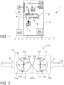
- FIG. 1 shows a planar washing machine 1 for washing planar textile products 23 such as rugs or similar furnishing textiles.
- the washing machine 1 comprises a body 3.
- the textile product 23 may be fed into the washing machine 1 through a feed opening 4.
- the actual washing may be performed by means of a washing unit WU.
- the washing unit WU may comprise one or more washing nozzles and two or more suction heads. Washing agent or washing liquid is fed with high pressure from a washing liquid unit LU, and a drying suction may be formed with a suction unit or source SU.
- the operation of the washing machine 1 may be controlled by a control unit CU.
- the control unit CU may automatically control the suction of a holding device 6, hatch 10, feeding or transfer means 8, washing unit WU and generally the entire work cycle of the washing machine 1.
- the washing machine 1 washes the rug with the aid of one or more washing agent jets and two or more rotating suction heads.
- the washing agent used in the washing is water to which washing agent may have been mixed. Further, the washing machine 1 sucks off the water left in the rug after the washing, drying the rug so that when the rug is taken out of the washing machine, no water will run out of it and it will dry fast.
- the disclosed washing machine 1 may be installed in a launderette where the customers themselves use the washing machine.
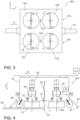
- FIG. 2 discloses a washing unit WU comprising a frame 12 and two rotating suction heads 13.
- a washing nozzle 14 is located between the suction heads 13a, 13b.
- the washing unit WU is provided with bearings 15 so that is can be moved A along a guide surface 16.
- the suction heads 13a, 13b may be rotated into opposite directions R1 and R2.
- the suction heads 13 are rotated R relative to rotation axles RA of the suction heads 13.
- the suction head 13 comprises a face 17 provided with a suction opening 18.
- the suction opening 18 may comprise a longitudinal narrow central part 19 and two transverse branches 20a, 20b at distal ends of the suction opening 18.
- the branches 20 may be facing into opposite directions.
- Figure 3 discloses a washing unit WU comprising four rotating suction heads 13a - 13d, and two nozzles 14a and 14b for feeding washing and rinsing fluids.
- the suction heads 13a and 13b are arranged to form a first row 21a and the suctions heads 13c and 13d are arranged to form a second row 21b. This way, the washing unit is wider in a feed direction y. Further, the suction heads 13 of both rows 21 are rotated into opposite directions and the all comprise narrow suction openings 18.
- Figure 4 discloses a washing unit WU which is moved transversally to its right most extreme position where a washing nozzle 14 is at a longitudinal edge 22 of a textile product 23.
- the edges 22 can detected by means of a sensing device 24 and a control unit CU may control the movement A of the washing unit WU in response to received detection data.
- the sensing device 24 may comprise a contact element 25 for sensing the edge 22, or alternatively, there may be contactless sensors at opposite ends of the washing unit WU.
- a frame 12 may also be provided with rollers 26 facing towards the textile product 23 and configured to be set against the textile product 23 when the washing unit WU is lowered Z to the operational position.
- Suction heads 13 are supported to the frame 12 by means of bearings 27 and their upper parts are connected to suction conduits 28 for leading suction from a suction unit. There may be a rotating connection and seals 29 between the suction conduit 28 and the suction head 13.
- the suction heads 13 may be rotated with one common motor M.
- the motor M may be an electrical motor connected to the suction heads 13 by means of transmission means 30, such as toothed belt.
- the suction heads 13 may then be provided with corresponding toothed parts 31 on their outer surfaces.
- the washing nozzle 14 is located between the suction heads 13 and are positioned at a vertical distance from the textile product 23 and a face surface of the suction heads 13.
- the washing nozzle 14 is in fluid connection with a washing fluid conduit 32.
- the washing nozzle 14 may form a flushing jet J which may have fan-like configuration.
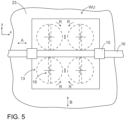
- Figure 5 discloses a washing unit WU movable A transversally x relative to a textile product 23 which is movable B in a feed direction y inside a planar washing machine.
- Rotating suction heads 13 are shown with broken lines.
- Suction openings 18 of the suction heads 13 may have slit-like configuration.
- the washing unit WU may comprise three or even more washing rows and dedicated washing nozzles between the suction heads. However, number of the washing nozzles may be greater as the number of the rows.
- the suction heads may be arranged to form a suction pattern 1*2, 2*2, 3*2 or 4*2 for example, wherein the first numeral indicates the number of the rows and the second numeral indicates that each row comprises two successive suctions heads.
Landscapes
- Engineering & Computer Science (AREA)
- Textile Engineering (AREA)
- Mechanical Engineering (AREA)
- Treatment Of Fiber Materials (AREA)
- Accessory Of Washing/Drying Machine, Commercial Washing/Drying Machine, Other Washing/Drying Machine (AREA)
Claims (14)
- Planarwaschmaschine (1) zum Waschen von getrennten planaren Textilerzeugnissen (23),
und wobei die Waschmaschine (1) umfasst:ein stehender Körper (3), der für die Montage auf einem Boden konfiguriert ist;eine Einfüllöffnung (4) zum Zuführen des Textilerzeugnisses (23) in die Waschmaschine (1);Transfermittel (8) zum Umsetzen (B) des Textilprodukts (23) in der Waschmaschine (1) in eine Zuführrichtung (y);mindestens eine Wascheinheit (WU) zum Waschen des Textilerzeugnisses (23) in der Waschmaschine (1);und wobei die Wascheinheit (WU) so konfiguriert ist, dass sie in hin- und hergehender Weise in einer Querrichtung (x) relativ zur Zuführrichtung (y) angetrieben wird, wobei die Wascheinheit (WU) zwischen Längskanten (22) des Textilprodukts (23) bewegt (A) wird;wobeidie Wascheinheit (WU) einen Rahmen (12), mindestens zwei rotierende Saugköpfe (13, 13a - 13d) und mindestens eine Waschdüse (14) zur Zuführung von Waschflüssigkeit aufweist und sich zwischen den genannten rotierenden Saugköpfen (13) befindet;und die mindestens eine Waschdüse (14, 14a, 14b) ist relativ zum Rahmen (12) der Wascheinheit (WU) unbeweglich. - Planarwaschmaschine nach Anspruch 1, wobei
die mindestens zwei Saugköpfe (13) so angeordnet sind, dass sie relativ zueinander in entgegengesetzte Richtungen rotiert werden (R, R1, R2). - Planarwaschmaschine nach Anspruch 1 oder 2, wobeidie Waschanlage (WU) mindestens zwei Waschreihen (21a, 21b) umfasst; undjede Waschreihe (21a, 21b) zwei Saugköpfe (13) und mindestens eine Waschdüse (14) zwischen den Saugköpfen (13) umfasst, wobei die Wascheinheit (WU) mindestens vier Saugköpfe (13) und mindestens zwei Waschdüsen (14) umfasst.
- Planarwaschmaschine nach einem der vorhergehenden Ansprüche 1 - 3, wobeider Saugkopf (13) weist eine Stirnseite (17) auf, die auf das zu waschende Textilerzeugnis (23) gerichtet sein soll;die Stirnseite (17) ist rund und weist eine schmale länglich Saugöffnung (18) auf, die quer durch eine Rotationsachse (RA) des Saugkopfes (13) verläuft.
- Planarwaschmaschine nach Anspruch 4, wobei
die Saugöffnung (18) der Stirnseite (17) des Saugkopfes (13) einen Mittelteil (19) und zwei Queräste (20A, 20B) umfasst, die sich an den distalen Enden des Mittelteils (19) befinden und zueinander in entgegengesetzte Richtungen ausgerichtet sind. - Planarwaschmaschine nach einem der vorhergehenden Ansprüche 1 - 5, wobei
die Wascheinheit (WU) mit einem frequenzumgerichteten Elektromotor (M) zum Antrieb der rotierenden Saugköpfe (13) ausgestattet ist. - Planarwaschmaschine nach einem der vorhergehenden Ansprüche 1 - 6, wobei
die Wascheinheit (WU) weist Lagermittel (15) auf, um sie mit einer Linearführungsfläche (16) der Waschmaschine (1) zu koppeln und dadurch eine lineare Bewegung(A) der Wascheinheit (WU) unter Kontrolle der Linearführungsfläche (16) zu ermöglichen. - Planarwaschmaschine nach einem der vorhergehenden Ansprüche 1 - 7, wobei
die Waschdüse (14) relativ zum Rahmen (12) der Wascheinheit (WU) unbeweglich montiert ist. - Planarwaschmaschine nach einem der vorhergehenden Ansprüche 1 - 8, wobei
die Waschdüse (14) so ausgebildet ist, dass sie einen schmalen fächerartigen Waschmittelstrahl (J) erzeugt, der gegen das Textilerzeugnis (23) gerichtet ist. - Planarwaschmaschine nach einem der vorhergehenden Ansprüche 1 - 9, wobei
die Waschmaschine (1) weist mindestens eine Führungsfläche (16) auf, deren Richtung senkrecht zur Zuführrichtung (y) verläuft, und die Wascheinheit (WU) ist mit Lagern (15) versehen, um die Wascheinheit (WU) an der Führungsfläche (16) abzustützen. - Planarwaschmaschine nach einem der vorhergehenden Ansprüche 1 - 10, wobeidie Wascheinheit (WU) zwei Reihen (21a, 21b) von Saugköpfen (13) quer zur Zuführrichtung (y) umfasst, und jede Reihe (21) zwei benachbarte Saugköpfe (13) umfasst, wobei die Gesamtzahl der rotierenden Saugköpfe vier beträgt;zwischen den beiden benachbarten Saugköpfen (13) jeder Reihe (21) ist ein Spalt mit mindestens einer Waschdüse (14) vorgesehen; unddie benachbarten Saugköpfe (13) jeder Reihe (21) sind relativ zueinander in entgegengesetzte Richtungen rotiert (R), so dass ihre Drehrichtung in Richtung des genannten Spaltes verläuft.
- Verfahren zum Waschen separater planarer Textilerzeugnisse (23) mit einer planaren Waschmaschine (1);
wobei das Verfahren umfasst:Einführen eines Endes des Textilerzeugnisses (23) in eine Einfüllöffnung (4) der Waschmaschine (1);Zuführung des Textilerzeugnisses (23) in Zuführrichtung (y) mit Übergabemitteln (8);Waschen des Textilerzeugnisses (23) mindestens mit einer Wascheinheit (WU) und Bewegen (A) der Wascheinheit (WU) in Querrichtung (x) relativ zur Zuführrichtung (y) während des Waschens;Richten eines Waschflüssigkeitsstrahls (J) von mindestens einer Waschdüse (14) der Wascheinheit (WU) auf eine Oberfläche des Textilerzeugnisses (23); undRichten eines Sogs von mindestens einem rotierenden Saugkopf (13) auf die Oberfläche des Textilprodukts (23), um Feuchtigkeit von dem Textilprodukt (23) zu entfernen;
undbereitstellen der Wascheinheit (WU) mit mindestens zwei getrennten rotierenden Saugköpfen (13) und ausrichten des Waschflüssigkeitsstrahls (J) von mindestens einer nicht rotierenden separaten Waschdüse (14), die sich in einem Spalt zwischen benachbarten rotierenden Saugköpfen (13) befindet. - Verfahren nach Anspruch 12, wobei das Verfahren ferner umfasst: Drehen (R) der benachbarten Saugköpfe (13) in entgegengesetzte Richtungen zueinander und Anordnen der Stirnseiten (17) der rotierenden Saugköpfe (13) in physischen Kontakt mit dem Textilerzeugnis (23), um das Waschen zu intensivieren.
- Verfahren nach Anspruch 12 oder 13, wobei das Verfahren weiterhin umfasst: Drehen (R) der benachbarten Saugköpfe (13) in entgegengesetzte Richtungen zueinander und Bereitstellen von Stirnseiten (17) der Saugköpfe (13) mit geformten Saugöffnungen (18), um ein Spritzen der Waschflüssigkeit zu verhindern.
Priority Applications (3)
| Application Number | Priority Date | Filing Date | Title |
|---|---|---|---|
| RS20241100A RS66048B1 (sr) | 2019-08-27 | 2020-08-24 | Planarna mašina za pranje i postupak |
| SM20240387T SMT202400387T1 (it) | 2019-08-27 | 2020-08-24 | Lavatrice planare e metodo |
| HRP20241292TT HRP20241292T1 (hr) | 2019-08-27 | 2020-08-24 | Planarna perilica rublja i metoda |
Applications Claiming Priority (2)
| Application Number | Priority Date | Filing Date | Title |
|---|---|---|---|
| FI20195704A FI128787B (en) | 2019-08-27 | 2019-08-27 | Washing unit, plant washing machine and procedure |
| PCT/FI2020/050546 WO2021038128A1 (en) | 2019-08-27 | 2020-08-24 | Washing unit, planar washing machine and method |
Publications (3)
| Publication Number | Publication Date |
|---|---|
| EP4021267A1 EP4021267A1 (de) | 2022-07-06 |
| EP4021267B1 true EP4021267B1 (de) | 2024-08-07 |
| EP4021267C0 EP4021267C0 (de) | 2024-08-07 |
Family
ID=72322479
Family Applications (1)
| Application Number | Title | Priority Date | Filing Date |
|---|---|---|---|
| EP20765058.1A Active EP4021267B1 (de) | 2019-08-27 | 2020-08-24 | Flache waschmaschine und methode |
Country Status (13)
| Country | Link |
|---|---|
| US (1) | US12590408B2 (de) |
| EP (1) | EP4021267B1 (de) |
| CN (1) | CN114938654B (de) |
| AU (1) | AU2020338832A1 (de) |
| CA (1) | CA3149123A1 (de) |
| ES (1) | ES2991055T3 (de) |
| FI (1) | FI128787B (de) |
| HR (1) | HRP20241292T1 (de) |
| HU (1) | HUE068628T2 (de) |
| PL (1) | PL4021267T3 (de) |
| RS (1) | RS66048B1 (de) |
| SM (1) | SMT202400387T1 (de) |
| WO (1) | WO2021038128A1 (de) |
Families Citing this family (1)
| Publication number | Priority date | Publication date | Assignee | Title |
|---|---|---|---|---|
| CN113104624B (zh) * | 2021-04-19 | 2022-05-27 | 中国人民解放军陆军军医大学第一附属医院 | 自动铺床系统 |
Citations (3)
| Publication number | Priority date | Publication date | Assignee | Title |
|---|---|---|---|---|
| US4182001A (en) * | 1973-03-15 | 1980-01-08 | Krause Helmuth W | Surface cleaning and rinsing device |
| US5784754A (en) * | 1997-06-13 | 1998-07-28 | Professional Chemicals Corporation | Surface cleaning appliance |
| US20050177972A1 (en) * | 2004-02-13 | 2005-08-18 | Roy Studebaker | Sprayless surface cleaner |
Family Cites Families (27)
| Publication number | Priority date | Publication date | Assignee | Title |
|---|---|---|---|---|
| US1688508A (en) * | 1927-12-12 | 1928-10-23 | James W Shaw | Continuous washing machine |
| US4692959A (en) * | 1986-03-11 | 1987-09-15 | Monson Clifford L | Rotary cleaner/scrubber mechanism |
| FR2642334A1 (fr) * | 1989-01-30 | 1990-08-03 | Beil Christian | Appareil de nettoyage de tapis, notamment de tapis de sport a structure epaisse |
| US5463791A (en) * | 1994-09-01 | 1995-11-07 | Redfield Engineering | Surface cleaning appliance |
| DE19505666A1 (de) * | 1995-02-20 | 1996-08-22 | Hentschel Michael Dipl Ing Fh | Münzbetätigte Reinigungsvorrichtung für KFZ-Fußmatten |
| US6269509B1 (en) * | 1998-12-30 | 2001-08-07 | Audie L. Mays | Automated apparatus for cleaning golf balls |
| DE29911501U1 (de) * | 1999-07-01 | 1999-11-18 | Gäckle, Achim, 74679 Weißbach | Vorrichtung zum Reinigen von Matratzen |
| DE50310804D1 (de) * | 2003-05-09 | 2009-01-02 | Eha Spezialmaschb Gmbh | Ablagevorrichtung für geschnittene flächige Erzeugnisse, insbesondere für mit einem Rotationsquerschneider geschnittene Bögen |
| DE102005025592B3 (de) * | 2005-06-03 | 2006-10-05 | Mas Gmbh | Vorrichtung zur kontinuierlichen Reinigung von Matratzen und dergleichen Körpern |
| DE102008018356A1 (de) * | 2008-04-11 | 2009-10-15 | Diehl Ako Stiftung & Co. Kg | Wäschetrockner |
| US8549697B1 (en) * | 2008-05-29 | 2013-10-08 | Bissell Homecare, Inc. | Unattended spot cleaning with surface sanitization |
| DE102008048666A1 (de) * | 2008-09-24 | 2010-03-25 | Robert Lang | Vorrichtung zur Reinigung von Auto-Fußmatten |
| MX2008016451A (es) * | 2008-12-19 | 2010-06-18 | Salvador Virgilio Guerrero Parra | Mejoras a lavadora de ropa por bombeo. |
| GB201010810D0 (en) * | 2010-06-25 | 2010-08-11 | Ntnu Technology Transfer As | Oil removal |
| KR101805135B1 (ko) | 2015-06-22 | 2017-12-05 | 이창희 | 회전걸레가 장착된 진공 청소기 |
| CN204813756U (zh) * | 2015-07-09 | 2015-12-02 | 宁波中物东方光电技术有限公司 | 用于水槽式洗碗机的旋转喷臂 |
| US10264939B2 (en) | 2015-08-17 | 2019-04-23 | Skagit Northwest Holdings, Inc. | Rotary surface cleaning tool |
| CN105581741A (zh) * | 2016-02-16 | 2016-05-18 | 张周新 | 一种洗地机用的刷盘 |
| US20170311769A1 (en) * | 2016-04-30 | 2017-11-02 | Skagit Northwest Holdings, Inc. | Rotary surface cleaning tool |
| FI11447U1 (fi) * | 2016-10-21 | 2016-11-24 | 24 Pesula Oy | Pesukone ja pitolaite |
| US20190014964A1 (en) * | 2017-07-16 | 2019-01-17 | Jose Octavio Velasquez | Vacuum Cleaning Device |
| US10638907B2 (en) * | 2017-09-15 | 2020-05-05 | Omachrom Intellectual Property Inc. | Surface cleaning apparatus |
| CN207276959U (zh) * | 2017-09-30 | 2018-04-27 | 无锡康柏斯机械科技有限公司 | 一种色织面料洗涤设备 |
| CN108209713A (zh) | 2018-01-30 | 2018-06-29 | 宁波沸柴机器人科技有限公司 | 一种环保节能旋转喷水吸尘器 |
| KR102617475B1 (ko) * | 2018-07-30 | 2023-12-26 | 엘지전자 주식회사 | 청소기의 노즐 |
| CN113891672A (zh) * | 2019-06-07 | 2022-01-04 | 三菱电机株式会社 | 吸尘器头以及电动吸尘器 |
| KR102804542B1 (ko) * | 2020-03-30 | 2025-05-08 | 엘지전자 주식회사 | 청소기의 물걸레 모듈 |
-
2019
- 2019-08-27 FI FI20195704A patent/FI128787B/en active IP Right Grant
-
2020
- 2020-08-24 CA CA3149123A patent/CA3149123A1/en active Pending
- 2020-08-24 RS RS20241100A patent/RS66048B1/sr unknown
- 2020-08-24 AU AU2020338832A patent/AU2020338832A1/en active Pending
- 2020-08-24 PL PL20765058.1T patent/PL4021267T3/pl unknown
- 2020-08-24 ES ES20765058T patent/ES2991055T3/es active Active
- 2020-08-24 HR HRP20241292TT patent/HRP20241292T1/hr unknown
- 2020-08-24 WO PCT/FI2020/050546 patent/WO2021038128A1/en not_active Ceased
- 2020-08-24 US US17/637,212 patent/US12590408B2/en active Active
- 2020-08-24 CN CN202080060707.5A patent/CN114938654B/zh active Active
- 2020-08-24 HU HUE20765058A patent/HUE068628T2/hu unknown
- 2020-08-24 EP EP20765058.1A patent/EP4021267B1/de active Active
- 2020-08-24 SM SM20240387T patent/SMT202400387T1/it unknown
Patent Citations (3)
| Publication number | Priority date | Publication date | Assignee | Title |
|---|---|---|---|---|
| US4182001A (en) * | 1973-03-15 | 1980-01-08 | Krause Helmuth W | Surface cleaning and rinsing device |
| US5784754A (en) * | 1997-06-13 | 1998-07-28 | Professional Chemicals Corporation | Surface cleaning appliance |
| US20050177972A1 (en) * | 2004-02-13 | 2005-08-18 | Roy Studebaker | Sprayless surface cleaner |
Also Published As
| Publication number | Publication date |
|---|---|
| HUE068628T2 (hu) | 2025-01-28 |
| AU2020338832A1 (en) | 2022-03-17 |
| US12590408B2 (en) | 2026-03-31 |
| SMT202400387T1 (it) | 2024-11-15 |
| US20220298723A1 (en) | 2022-09-22 |
| CA3149123A1 (en) | 2021-03-04 |
| FI128787B (en) | 2020-12-15 |
| FI20195704A1 (en) | 2020-12-15 |
| ES2991055T3 (es) | 2024-12-02 |
| CN114938654A (zh) | 2022-08-23 |
| RS66048B1 (sr) | 2024-11-29 |
| PL4021267T3 (pl) | 2025-01-13 |
| WO2021038128A1 (en) | 2021-03-04 |
| HRP20241292T1 (hr) | 2024-12-06 |
| CN114938654B (zh) | 2025-06-24 |
| EP4021267C0 (de) | 2024-08-07 |
| EP4021267A1 (de) | 2022-07-06 |
Similar Documents
| Publication | Publication Date | Title |
|---|---|---|
| EP1263537B1 (de) | Reinigen von oberflächen | |
| EP4021267B1 (de) | Flache waschmaschine und methode | |
| JP2013199081A (ja) | 液滴吐出装置 | |
| KR20210062219A (ko) | 생선비늘 제거장치 | |
| US7077260B2 (en) | Device for cleaning corrugator belts | |
| KR102394344B1 (ko) | 캐리어 휠 세척장치 | |
| JPH01148870A (ja) | 蒸熱機 | |
| US12134850B2 (en) | Feed device, planar washing machine and method | |
| US5555593A (en) | Vehicle drying or polishing apparatus | |
| CN214989087U (zh) | 导布装置 | |
| FI74747C (fi) | Anordning foer tvaettning av mattor. | |
| JP3897784B2 (ja) | 布類の連続送り検品装置 | |
| KR20160134981A (ko) | 대형 차량용 세차시스템 | |
| RU2799932C2 (ru) | Система очистки и способ очистки ленты, циркулирующей в бумагоделательной машине, и бумагоделательная машина, содержащая указанную систему | |
| US20250312809A1 (en) | Application device and method | |
| CN212925414U (zh) | 一种洗布机的传送装置 | |
| EP4552757A1 (de) | Anlage zur behandlung von leder, textilien, kunstleder und dergleichen | |
| EP3663463A1 (de) | Reinigungssystem und -verfahren zur reinigung eines in einer papierherstellungsmaschine zirkulierenden bandes und papierherstellungsmaschine mit besagtem system | |
| CN109047106A (zh) | 真空带式干燥机在线cip清洗装置 | |
| FI110127B (fi) | Menetelmä maton pesemiseksi matonpesulaitteella | |
| JPS592156Y2 (ja) | コンベアによる布帛の処理装置におけるコンベア及びノズルの間隔調整装置 | |
| JPH01260087A (ja) | 製紙用キャンバス等における洗浄装置 | |
| JPH0280689A (ja) | 製紙用フェルト等における洗浄装置 | |
| JPH04163365A (ja) | ジュウタン洗浄機 | |
| JPH04153355A (ja) | 長尺被染物用洗浄装置 |
Legal Events
| Date | Code | Title | Description |
|---|---|---|---|
| REG | Reference to a national code |
Ref country code: HR Ref legal event code: TUEP Ref document number: P20241292T Country of ref document: HR |
|
| STAA | Information on the status of an ep patent application or granted ep patent |
Free format text: STATUS: UNKNOWN |
|
| STAA | Information on the status of an ep patent application or granted ep patent |
Free format text: STATUS: THE INTERNATIONAL PUBLICATION HAS BEEN MADE |
|
| PUAI | Public reference made under article 153(3) epc to a published international application that has entered the european phase |
Free format text: ORIGINAL CODE: 0009012 |
|
| STAA | Information on the status of an ep patent application or granted ep patent |
Free format text: STATUS: REQUEST FOR EXAMINATION WAS MADE |
|
| 17P | Request for examination filed |
Effective date: 20220315 |
|
| AK | Designated contracting states |
Kind code of ref document: A1 Designated state(s): AL AT BE BG CH CY CZ DE DK EE ES FI FR GB GR HR HU IE IS IT LI LT LU LV MC MK MT NL NO PL PT RO RS SE SI SK SM TR |
|
| DAV | Request for validation of the european patent (deleted) | ||
| DAX | Request for extension of the european patent (deleted) | ||
| GRAP | Despatch of communication of intention to grant a patent |
Free format text: ORIGINAL CODE: EPIDOSNIGR1 |
|
| STAA | Information on the status of an ep patent application or granted ep patent |
Free format text: STATUS: GRANT OF PATENT IS INTENDED |
|
| INTG | Intention to grant announced |
Effective date: 20240503 |
|
| GRAS | Grant fee paid |
Free format text: ORIGINAL CODE: EPIDOSNIGR3 |
|
| GRAA | (expected) grant |
Free format text: ORIGINAL CODE: 0009210 |
|
| STAA | Information on the status of an ep patent application or granted ep patent |
Free format text: STATUS: THE PATENT HAS BEEN GRANTED |
|
| AK | Designated contracting states |
Kind code of ref document: B1 Designated state(s): AL AT BE BG CH CY CZ DE DK EE ES FI FR GB GR HR HU IE IS IT LI LT LU LV MC MK MT NL NO PL PT RO RS SE SI SK SM TR |
|
| REG | Reference to a national code |
Ref country code: GB Ref legal event code: FG4D |
|
| REG | Reference to a national code |
Ref country code: CH Ref legal event code: EP |
|
| REG | Reference to a national code |
Ref country code: IE Ref legal event code: FG4D |
|
| REG | Reference to a national code |
Ref country code: DE Ref legal event code: R096 Ref document number: 602020035376 Country of ref document: DE |
|
| U01 | Request for unitary effect filed |
Effective date: 20240902 |
|
| U07 | Unitary effect registered |
Designated state(s): AT BE BG DE DK EE FI FR IT LT LU LV MT NL PT RO SE SI Effective date: 20240912 |
|
| REG | Reference to a national code |
Ref country code: SK Ref legal event code: T3 Ref document number: E 45029 Country of ref document: SK |
|
| REG | Reference to a national code |
Ref country code: GR Ref legal event code: EP Ref document number: 20240402408 Country of ref document: GR Effective date: 20241111 |
|
| REG | Reference to a national code |
Ref country code: ES Ref legal event code: FG2A Ref document number: 2991055 Country of ref document: ES Kind code of ref document: T3 Effective date: 20241202 |
|
| REG | Reference to a national code |
Ref country code: HR Ref legal event code: T1PR Ref document number: P20241292 Country of ref document: HR Ref country code: HR Ref legal event code: ODRP Ref document number: P20241292 Country of ref document: HR Payment date: 20240920 Year of fee payment: 5 |
|
| U20 | Renewal fee for the european patent with unitary effect paid |
Year of fee payment: 5 Effective date: 20241129 |
|
| REG | Reference to a national code |
Ref country code: HU Ref legal event code: AG4A Ref document number: E068628 Country of ref document: HU |
|
| PLBE | No opposition filed within time limit |
Free format text: ORIGINAL CODE: 0009261 |
|
| STAA | Information on the status of an ep patent application or granted ep patent |
Free format text: STATUS: NO OPPOSITION FILED WITHIN TIME LIMIT |
|
| 26N | No opposition filed |
Effective date: 20250508 |
|
| REG | Reference to a national code |
Ref country code: HR Ref legal event code: ODRP Ref document number: P20241292 Country of ref document: HR Payment date: 20250728 Year of fee payment: 6 |
|
| PGFP | Annual fee paid to national office [announced via postgrant information from national office to epo] |
Ref country code: HU Payment date: 20250811 Year of fee payment: 6 |
|
| U20 | Renewal fee for the european patent with unitary effect paid |
Year of fee payment: 6 Effective date: 20250815 |
|
| PGFP | Annual fee paid to national office [announced via postgrant information from national office to epo] |
Ref country code: SM Payment date: 20250827 Year of fee payment: 6 |
|
| PGFP | Annual fee paid to national office [announced via postgrant information from national office to epo] |
Ref country code: ES Payment date: 20250910 Year of fee payment: 6 |
|
| PGFP | Annual fee paid to national office [announced via postgrant information from national office to epo] |
Ref country code: NO Payment date: 20250821 Year of fee payment: 6 Ref country code: MC Payment date: 20250820 Year of fee payment: 6 Ref country code: GR Payment date: 20250826 Year of fee payment: 6 |
|
| PGFP | Annual fee paid to national office [announced via postgrant information from national office to epo] |
Ref country code: PL Payment date: 20250725 Year of fee payment: 6 Ref country code: TR Payment date: 20250812 Year of fee payment: 6 |
|
| PGFP | Annual fee paid to national office [announced via postgrant information from national office to epo] |
Ref country code: GB Payment date: 20250819 Year of fee payment: 6 |
|
| PGFP | Annual fee paid to national office [announced via postgrant information from national office to epo] |
Ref country code: HR Payment date: 20250728 Year of fee payment: 6 |
|
| PGFP | Annual fee paid to national office [announced via postgrant information from national office to epo] |
Ref country code: AL Payment date: 20250814 Year of fee payment: 6 |
|
| PGFP | Annual fee paid to national office [announced via postgrant information from national office to epo] |
Ref country code: CH Payment date: 20250901 Year of fee payment: 6 |
|
| PGFP | Annual fee paid to national office [announced via postgrant information from national office to epo] |
Ref country code: IE Payment date: 20250818 Year of fee payment: 6 Ref country code: CZ Payment date: 20250725 Year of fee payment: 6 Ref country code: RS Payment date: 20250728 Year of fee payment: 6 |
|
| PGFP | Annual fee paid to national office [announced via postgrant information from national office to epo] |
Ref country code: SK Payment date: 20250729 Year of fee payment: 6 |
|
| PGFP | Annual fee paid to national office [announced via postgrant information from national office to epo] |
Ref country code: IS Payment date: 20250825 Year of fee payment: 6 |
|
| PGFP | Annual fee paid to national office [announced via postgrant information from national office to epo] |
Ref country code: MK Payment date: 20250728 Year of fee payment: 6 |
|
| PGFP | Annual fee paid to national office [announced via postgrant information from national office to epo] |
Ref country code: CY Payment date: 20251114 Year of fee payment: 6 |