US5555593A - Vehicle drying or polishing apparatus - Google Patents
Vehicle drying or polishing apparatus Download PDFInfo
- Publication number
- US5555593A US5555593A US08/359,576 US35957694A US5555593A US 5555593 A US5555593 A US 5555593A US 35957694 A US35957694 A US 35957694A US 5555593 A US5555593 A US 5555593A
- Authority
- US
- United States
- Prior art keywords
- vehicle
- conveyor member
- gantry
- movement
- path
- Prior art date
- Legal status (The legal status is an assumption and is not a legal conclusion. Google has not performed a legal analysis and makes no representation as to the accuracy of the status listed.)
- Expired - Lifetime
Links
Images


Classifications
-
- B—PERFORMING OPERATIONS; TRANSPORTING
- B60—VEHICLES IN GENERAL
- B60S—SERVICING, CLEANING, REPAIRING, SUPPORTING, LIFTING, OR MANOEUVRING OF VEHICLES, NOT OTHERWISE PROVIDED FOR
- B60S3/00—Vehicle cleaning apparatus not integral with vehicles
- B60S3/002—Vehicle drying apparatus
Definitions
- This invention relates to a vehicle drying or polishing apparatus with a device moving the vehicle relative to the apparatus, a flexible, drivable, endless conveyor member guided in a horizontal plane above the path of the vehicle by a plurality of guide wheels arranged on both longitudinal sides of the apparatus and rotating about vertical axes, and a plurality of narrow strips of absorbent material, such as textiles, foam material, leather and leather-like plastics, connected to the conveyor member and hanging down vertically therefrom and which are movable by means of the conveyor member transverse to the path of relative movement of the vehicle.
- Such apparatuses are used in vehicle washing installations as so-called cloth driers or cloth polishers.
- the cloth drier of cloth polisher is not used at all or is only put into operation after completion of other treatment processes.
- the former is the case for example when the apparatus is used in a washing line for example as a polishing device at the end of the washing line. If a customer does not want to have his vehicle polished for reasons of cost, the vehicle must nevertheless be moved through the quiescent polishing apparatus. Since the strips can then catch on the vehicle and be worn unnecessarily, they have to be removed from the path of movement of the vehicle by suitable measures.
- the invention is therefore based on the object of providing a vehicle drying or polishing apparatus of the kind initially referred to in which the strips can be brought out of the path of relative movement of the vehicle without additional mechanical outlay and which is thus distinguished by a particularly simple construction.
- the conveyor member has two strip-free sections whose respective lengths correspond at least to the greatest vehicle width, and in that the two sections of the conveyor member lying between the strip-free sections are equipped with many strips such that, in the rest position of the conveyor member strips only hang down on the two sides of the vehicle, outside its path of relative movement, and within the path of relative movement two strip-free gaps are formed, lying one behind the other in the direction of relative movement of the vehicle.
- the invention thus proceeds from the idea of not equipping the conveyor member uniformly with strips but of providing two strip-free sections on the conveyor member, with two intervening sections equipped with strips.
- the conveyor member is so arrested that its sections with strips are located in the region of the guide wheels at the sides of the path of movement of the vehicle, outside the same, and that the two strip-free sections are located above the path of movement of the vehicle and extend transverse to the direction of relative movement thereof. Since the strip-free sections correspond to at least the greatest vehicle width, there is a strip-free gap under each strip-free section through which the vehicle can pass through relative to the drying or polishing apparatus, without the strips located in the rest position to the side of and outside the path of movement coming into contact with the vehicle.
- the passage of the vehicle is not affected when the drying and polishing apparatus is not used and conversely the strips cannot affect the other treatment operations in a vehicle washing installation.
- the strips cannot be inadvertently wetted, or be contaminated with wax or be worn out mechanically or be damaged. Since the apparatus does not require any special mechanical devices, apart from a suitable sensor or limit switch which stops the conveyor belt in the right position, whereby the strips can be brought out of the path of vehicle movement when not in use, a simpler construction and greater operating reliability are attained. Moreover maintenance costs for servicing such a device are saved.
- a particularly advantageous design of the invention consists in that the conveyor member and its guide wheels are mounted in a gantry which can be driven to and fro in the longitudinal direction of the vehicle and in that a blower device and/or a spray device for spraying a treatment medium on to the vehicle is arranged spaced from the conveyor member in the direction of movement of the gantry.
- a blower device and/or a spray device for spraying a treatment medium on to the vehicle is arranged spaced from the conveyor member in the direction of movement of the gantry.
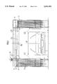
- FIG. 1 is a plan view of a gantry drying apparatus
- FIG. 2 is an end view of the same in the direction II in FIG. 1,
- FIG. 3 is a side view of the same in the direction III in FIG. 1,
- FIG. 4 is a plan view of a second embodiment.
- the invention will be explained in more detail with reference to gantry drying apparatuses for which the arrangement according to the invention is particularly suited.
- the gantry 1 can be driven to and fro horizontally in the longitudinal direction A of the vehicle.
- a cloth drier 2 is arranged on the gantry 1, its main parts being known per se. It comprises an endless conveyor member 3 in a horizontal plane above the path of movement of the vehicle, formed as a conveyor chain as a rule.
- a plurality of yokes 4 are fixed on this conveyor member 3, each serving to receive a strip 5 which hangs down freely.
- This narrow strip 5 can consist wholly or in part of absorbent material. such as textiles, foamed material, leather, leather-like material or even fleece.
- absorbent material such as textiles, foamed material, leather, leather-like material or even fleece.
- each strip has a burr fastener 6 in the region of the yoke 4. It is also possible to provide a further burr fastener in the lower region of the strip 5, so that just the lower part 5a of each strip can be exchanged.
- the endless conveyor member 3 is guided over a guide wheel 7, 8 at each side of the gantry 1, the guide wheel 7 being drivable by the motor 9.
- the guide wheels 7, 8 rotate about vertical axes V.
- the conveyor member 3 has two sections 3a on which no yokes or strips are arranged.
- strip-free sections 3a are referred to as “strip-free" sections.
- the conveyor member 3 In between the two strip-free sections 3a the conveyor member 3 has sections 3b each equipped with strips. The yokes 4 and the strips 5 are therefore only arranged on the sections 3b.
- the length L of the strip-free sections 3a must be greater than the greatest width B of the largest vehicle to be dried with the apparatus. The length L preferably corresponds to the clear width W of the gantry 1.
- a blower device 10 is arranged alongside the conveyor member 3 spaced therefrom in the direction of movement A of the gantry.
- This device consists of a horizontal blower nozzle 11 extending transverse to the longitudinal direction of the vehicle, i.e. transverse to the direction of movement A, and a vertical blower nozzle 12 arranged on each upright 1a of the gantry 1.
- the horizontal blower nozzle 11 can be mounted to be adjustable in height and its height movement can advantageously be controlled by a sensor device 16 sensing the shape of the vehicle acting through a nozzle movement device.
- the vehicle After washing the vehicle by means of a washing gantry, not shown, the vehicle can be dried with the drying apparatus according to the invention.
- the endless conveyor member 3 is stopped in the preceding drying operation as is shown in the drawings.
- the two strip-free sections 3a are located above the through passage region of the gantry, i.e. above the path of relative movement of the vehicle with respect to the gantry.
- two gaps are formed lying one behind the other in the direction of movement A of the gantry 1, i.e. in the direction of relative movement of the vehicle with respect to the gantry, their width corresponding to the length L of the strip-free sections 3a.
- the sections 3b of the conveyor member 3 equipped with strips 5 are located on the two sides of the gantry in the rest position of the conveyor member, in the region of the turn-round locations formed by the guide wheels 7, 8, outside the path of relative movement of the vehicle.
- the strips 5 therefore cannot come into contact with the vehicle in this rest position of the conveyor member 3.
- the gantry is first moved back over the vehicle in the direction A1 from left to right and the greater part of the water on the surface of the vehicle is blown off by the blower nozzles 11, 12. After the gantry has moved back over the whole vehicle, the blower is stopped and the direction of travel of the gantry is reversed.
- the conveyor member 3 is driven in the direction C, D by means of the motor 9.
- the strips 5 are thus moved in the directions C and D during the gantry movement in the direction A2. They are thereby pulled over the surface of the vehicle and thus suck up the residual drops left on the vehicle surface. Since the transverse movement of the strips in the directions C and D is superimposed on the longitudinal movement of the gantry in the direction A2, the strips 5 are pulled diagonally over the surface of the vehicle.
- the motor 9 is so stopped by a suitable limit switch or the like that the two strip-free sections 3a are in the position above the through passage region of the gantry as shown in the drawings, and the sections 3b equipped with strips are arranged on the two sides of the gantry.
- a spray arch 13, 14 consisting of a horizontal part 13 and two vertical parts 14 is arranged on the gantry, in accordance with FIG. 4.
- a movable shield 15 on each side of the gantry 1, which shield can be so swung during operation of the spraying device 13, 14 and in the rest position of the conveyor member 3 that it covers the strips on the inside of the gantry 1 as in FIG. 4.
- Each shield 15 is advantageously pivoted about a vertical axis and can be swung out in the directions E and F respectively by means of a suitable positioning motor, when the cloth drier is to be put into operation.
- the invention can also be used with advantage in washing lines in which the vehicle is drawn through the stationary treatment stations, for example as a polishing apparatus at the end of the washing line.
- the conveyor member 3 is then normally so arranged in the rest position that the strip-free sections 3a are located above the path of movement of the vehicle and the two aforesaid gaps are present in the region of movement of the vehicle.
- the vehicle can then pass the polishing apparatus without the strips being contacted by the vehicle. If however the customer wishes to have his vehicle polished and has paid for this, the conveyor member 3 is set in motion while the vehicle is drawn through the polishing apparatus. The strips are then drawn diagonally over the surface of the vehicle in the manner previously described.
Abstract
Description
Claims (7)
Applications Claiming Priority (2)
| Application Number | Priority Date | Filing Date | Title |
|---|---|---|---|
| DE4402332.4 | 1994-01-27 | ||
| DE4402332A DE4402332C1 (en) | 1994-01-27 | 1994-01-27 | Vehicle drying or polishing device |
Publications (1)
| Publication Number | Publication Date |
|---|---|
| US5555593A true US5555593A (en) | 1996-09-17 |
Family
ID=6508783
Family Applications (1)
| Application Number | Title | Priority Date | Filing Date |
|---|---|---|---|
| US08/359,576 Expired - Lifetime US5555593A (en) | 1994-01-27 | 1994-12-20 | Vehicle drying or polishing apparatus |
Country Status (8)
| Country | Link |
|---|---|
| US (1) | US5555593A (en) |
| EP (1) | EP0665144B1 (en) |
| JP (1) | JPH07223515A (en) |
| AT (1) | ATE148404T1 (en) |
| DE (2) | DE4402332C1 (en) |
| ES (1) | ES2098857T3 (en) |
| FI (1) | FI946130A (en) |
| NO (1) | NO303489B1 (en) |
Cited By (6)
| Publication number | Priority date | Publication date | Assignee | Title |
|---|---|---|---|---|
| US5960564A (en) * | 1998-02-27 | 1999-10-05 | Proto-Vest, Inc. | Side shot two car wash dryer |
| US6147625A (en) * | 1998-11-25 | 2000-11-14 | Wesumat Fahrzeugwaschanlagen Gmbh | Device for positioning motor vehicles in front of a car wash |
| US20060242784A1 (en) * | 2005-04-28 | 2006-11-02 | Wolfgang Decker | Drying gantry for a vehicle wash plant |
| CN100416213C (en) * | 2002-07-04 | 2008-09-03 | Hydac股份有限公司 | Device for heat exchange between flowable media |
| US20170003074A1 (en) * | 2013-12-26 | 2017-01-05 | Beijing Goldwind Science & Creation Windpower Equipment Co., Ltd. | Heating device for annular component and annular cavity thereof |
| FR3113839A1 (en) * | 2020-09-04 | 2022-03-11 | Groupe Larbaletier | DISINFECTION ARCH |
Families Citing this family (2)
| Publication number | Priority date | Publication date | Assignee | Title |
|---|---|---|---|---|
| DE102010016579A1 (en) * | 2010-04-22 | 2011-10-27 | Jürgen Enders | Portal washing plant for cleaning vehicles in service stations, has movable portal, on which cleaning devices for vehicle parked in inner area of portal are arranged |
| DE102021101051A1 (en) | 2021-01-19 | 2022-07-21 | METANK Gesellschaft mit beschränkter Haftung | Vehicle washing installation and method for washing and drying a vehicle |
Citations (6)
| Publication number | Priority date | Publication date | Assignee | Title |
|---|---|---|---|---|
| US1723441A (en) * | 1927-06-20 | 1929-08-06 | John H Richards | Machine for cleaning fruit |
| US4166302A (en) * | 1978-08-31 | 1979-09-04 | Kim Hyun J | Automatic vehicle drying apparatus |
| US4166303A (en) * | 1977-11-11 | 1979-09-04 | Daniel C. Hanna | Dry wiping system for automobiles |
| US4178648A (en) * | 1978-07-28 | 1979-12-18 | Gougoulas Harry K | Dryer curtain for car wash |
| US4949423A (en) * | 1987-06-08 | 1990-08-21 | Sherman Industries, Inc. | Dryer for automatic car wash equipment |
| US4967442A (en) * | 1988-05-26 | 1990-11-06 | Gebhard Weigele | Apparatus for washing or drying vehicles |
Family Cites Families (2)
| Publication number | Priority date | Publication date | Assignee | Title |
|---|---|---|---|---|
| DE3837928C1 (en) * | 1988-11-09 | 1990-02-22 | Gebhard 8902 Neusaess De Weigele | Vehicle washing, polishing or drying device |
| DE4140931C1 (en) * | 1991-12-12 | 1993-04-01 | Wesumat Fahrzeugwaschanlagen Gmbh, 8900 Augsburg, De |
-
1994
- 1994-01-27 DE DE4402332A patent/DE4402332C1/en not_active Expired - Fee Related
- 1994-12-08 EP EP94119375A patent/EP0665144B1/en not_active Expired - Lifetime
- 1994-12-08 AT AT94119375T patent/ATE148404T1/en not_active IP Right Cessation
- 1994-12-08 DE DE59401720T patent/DE59401720D1/en not_active Expired - Lifetime
- 1994-12-08 ES ES94119375T patent/ES2098857T3/en not_active Expired - Lifetime
- 1994-12-14 NO NO944835A patent/NO303489B1/en not_active IP Right Cessation
- 1994-12-20 US US08/359,576 patent/US5555593A/en not_active Expired - Lifetime
- 1994-12-22 JP JP6318962A patent/JPH07223515A/en active Pending
- 1994-12-28 FI FI946130A patent/FI946130A/en unknown
Patent Citations (6)
| Publication number | Priority date | Publication date | Assignee | Title |
|---|---|---|---|---|
| US1723441A (en) * | 1927-06-20 | 1929-08-06 | John H Richards | Machine for cleaning fruit |
| US4166303A (en) * | 1977-11-11 | 1979-09-04 | Daniel C. Hanna | Dry wiping system for automobiles |
| US4178648A (en) * | 1978-07-28 | 1979-12-18 | Gougoulas Harry K | Dryer curtain for car wash |
| US4166302A (en) * | 1978-08-31 | 1979-09-04 | Kim Hyun J | Automatic vehicle drying apparatus |
| US4949423A (en) * | 1987-06-08 | 1990-08-21 | Sherman Industries, Inc. | Dryer for automatic car wash equipment |
| US4967442A (en) * | 1988-05-26 | 1990-11-06 | Gebhard Weigele | Apparatus for washing or drying vehicles |
Non-Patent Citations (2)
| Title |
|---|
| Company brochure WESUMAT softwash washing line system 880811 of the company WESUMAT Fahrzeugwaschanlagen GmbH, D 86156, Augsburg. * |
| Company brochure WESUMAT softwash washing line system 880811 of the company WESUMAT Fahrzeugwaschanlagen GmbH, D-86156, Augsburg. |
Cited By (6)
| Publication number | Priority date | Publication date | Assignee | Title |
|---|---|---|---|---|
| US5960564A (en) * | 1998-02-27 | 1999-10-05 | Proto-Vest, Inc. | Side shot two car wash dryer |
| US6147625A (en) * | 1998-11-25 | 2000-11-14 | Wesumat Fahrzeugwaschanlagen Gmbh | Device for positioning motor vehicles in front of a car wash |
| CN100416213C (en) * | 2002-07-04 | 2008-09-03 | Hydac股份有限公司 | Device for heat exchange between flowable media |
| US20060242784A1 (en) * | 2005-04-28 | 2006-11-02 | Wolfgang Decker | Drying gantry for a vehicle wash plant |
| US20170003074A1 (en) * | 2013-12-26 | 2017-01-05 | Beijing Goldwind Science & Creation Windpower Equipment Co., Ltd. | Heating device for annular component and annular cavity thereof |
| FR3113839A1 (en) * | 2020-09-04 | 2022-03-11 | Groupe Larbaletier | DISINFECTION ARCH |
Also Published As
| Publication number | Publication date |
|---|---|
| NO944835L (en) | 1995-07-28 |
| EP0665144B1 (en) | 1997-01-29 |
| NO303489B1 (en) | 1998-07-20 |
| EP0665144A1 (en) | 1995-08-02 |
| DE4402332C1 (en) | 1995-04-06 |
| JPH07223515A (en) | 1995-08-22 |
| FI946130A (en) | 1995-07-28 |
| ES2098857T3 (en) | 1997-05-01 |
| DE59401720D1 (en) | 1997-03-13 |
| NO944835D0 (en) | 1994-12-14 |
| ATE148404T1 (en) | 1997-02-15 |
| FI946130A0 (en) | 1994-12-28 |
Similar Documents
| Publication | Publication Date | Title |
|---|---|---|
| EP1263537B1 (en) | Cleaning of surfaces | |
| US7806128B2 (en) | No water spill automatic steam car wash system | |
| USRE29516E (en) | Automatic surface polishing system | |
| US4280244A (en) | Dirt collecting floor mat apparatus | |
| US5555593A (en) | Vehicle drying or polishing apparatus | |
| US6679275B2 (en) | Vehicle washing installation | |
| US20080060150A1 (en) | Vehicle wash system including multiple overhead bridges | |
| US3559659A (en) | Vehicle cleaning apparatus | |
| US3729763A (en) | Wheel washing apparatus | |
| US6325863B1 (en) | Method of washing a vehicle | |
| GB1109303A (en) | Cleaning plant for motor vehicles | |
| ITMI981343A1 (en) | EQUIPMENT FOR THE CLEANING OF ROTATING MATS IN SORTING MACHINES AND SORTING MACHINE EQUIPPED WITH THIS APPEARANCE | |
| WO2004062972A2 (en) | Rotary car wash cell | |
| US4957126A (en) | Brush-less washing installation | |
| AU2007296813B2 (en) | Rollover wash unit for a vehicle wash system | |
| CN219257292U (en) | Lens cleaning device and automobile comprising same | |
| CN114938654A (en) | Washing unit, flat surface cleaning machine and method | |
| KR200365508Y1 (en) | control system of auto car washing | |
| GB2224706A (en) | Vehicle washing, polishing or drying apparatus | |
| CN217774890U (en) | Cleaning system for trolley caster | |
| GB2243129A (en) | Vehicle washing apparatus | |
| CA2252709C (en) | Vehicle washing apparatus | |
| GB1291050A (en) | Improvements in and relating to vehicle cleaning apparatus | |
| JP2003335224A (en) | Washing water splash preventing device for car washing machine | |
| CN114985326A (en) | Cleaning system for trolley caster |
Legal Events
| Date | Code | Title | Description |
|---|---|---|---|
| AS | Assignment |
Owner name: WESUMAT FAHRZEUGWASCHANLAGEN GMBH, GERMANY Free format text: ASSIGNMENT OF ASSIGNORS INTEREST;ASSIGNOR:DECKER, WOLFGANG;REEL/FRAME:007298/0945 Effective date: 19941118 |
|
| STCF | Information on status: patent grant |
Free format text: PATENTED CASE |
|
| FEPP | Fee payment procedure |
Free format text: PAT HLDR NO LONGER CLAIMS SMALL ENT STAT AS SMALL BUSINESS (ORIGINAL EVENT CODE: LSM2); ENTITY STATUS OF PATENT OWNER: LARGE ENTITY Free format text: PAYOR NUMBER ASSIGNED (ORIGINAL EVENT CODE: ASPN); ENTITY STATUS OF PATENT OWNER: LARGE ENTITY |
|
| FPAY | Fee payment |
Year of fee payment: 4 |
|
| AS | Assignment |
Owner name: WASHTEC CLEANING TECHNOLOGY GMBH, GERMANY Free format text: NAME CHANGE BY MERGER;ASSIGNOR:WESUMAT FAHRZEUGWASCHANLAGEN GBMH;REEL/FRAME:012263/0198 Effective date: 20001023 |
|
| AS | Assignment |
Owner name: WASHTEC HOLDING GMBH, GERMANY Free format text: ASSIGNMENT OF ASSIGNORS INTEREST;ASSIGNOR:WASHTEC CLEANING TECHNOLOGY GMBH;REEL/FRAME:012263/0601 Effective date: 20010717 |
|
| FPAY | Fee payment |
Year of fee payment: 8 |
|
| FPAY | Fee payment |
Year of fee payment: 12 |