EP4020698A1 - Module de batterie, bloc-batterie comprenant celui-ci, et procédé de fabrication d'un module de batterie - Google Patents
Module de batterie, bloc-batterie comprenant celui-ci, et procédé de fabrication d'un module de batterie Download PDFInfo
- Publication number
- EP4020698A1 EP4020698A1 EP21852694.5A EP21852694A EP4020698A1 EP 4020698 A1 EP4020698 A1 EP 4020698A1 EP 21852694 A EP21852694 A EP 21852694A EP 4020698 A1 EP4020698 A1 EP 4020698A1
- Authority
- EP
- European Patent Office
- Prior art keywords
- electrode lead
- battery cell
- battery
- jig
- overlapping part
- Prior art date
- Legal status (The legal status is an assumption and is not a legal conclusion. Google has not performed a legal analysis and makes no representation as to the accuracy of the status listed.)
- Pending
Links
- 238000004519 manufacturing process Methods 0.000 title claims description 12
- 238000003466 welding Methods 0.000 claims abstract description 46
- 239000011347 resin Substances 0.000 claims description 20
- 229920005989 resin Polymers 0.000 claims description 20
- 238000000034 method Methods 0.000 claims description 19
- 239000000853 adhesive Substances 0.000 claims description 14
- 230000001070 adhesive effect Effects 0.000 claims description 14
- 238000005452 bending Methods 0.000 claims description 13
- 230000008878 coupling Effects 0.000 claims description 4
- 238000010168 coupling process Methods 0.000 claims description 4
- 238000005859 coupling reaction Methods 0.000 claims description 4
- 238000003825 pressing Methods 0.000 claims description 2
- 210000004027 cell Anatomy 0.000 description 139
- 239000010410 layer Substances 0.000 description 19
- 239000000463 material Substances 0.000 description 10
- 238000005192 partition Methods 0.000 description 4
- 230000008901 benefit Effects 0.000 description 3
- 230000007547 defect Effects 0.000 description 3
- 230000000694 effects Effects 0.000 description 3
- 230000004927 fusion Effects 0.000 description 2
- 238000007789 sealing Methods 0.000 description 2
- JOYRKODLDBILNP-UHFFFAOYSA-N Ethyl urethane Chemical compound CCOC(N)=O JOYRKODLDBILNP-UHFFFAOYSA-N 0.000 description 1
- NIXOWILDQLNWCW-UHFFFAOYSA-N acrylic acid group Chemical group C(C=C)(=O)O NIXOWILDQLNWCW-UHFFFAOYSA-N 0.000 description 1
- 239000012790 adhesive layer Substances 0.000 description 1
- 210000005056 cell body Anatomy 0.000 description 1
- 238000001816 cooling Methods 0.000 description 1
- 238000011161 development Methods 0.000 description 1
- 230000005484 gravity Effects 0.000 description 1
- 238000001746 injection moulding Methods 0.000 description 1
- 230000010354 integration Effects 0.000 description 1
- 238000005304 joining Methods 0.000 description 1
- 239000007788 liquid Substances 0.000 description 1
- 239000002184 metal Substances 0.000 description 1
- 238000012986 modification Methods 0.000 description 1
- 230000004048 modification Effects 0.000 description 1
- 230000001151 other effect Effects 0.000 description 1
- 238000013021 overheating Methods 0.000 description 1
- 238000007747 plating Methods 0.000 description 1
- 229920001296 polysiloxane Polymers 0.000 description 1
- 238000011160 research Methods 0.000 description 1
- 239000000243 solution Substances 0.000 description 1
- 239000013589 supplement Substances 0.000 description 1
- 238000012546 transfer Methods 0.000 description 1
Images


Classifications
-
- H—ELECTRICITY
- H01—ELECTRIC ELEMENTS
- H01M—PROCESSES OR MEANS, e.g. BATTERIES, FOR THE DIRECT CONVERSION OF CHEMICAL ENERGY INTO ELECTRICAL ENERGY
- H01M50/00—Constructional details or processes of manufacture of the non-active parts of electrochemical cells other than fuel cells, e.g. hybrid cells
- H01M50/50—Current conducting connections for cells or batteries
- H01M50/531—Electrode connections inside a battery casing
- H01M50/536—Electrode connections inside a battery casing characterised by the method of fixing the leads to the electrodes, e.g. by welding
-
- B—PERFORMING OPERATIONS; TRANSPORTING
- B23—MACHINE TOOLS; METAL-WORKING NOT OTHERWISE PROVIDED FOR
- B23K—SOLDERING OR UNSOLDERING; WELDING; CLADDING OR PLATING BY SOLDERING OR WELDING; CUTTING BY APPLYING HEAT LOCALLY, e.g. FLAME CUTTING; WORKING BY LASER BEAM
- B23K26/00—Working by laser beam, e.g. welding, cutting or boring
- B23K26/20—Bonding
- B23K26/21—Bonding by welding
- B23K26/22—Spot welding
-
- B—PERFORMING OPERATIONS; TRANSPORTING
- B23—MACHINE TOOLS; METAL-WORKING NOT OTHERWISE PROVIDED FOR
- B23K—SOLDERING OR UNSOLDERING; WELDING; CLADDING OR PLATING BY SOLDERING OR WELDING; CUTTING BY APPLYING HEAT LOCALLY, e.g. FLAME CUTTING; WORKING BY LASER BEAM
- B23K26/00—Working by laser beam, e.g. welding, cutting or boring
- B23K26/20—Bonding
- B23K26/21—Bonding by welding
- B23K26/24—Seam welding
- B23K26/244—Overlap seam welding
-
- B—PERFORMING OPERATIONS; TRANSPORTING
- B23—MACHINE TOOLS; METAL-WORKING NOT OTHERWISE PROVIDED FOR
- B23K—SOLDERING OR UNSOLDERING; WELDING; CLADDING OR PLATING BY SOLDERING OR WELDING; CUTTING BY APPLYING HEAT LOCALLY, e.g. FLAME CUTTING; WORKING BY LASER BEAM
- B23K26/00—Working by laser beam, e.g. welding, cutting or boring
- B23K26/20—Bonding
- B23K26/32—Bonding taking account of the properties of the material involved
-
- B—PERFORMING OPERATIONS; TRANSPORTING
- B23—MACHINE TOOLS; METAL-WORKING NOT OTHERWISE PROVIDED FOR
- B23K—SOLDERING OR UNSOLDERING; WELDING; CLADDING OR PLATING BY SOLDERING OR WELDING; CUTTING BY APPLYING HEAT LOCALLY, e.g. FLAME CUTTING; WORKING BY LASER BEAM
- B23K37/00—Auxiliary devices or processes, not specially adapted to a procedure covered by only one of the preceding main groups
- B23K37/04—Auxiliary devices or processes, not specially adapted to a procedure covered by only one of the preceding main groups for holding or positioning work
- B23K37/0426—Fixtures for other work
- B23K37/0435—Clamps
- B23K37/0443—Jigs
-
- H—ELECTRICITY
- H01—ELECTRIC ELEMENTS
- H01M—PROCESSES OR MEANS, e.g. BATTERIES, FOR THE DIRECT CONVERSION OF CHEMICAL ENERGY INTO ELECTRICAL ENERGY
- H01M10/00—Secondary cells; Manufacture thereof
- H01M10/04—Construction or manufacture in general
- H01M10/0468—Compression means for stacks of electrodes and separators
-
- H—ELECTRICITY
- H01—ELECTRIC ELEMENTS
- H01M—PROCESSES OR MEANS, e.g. BATTERIES, FOR THE DIRECT CONVERSION OF CHEMICAL ENERGY INTO ELECTRICAL ENERGY
- H01M10/00—Secondary cells; Manufacture thereof
- H01M10/60—Heating or cooling; Temperature control
- H01M10/64—Heating or cooling; Temperature control characterised by the shape of the cells
- H01M10/647—Prismatic or flat cells, e.g. pouch cells
-
- H—ELECTRICITY
- H01—ELECTRIC ELEMENTS
- H01M—PROCESSES OR MEANS, e.g. BATTERIES, FOR THE DIRECT CONVERSION OF CHEMICAL ENERGY INTO ELECTRICAL ENERGY
- H01M10/00—Secondary cells; Manufacture thereof
- H01M10/60—Heating or cooling; Temperature control
- H01M10/65—Means for temperature control structurally associated with the cells
- H01M10/653—Means for temperature control structurally associated with the cells characterised by electrically insulating or thermally conductive materials
-
- H—ELECTRICITY
- H01—ELECTRIC ELEMENTS
- H01M—PROCESSES OR MEANS, e.g. BATTERIES, FOR THE DIRECT CONVERSION OF CHEMICAL ENERGY INTO ELECTRICAL ENERGY
- H01M50/00—Constructional details or processes of manufacture of the non-active parts of electrochemical cells other than fuel cells, e.g. hybrid cells
- H01M50/10—Primary casings; Jackets or wrappings
- H01M50/147—Lids or covers
- H01M50/148—Lids or covers characterised by their shape
-
- H—ELECTRICITY
- H01—ELECTRIC ELEMENTS
- H01M—PROCESSES OR MEANS, e.g. BATTERIES, FOR THE DIRECT CONVERSION OF CHEMICAL ENERGY INTO ELECTRICAL ENERGY
- H01M50/00—Constructional details or processes of manufacture of the non-active parts of electrochemical cells other than fuel cells, e.g. hybrid cells
- H01M50/10—Primary casings; Jackets or wrappings
- H01M50/172—Arrangements of electric connectors penetrating the casing
- H01M50/174—Arrangements of electric connectors penetrating the casing adapted for the shape of the cells
- H01M50/178—Arrangements of electric connectors penetrating the casing adapted for the shape of the cells for pouch or flexible bag cells
-
- H—ELECTRICITY
- H01—ELECTRIC ELEMENTS
- H01M—PROCESSES OR MEANS, e.g. BATTERIES, FOR THE DIRECT CONVERSION OF CHEMICAL ENERGY INTO ELECTRICAL ENERGY
- H01M50/00—Constructional details or processes of manufacture of the non-active parts of electrochemical cells other than fuel cells, e.g. hybrid cells
- H01M50/20—Mountings; Secondary casings or frames; Racks, modules or packs; Suspension devices; Shock absorbers; Transport or carrying devices; Holders
- H01M50/204—Racks, modules or packs for multiple batteries or multiple cells
- H01M50/207—Racks, modules or packs for multiple batteries or multiple cells characterised by their shape
- H01M50/209—Racks, modules or packs for multiple batteries or multiple cells characterised by their shape adapted for prismatic or rectangular cells
-
- H—ELECTRICITY
- H01—ELECTRIC ELEMENTS
- H01M—PROCESSES OR MEANS, e.g. BATTERIES, FOR THE DIRECT CONVERSION OF CHEMICAL ENERGY INTO ELECTRICAL ENERGY
- H01M50/00—Constructional details or processes of manufacture of the non-active parts of electrochemical cells other than fuel cells, e.g. hybrid cells
- H01M50/20—Mountings; Secondary casings or frames; Racks, modules or packs; Suspension devices; Shock absorbers; Transport or carrying devices; Holders
- H01M50/233—Mountings; Secondary casings or frames; Racks, modules or packs; Suspension devices; Shock absorbers; Transport or carrying devices; Holders characterised by physical properties of casings or racks, e.g. dimensions
- H01M50/242—Mountings; Secondary casings or frames; Racks, modules or packs; Suspension devices; Shock absorbers; Transport or carrying devices; Holders characterised by physical properties of casings or racks, e.g. dimensions adapted for protecting batteries against vibrations, collision impact or swelling
-
- H—ELECTRICITY
- H01—ELECTRIC ELEMENTS
- H01M—PROCESSES OR MEANS, e.g. BATTERIES, FOR THE DIRECT CONVERSION OF CHEMICAL ENERGY INTO ELECTRICAL ENERGY
- H01M50/00—Constructional details or processes of manufacture of the non-active parts of electrochemical cells other than fuel cells, e.g. hybrid cells
- H01M50/20—Mountings; Secondary casings or frames; Racks, modules or packs; Suspension devices; Shock absorbers; Transport or carrying devices; Holders
- H01M50/258—Modular batteries; Casings provided with means for assembling
-
- H—ELECTRICITY
- H01—ELECTRIC ELEMENTS
- H01M—PROCESSES OR MEANS, e.g. BATTERIES, FOR THE DIRECT CONVERSION OF CHEMICAL ENERGY INTO ELECTRICAL ENERGY
- H01M50/00—Constructional details or processes of manufacture of the non-active parts of electrochemical cells other than fuel cells, e.g. hybrid cells
- H01M50/40—Separators; Membranes; Diaphragms; Spacing elements inside cells
- H01M50/471—Spacing elements inside cells other than separators, membranes or diaphragms; Manufacturing processes thereof
- H01M50/474—Spacing elements inside cells other than separators, membranes or diaphragms; Manufacturing processes thereof characterised by their position inside the cells
-
- H—ELECTRICITY
- H01—ELECTRIC ELEMENTS
- H01M—PROCESSES OR MEANS, e.g. BATTERIES, FOR THE DIRECT CONVERSION OF CHEMICAL ENERGY INTO ELECTRICAL ENERGY
- H01M50/00—Constructional details or processes of manufacture of the non-active parts of electrochemical cells other than fuel cells, e.g. hybrid cells
- H01M50/40—Separators; Membranes; Diaphragms; Spacing elements inside cells
- H01M50/489—Separators, membranes, diaphragms or spacing elements inside the cells, characterised by their physical properties, e.g. swelling degree, hydrophilicity or shut down properties
-
- H—ELECTRICITY
- H01—ELECTRIC ELEMENTS
- H01M—PROCESSES OR MEANS, e.g. BATTERIES, FOR THE DIRECT CONVERSION OF CHEMICAL ENERGY INTO ELECTRICAL ENERGY
- H01M50/00—Constructional details or processes of manufacture of the non-active parts of electrochemical cells other than fuel cells, e.g. hybrid cells
- H01M50/50—Current conducting connections for cells or batteries
- H01M50/502—Interconnectors for connecting terminals of adjacent batteries; Interconnectors for connecting cells outside a battery casing
- H01M50/514—Methods for interconnecting adjacent batteries or cells
- H01M50/516—Methods for interconnecting adjacent batteries or cells by welding, soldering or brazing
-
- H—ELECTRICITY
- H01—ELECTRIC ELEMENTS
- H01M—PROCESSES OR MEANS, e.g. BATTERIES, FOR THE DIRECT CONVERSION OF CHEMICAL ENERGY INTO ELECTRICAL ENERGY
- H01M50/00—Constructional details or processes of manufacture of the non-active parts of electrochemical cells other than fuel cells, e.g. hybrid cells
- H01M50/50—Current conducting connections for cells or batteries
- H01M50/528—Fixed electrical connections, i.e. not intended for disconnection
-
- H—ELECTRICITY
- H01—ELECTRIC ELEMENTS
- H01M—PROCESSES OR MEANS, e.g. BATTERIES, FOR THE DIRECT CONVERSION OF CHEMICAL ENERGY INTO ELECTRICAL ENERGY
- H01M50/00—Constructional details or processes of manufacture of the non-active parts of electrochemical cells other than fuel cells, e.g. hybrid cells
- H01M50/50—Current conducting connections for cells or batteries
- H01M50/531—Electrode connections inside a battery casing
- H01M50/533—Electrode connections inside a battery casing characterised by the shape of the leads or tabs
-
- H—ELECTRICITY
- H01—ELECTRIC ELEMENTS
- H01M—PROCESSES OR MEANS, e.g. BATTERIES, FOR THE DIRECT CONVERSION OF CHEMICAL ENERGY INTO ELECTRICAL ENERGY
- H01M50/00—Constructional details or processes of manufacture of the non-active parts of electrochemical cells other than fuel cells, e.g. hybrid cells
- H01M50/50—Current conducting connections for cells or batteries
- H01M50/531—Electrode connections inside a battery casing
- H01M50/54—Connection of several leads or tabs of plate-like electrode stacks, e.g. electrode pole straps or bridges
-
- B—PERFORMING OPERATIONS; TRANSPORTING
- B23—MACHINE TOOLS; METAL-WORKING NOT OTHERWISE PROVIDED FOR
- B23K—SOLDERING OR UNSOLDERING; WELDING; CLADDING OR PLATING BY SOLDERING OR WELDING; CUTTING BY APPLYING HEAT LOCALLY, e.g. FLAME CUTTING; WORKING BY LASER BEAM
- B23K2101/00—Articles made by soldering, welding or cutting
- B23K2101/36—Electric or electronic devices
- B23K2101/38—Conductors
-
- H—ELECTRICITY
- H01—ELECTRIC ELEMENTS
- H01M—PROCESSES OR MEANS, e.g. BATTERIES, FOR THE DIRECT CONVERSION OF CHEMICAL ENERGY INTO ELECTRICAL ENERGY
- H01M2220/00—Batteries for particular applications
- H01M2220/20—Batteries in motive systems, e.g. vehicle, ship, plane
-
- H—ELECTRICITY
- H01—ELECTRIC ELEMENTS
- H01M—PROCESSES OR MEANS, e.g. BATTERIES, FOR THE DIRECT CONVERSION OF CHEMICAL ENERGY INTO ELECTRICAL ENERGY
- H01M50/00—Constructional details or processes of manufacture of the non-active parts of electrochemical cells other than fuel cells, e.g. hybrid cells
- H01M50/20—Mountings; Secondary casings or frames; Racks, modules or packs; Suspension devices; Shock absorbers; Transport or carrying devices; Holders
- H01M50/233—Mountings; Secondary casings or frames; Racks, modules or packs; Suspension devices; Shock absorbers; Transport or carrying devices; Holders characterised by physical properties of casings or racks, e.g. dimensions
- H01M50/24—Mountings; Secondary casings or frames; Racks, modules or packs; Suspension devices; Shock absorbers; Transport or carrying devices; Holders characterised by physical properties of casings or racks, e.g. dimensions adapted for protecting batteries from their environment, e.g. from corrosion
-
- Y—GENERAL TAGGING OF NEW TECHNOLOGICAL DEVELOPMENTS; GENERAL TAGGING OF CROSS-SECTIONAL TECHNOLOGIES SPANNING OVER SEVERAL SECTIONS OF THE IPC; TECHNICAL SUBJECTS COVERED BY FORMER USPC CROSS-REFERENCE ART COLLECTIONS [XRACs] AND DIGESTS
- Y02—TECHNOLOGIES OR APPLICATIONS FOR MITIGATION OR ADAPTATION AGAINST CLIMATE CHANGE
- Y02E—REDUCTION OF GREENHOUSE GAS [GHG] EMISSIONS, RELATED TO ENERGY GENERATION, TRANSMISSION OR DISTRIBUTION
- Y02E60/00—Enabling technologies; Technologies with a potential or indirect contribution to GHG emissions mitigation
- Y02E60/10—Energy storage using batteries
Definitions
- the present disclosure relates to a battery module, a battery pack including the same and a method of manufacturing the battery module, and more particularly, to a battery module manufactured by a novel process, a battery pack including the same and a method of manufacturing the battery module.
- a secondary battery has attracted considerable attention as an energy source for power-driven devices, such as an electric bicycle, an electric vehicle, and a hybrid electric vehicle, as well as an energy source for mobile devices, such as a mobile phone, a digital camera, and a laptop computer.
- Small-sized mobile devices use one or several battery cells for each device, whereas middle or large-sized devices such as vehicles require high power and large capacity. Therefore, a middle or large-sized battery module having a plurality of battery cells electrically connected to one another is used.
- the middle or large-sized battery module is manufactured so as to have as small a size and weight as possible. Consequently, a prismatic battery, a pouch-shaped battery or the like, which can be stacked with high integration and has a small weight relative to capacity, is mainly used as a battery cell of the middle- or large-sized battery module.
- the battery module may include a module frame in which a front surface and back surface are opened to house the battery cell stack in an internal space.
- a plurality of battery cells should be electrically connected in series to each other.
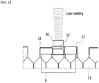
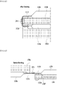
- Fig. 1 is a view for explaining the method of welding an electrode lead in the battery cell stack included in a conventional battery module.
- one or more electrode leads 12 and, 13 bent onto a bus bar 15 can be welded using a jig 30.
- the material of the bus bar 15 is required, and in some cases, plating is required and thus, material costs may increase.
- the space of the P region of Fig. 1 corresponding to the rear face space of the electrode leads 12 and 13 is insufficient, it is difficult to confirm whether the welding surface contact is performed, which makes it difficult to guarantee the welding quality.
- the quality of the bending process can affect the welding quality. Because welding proceeds after stacking the battery cells 11, there is a problem that it is difficult to reuse the battery cell 11 if a defect occurs during welding.
- a battery module comprising: a battery cell stack that is formed by stacking a plurality of battery cells along a first direction; an insulating cover that covers both end parts of the battery cell stack; a holding member that wraps both end parts of the battery cell stack adjacent to the insulating cover; and a first electrode lead and a second electrode lead that protrude from each of a first battery cell and a second battery cell adjacent to each other included in the battery cell stack; wherein the first electrode lead and the second electrode lead are bent in different directions from each other, bent in different directions from each other, and the first electrode lead and the second electrode lead overlap with each other, thereby forming a welding part, and wherein an extra space is formed between the welding part and the battery cell stack.
- One of the first electrode lead and the second electrode lead may be a positive electrode lead, and the other may be a negative electrode lead.
- On overlapping part of the first electrode lead and the second electrode lead on which the welding part is formed may be directly opposite to the battery cell stack.
- a battery pack comprising: the above-mentioned battery module, a pack frame that houses the battery module, and a heat conductive resin layer that is disposed between the battery module and the bottom part of the pack frame.
- a method of manufacturing a battery module comprising the steps of: arranging a first battery cell and a second battery cell in a horizontal direction, and overlapping a first electrode lead protruding from the first battery cell and a second electrode lead protruding from the second battery cell, welding a first overlapping part of the first electrode lead and the second electrode lead, vertically arranging the first battery cell and the second battery cell by bending the first electrode lead and the second electrode lead based on the first overlapping part, and coupling the first battery cell and the second battery cell to each other by an adhesive member.
- the step of bending the first electrode lead and the second electrode lead based on the first overlapping part may be performed using a first jig and a second jig respectively disposed on one surface of the first battery cell and one surface of the second battery cell, and the first jig and the second jig may be disposed on mutually different sides based on the first overlapping part.
- the first jig presses the first electrode lead
- the second jig presses the second electrode lead
- the first jig rotates together with the first battery cell so that the first battery cell and the second battery cell can be vertically arranged.
- the method of manufacturing a battery module may further include disassembling the first jig and the second jig, after the step of vertically arranging the first battery cell and the second battery cell, wherein the first jig and the second jig are disassembled into two equal parts, respectively.
- the method of manufacturing a battery module further includes arranging the second battery cell and the third battery cell in a horizontal direction, and overlapping a third electrode lead protruding from the second battery cell and a fourth electrode lead protruding from the third battery cell, welding a second overlapping part of the third electrode lead and the fourth electrode lead, vertically arranging the second battery cell and the third battery cell by bending the third electrode lead and the fourth electrode lead based on the second overlapping part, and coupling the second battery cell and the third battery cell to each other by an adhesive member, wherein a direction in which the first electrode lead and the second electrode lead are bent and a direction in which the third electrode lead and the fourth electrode lead are bent based on the second overlapping part may form a zigzag structure with each other.
- the second electrode lead and the third electrode lead have different polarities from each other, and the second electrode lead and the third electrode lead may be located at mutually different end parts based on the longitudinal direction of the second battery cell.
- the step of welding the overlapping part may further include pressing both surfaces of the first overlapping part by welding jigs disposed on both surfaces of the first overlapping part.
- the electrode leads are bent using jigs disposed on mutually different sides based on the overlapping part of the electrode leads, thereby increasing the alignment accuracy of the battery cell stack and increasing the space utilization rate.
- planar when referred to as “planar”, it means when a target portion is viewed from the upper side, and when referred to as “cross-sectional”, it means when a target portion is viewed from the side of a cross section cut vertically.
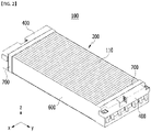
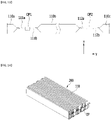
- Fig. 2 is a perspective view illustrating a battery module according to one embodiment of the present disclosure.
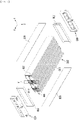
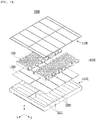
- Fig. 3 is an exploded perspective view of the battery module of Fig. 2 .
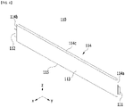
- Fig. 4 is a perspective view of a battery cell included in the battery module of Fig. 2 .
- a battery module 100 includes a battery cell stack 200 in which a plurality of battery cells 110 are stacked.
- the battery cell 110 is preferably a pouch-type battery cell, and may be formed into a rectangular sheet-like structure.
- the battery cell 110 according to the present embodiment has a structure in which two electrode leads 111 and 112 protrude from one end part 114a and the other end part 114b which are disposed on the opposite sides to each other in reference to the cell body 113, respectively. More specifically, the electrode leads 111 and 112 are connected to an electrode assembly (not shown) and protrude from the electrode assembly (not shown) to the outside of the battery cell 110.
- One of the two electrode leads 111 and 112 may be a positive electrode lead 111 and the other may be a negative electrode lead 112. That is, the positive electrode lead 111 and the negative electrode lead 112 can be protruded in opposite directions to each other in reference to one battery cell 110.
- the battery cell 110 can be produced by joining both end parts 114a and 114b of a cell case 114 and one side part 114c connecting them in a state in which an electrode assembly (not shown) is housed in a cell case 114.
- the battery cell 110 according to the present embodiment has a total of three sealing parts, the sealing part has a structure in which it is sealed by a method such as heat fusion, and the remaining other side part may be composed of a connection part 115.
- the cell case 114 may be composed of a laminate sheet including a resin layer and a metal layer.
- Such battery cells 110 may be formed in plural numbers, and the plurality of battery cells 110 are stacked so as to be electrically connected to each other, thereby forming a battery cell stack 200.
- the plurality of battery cells 110 may be stacked along the x-axis direction.
- the electrode leads 111 and 112 can be protruded in the y-axis direction and the -y-axis direction, respectively.
- the battery module 100 according to the present embodiment forms a module-less structure in which the module frame and the end plate are removed.
- the battery module 100 according to the present embodiment may include a side face plate 600 and a holding band 700.
- the module frame and the end plate are removed, complicated processes that require precise control, as in the process of housing the battery cell stack 200 inside the module frame, or the process of assembling module frames and end plates, is not necessary.
- the weight of the battery module 100 can be significantly reduced only by the removed module frame and end plate.
- the battery module 100 according to the present embodiment has an advantage that re-workability is advantageous in the battery pack assembly process due to the removal of the module frame.
- the conventional battery module 10 could not be reworked even if a defect occurs due to the welding structure of the module frame.
- the side face plate 600 is a plate-shaped member and can be disposed on both side surfaces of the battery cell stack 200 to supplement the rigidity of the battery module 100.
- Such side face plate 600 has elastic properties and may include a plastic material manufactured by injection molding, and in some cases, a leaf spring material can be applied.
- a holding band 700 is a member that wraps the battery cell stack 200 at both end parts of the battery cell stack 200, and can has a function of fixing the plurality of battery cells 110 and the side face plates 600 constituting the battery cell stack 200. After the battery cell stack 200 and the side face plate 600 are fixed via the holding band 700 in this way, an insulating cover 400 can be disposed on the front surface and the back surface of the battery cell stack 200 corresponding to the direction in which the electrode leads 111 and 112 protrude. The battery cells 110 and the side face plate 600 included in the battery cell stack 200 are fixed via the holding band 700, whereby the insulating cover 400 can be easily coupled to the front surface and the back surface of the battery cell stack 200.
- Such a holding band 700 can be composed of a material having a predetermined elastic force, and specifically, a structure of a leaf spring can be applied.
- Fig. 5 is a partial cross-sectional view of the region A of Fig. 3 as viewed on the xy plane.
- a first battery cell 110a and a second battery cell 110b adjacent to each other are included in the battery cell stack 200 in which a plurality of battery cells 110 are stacked along the x-axis direction.
- the first electrode lead 111a protrudes from the first battery cell 110a and the second electrode lead 111b protrudes from the second battery cell 110b.
- the first electrode lead 111a and the second electrode lead 111b are bent in different directions from each other, and an end part of the first electrode lead 111a and an end part of the second electrode lead 111b overlap with each other.
- One of the first electrode lead 111a and the second electrode lead 111b may be a positive electrode lead, and the other may be a negative electrode lead.
- an adhesive member 130 may be disposed between the first battery cell 110a and the second battery cell 110b. With such adhesive member 130, the fixing force of the battery cell stack 200, which may become weaker due to the omission of the module frame, can be strengthened.
- an extra space EP is formed between the welding part WP and the battery cell stack 200 according to the present embodiment.
- a structure such as a bus bar frame was disposed between the welding part of the electrode lead and the battery cell stack, and adjacent electrode leads were electrically connected via the bus bar fixed to the bus bar frame by heat fusion or the like.
- a structure such as a bus bar frame can be omitted, a structure can be formed so that the overlapping part of the first and second electrode leads 111a and 111b on which the welding parts WP are formed is directly opposite to the battery cell stack 200.
- the battery module 100 having a more compact configuration can be realized.
- a separate member for connecting the electrode leads, such as a bus bar can be omitted to reduce the material cost.
- Figs. 6 to 14 are views illustrating a method of manufacturing a battery module according to another embodiment of the present disclosure.
- a first battery cell 110a and a second battery cell 110b are arranged in a horizontal direction, and a first electrode lead 111a protruding from the first battery cell 110a and a second electrode lead 111b protruding from the second battery cell 110b are overlapped.
- the first electrode lead 111a and the second electrode lead 111b are adjacent to each other, and an end part of the first electrode lead 111a and an end part of the second electrode lead 111b can overlap to form a first overlapping part OP1.
- Fig. 7 is a view of the figure of Fig. 6 as viewed along the z-axis direction.
- Fig. 8 is a view showing an overlapping part of Fig. 7 .
- the first overlapping part OP1 can be welded.
- the welding jig 140 may be arranged on both sides of the first overlapping part OP1.
- Laser welding can be performed through the opening 140AP formed in the welding jig 140.
- the welding jig 140 can simultaneously press the upper surface of the first electrode lead 111a and the lower surface of the second electrode lead 111b, thereby increasing the welding quality.
- the welding since the welding is performed in a state in which adjacent battery cells are arranged in a horizontal direction, an obstacle does not exist in an upper side space and a lower side space of the first overlapping part OP1, and thus, it can be easily confirmed whether the surface contact of the welding object is well performed.
- the first electrode lead 111a and the second electrode lead 111b may be bent based on the first overlapping part OP1 shown in Fig. 7 .
- the first electrode lead 111a and the second electrode lead 111b are bent in opposite directions to each other.
- the step of bending the first electrode lead 111a and the second electrode lead 111b based on the first overlapping part OP1 is performed using a first jig 150a and a second jig 150b respectively disposed on one surface of the first battery cell 110a and one surface of the second battery cell 110b.
- the first jig 150a and the second jig 150b are disposed on mutually different sides based on the first overlapping part OP1.
- the first jig 150a is disposed on the upper surface of the first battery cell 110a
- the second jig 150b may be disposed on the lower surface of the second battery cell 110b.
- the first jig 150a presses a portion of the first electrode lead 111a located between the first battery cell 110a and the first overlapping part OP1
- the second jig 150b may press a portion of the second electrode lead 111b located between the second battery cell 110b and the first overlapping part OP1.
- the first jig 150a rotates together with the first battery cell 110a so that the second battery cell 110b and the first battery cell 110a are vertically arranged.
- the adhesive member 130 may be formed on the lower surface of the second battery cell 110b before bending the first electrode lead 111a and the second electrode lead 111b.
- an opening 150P is formed so that the first and second battery cells 110a and 110b are inserted into formed in the first and second jigs 150a and 150b, respectively.
- the adhesive member 130 is exposed by the opening 150P of the second jig 150b, and the first battery cell 110a rotates together with the first jig 150a so that one surface of the first battery cell 110a can be coupled to the adhesive member 130. At this time, the first battery cell 110a and the second battery cell 110b can be coupled to each other by the adhesive member 130.
- the second battery cell 110b and the third battery cell 110c are arranged in a horizontal direction, and the third electrode lead 112a protruding from the second battery cell 110b and the fourth electrode lead 112b protruding from the third battery cell 110c can be overlapped with each other. Thereafter, in the same manner as described with reference to Figs. 7 and 8 , the second overlapping part OP2 of the third electrode lead 112a and the fourth electrode lead 112b can be welded.
- the second electrode lead 111b and the third electrode lead 112a have different polarities from each other, and the second electrode lead 111b and the third electrode lead 112a may be located at mutually different end parts based on the longitudinal direction of the second battery cell 110b.
- the third electrode lead 112a and the fourth electrode lead 112b are bent based on the second overlapping part OP2, so that the second battery cell 110b and the third battery cell 110c can be vertically arranged.
- the bending direction of the first electrode lead 111a and the second electrode lead 111b shown in Figs. 9 to 11 and the bending direction of the third electrode lead 112a and the fourth electrode lead 112b are different from each other.
- the first overlapping part OP1 is bent downward based on the second battery cell 110b shown in Fig. 13
- the second overlapping part OP2 is bent upward to form a zigzag structure with each other.
- an adhesive member is formed on the upper surface of the second battery cell 110b or the upper surface of the third battery cell 110c, and when the third battery cell 110c rotates, the second battery cell 110b and the third battery cell 110c can be coupled by an adhesive member located between the second battery cell 110b and the third battery cell 110c.
- the first battery cell 110a, the second battery cell 110b, and the third battery cell 110c are vertically arranged, and a plurality of battery cells 110 may be stacked in a zigzag direction in this manner to form a battery cell stack 200 having a plurality of overlapping part OP as shown in Fig. 14 . Thereafter, an insulating cover can be formed so as to cover both end parts of the battery cell stack 200, thereby manufacturing the battery module 100 shown in Fig. 2 .
- the welding quality is improved by welding the electrode leads before bending, and if a defect occurs during welding, only the corresponding battery cell may be discarded. Therefore, it is possible to prevent the problem of having to dispose of even reusable battery cells from the battery cell stack.
- Fig. 15 is an exploded perspective view illustrating a battery pack according to another embodiment of the present disclosure.
- a battery pack 1000 may include a battery module 100, a pack frame 1100 for housing the battery module 100, and a heat conductive resin layer 1200 located between the battery module 100 and the bottom part 1111 of the pack frame 1100.
- the battery module 100 includes an insulating cover as described above, and instead may form a module-less structure in which the module frame and the end plate are removed.
- a plurality of such battery modules 100 can be housed in the pack frame 1100 to form the battery pack 1000.
- the pack frame 1100 may include a lower pack housing 1110 and an upper pack housing 1120 that covers the lower pack housing 1110, and a plurality of battery modules 100 may be disposed on the bottom part 1111 of the lower pack housing 1110.
- the lower pack housing 1110 has a plurality of module regions, and the plurality of module regions may be partitioned by a plurality of partition walls 1350 formed in the lower pack housing 1110.
- the partition wall 1350 is formed between battery modules 100 adjacent to each other among the plurality of battery modules 100.
- the heat conductive resin layer 1200 includes a first heat conductive resin layer and a second heat conductive resin layer adjacent to each other, the plurality of module regions include a first region and a second region that are partitioned from each other by a partition wall 1350, the first heat conductive resin layer is formed so as to correspond to the first region, and the second heat conductive resin layer may be formed so as to correspond to the second region.
- the first heat conductive resin layer and the second heat conductive resin layer may be disposed separately from each other by the partition wall 1350.
- the heat conductive resin layer 1200 may be formed by applying a heat conductive resin to the bottom part 1111 of the lower pack housing 1110.
- the heat conductive resin may include a heat conductive adhesive material, and specifically, may include at least one of silicone material, urethane material, and acrylic material.
- the heat conductive resin is a liquid during application but is cured after application, so that it can perform the role of fixing the battery module 100 to the lower pack housing 1110. Further, since the heat conductive resin has excellent heat transfer properties, heat generated from the battery cell 100 can be quickly transferred to the bottom part 1111, thereby preventing overheating of the battery pack 1000.
- the lower surface of the battery cell stack 200 of Fig. 3 can be mounted directly on the heat conductive resin layer 1200 applied to the lower pack housing 1110. At this time, the battery cell stack 200 can be fixed to the lower pack housing 1110 by the heat conductive resin layer 1200 having adhesive performance.
- the battery pack 1000 according to the present embodiment can form a heat conductive resin layer capable of fixing the battery module 100, particularly, each battery cell 110 constituting the battery module 100, to the bottom part 1111, thereby improving the structural stability. Further, by eliminating the module frame, the heat generated from the battery cells can be directly transferred from the heat conductive resin layer to the pack frame, thereby improving the cooling efficiency.
- a heat sink structure may be formed on the pack frame.
- the battery module or the battery pack according to embodiments of the present disclosure as described above can be applied to various devices.
- a device may be applied to a vehicle means such as an electric bicycle, an electric vehicle, or a hybrid vehicle, but the present disclosure is not limited thereto, and is applicable to various devices that can use a battery module.
- battery cell 130 adhesive layer 140: welding jig 150a, 150b: first and second jigs 400: insulating cover 700: holding band 1000: battery pack 1100: pack frame
Landscapes
- Chemical & Material Sciences (AREA)
- Chemical Kinetics & Catalysis (AREA)
- Electrochemistry (AREA)
- General Chemical & Material Sciences (AREA)
- Engineering & Computer Science (AREA)
- Physics & Mathematics (AREA)
- Optics & Photonics (AREA)
- Mechanical Engineering (AREA)
- Plasma & Fusion (AREA)
- Manufacturing & Machinery (AREA)
- Battery Mounting, Suspending (AREA)
- Connection Of Batteries Or Terminals (AREA)
Applications Claiming Priority (2)
| Application Number | Priority Date | Filing Date | Title |
|---|---|---|---|
| KR1020200097868A KR20220017643A (ko) | 2020-08-05 | 2020-08-05 | 전지 모듈, 이를 포함하는 전지 팩 및 전지 모듈 제조 방법 |
| PCT/KR2021/008914 WO2022030785A1 (fr) | 2020-08-05 | 2021-07-12 | Module de batterie, bloc-batterie comprenant celui-ci, et procédé de fabrication d'un module de batterie |
Publications (2)
| Publication Number | Publication Date |
|---|---|
| EP4020698A1 true EP4020698A1 (fr) | 2022-06-29 |
| EP4020698A4 EP4020698A4 (fr) | 2024-01-24 |
Family
ID=80117333
Family Applications (1)
| Application Number | Title | Priority Date | Filing Date |
|---|---|---|---|
| EP21852694.5A Pending EP4020698A4 (fr) | 2020-08-05 | 2021-07-12 | Module de batterie, bloc-batterie comprenant celui-ci, et procédé de fabrication d'un module de batterie |
Country Status (6)
| Country | Link |
|---|---|
| US (1) | US20240072389A1 (fr) |
| EP (1) | EP4020698A4 (fr) |
| JP (1) | JP7394975B2 (fr) |
| KR (1) | KR20220017643A (fr) |
| CN (1) | CN114467224A (fr) |
| WO (1) | WO2022030785A1 (fr) |
Families Citing this family (1)
| Publication number | Priority date | Publication date | Assignee | Title |
|---|---|---|---|---|
| DE102022116295A1 (de) | 2022-06-30 | 2024-01-04 | Webasto SE | Verfahren zum Herstellen eines Batteriemoduls und Batteriemodul |
Family Cites Families (10)
| Publication number | Priority date | Publication date | Assignee | Title |
|---|---|---|---|---|
| US20100248010A1 (en) | 2009-01-12 | 2010-09-30 | A123 Systems, Inc. | Bi-metallic busbar jumpers for battery systems |
| JP5897121B2 (ja) | 2011-07-25 | 2016-03-30 | エルジー・ケム・リミテッド | 信頼性の向上した電池モジュール及びこれを備えた中大型電池パック |
| WO2014128841A1 (fr) | 2013-02-20 | 2014-08-28 | 株式会社 日立製作所 | Batterie assemblée et batterie utilisée dans celle-ci |
| KR101747397B1 (ko) * | 2013-09-25 | 2017-06-14 | 주식회사 엘지화학 | 댐핑 구조가 형성되어 있는 전극리드를 포함하는 전지모듈 |
| WO2016004079A1 (fr) | 2014-06-30 | 2016-01-07 | Black & Decker Inc. | Bloc-batterie pour des outils électriques sans fil |
| KR102082384B1 (ko) * | 2015-08-11 | 2020-02-27 | 주식회사 엘지화학 | 금속 팩 케이스와 열전도 부재를 포함하는 전지팩 |
| KR102056875B1 (ko) * | 2015-11-10 | 2019-12-17 | 주식회사 엘지화학 | 배터리 모듈 및 이를 포함하는 배터리 팩 |
| KR101858680B1 (ko) * | 2016-08-11 | 2018-05-16 | (주)테크랜드 | 2차 전지용 셀의 폴딩 장치 및 방법 |
| JP6789858B2 (ja) | 2017-03-13 | 2020-11-25 | 株式会社エンビジョンAescエナジーデバイス | 組電池の製造方法及び製造装置 |
| KR102452328B1 (ko) * | 2019-01-10 | 2022-10-11 | 주식회사 엘지에너지솔루션 | 이차전지 및 그 제조방법 |
-
2020
- 2020-08-05 KR KR1020200097868A patent/KR20220017643A/ko active Search and Examination
-
2021
- 2021-07-12 WO PCT/KR2021/008914 patent/WO2022030785A1/fr active Application Filing
- 2021-07-12 EP EP21852694.5A patent/EP4020698A4/fr active Pending
- 2021-07-12 US US17/766,858 patent/US20240072389A1/en active Pending
- 2021-07-12 CN CN202180005487.0A patent/CN114467224A/zh active Pending
- 2021-07-12 JP JP2022519540A patent/JP7394975B2/ja active Active
Also Published As
| Publication number | Publication date |
|---|---|
| CN114467224A (zh) | 2022-05-10 |
| EP4020698A4 (fr) | 2024-01-24 |
| JP2022549925A (ja) | 2022-11-29 |
| WO2022030785A1 (fr) | 2022-02-10 |
| KR20220017643A (ko) | 2022-02-14 |
| JP7394975B2 (ja) | 2023-12-08 |
| US20240072389A1 (en) | 2024-02-29 |
Similar Documents
| Publication | Publication Date | Title |
|---|---|---|
| CN113795972B (zh) | 电池模块和包括该电池模块的电池组 | |
| EP4020668A1 (fr) | Bloc-batterie et dispositif le comprenant | |
| CN113795971B (zh) | 电池模块、其制造方法及电池组 | |
| CN113692672B (zh) | 电池模块、制造该电池模块的方法以及电池组 | |
| EP4044352A1 (fr) | Module de batterie, bloc-batterie le comprenant et procédé de fabrication de bloc-batterie | |
| CN113812035B (zh) | 电池模块、其制造方法以及电池组 | |
| CN113711433A (zh) | 电池模块和包括该电池模块的电池组 | |
| KR102465865B1 (ko) | 전지 모듈, 이의 제조 방법 및 전지팩 | |
| CN113748564B (zh) | 电池模块以及包括该电池模块的电池组 | |
| CN113812036B (zh) | 电池模块和包括该电池模块的电池组 | |
| EP4020698A1 (fr) | Module de batterie, bloc-batterie comprenant celui-ci, et procédé de fabrication d'un module de batterie | |
| EP4024568A1 (fr) | Bloc-batterie et son procédé de fabrication | |
| CN114651364B (zh) | 电池模块和包括该电池模块的电池组 | |
| EP4057431A1 (fr) | Module de batterie et empilement de batterie le comprenant | |
| EP4037080A1 (fr) | Module de batterie et son procédé de fabrication | |
| EP4020687A1 (fr) | Module de batterie, bloc-batterie le comprenant et procédé de transport de module de batterie | |
| EP3968445A2 (fr) | Dispositif de fabrication de module de batterie et procédé de fabrication de module de batterie |
Legal Events
| Date | Code | Title | Description |
|---|---|---|---|
| STAA | Information on the status of an ep patent application or granted ep patent |
Free format text: STATUS: THE INTERNATIONAL PUBLICATION HAS BEEN MADE |
|
| PUAI | Public reference made under article 153(3) epc to a published international application that has entered the european phase |
Free format text: ORIGINAL CODE: 0009012 |
|
| STAA | Information on the status of an ep patent application or granted ep patent |
Free format text: STATUS: REQUEST FOR EXAMINATION WAS MADE |
|
| 17P | Request for examination filed |
Effective date: 20220323 |
|
| AK | Designated contracting states |
Kind code of ref document: A1 Designated state(s): AL AT BE BG CH CY CZ DE DK EE ES FI FR GB GR HR HU IE IS IT LI LT LU LV MC MK MT NL NO PL PT RO RS SE SI SK SM TR |
|
| DAV | Request for validation of the european patent (deleted) | ||
| DAX | Request for extension of the european patent (deleted) | ||
| A4 | Supplementary search report drawn up and despatched |
Effective date: 20240102 |
|
| RIC1 | Information provided on ipc code assigned before grant |
Ipc: H01M 50/516 20210101ALI20231219BHEP Ipc: H01M 50/209 20210101ALI20231219BHEP Ipc: H01M 50/178 20210101ALI20231219BHEP Ipc: B23K 37/04 20060101ALI20231219BHEP Ipc: B23K 26/32 20140101ALI20231219BHEP Ipc: B23K 26/244 20140101ALI20231219BHEP Ipc: B23K 26/22 20060101ALI20231219BHEP Ipc: H01M 50/489 20210101ALI20231219BHEP Ipc: H01M 50/474 20210101ALI20231219BHEP Ipc: B23K 101/38 20060101ALI20231219BHEP Ipc: B23K 26/21 20140101ALI20231219BHEP Ipc: H01M 10/647 20140101ALI20231219BHEP Ipc: H01M 10/653 20140101ALI20231219BHEP Ipc: H01M 50/24 20210101ALI20231219BHEP Ipc: H01M 50/20 20210101ALI20231219BHEP Ipc: H01M 50/502 20210101AFI20231219BHEP |