EP4019997B1 - Verfahren zur steuerung der lichtemission von lichtstäben mit uwb-positionierung - Google Patents
Verfahren zur steuerung der lichtemission von lichtstäben mit uwb-positionierung Download PDFInfo
- Publication number
- EP4019997B1 EP4019997B1 EP20870378.5A EP20870378A EP4019997B1 EP 4019997 B1 EP4019997 B1 EP 4019997B1 EP 20870378 A EP20870378 A EP 20870378A EP 4019997 B1 EP4019997 B1 EP 4019997B1
- Authority
- EP
- European Patent Office
- Prior art keywords
- cheering
- sticks
- base stations
- location
- location base
- Prior art date
- Legal status (The legal status is an assumption and is not a legal conclusion. Google has not performed a legal analysis and makes no representation as to the accuracy of the status listed.)
- Active
Links
Images



Classifications
-
- G—PHYSICS
- G01—MEASURING; TESTING
- G01S—RADIO DIRECTION-FINDING; RADIO NAVIGATION; DETERMINING DISTANCE OR VELOCITY BY USE OF RADIO WAVES; LOCATING OR PRESENCE-DETECTING BY USE OF THE REFLECTION OR RERADIATION OF RADIO WAVES; ANALOGOUS ARRANGEMENTS USING OTHER WAVES
- G01S5/00—Position-fixing by co-ordinating two or more direction or position line determinations; Position-fixing by co-ordinating two or more distance determinations
- G01S5/02—Position-fixing by co-ordinating two or more direction or position line determinations; Position-fixing by co-ordinating two or more distance determinations using radio waves
- G01S5/10—Position of receiver fixed by co-ordinating a plurality of position lines defined by path-difference measurements, e.g. omega or decca systems
-
- H—ELECTRICITY
- H05—ELECTRIC TECHNIQUES NOT OTHERWISE PROVIDED FOR
- H05B—ELECTRIC HEATING; ELECTRIC LIGHT SOURCES NOT OTHERWISE PROVIDED FOR; CIRCUIT ARRANGEMENTS FOR ELECTRIC LIGHT SOURCES, IN GENERAL
- H05B47/00—Circuit arrangements for operating light sources in general, i.e. where the type of light source is not relevant
- H05B47/10—Controlling the light source
- H05B47/175—Controlling the light source by remote control
- H05B47/19—Controlling the light source by remote control via wireless transmission
-
- G—PHYSICS
- G01—MEASURING; TESTING
- G01S—RADIO DIRECTION-FINDING; RADIO NAVIGATION; DETERMINING DISTANCE OR VELOCITY BY USE OF RADIO WAVES; LOCATING OR PRESENCE-DETECTING BY USE OF THE REFLECTION OR RERADIATION OF RADIO WAVES; ANALOGOUS ARRANGEMENTS USING OTHER WAVES
- G01S1/00—Beacons or beacon systems transmitting signals having a characteristic or characteristics capable of being detected by non-directional receivers and defining directions, positions, or position lines fixed relatively to the beacon transmitters; Receivers co-operating therewith
- G01S1/02—Beacons or beacon systems transmitting signals having a characteristic or characteristics capable of being detected by non-directional receivers and defining directions, positions, or position lines fixed relatively to the beacon transmitters; Receivers co-operating therewith using radio waves
- G01S1/04—Details
- G01S1/042—Transmitters
-
- G—PHYSICS
- G01—MEASURING; TESTING
- G01S—RADIO DIRECTION-FINDING; RADIO NAVIGATION; DETERMINING DISTANCE OR VELOCITY BY USE OF RADIO WAVES; LOCATING OR PRESENCE-DETECTING BY USE OF THE REFLECTION OR RERADIATION OF RADIO WAVES; ANALOGOUS ARRANGEMENTS USING OTHER WAVES
- G01S5/00—Position-fixing by co-ordinating two or more direction or position line determinations; Position-fixing by co-ordinating two or more distance determinations
- G01S5/02—Position-fixing by co-ordinating two or more direction or position line determinations; Position-fixing by co-ordinating two or more distance determinations using radio waves
- G01S5/0205—Details
- G01S5/0236—Assistance data, e.g. base station almanac
-
- H—ELECTRICITY
- H04—ELECTRIC COMMUNICATION TECHNIQUE
- H04W—WIRELESS COMMUNICATION NETWORKS
- H04W4/00—Services specially adapted for wireless communication networks; Facilities therefor
- H04W4/02—Services making use of location information
-
- H—ELECTRICITY
- H04—ELECTRIC COMMUNICATION TECHNIQUE
- H04W—WIRELESS COMMUNICATION NETWORKS
- H04W4/00—Services specially adapted for wireless communication networks; Facilities therefor
- H04W4/02—Services making use of location information
- H04W4/023—Services making use of location information using mutual or relative location information between multiple location based services [LBS] targets or of distance thresholds
-
- H—ELECTRICITY
- H05—ELECTRIC TECHNIQUES NOT OTHERWISE PROVIDED FOR
- H05B—ELECTRIC HEATING; ELECTRIC LIGHT SOURCES NOT OTHERWISE PROVIDED FOR; CIRCUIT ARRANGEMENTS FOR ELECTRIC LIGHT SOURCES, IN GENERAL
- H05B47/00—Circuit arrangements for operating light sources in general, i.e. where the type of light source is not relevant
- H05B47/10—Controlling the light source
- H05B47/155—Coordinated control of two or more light sources
-
- H—ELECTRICITY
- H05—ELECTRIC TECHNIQUES NOT OTHERWISE PROVIDED FOR
- H05B—ELECTRIC HEATING; ELECTRIC LIGHT SOURCES NOT OTHERWISE PROVIDED FOR; CIRCUIT ARRANGEMENTS FOR ELECTRIC LIGHT SOURCES, IN GENERAL
- H05B47/00—Circuit arrangements for operating light sources in general, i.e. where the type of light source is not relevant
- H05B47/10—Controlling the light source
- H05B47/16—Controlling the light source by timing means
-
- G—PHYSICS
- G01—MEASURING; TESTING
- G01S—RADIO DIRECTION-FINDING; RADIO NAVIGATION; DETERMINING DISTANCE OR VELOCITY BY USE OF RADIO WAVES; LOCATING OR PRESENCE-DETECTING BY USE OF THE REFLECTION OR RERADIATION OF RADIO WAVES; ANALOGOUS ARRANGEMENTS USING OTHER WAVES
- G01S2201/00—Indexing scheme relating to beacons or beacon systems transmitting signals capable of being detected by non-directional receivers and defining directions, positions, or position lines fixed relatively to the beacon transmitters
- G01S2201/01—Indexing scheme relating to beacons or beacon systems transmitting signals capable of being detected by non-directional receivers and defining directions, positions, or position lines fixed relatively to the beacon transmitters adapted for specific applications or environments
-
- G—PHYSICS
- G01—MEASURING; TESTING
- G01S—RADIO DIRECTION-FINDING; RADIO NAVIGATION; DETERMINING DISTANCE OR VELOCITY BY USE OF RADIO WAVES; LOCATING OR PRESENCE-DETECTING BY USE OF THE REFLECTION OR RERADIATION OF RADIO WAVES; ANALOGOUS ARRANGEMENTS USING OTHER WAVES
- G01S2205/00—Position-fixing by co-ordinating two or more direction or position line determinations; Position-fixing by co-ordinating two or more distance determinations
- G01S2205/01—Position-fixing by co-ordinating two or more direction or position line determinations; Position-fixing by co-ordinating two or more distance determinations specially adapted for specific applications
Definitions
- the invention relates to the technical field of communication, in particular to a method for controlling cheering sticks to emit light based on a UWB location technology.
- light sticks also referred to as cheering sticks
- the audience can wave their cheering sticks to cheer for the teams they like, or shout for the singers they like, so as to promote the atmosphere of the whole concert or match.
- existing cheering sticks have the following defects: first, the cheering sticks can only emit light in one color; and second, the cheering sticks of the audience are independent and cannot be combined to fulfill an overall effect.
- EP 3360201A0 / WO 2017062902A1 disclosed a systems and methods for determining user equipment (UE) locations within a wireless network using reference signals of the wireless network.
- KR 101939627B1 disclosed an audience seat performance directing method for a concert hall using a plurality of light emitting devices for cheering.
- US 20190147711A1 disclosed a method of displaying an image at a venue.
- WO 2014096861A2 / WO 2014096861A3 disclosed methods and apparatus for forming an image using plural pixel devices.
- the objective of the invention is to overcome the defects of the prior art by providing a method for controlling cheering sticks to emit light based on a UWB location technology, which controls the cheering sticks to emit specific light in different sequences through a control center, so to combine the light emitted by the cheering sticks in a whole area into a specific image to fulfill a large-scale display effect or an animation playing effect, thus further igniting the atmosphere of a whole scene.
- the invention is set forth in the independent claims. Additional aspects of the invention are set forth in the dependent claims.
- the invention has the following beneficial effects: according to the method for controlling cheering sticks to emit light based on a UWB location technology, location base stations are set first to generate a wireless local area network to cover a target area; then, after cheering sticks are connected to the location base stations through the wireless local area network, position coordinates of the cheering sticks are obtained according to signals sent by the location base stations, and the position coordinates are converted into display coordinates according to a stadium seat mapping table; and finally, the cheering sticks acquire animation data from the location base stations, a play sequence of the cheering sticks is calculated according to the animation data and the display coordinates, and the cheering sticks are played synchronously to realize animation play of a cheering stick array.
- the invention controls the cheering sticks to emit light according to the play sequence, so that the light emitted by the cheering sticks in a whole area forms a specific image to realize a large-scale display effect or an animation play effect, thus further igniting the atmosphere of the whole scene.
- Seats where fans sit do not need to be classified or numbered in advance.
- Light sticks are linear sticks capable of emitting light in dark, and have been widely applied in many scenarios such as night fishing, wedding celebrations, outdoor activities, concerts and matches.
- Traditional light sticks emit light based on the following principle: a peroxide and an ester compound are contained in an interlayer of the light sticks and react with each other, after glass is broken by bending, hitting or twisting, to enable a fluorochrome to emit light.
- chemluminescent light sticks are disposable and cannot be used repeatedly.
- light sticks using light beads to emit light are developed and can be used repeatedly after being charged.
- Such light sticks (cheering sticks) typically comprise several light-emitting diodes, a battery, a circuit board, and an on-off switch, are generally in a bar shape or other shapes, and can only be turned on or off.
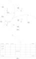
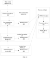
- a method for controlling cheering sticks 23 to emit light based on a UWB location technology comprises the following steps:
- a stadium where a match or a concert is held is surveyed and mapped to obtain the sizes of the stadium and position information of an auditorium 12, a stage 11 and the location base stations 21 in the stadium.
- a position coordinate system is established with a corner of the stadium as the origin of the coordinate system; then, coordinate values of seats in the auditorium 12 in the position coordinate system are obtained; and coordinate values of the local base stations 21 in an absolute base station are measured to obtain a stadium seat mapping table, and the stadium seat mapping table is stored in main control equipment 22 after being made.
- the wireless local area network generated by the base stations should be able to completely cover the stadium, so that any point covered by the wireless local area network can be located by the base stations; after the base stations are set, the cheering sticks 23 (light sticks) are given to audience when the audience enter the stadium, and the audience may sit at any position in the stadium; the base stations are able to locate any cheering stick 23, and seats where the fans sit do not need to be classified or numbered in advance; and after all the audience have a seat, the positions of the cheering sticks 23, held by the audience, in a whole cheering stick 23 array are calculated according to the location base stations 21; and finally, the cheering sticks 23 emit light regularly according to received animation data, so that an animation is played by the whole auditorium 12 like a display screen.
- the cheering sticks 23 are located through a UWB (Ultra Wide Band) location technology, which is a carrier-free communication technology that transmits data by means of nanosecond-level non-sinusoidal narrow pulses, thus having a wide spectral range.
- UWB location adopts the wide-band pulse communication technology and has an extremely high anti-interference capacity, thus reducing location errors.
- the UWB indoor location technology fills in a blank in the field of high-accuracy location, and has the advantages of being insensitive to channel fading, low in power spectral density of transmitted signals, low in interception capacity, low in system complicity, and capable of providing centimeter-level location accuracy.
- the cheering sticks 23 are provided with UWB location tags, and the UWB location tags are active tags that may be fixed on objects or vehicles or worn by people in different forms, and are variable in different application scenarios.
- the active tags are fixed on the cheering sticks 23, and the location accuracy of the active tags may reach 5-10cm; each active tag has a unique ID which is bound with one cheering stick 23, and after the tag receives signals sent by the location base stations, display coordinates of the cheering stick 23 with this ID are obtained by calculation; and the signal sent by the same base station may be synchronously received by tens of thousands of cheering sticks 23.
- the cheering sticks When the position coordinates of the cheering sticks are acquired in S2, the cheering sticks receive location beacons sent by the location base stations first, and then the position coordinates of the cheering sticks are calculated through a TDOA algorithm.
- the distances from the active tags to the location base stations 21 can be determined by the location base stations 21 through a TDOA measurement technology, and the location accuracy reaches the centimeter level. Due to the fact that the width of the seats in the auditorium 12 is about 45-55cm, that is, the distance between the adjacent cheering sticks 23 is about 50cm, the cheering sticks 23 will not be located to adjacent seats, and completely accurate location is guaranteed.
- At least four location base stations are used for TDOA location, namely hyperbolic location.
- a difference between the distances from each tag to every two base stations is measured, a hyperbola is drawn according to the difference which is a constant, and the coordinates of the tag are determined according to an intersection point of all the hyperbolae.
- the cheering sticks receive a stadium seat mapping table sent by the location base stations first, wherein the stadium seat mapping table comprises position coordinates of all the seats in the stadium and has a one-to-one corresponding relationship with the display coordinates; and the position coordinates of the cheering sticks are calculated first, and then, the display coordinates of the cheering sticks are calculated according to the stadium seat mapping table.
- a difference between the distances from each cheering stick to every two base stations is obtained according to a difference between the times when the cheering stick 23 receives the location beacons from these two base stations, a hyperbola is drawn according to the difference between the distances, and an intersection point of all hyperbolas is a unique position of the cheering stick 23; wherein, before the location base stations send the location beacons, the times of the base stations are synchronous.
- the UWB location technology is a mature location technology, so the principle of the UWB location technology is briefly introduced here.
- a difference d1 between the time when the cheering stick 23 with an ID a1 receives a location beacon sent by a first base station and the time when the cheering stick 23 with the ID a1 receives a location beacon sent by a second base station a difference d1 between the distance from this cheering stick to the first base station and the distance from this cheering stick to the second base station is obtained, and a first hyperbola with the first base station as a first focal point and the second base station as a second focal point is obtained using d1 as a distance difference;
- a difference d2 between the distance from this cheering stick 23 to the first base station and the distance from this cheering stick 23 to a third base station is obtained according to a difference t2 between the time when this cheering stick 23 receives the location beacon sent by the first base station and the time when this cheering stick 23 receives a location beacon sent by the third base station, and a second hyperbola with the first base station as the first focal point and the third base station as a second focal point
- the position coordinate system is established with a corner or a special point in the stadium map, which is drawn in advance, as the origin of coordinates, the coordinates of the location base stations 21 in the position coordinate system are fixed, and the coordinates (x1, y1) of the cheering stick 23 with the ID a1 in the position coordinate system are obtained after the unique positions of the cheering stick 23 with respect to the location base stations 21 are determined.
- the position coordinates are calculated by a device inside the cheering stick 23.
- a stadium seat mapping table sent by the location base stations is received first, wherein the stadium seat mapping table comprises position coordinates and a display coordinate mapping table; and the position coordinates of the cheering sticks are converted into the corresponding display coordinates according to the mapping table.
- the position coordinates of all seats have been drawn in the mapping table in advance and are combined to form an array, and each seat corresponds to one cheering stick 23 at most after audience have their seat, so the array of the seats is the cheering stick 23 array.
- the cheering sticks 23ID corresponding to the seats with the position coordinates (x1, y1), (x2, y2), ..., and (xn, yn) are respectively a1, a2, ..., and an. That is to say, the positions of the cheering sticks with IDs a1, a2, ..., and an in the cheering stick 23 array are determined after being measured by the location base stations 21.
- relative coordinates of the cheering sticks 23 with IDs a1, a2, ..., and an can be obtained according to the position coordinates and a display coordinate mapping table.
- the display coordinates of the cheering stick 23 with the position coordinates (x1, y1) are (It*, Jt*), and the ID of the cheering stick 23 with the position coordinates (x1, y1) is at, so it can be figured out that the display coordinates of the cheering stick with the ID at are (It*, Jt*), and the display coordinates indicate the position of the cheering stick 23 in the whole cheering stick 23 array.
- the display coordinates indicate the position of the cheering stick 23 with the ID at, as a pixel, in the display screen.
- the IDs the cheering sticks on all the seats can be obtained according to the display coordinates of all the cheering sticks 23.
- the cheering sticks 23 After the IDs of the cheering sticks 23 on all the seats are obtained, the cheering sticks 23 acquire animation data from the location base stations 21 and generate play sequences according to the display coordinates. Wherein, the play sequences of the cheering sticks are figured out from the animation data according to the display coordinates of the cheering sticks and are one-dimensional data varying with time. The light-emitting state of the cheering sticks 23 is controlled according to the play sequences, like the pixels emitting light in a rule on the display screen, so that an overall animation play effect is fulfilled.
- the cheering sticks receive play time signals sent by the location base stations before emitting light in order, and the play time signals are used to control the cheering sticks to start to emit light at a specific time.
- the play time refers to the play time of specific animation data included in information sent by the base stations, and at this time, all the cheering sticks synchronously play their play sequences figured out from the same animation data. That is, all the cheering sticks start to emit light at the same time according to a check signal.
- the cheering sticks 23 for providing a background color just need to emit white light all the time, and the cheering sticks for forming the words need to emit red light for one second and then emit blue light for one second.
- the display coordinates of the cheering sticks 23 for providing the background color are (Iw1*, Jw1*), (Iw2*, Jw2*), ..., and (Iwn*, Jwn*), the IDs of the corresponding cheering sticks 23 are aw1, aw2, ..., and awn respectively, the display coordinates of the cheering sticks 23 for forming the words are (Ir1*, Jr1*), (Ir2*, Jr2*), ..., and (Im*, Jrn*), the IDs of the corresponding cheering sticks 23 are ar1, ar2, ..., and arw respectively, cheering sticks 23 with the IDs aw1, aw2, ..., and awn emit white light all the time, and the cheering sticks with the IDs ar1, ar2, ..., and arw emit red light for one second and then emit blue light for one second, so that the animation data " " is played.
- the invention further provides a method for controlling cheering sticks 23 to emit light based on a UWB location technology, comprising:
- the number of the base stations is at least four.
- At least one of the location base stations 21 is a main location base station 211 which is in a communication connection with main control equipment 22, and the other location base stations 21 are all in a communication connection with main location base station 211.
- the main location base station 211 receives animation data transmitted from the main control equipment 22, such as a piece of animation data "XXX team will prevail"; after the animation data is transmitted from the main control equipment 22 to the main location base station 211, the main location base station 211 sends the animation data to the other base stations through a broadcast channel, and then the location base stations 21 transmit the animation data to the cheering sticks 23.
- the cheering sticks 23 can receive signals sent by multiple location base stations 21, the base stations send animation data to the cheering sticks 23 respectively and sequentially; the animation data sent by each base station has an identification number; and when the cheering sticks 23 receive the animation data sent by any one base station, this cheering sticks 23 will no longer receive animation data sent by other base stations.
- the main control equipment 22 is connected to the main location base station 211 in a wired manner or a wireless manner, and the base stations communicate with each other; before the location base stations 21 send the animation data to the cheering sticks 23, and the main location base station 211 receives animation data transmitted from the main control equipment 22 first and then transmits the animation data to the other location base stations 21.
- the main location base station 211 transmits the animation data to a location base station 21 in direct communication with the main location base station 211, then the location base station 21 connected to the main location base station 211 transmits the animation data to other location base stations 21 connected thereto, and then the location base stations 21 transmit the animation data to the cheering sticks 23 in sequence.
- the location base stations after sending the animation data to the cheering sticks, also send play time signals to the cheering sticks to control all the cheering sticks to emit light at the same time. In this way, it is ensured that all the cheering sticks emit light at the same time according to play sequences to fulfill an overall display effect. If the cheering sticks start to emit light at different times, the display effect will be disordered even if the cheering sticks emit light according to the play sequences.
- a system for controlling cheering sticks 23 to emit light based on a UWB technology comprising:
- each location base station 21 comprises a first transmission device 212.
- At least one of the location base stations 21 is a main location base station 211, which comprises a first receiving device 214 and is in a communication connection with main control equipment 22 through the first receiving device 214.
- the other location base stations are in communication with the main location base station 211 through the first transmission devices 212.
- each cheering stick 23 further comprises a location tag.
- the UWB device 231 receives location beacons fed back by the base stations to obtain differences between the distances from the cheering stick 23 to the location base stations 21, and the processing devices 232 obtain fixed values of the position coordinates according to the differences between the distances from the cheering stick 23 and the location base stations 21.
- the UWB devices when the processing devices 23 convert the position coordinates into the display coordinates in the cheering stick array formed by the cheering sticks, the UWB devices receive a stadium seat mapping table sent by the location base stations first, wherein the position coordinates of the cheering sticks are converted into the display coordinates according to the stadium seat mapping table.
- the processing devices 232 After the UWB devices 231 acquire the animation data from the location base stations 21, the processing devices 232 generate play sequences according to the display coordinates of the cheering sticks and the animation data, and the display devices 233 emits light according to the play sequences.
- Each display device 233 comprises red, green and blue light beads for emitting light, and a control device for controlling a light emitting ratio of the light beads. Light in any color can be obtained by controlling the ratio of the red, green and blue light beads.
- the display devices 233 control the light emitting color and the light emitting time according to the play sequences.
- the invention further provides a system for controlling cheering sticks 23 to emit light based on a UWB location technology, comprising:
- At least four location base stations 21 are set. Each location base station 21 comprises a first transmission device. At least one of the location base stations 21 is a main location base station 211, which comprises a first receiving device 214 and is in a communication connection with main control equipment 22 through the first receiving device 214. The other location base stations are in communication with the main location base station 211 through the first transmission devices 212. Wherein, before the location base stations 21 send the animation data to the cheering sticks 23, the first transmission device 212 of the main location base station 211 receives the animation data transmitted by main control equipment 22 first, and then transmits the animation data to the first transmission devices 212 of the other location base stations 21.
Landscapes
- Engineering & Computer Science (AREA)
- Computer Networks & Wireless Communication (AREA)
- Physics & Mathematics (AREA)
- General Physics & Mathematics (AREA)
- Radar, Positioning & Navigation (AREA)
- Remote Sensing (AREA)
- Signal Processing (AREA)
- Aiming, Guidance, Guns With A Light Source, Armor, Camouflage, And Targets (AREA)
- Illuminated Signs And Luminous Advertising (AREA)
- Position Fixing By Use Of Radio Waves (AREA)
- Circuit Arrangement For Electric Light Sources In General (AREA)
Claims (9)
- Ein von einer Vielzahl von Anfeuerungsstäben ausgeführtes Verfahren zur Steuerung der Anfeuerungsstäbe (23), um Licht basierend auf einer UWB-Ortungstechnologie auszusenden, umfassend:Dass Standortbasisstationen (21) eingerichtet werden und ein drahtloses lokales Netzwerk durch die Standortbasisstationen (21) zur Abdeckung eines Zielbereichs erzeugt wird;nachdem die Anfeuerungsstäbe (23) mit dem von den Basisstationen erzeugten drahtlosen lokalen Netzwerk verbunden wurden, werden Beacons von den Standortbasisstationen (21) von der Anfeuerungsstäbe (23) empfangen und Positionen der Anfeuerungsstäbe (23) von der Anfeuerungsstäbe (23) berechnet, um Positionskoordinaten zu erhalten; und Anzeigekoordinaten werden von der Anfeuerungsstäbe (23) in einer Anfeuerungsstabanordnung entsprechend den Positionskoordinaten der Anfeuerungsstäbe (23) und einer von den Basisstationen erhaltenen Stadionsitzzuordnungstabelle berechnet, wobei die Stadionsitzzuordnungstabelle eine Darstellung des Zielbereichs ist, der von dem von den Standortbasisstationen (21) erzeugten drahtlosen lokalen Netzwerk abgedeckt wird; undAnimationsdaten von den Standortbasisstationen (21) werden durch die Anfeuerungsstäbe (23) erfasst, Wiedergabesequenzen der Anfeuerungsstäbe (23) werden durch die Anfeuerungsstäbe (23) entsprechend den Animationsdaten und den Anzeigekoordinaten berechnet, und synchrones Abspielen der Wiedergabesequenzen werden durch die Anfeuerungsstäbe (23) spielt, um eine Animationswiedergabe der Anfeuerungsstabanordnung zu realisieren;wobei die von den Standortbasisstationen (21) gesendeten Standortbeacons zuerst von der Anfeuerungsstäbe (23) empfangen werden und dann die Positionskoordinaten der Anfeuerungsstäbe (23) durch einen TDOA-Algorithmus von den Anfeuerungsstäben (23) berechnet werden;wobei, wenn die Positionskoordinaten der Anfeuerungsstäbe (23) durch den TDOA-Algorithmus berechnet werden, die von den Standortbasisstationen (21) gesendete Stadionsitzzuordnungstabelle zuerst von den Anfeuerungsstäben (23) empfangen wird, wobei eine Eins-zu-eins-entsprechende Beziehung zwischen den Positionskoordinaten aller Sitze in einem Stadion und den Anzeigekoordinaten der Anfeuerungsstäbe (23) in der Stadionsitzzuordnungstabelle umfasst wird; und die Positionskoordinaten der Anfeuerungsstäbe (23) werden zuerst berechnet und dann werden die Anzeigekoordinaten der Anfeuerungsstäbe (23) anhand der Positionskoordinaten und der Zuordnungstabelle durch die Anfeuerungsstäbe (23) ermittelt;wobei mindestens vier Standortbasisstationen (21) für die TDOA-Station, nämlich die hyperbolische Station, verwendet werden, wird eine Differenz zwischen den Entfernungen von jedem Anfeuerungsstab (23) zu jeweils zwei Standortbasisstationen (21) durch die Anfeuerungsstäbe (23) gemessen und eine Hyperbel entsprechend der Differenz gezeichnet, die eine Konstante ist, und die Koordinaten des Anfeuerungsstabs (23) werden durch die Anfeuerungsstäbe (23) gemäß einem Schnittpunkt aller Hyperbeln und dem Schnittpunkt aller Hyperbeln bestimmt, und der Schnittpunkt aller Hyperbeln ist eine eindeutige Position des Anfeuerungsstabs (23).
- Das Verfahren zur Steuerung von Anfeuerungsstäben (23) zum Aussenden von Licht auf der Grundlage einer UWB-Ortungstechnologie nach Anspruch 1, wobei, wenn die Positionskoordinaten der Anfeuerungsstäbe (23) in die Anzeigekoordinaten in der Anordnung der Anfeuerungsstäbe (23), die durch die Anfeuerungsstäbe (23) gebildet wird, umgewandelt werden, wird die von den Standortbasisstationen (21) gesendete Stadionsitzzuordnungstabelle zuerst empfangen, wobei eine Eins-zu-eins-entsprechende Beziehung zwischen Positionskoordinaten aller Sitze in einem Stadion und den Anzeigekoordinaten der Anfeuerungsstäbe (23) wird von er Stadionsitzzuordnungstabelle umfasst, und die Anzeigekoordinaten der Anfeuerungsstäbe (23) und die Positionskoordinaten der Anfeuerungsstäbe (23) werden gemäß der Zuordnungstabelle in die entsprechenden Anzeigekoordinaten umgewandelt.
- Das Verfahren zur Steuerung von Anfeuerungsstäben (23) zum Aussenden von Licht auf der Grundlage einer UWB-Ortungstechnologie nach Anspruch 1, wobei, nachdem die Animationsdaten von den Standortbasisstationen (21) von der Anfeuerungsstäbe (23) erfasst haben, die Wiedergabesequenzen der Anfeuerungsstäbe (23) werden anhand der Anzeigekoordinaten der Anfeuerungsstäbe (23) berechnet, und Licht wird durch die Anfeuerungsstäbe (23) in der Reihenfolge der Wiedergabesequenzen Licht ausgestrahlt.
- Das Verfahren zur Steuerung von Anfeuerungsstäben (23) zum Aussenden von Licht auf der Grundlage einer UWB-Ortungstechnologie nach Anspruch 3, wobei die von den Standortbasisstationen (21) gesendete Spielzeitsignale von der Anfeuerungsstäbe (23) empfangen werden, bevor der Reihe nach Licht von ihr ausgesendet wird, und mithilfe der Spielzeitsignale werden die Anfeuerungsstäbe (23) so gesteuert, dass sie zu einem bestimmten Zeitpunkt mit dem Leuchten beginnen.
- Ein von einer Vielzahl von Basisstationen ausgeführtes Verfahren zur Steuerung einer Vielzahl von Anfeuerungsstäben (23), um Licht basierend auf einer UWB-Ortungstechnologie auszusenden, umfassend:Die Standortbasisstationen (21) eingerichtet werden und ein drahtloses lokales Netzwerk durch die Standortbasisstationen (21) zum Abdecken eines Zielbereichs erzeugt wird;Standortbeacons durch die Standortbasisstationen (21) an alle Anfeuerungsstäbe (23) gesendet werden, wobei die Standortbeacons von den Anfeuerungsstäben (23) zum Berechnen der Positionskoordinaten der Anfeuerungsstäbe (23) verwendet werden; undAnimationsdaten durch die Standortbasisstationen (21) an die Anfeuerungsstäbe (23) gesendet werden, wobei die Animationsdaten von den Anfeuerungsstäben (23) verwendet werden, um eine Anfeuerungsstabanordnung zu befähigen, Licht auszusenden, um ein Animationsspiel zu realisieren,wobei die Anfeuerungsstäbe (23) zuerst von den Standortbasisstationen (21) gesendete Standortbeacons empfangen und dann die Positionskoordinaten der Anfeuerungsstäbe (23) durch einen TDOA-Algorithmus von den Anfeuerungsstäben (23) berechnet werden;wobei, wenn die Positionskoordinaten der Anfeuerungsstäbe (23) durch den TDOA-Algorithmus berechnet werden, wird die von den Standortbasisstationen (21) gesendete Stadionsitzzuordnungstabelle zuerst von den Anfeuerungsstäben (23) empfangen, wobei die Stadionsitzzuordnungstabelle eine Darstellung des Zielbereichs ist, der von dem von den Standortbasisstationen (21) generierten drahtlosen lokalen Netzwerk abgedeckt wird; wobei eine Eins-zu-eins-entsprechende Beziehung zwischen den Positionskoordinaten aller Sitze in einem Stadion und den Anzeigekoordinaten der Anfeuerungsstäbe (23) in der Stadionsitzzuordnungstabelle umfasst wird; und die Positionskoordinaten der Anfeuerungsstäbe (23) werden zuerst berechnet und dann werden die Anzeigekoordinaten der Anfeuerungsstäbe (23) anhand der Positionskoordinaten und der Zuordnungstabelle durch die Anfeuerungsstäbe (23) ermittelt;wobei mindestens vier Standortbasisstationen (21) für die TDOA-Station, nämlich die hyperbolische Station, verwendet werden, wird eine Differenz zwischen den Entfernungen von jeden Anfeuerungsstäben (23) zu jeweils zwei Standortbasisstationen (21) durch die Anfeuerungsstäbe (23) gemessen und eine Hyperbel entsprechend der Differenz gezeichnet, die eine Konstante ist, und die Koordinaten des Anfeuerungsstabs (23) werden durch die Anfeuerungsstäbe (23) gemäß einem Schnittpunkt aller Hyperbeln und dem Schnittpunkt aller Hyperbeln bestimmt, und der Schnittpunkt aller Hyperbeln ist eine eindeutige Position des Anfeuerungsstabs (23).
- Das Verfahren zur Steuerung von Anfeuerungsstäben (23) zum Aussenden von Licht auf der Grundlage einer UWB-Ortungstechnologie nach Anspruch 5, wobei, wenn die Standortbasisstationen (21) eingestellt sind, die Anzahl der Standortbasisstationen (21) mindestens vier beträgt.
- Das Verfahren zur Steuerung von Anfeuerungsstäben (23) zum Aussenden von Licht auf der Grundlage einer UWB-Ortungstechnologie nach Anspruch 5, wobei beim Senden der Standortbeacons an alle Anfeuerungsstäbe (23) auch eine Stadionsitzzuordnungstabelle an die Anfeuerungsstäbe (23) von den Standortbasisstationen (21) gesendet wird, wobei Positionskoordinaten und eine Anzeigekoordinatenzuordnungstabelle von der Stadionsitzzuordnungstabelle umfasst werden.
- Das Verfahren zur Steuerung von Anfeuerungsstäben (23) zum Aussenden von Licht auf der Grundlage einer UWB-Ortungstechnologie nach Anspruch 6, wobei nach dem Senden der Animationsdaten an die Anfeuerungsstäbe (23) auch Spielzeitsignale von den Standortbasisstationen (21) an diese Anfeuerungsstäbe (23) gesendet werden, und die Spielzeitsignale werden verwendet, um die Anfeuerungsstäbe (23) so zu steuern, dass sie zu einem bestimmten Zeitpunkt beginnen, Licht auszusenden.
- Das Verfahren zur Steuerung von Anfeuerungsstäben (23) zum Aussenden von Licht auf der Grundlage einer UWB-Ortungstechnologie nach Anspruch 8, wobei mindestens eine der Standortbasisstationen (21) eine Hauptstandortbasisstation (211) ist, die in einer Kommunikationsverbindung mit der Hauptsteuerausrüstung (22) steht, und die anderen Standortbasisstationen (21) alle in einer Kommunikationsverbindung mit der Hauptstandortbasisstation (211) stehen; wenn Signale von den Standortbasisstationen (21) an die Anfeuerungsstäbe (23) gesendet werden, wird zuerst ein Signal von der Hauptsteuerausrüstung (22) von der Hauptstandortbasisstation (211) empfangen und das Signal wird an die anderen Standortbasisstationen (21) überträgt, und dann wird das Signal von der Hauptstandortbasisstation (211) und/oder von den Standortbasisstationen (21) an die Anfeuerungsstäbe (23) überträgt.
Applications Claiming Priority (2)
| Application Number | Priority Date | Filing Date | Title |
|---|---|---|---|
| CN201910906399.2A CN110618398B (zh) | 2019-09-24 | 2019-09-24 | 基于uwb定位技术控制粉丝棒发光的方法 |
| PCT/CN2020/117081 WO2021057783A1 (zh) | 2019-09-24 | 2020-09-23 | 基于uwb定位技术控制粉丝棒发光的方法 |
Publications (3)
| Publication Number | Publication Date |
|---|---|
| EP4019997A1 EP4019997A1 (de) | 2022-06-29 |
| EP4019997A4 EP4019997A4 (de) | 2022-12-28 |
| EP4019997B1 true EP4019997B1 (de) | 2024-09-04 |
Family
ID=68924036
Family Applications (1)
| Application Number | Title | Priority Date | Filing Date |
|---|---|---|---|
| EP20870378.5A Active EP4019997B1 (de) | 2019-09-24 | 2020-09-23 | Verfahren zur steuerung der lichtemission von lichtstäben mit uwb-positionierung |
Country Status (4)
| Country | Link |
|---|---|
| US (1) | US11950345B2 (de) |
| EP (1) | EP4019997B1 (de) |
| CN (1) | CN110618398B (de) |
| WO (1) | WO2021057783A1 (de) |
Families Citing this family (9)
| Publication number | Priority date | Publication date | Assignee | Title |
|---|---|---|---|---|
| CN110618398B (zh) * | 2019-09-24 | 2020-09-29 | 深圳市拜洛克科技有限公司 | 基于uwb定位技术控制粉丝棒发光的方法 |
| CN111063185B (zh) * | 2020-03-13 | 2020-10-02 | 深圳市拜洛克科技有限公司 | 基于超高频定位技术控制设备的方法及系统 |
| CN112040585A (zh) * | 2020-09-05 | 2020-12-04 | 广州海众旺智能科技有限公司 | 一种大型活动的灯信息烧录系统和控制系统 |
| CN113225505B (zh) * | 2021-04-19 | 2023-03-21 | 深圳市纽瑞芯科技有限公司 | 嵌入uwb定位基站的电视装置及uwb定位基站位置标定方法 |
| CN113518310B (zh) * | 2021-06-17 | 2023-05-16 | 中电海康集团有限公司 | 一种用于超宽带多区域室内定位的tdoa估算方法 |
| KR102616909B1 (ko) * | 2022-07-04 | 2023-12-21 | 주식회사 하이브 | 근거리 무선통신을 이용한 좌석 라이브러리 페어링 방법 및 시스템 |
| CN115567879B (zh) * | 2022-12-02 | 2023-05-19 | 启迪数字科技(深圳)有限公司 | 基于uwb定位的成员离队检测方法、装置、设备及介质 |
| CN116567253A (zh) * | 2023-05-10 | 2023-08-08 | 广州慧联网络科技有限公司 | 灯光显示视频的压缩处理方法、传输控制方法及系统 |
| KR102846808B1 (ko) * | 2023-06-07 | 2025-08-14 | 주식회사 하이브 | 응원봉 페어링 서비스를 위한 키오스크 세팅 방법 및 시스템 |
Citations (1)
| Publication number | Priority date | Publication date | Assignee | Title |
|---|---|---|---|---|
| EP3360201B1 (de) * | 2015-10-08 | 2021-07-07 | PoLTE Corporation | Einfallswinkelpositionierungssystem zur verfolgung von objekten |
Family Cites Families (18)
| Publication number | Priority date | Publication date | Assignee | Title |
|---|---|---|---|---|
| US20090005061A1 (en) * | 2005-12-30 | 2009-01-01 | Trueposition, Inc. | Location quality of service indicator |
| US9805529B2 (en) * | 2012-10-12 | 2017-10-31 | United Parcel Service Of America, Inc. | Concepts for asset identification |
| GB2509157A (en) * | 2012-12-21 | 2014-06-25 | Crowd Connected Ltd | Forming an image using plural pixel devices and determining the position of a plurality of mobile devices |
| KR101431228B1 (ko) * | 2013-11-15 | 2014-08-18 | 김준환 | 복수의 라이트 스틱의 위치 정보 수집 시스템 및 방법 |
| KR102393510B1 (ko) * | 2015-08-25 | 2022-05-03 | 엘지전자 주식회사 | 디스플레이 디바이스 및 그 제어 방법 |
| CN105120097A (zh) * | 2015-08-31 | 2015-12-02 | 喻应芝 | 一种演唱会现场观众手机闪光灯控制装置及方法 |
| US20170124365A1 (en) * | 2015-10-29 | 2017-05-04 | Industrial Bank Of Korea | Real-time locating system-based bidirectional performance imaging system |
| CN105929365B (zh) * | 2016-04-27 | 2018-07-24 | 成都精位科技有限公司 | 一种uwb高精度定位系统及定位方法 |
| CN106056401A (zh) * | 2016-05-23 | 2016-10-26 | 于扬 | 演唱会现场互动方法及系统 |
| KR102807668B1 (ko) * | 2016-08-22 | 2025-05-14 | 삼성전자주식회사 | 영상 표시 장치 및 영상 표시 장치의 동작 방법 |
| US10652553B2 (en) * | 2016-12-07 | 2020-05-12 | Qualcomm Incorporated | Systems and methods of signaling of regions of interest |
| CN107635104A (zh) * | 2017-08-11 | 2018-01-26 | 光锐恒宇(北京)科技有限公司 | 一种在应用中显示特效的方法和装置 |
| US10482726B2 (en) * | 2017-11-13 | 2019-11-19 | Zebra Technologies Corporation | Methods, systems, and apparatus for bi-directional communication with wearable location devices |
| KR101939627B1 (ko) * | 2018-06-25 | 2019-01-17 | 주식회사 팬라이트 | 응원용 발광장치를 이용한 공연장에서의 공연연출 방법 및 이를 이용한 공연연출 시스템 |
| CN109597029A (zh) * | 2018-12-29 | 2019-04-09 | 福建师范大学 | 一种可消除多径噪声信道下符号间干扰的超宽带定位系统 |
| CN110177133A (zh) * | 2019-05-08 | 2019-08-27 | 深圳美角科技有限公司 | 一种led灯2.4g无线控制系统 |
| CN110618398B (zh) * | 2019-09-24 | 2020-09-29 | 深圳市拜洛克科技有限公司 | 基于uwb定位技术控制粉丝棒发光的方法 |
| US11470444B2 (en) * | 2020-06-18 | 2022-10-11 | Apple Inc. | Communication techniques using passive beacons |
-
2019
- 2019-09-24 CN CN201910906399.2A patent/CN110618398B/zh active Active
-
2020
- 2020-09-23 EP EP20870378.5A patent/EP4019997B1/de active Active
- 2020-09-23 WO PCT/CN2020/117081 patent/WO2021057783A1/zh not_active Ceased
-
2022
- 2022-03-15 US US17/694,709 patent/US11950345B2/en active Active
Patent Citations (1)
| Publication number | Priority date | Publication date | Assignee | Title |
|---|---|---|---|---|
| EP3360201B1 (de) * | 2015-10-08 | 2021-07-07 | PoLTE Corporation | Einfallswinkelpositionierungssystem zur verfolgung von objekten |
Also Published As
| Publication number | Publication date |
|---|---|
| US11950345B2 (en) | 2024-04-02 |
| WO2021057783A1 (zh) | 2021-04-01 |
| EP4019997A1 (de) | 2022-06-29 |
| EP4019997A4 (de) | 2022-12-28 |
| CN110618398A (zh) | 2019-12-27 |
| CN110618398B (zh) | 2020-09-29 |
| US20220210897A1 (en) | 2022-06-30 |
Similar Documents
| Publication | Publication Date | Title |
|---|---|---|
| EP4019997B1 (de) | Verfahren zur steuerung der lichtemission von lichtstäben mit uwb-positionierung | |
| US10771935B2 (en) | Device locating using angle of arrival measurements | |
| CN103823204B (zh) | 一种基于可见光标签的室内定位方法 | |
| EP3048747B1 (de) | Positionierungsverfahren auf der basis einer sichtbaren lichtquelle, mobiles endgerät und steuerung | |
| KR102519302B1 (ko) | 다수의 디바이스들에 걸쳐 이미지들을 디스플레이하기 위한 시스템들 및 방법들 | |
| KR102617956B1 (ko) | 응원용 발광장치를 이용한 공연장에서의 공연연출 방법 및 이를 이용한 공연연출 시스템 | |
| CN111315096A (zh) | 无人机编队灯光表演系统及方法、无人机运行脚本生成方法、存储介质和电子设备 | |
| EP1870802A1 (de) | Verfahren und Vorrichtung, um ein Benutzergerät zum Teil einer Anzeigevorrichtung zu machen | |
| CN110913526A (zh) | 电子荧光装置及电子荧光装置控制系统 | |
| US12541025B2 (en) | Firearm discharge location systems and associated methods | |
| US10302483B2 (en) | Measuring device, measuring method, and programs therefor | |
| CN105301562B (zh) | 可见光通信无线定位系统 | |
| US10942241B2 (en) | System for indoor and outdoor position measurement | |
| CN106568420A (zh) | 一种基于室内可见光的定位方法及系统 | |
| CN116961749A (zh) | 一种井下无线通信定位一体化系统 | |
| KR20200071711A (ko) | 응원용 발광장치를 이용한 공연장에서의 공연연출 방법 및 이를 이용한 공연연출 시스템 | |
| CN111063185B (zh) | 基于超高频定位技术控制设备的方法及系统 | |
| CN111258523A (zh) | 一种融于场馆的巨幅图像显示系统及控制方法 | |
| CN108303677A (zh) | 一种基于Vive Lighthouse的空间拓展的系统及方法 | |
| JP6370733B2 (ja) | 情報発信装置および情報取得装置 | |
| CN110141880B (zh) | 一种基于空中成像的沉浸式延展舞台系统 | |
| JP2016126968A (ja) | 発光制御システムおよびその使用方法 | |
| EP4248586B1 (de) | Positionierungssystem auf basis eines bilderfassungsmoduls in einem empfänger | |
| CN115696569B (zh) | 一种定位方法、装置及头戴显示设备 | |
| CN110579739A (zh) | 一种头戴显示设备及定位方法、定位系统 |
Legal Events
| Date | Code | Title | Description |
|---|---|---|---|
| STAA | Information on the status of an ep patent application or granted ep patent |
Free format text: STATUS: THE INTERNATIONAL PUBLICATION HAS BEEN MADE |
|
| PUAI | Public reference made under article 153(3) epc to a published international application that has entered the european phase |
Free format text: ORIGINAL CODE: 0009012 |
|
| STAA | Information on the status of an ep patent application or granted ep patent |
Free format text: STATUS: REQUEST FOR EXAMINATION WAS MADE |
|
| 17P | Request for examination filed |
Effective date: 20220322 |
|
| AK | Designated contracting states |
Kind code of ref document: A1 Designated state(s): AL AT BE BG CH CY CZ DE DK EE ES FI FR GB GR HR HU IE IS IT LI LT LU LV MC MK MT NL NO PL PT RO RS SE SI SK SM TR |
|
| STAA | Information on the status of an ep patent application or granted ep patent |
Free format text: STATUS: EXAMINATION IS IN PROGRESS |
|
| A4 | Supplementary search report drawn up and despatched |
Effective date: 20221128 |
|
| DAV | Request for validation of the european patent (deleted) | ||
| DAX | Request for extension of the european patent (deleted) | ||
| RIC1 | Information provided on ipc code assigned before grant |
Ipc: G01S 5/10 20060101AFI20221122BHEP |
|
| 17Q | First examination report despatched |
Effective date: 20221209 |
|
| GRAP | Despatch of communication of intention to grant a patent |
Free format text: ORIGINAL CODE: EPIDOSNIGR1 |
|
| STAA | Information on the status of an ep patent application or granted ep patent |
Free format text: STATUS: GRANT OF PATENT IS INTENDED |
|
| GRAS | Grant fee paid |
Free format text: ORIGINAL CODE: EPIDOSNIGR3 |
|
| INTG | Intention to grant announced |
Effective date: 20240705 |
|
| GRAA | (expected) grant |
Free format text: ORIGINAL CODE: 0009210 |
|
| STAA | Information on the status of an ep patent application or granted ep patent |
Free format text: STATUS: THE PATENT HAS BEEN GRANTED |
|
| AK | Designated contracting states |
Kind code of ref document: B1 Designated state(s): AL AT BE BG CH CY CZ DE DK EE ES FI FR GB GR HR HU IE IS IT LI LT LU LV MC MK MT NL NO PL PT RO RS SE SI SK SM TR |
|
| REG | Reference to a national code |
Ref country code: GB Ref legal event code: FG4D |
|
| REG | Reference to a national code |
Ref country code: CH Ref legal event code: EP |
|
| REG | Reference to a national code |
Ref country code: IE Ref legal event code: FG4D |
|
| REG | Reference to a national code |
Ref country code: DE Ref legal event code: R096 Ref document number: 602020037303 Country of ref document: DE |
|
| REG | Reference to a national code |
Ref country code: LT Ref legal event code: MG9D |
|
| REG | Reference to a national code |
Ref country code: NL Ref legal event code: MP Effective date: 20240904 |
|
| PG25 | Lapsed in a contracting state [announced via postgrant information from national office to epo] |
Ref country code: NO Free format text: LAPSE BECAUSE OF FAILURE TO SUBMIT A TRANSLATION OF THE DESCRIPTION OR TO PAY THE FEE WITHIN THE PRESCRIBED TIME-LIMIT Effective date: 20241204 |
|
| PG25 | Lapsed in a contracting state [announced via postgrant information from national office to epo] |
Ref country code: GR Free format text: LAPSE BECAUSE OF FAILURE TO SUBMIT A TRANSLATION OF THE DESCRIPTION OR TO PAY THE FEE WITHIN THE PRESCRIBED TIME-LIMIT Effective date: 20241205 Ref country code: PL Free format text: LAPSE BECAUSE OF FAILURE TO SUBMIT A TRANSLATION OF THE DESCRIPTION OR TO PAY THE FEE WITHIN THE PRESCRIBED TIME-LIMIT Effective date: 20240904 Ref country code: FI Free format text: LAPSE BECAUSE OF FAILURE TO SUBMIT A TRANSLATION OF THE DESCRIPTION OR TO PAY THE FEE WITHIN THE PRESCRIBED TIME-LIMIT Effective date: 20240904 |
|
| PG25 | Lapsed in a contracting state [announced via postgrant information from national office to epo] |
Ref country code: BG Free format text: LAPSE BECAUSE OF FAILURE TO SUBMIT A TRANSLATION OF THE DESCRIPTION OR TO PAY THE FEE WITHIN THE PRESCRIBED TIME-LIMIT Effective date: 20240904 |
|
| PG25 | Lapsed in a contracting state [announced via postgrant information from national office to epo] |
Ref country code: LV Free format text: LAPSE BECAUSE OF FAILURE TO SUBMIT A TRANSLATION OF THE DESCRIPTION OR TO PAY THE FEE WITHIN THE PRESCRIBED TIME-LIMIT Effective date: 20240904 |
|
| PG25 | Lapsed in a contracting state [announced via postgrant information from national office to epo] |
Ref country code: HR Free format text: LAPSE BECAUSE OF FAILURE TO SUBMIT A TRANSLATION OF THE DESCRIPTION OR TO PAY THE FEE WITHIN THE PRESCRIBED TIME-LIMIT Effective date: 20240904 |
|
| PG25 | Lapsed in a contracting state [announced via postgrant information from national office to epo] |
Ref country code: ES Free format text: LAPSE BECAUSE OF FAILURE TO SUBMIT A TRANSLATION OF THE DESCRIPTION OR TO PAY THE FEE WITHIN THE PRESCRIBED TIME-LIMIT Effective date: 20240904 |
|
| PG25 | Lapsed in a contracting state [announced via postgrant information from national office to epo] |
Ref country code: PL Free format text: LAPSE BECAUSE OF FAILURE TO SUBMIT A TRANSLATION OF THE DESCRIPTION OR TO PAY THE FEE WITHIN THE PRESCRIBED TIME-LIMIT Effective date: 20240904 Ref country code: NO Free format text: LAPSE BECAUSE OF FAILURE TO SUBMIT A TRANSLATION OF THE DESCRIPTION OR TO PAY THE FEE WITHIN THE PRESCRIBED TIME-LIMIT Effective date: 20241204 Ref country code: LV Free format text: LAPSE BECAUSE OF FAILURE TO SUBMIT A TRANSLATION OF THE DESCRIPTION OR TO PAY THE FEE WITHIN THE PRESCRIBED TIME-LIMIT Effective date: 20240904 Ref country code: HR Free format text: LAPSE BECAUSE OF FAILURE TO SUBMIT A TRANSLATION OF THE DESCRIPTION OR TO PAY THE FEE WITHIN THE PRESCRIBED TIME-LIMIT Effective date: 20240904 Ref country code: GR Free format text: LAPSE BECAUSE OF FAILURE TO SUBMIT A TRANSLATION OF THE DESCRIPTION OR TO PAY THE FEE WITHIN THE PRESCRIBED TIME-LIMIT Effective date: 20241205 Ref country code: FI Free format text: LAPSE BECAUSE OF FAILURE TO SUBMIT A TRANSLATION OF THE DESCRIPTION OR TO PAY THE FEE WITHIN THE PRESCRIBED TIME-LIMIT Effective date: 20240904 Ref country code: ES Free format text: LAPSE BECAUSE OF FAILURE TO SUBMIT A TRANSLATION OF THE DESCRIPTION OR TO PAY THE FEE WITHIN THE PRESCRIBED TIME-LIMIT Effective date: 20240904 Ref country code: BG Free format text: LAPSE BECAUSE OF FAILURE TO SUBMIT A TRANSLATION OF THE DESCRIPTION OR TO PAY THE FEE WITHIN THE PRESCRIBED TIME-LIMIT Effective date: 20240904 |
|
| REG | Reference to a national code |
Ref country code: AT Ref legal event code: MK05 Ref document number: 1720926 Country of ref document: AT Kind code of ref document: T Effective date: 20240904 |
|
| PG25 | Lapsed in a contracting state [announced via postgrant information from national office to epo] |
Ref country code: NL Free format text: LAPSE BECAUSE OF FAILURE TO SUBMIT A TRANSLATION OF THE DESCRIPTION OR TO PAY THE FEE WITHIN THE PRESCRIBED TIME-LIMIT Effective date: 20240904 |
|
| PG25 | Lapsed in a contracting state [announced via postgrant information from national office to epo] |
Ref country code: IS Free format text: LAPSE BECAUSE OF FAILURE TO SUBMIT A TRANSLATION OF THE DESCRIPTION OR TO PAY THE FEE WITHIN THE PRESCRIBED TIME-LIMIT Effective date: 20250104 Ref country code: PT Free format text: LAPSE BECAUSE OF FAILURE TO SUBMIT A TRANSLATION OF THE DESCRIPTION OR TO PAY THE FEE WITHIN THE PRESCRIBED TIME-LIMIT Effective date: 20250106 |
|
| PG25 | Lapsed in a contracting state [announced via postgrant information from national office to epo] |
Ref country code: SM Free format text: LAPSE BECAUSE OF FAILURE TO SUBMIT A TRANSLATION OF THE DESCRIPTION OR TO PAY THE FEE WITHIN THE PRESCRIBED TIME-LIMIT Effective date: 20240904 Ref country code: RO Free format text: LAPSE BECAUSE OF FAILURE TO SUBMIT A TRANSLATION OF THE DESCRIPTION OR TO PAY THE FEE WITHIN THE PRESCRIBED TIME-LIMIT Effective date: 20240904 |
|
| PG25 | Lapsed in a contracting state [announced via postgrant information from national office to epo] |
Ref country code: AT Free format text: LAPSE BECAUSE OF FAILURE TO SUBMIT A TRANSLATION OF THE DESCRIPTION OR TO PAY THE FEE WITHIN THE PRESCRIBED TIME-LIMIT Effective date: 20240904 Ref country code: EE Free format text: LAPSE BECAUSE OF FAILURE TO SUBMIT A TRANSLATION OF THE DESCRIPTION OR TO PAY THE FEE WITHIN THE PRESCRIBED TIME-LIMIT Effective date: 20240904 |
|
| PG25 | Lapsed in a contracting state [announced via postgrant information from national office to epo] |
Ref country code: CZ Free format text: LAPSE BECAUSE OF FAILURE TO SUBMIT A TRANSLATION OF THE DESCRIPTION OR TO PAY THE FEE WITHIN THE PRESCRIBED TIME-LIMIT Effective date: 20240904 |
|
| PG25 | Lapsed in a contracting state [announced via postgrant information from national office to epo] |
Ref country code: IT Free format text: LAPSE BECAUSE OF FAILURE TO SUBMIT A TRANSLATION OF THE DESCRIPTION OR TO PAY THE FEE WITHIN THE PRESCRIBED TIME-LIMIT Effective date: 20240904 Ref country code: SK Free format text: LAPSE BECAUSE OF FAILURE TO SUBMIT A TRANSLATION OF THE DESCRIPTION OR TO PAY THE FEE WITHIN THE PRESCRIBED TIME-LIMIT Effective date: 20240904 |
|
| REG | Reference to a national code |
Ref country code: CH Ref legal event code: PL |
|
| PG25 | Lapsed in a contracting state [announced via postgrant information from national office to epo] |
Ref country code: LU Free format text: LAPSE BECAUSE OF NON-PAYMENT OF DUE FEES Effective date: 20240923 |
|
| REG | Reference to a national code |
Ref country code: DE Ref legal event code: R097 Ref document number: 602020037303 Country of ref document: DE |
|
| PG25 | Lapsed in a contracting state [announced via postgrant information from national office to epo] |
Ref country code: RS Free format text: LAPSE BECAUSE OF FAILURE TO SUBMIT A TRANSLATION OF THE DESCRIPTION OR TO PAY THE FEE WITHIN THE PRESCRIBED TIME-LIMIT Effective date: 20240904 |
|
| PG25 | Lapsed in a contracting state [announced via postgrant information from national office to epo] |
Ref country code: MC Free format text: LAPSE BECAUSE OF FAILURE TO SUBMIT A TRANSLATION OF THE DESCRIPTION OR TO PAY THE FEE WITHIN THE PRESCRIBED TIME-LIMIT Effective date: 20240904 |
|
| PG25 | Lapsed in a contracting state [announced via postgrant information from national office to epo] |
Ref country code: DK Free format text: LAPSE BECAUSE OF FAILURE TO SUBMIT A TRANSLATION OF THE DESCRIPTION OR TO PAY THE FEE WITHIN THE PRESCRIBED TIME-LIMIT Effective date: 20240904 |
|
| REG | Reference to a national code |
Ref country code: BE Ref legal event code: MM Effective date: 20240930 |
|
| PLBE | No opposition filed within time limit |
Free format text: ORIGINAL CODE: 0009261 |
|
| STAA | Information on the status of an ep patent application or granted ep patent |
Free format text: STATUS: NO OPPOSITION FILED WITHIN TIME LIMIT |
|
| PG25 | Lapsed in a contracting state [announced via postgrant information from national office to epo] |
Ref country code: BE Free format text: LAPSE BECAUSE OF NON-PAYMENT OF DUE FEES Effective date: 20240930 |
|
| PG25 | Lapsed in a contracting state [announced via postgrant information from national office to epo] |
Ref country code: CH Free format text: LAPSE BECAUSE OF NON-PAYMENT OF DUE FEES Effective date: 20240930 |
|
| PG25 | Lapsed in a contracting state [announced via postgrant information from national office to epo] |
Ref country code: IE Free format text: LAPSE BECAUSE OF NON-PAYMENT OF DUE FEES Effective date: 20240923 |
|
| 26N | No opposition filed |
Effective date: 20250605 |
|
| PG25 | Lapsed in a contracting state [announced via postgrant information from national office to epo] |
Ref country code: SE Free format text: LAPSE BECAUSE OF FAILURE TO SUBMIT A TRANSLATION OF THE DESCRIPTION OR TO PAY THE FEE WITHIN THE PRESCRIBED TIME-LIMIT Effective date: 20240904 |
|
| PGFP | Annual fee paid to national office [announced via postgrant information from national office to epo] |
Ref country code: DE Payment date: 20250930 Year of fee payment: 6 |
|
| PGFP | Annual fee paid to national office [announced via postgrant information from national office to epo] |
Ref country code: GB Payment date: 20250731 Year of fee payment: 6 |
|
| PGFP | Annual fee paid to national office [announced via postgrant information from national office to epo] |
Ref country code: FR Payment date: 20250731 Year of fee payment: 6 |
|
| PG25 | Lapsed in a contracting state [announced via postgrant information from national office to epo] |
Ref country code: CY Free format text: LAPSE BECAUSE OF FAILURE TO SUBMIT A TRANSLATION OF THE DESCRIPTION OR TO PAY THE FEE WITHIN THE PRESCRIBED TIME-LIMIT; INVALID AB INITIO Effective date: 20200923 |
|
| PG25 | Lapsed in a contracting state [announced via postgrant information from national office to epo] |
Ref country code: HU Free format text: LAPSE BECAUSE OF FAILURE TO SUBMIT A TRANSLATION OF THE DESCRIPTION OR TO PAY THE FEE WITHIN THE PRESCRIBED TIME-LIMIT; INVALID AB INITIO Effective date: 20200923 |