EP4019969A2 - Kappenentfernungsvorrichtung und thrombelastografievorrichtung damit - Google Patents
Kappenentfernungsvorrichtung und thrombelastografievorrichtung damit Download PDFInfo
- Publication number
- EP4019969A2 EP4019969A2 EP21209996.4A EP21209996A EP4019969A2 EP 4019969 A2 EP4019969 A2 EP 4019969A2 EP 21209996 A EP21209996 A EP 21209996A EP 4019969 A2 EP4019969 A2 EP 4019969A2
- Authority
- EP
- European Patent Office
- Prior art keywords
- rotary shaft
- cap removal
- cap
- connection
- shaft
- Prior art date
- Legal status (The legal status is an assumption and is not a legal conclusion. Google has not performed a legal analysis and makes no representation as to the accuracy of the status listed.)
- Granted
Links
Images


Classifications
-
- B—PERFORMING OPERATIONS; TRANSPORTING
- B67—OPENING, CLOSING OR CLEANING BOTTLES, JARS OR SIMILAR CONTAINERS; LIQUID HANDLING
- B67B—APPLYING CLOSURE MEMBERS TO BOTTLES JARS, OR SIMILAR CONTAINERS; OPENING CLOSED CONTAINERS
- B67B3/00—Closing bottles, jars or similar containers by applying caps
- B67B3/28—Mechanisms for causing relative movement between bottle or jar and capping head
-
- G—PHYSICS
- G01—MEASURING; TESTING
- G01N—INVESTIGATING OR ANALYSING MATERIALS BY DETERMINING THEIR CHEMICAL OR PHYSICAL PROPERTIES
- G01N33/00—Investigating or analysing materials by specific methods not covered by groups G01N1/00 - G01N31/00
- G01N33/48—Biological material, e.g. blood, urine; Haemocytometers
- G01N33/483—Physical analysis of biological material
- G01N33/487—Physical analysis of biological material of liquid biological material
- G01N33/49—Blood
- G01N33/4905—Determining clotting time of blood
-
- G—PHYSICS
- G01—MEASURING; TESTING
- G01N—INVESTIGATING OR ANALYSING MATERIALS BY DETERMINING THEIR CHEMICAL OR PHYSICAL PROPERTIES
- G01N33/00—Investigating or analysing materials by specific methods not covered by groups G01N1/00 - G01N31/00
- G01N33/48—Biological material, e.g. blood, urine; Haemocytometers
- G01N33/50—Chemical analysis of biological material, e.g. blood, urine; Testing involving biospecific ligand binding methods; Immunological testing
- G01N33/86—Chemical analysis of biological material, e.g. blood, urine; Testing involving biospecific ligand binding methods; Immunological testing involving blood coagulating time or factors, or their receptors
Definitions
- the present invention relates to the technical field of testing, and in particular, to a cap removal device and a thrombelastography device having the same.
- a thrombelastography device is an apparatus which is configured to test blood coagulation data of blood in vitro, and monitor the blood coagulation process from entire dynamic processes, such as platelet aggregation, blood coagulation and fibrinolysis, thereby obtaining rates of blood coagulation and fibrinolysis, the strength of coagulation and the like.
- the rates of blood coagulation and fibrinolysis and the strength of coagulation can be used as a basis for clinical diagnosis of diseases, such as cardiovascular and cerebrovascular diseases.
- a cap of a cup needs to be buckled with a cup body containing liquid (e.g., blood) in blood testing.
- liquid e.g., blood
- embodiments of the present invention provide a cap removal device and a thrombelastography device having the same.
- the present invention provides a cap removal device which comprises a drive part, a connection shaft, and a cap removal member, wherein the connection shaft can move upward when driven by the drive part; the cap removal member has an end and the other end; the end is pivotally connected to the connection shaft, so that when the connection shaft moves upward when driven by the drive part, the cap removal member rotates, due to the upward movement, around a pivot point located between the end and the other end of the cap removal member, so that the other end of the cap removal member moves downward to contact a cap to be removed, thereby removing the cap.
- the present invention provides a thrombelastography device, comprising a support, a rotary shaft and the cap removal device, wherein
- the cap removal device and/or the thrombelastography device provided by various embodiments of the present invention can realize the automatic removal of a cap of a container for containing measured blood, without manual cap removal, thereby improving the testing efficiency and avoiding measurement errors caused by repeated use of the cap to which the measured blood is blotted in the next measurement.
- first and second are used for descriptive purposes only and are not to be construed as indicating or implying a relative importance or implicitly indicating the number of technical features indicated.
- features defining “first” or “second” may include one or more of the described features, either explicitly or implicitly.
- the meaning of "a plurality of” is two or more, unless specifically defined otherwise.
- an embodiment of the present invention provides a cap removal device.
- the cap removal device comprises a drive part 1, a connection shaft 2, and a cap removal member 3, wherein
- connection shaft 2 can further move downward under a driving force of the drive part 1, such that the cap removal member 3 after the completion of the cap removal operation can be reset to prepare for the next cap removal operation.
- the case where the connection shaft and the cap removal member are reset "under the driving force of the drive part” means that the drive part generates a downward driving force to the connection shaft, or the drive part reduces or eliminates an upward driving force applied to the connection shaft, such that the connection shaft and the cap removal member move downward under their own gravity to be reset.
- the travel of the connection shaft that can move upward and downward under the driving force of the drive part is approximately 4 mm.
- connection shaft 2 moves downward under the driving force of the drive part 1, the pivotal connection between the connection shaft 2 and the first end 31 rotates the cap removal member 3 around the pivot point 4 (in a counterclockwise as viewed from the angle in FIG. 1 ), such that the second end 32 of the cap removal member 3 moves upward, the connection shaft 2 moves downward to its initial position, and the second end 32 of the cap removal member 3 moves upward to its initial position to complete resetting.
- the first end 31 of the cap removal member 3 is provided with a through hole 33.
- the first end 31 passes through the through hole 33, and is connected to a pivot shaft 6 of the connection shaft 2 and pivotally connected to the connection shaft 2, such that the cap removal member 3 can rotate under the driving of the connection shaft 2.
- the drive part 1 drives the connection shaft 2 to move in a linear direction parallel to the axis of the connection shaft 2.
- the dimension of the through hole 33 in the length direction of the cap removal member 3 may be larger than the diameter of the pivot shaft 6, such that the pivot shaft 6 can slide in the through hole 33 when the connection shaft 2 moves upward and downward to drive the cap removal member 3 to rotate around the pivot point 4, thereby ensuring a linear movement of the connection shaft 2 along its own axis direction and the circumferential movement of the cap removal member 3 along the fixed pivot point 4.
- the dimension of the through hole 33 is exactly matched with the diameter of the pivot shaft 6, so that the pivot shaft 6 cannot translate within the through hole 33.
- the position of the pivot point 4 relative to the cap removal member 3 is fixed.
- the pivot shaft for pivotally connecting the cap removal member 3 at the pivot point 4 and the through hole, which is used for accommodating the pivot shaft, in the cap removal member 3 are arranged in such a manner: the dimension of the through hole in the length direction of the cap removal member 3 is larger than the diameter of the pivot shaft, such that when the connection shaft 2 moves upward and downward to drive the cap removal member 3 to rotate around the pivot point 4, the pivot shaft can slide within the through hole, thereby ensuring that the connection shaft moves linearly along its own axis.
- the cap removal device may further comprise a control unit which is configured to, in response to a cap removal request, control the drive part 1 to drive the connection shaft 2 to move upward.
- the cap removal request may be a signal indicating that previous measurement has been completed, which is detected by the control unit itself or detected by other components and sent to the control unit, or may be a cap removal request which is sent to the control unit or other components by a user through an input component.
- the control unit sends a control signal to the drive part 1 after receiving the cap removal request, and controls the drive part to operate, so as to drive the connection shaft 2 to move upward to an appropriate position where the cap can be removed, for example, the maximum travel position of the connection shaft. In this way, automatic control of the drive part 1 is achieved, automatic execution of the cap removal operation of the cap removal member 3 can be driven, the operation efficiency is improved, and therefore the cap 15 can be removed more conveniently.
- control unit may transmit to another control signal to the drive part, such that drive part applies a downward driving force to the connection shaft or reduces or eliminates the applied upward driving force, thereby resetting the connection shaft and the cap removal member.
- control unit may send a control signal to the drive part, such that the drive part drives the cap removal member to execute the cap removal operation for a plurality of times within a short time, thereby ensuring that the cap is knocked off.
- the cap removal member 3 comprises a first part 35 and a second part 36 which are fixedly connected, wherein the first part 35 comprises a first end 31, and the second part 36 comprises a second end 32.
- the first part 35 and the second part 36 are arranged to form a certain inclination angle.
- the first part 35 is arranged to form an inclination angle with the top surface of the cap
- the second part 36 is arranged to be substantially parallel to the top surface of the cap, such that when the first part 35 rotates around the pivot point 4, the second end of the second part 36 can ensure the maximum contact with the top surface of the cap 5 and ensure that the cap 5 can be knocked off.
- the included angle between the first part 35 and the second part 36 may be any appropriate angle, as long as the second end 32 of the cap removal member 3 is substantially parallel to the top surface of the cap 5.
- the pivot point 4 is located on the first part 35, as shown in FIG. 1 .
- the drive part 1 is an electromagnet
- at least a portion of the connection shaft 2 is composed of a material that can be attracted (or otherwise magnetically repelled) by the magnetic force of the magnet.
- the control unit controls, in response to the cap removal request, the supply of an appropriate current to the electromagnet, such that the electromagnet generates a magnetic force, and further the connection shaft moves upward under the attraction of the magnetic force.
- the control unit may control to cut off or change the current supplied to the electromagnet, so that the magnetic force disappears or decreases, and further the connection shaft moves downward due to the gravity.
- the drive member part is an electromagnet and at least a portion of the connection shaft 2 is a magnet material.
- the control unit controls, in response to the cap removal request, the supply of a current in an appropriate direction to the electromagnet, such that the electromagnet generates a magnetic force that is attracted to the connection shaft, and further the connection shaft moves upward under the attraction of the magnetic force.
- the control unit may control to or reduce the current supplied to the electromagnet or change its current direction, such that the magnetic force disappears or decreases or becomes a magnetic force repelling the connection shaft, and further the connection shaft moves downward due to the gravity and/or repulsive force.
- the "drive part" herein may be any other component capable of driving the connection shaft to move, such as a motor, a lifting mechanism, or the like.
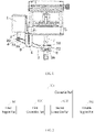
- FIG. 13 is a schematic block diagram of a cap removal device provided by an embodiment of the present invention.
- the cap removal device comprises a control unit 10, a drive part 1, a connection shaft 2 and a cap removal member 3.
- the drive part 1 drives the connection shaft 2 to move upward under the control of the control unit 10, thereby driving the cap removal member 3 whose one end is pivotally connected to the connection shaft to rotate around a fixed pivot point, and further allowing the other end of the cap removal member 3 to move downward to knock off the cap.
- cap removal device is shown and described herein for use with a thrombelastography device, those skilled in the art will recognize that the cap removal device of various embodiments of the present invention may be used with other instrument devices as well.
- the cap 5 sleeves a rotary shaft 7, the second end 32 is provided with an opening 34, and the rotary shaft 7 passes through the opening 34 in a manner substantially perpendicular to the second end 32, such that the second end 32 sleeves the rotary shaft 7, and the cap 5 is located below the opening 34 on the rotary shaft 7.
- a hole is formed in the center of the cap 5 and allows the rotary shaft 7 to pass through, wherein the diameter of the hole is slightly smaller than the diameter of the rotary shaft 7 in a natural state.
- the cap 5 is made of a material having appropriate flexibility, so that the cap can be sleeved and pressed against the rotary shaft 7, and can be removed from the rotary shaft 7 while being subjected to an appropriate external force.
- the width of the opening 34 is larger than the diameter of the rotary shaft 7, that is, the opening 34 sleeves the rotary shaft 7 and does not contact the rotary shaft 7 when moving or being stationary, thereby avoiding the interference to the rotational movement of the rotary shaft 7 when the opening 34 is in contact with the rotary shaft 7 in case that the rotary shaft 7 rotates.
- the width of the opening 34 should be not larger than the diameter of the cap 5, i.e., when the second end 32 of the cap removal member 3 moves downward, the opening of the second end 32 can be ensured to come into contact with the cap 5, thereby removing the cap 5.
- the size of the opening 34 is adjustable.
- the shape of the lower end surface of the second end 32 of the cap removal member 3 may be set to be substantially consistent with the shape of the cap 5, thereby maximizing the contact area between the second end 32 and the cap 5, so that the cap 5 can be removed from the rotary shaft 7 more easily.
- the rotary shaft 7 is supported by the support 8.
- the drive part 1 is fixed to a support 8, and the cap removal member 3 is pivotally connected to the support 8 at the pivot point 4.
- the cap removal member 3 is connected to the support 8 through a connection member.
- the connection member is fixedly connected to the support 8, and the cap removal member 3 is pivotally connected to the connection member at the pivot point 4.
- the drive part 1 is fixedly connected to one side of the support 8, and ensures that the drive part 1 can drive the connection shaft 2 to move upward and downward relative to the support 8 in a vertical direction.
- the pivot point 4 of the cap removal member 3 which is pivotally connected to the rotary shaft 2 is pivotally connected to the lower part (or the connection member) of the support 8.
- the rotary shaft 7 is supported on the support 8 in a vertically downward manner.
- the opening 34 of the second end 32 of the cap removal member 3 sleeves a position, close to the tail end, of the rotary shaft 7.
- the cap 5 sleeves the rotary shaft 7, and is located below the opening 34.
- the control unit is configured to, in response to a cap removal request, control the drive part 1 to drive the connection shaft 2 to move upward.
- the first end 31 of the cap removal member 3, which is connected to the connection shaft 2 is pulled upward, thereby driving the cap removal member 3 to rotate around the pivot point 4.
- the second end 32 moves downward till contacting the cap 5.
- the lower end surface of the second end 32 is in contact with the top surface of the cap 5 and presses the cap 5, such that the cap 5 is removed from the rotary shaft 7, thereby completing the cap removal operation of the cap removal member 3.
- connection shaft 2 may be driven downward by the control unit before the next cap removal operation is required.
- the connection shaft 2 moves downward, the first end 31 of the cap removal member 3, which is connected to the connection shaft 2, moves downward together to drive the cap removal member 3 to rotate around the pivot point 4.
- the second end 32 moves upward substantially along the rotary shaft 7 to an initial position, thereby completing a resetting operation of the cap removal member 3.
- An embodiment of the present invention provides a thrombelastography device.
- the thrombelastography device comprises a support 8, a rotary shaft 7 and the cap removal device, wherein
- the support comprises a fixed support part 101, a movable support part 102, a first connection part 1031 and a second connection part 1032, wherein
- the fixed support part 101 supports the movable support part and the supported object by means of the connection part
- the first connection part 1031 and the second connection part 1032 in the connection part are connected together in a form of point contact
- the supported object which is in stress drives the movable support part 102 to rotate around the contact point between the first connection part 1031 and the second connection part 1032. Since the first connection part 1031 and the second connection part 1032 are connected together in a form of point contact, when the movable support part 102 and the fixed support part 101 rotate relative to each other, only one contact point generates a frictional force to impede the rotation of the movable support part 102. Therefore, the frictional force generated on the support may be reduced, and further the rotational resistance encountered when the supported object rotates is reduced.
- the point connection may resides in that: two contact components are not in full contact and the contact area is less than a predetermined value.
- the contact area is less than 1 square millimeter.
- the first connection part 1031 comprises a jewel bearing 3031
- the second connection part 1032 comprises a top cone 3032
- the jewel bearing 3031 is of a cake structure.
- the tapered groove 2011 is formed in a plane of the jewel bearing 3031.
- the top cone 3032 may be of a tapered structure.
- the tip of the top cone 3032 is located in the groove 2011, and only the tip of the top cone 3032 is in contact with the bottom of the groove 2011, such that the jewel bearing 3031 is connected to the top cone 3032 in a form of point contact.
- the tip of the top cone 3032 has an area of 0.8 square millimeter
- the top cone is connected to the tapered groove 2011 of the jewel bearing 3031 in a form of point contact by means of this tip having the area of 0.8 square millimeter.
- the first connection part in the connection part may be a jewel bearing or a top cone.
- the second connection part is a top cone.
- the first connection part is the top cone
- the second connection part is the jewel bearing.
- the jewel bearing 3031 which serves as the first connection part is fixedly connected to the fixed support part 101
- the top cone 3032 which serves as the second connection part is fixedly connected to the movable support part 102
- the tip of the top cone 3032 is located in a groove of the jewel bearing 3031 and is in point contact with the bottom of the groove of the jewel bearing 3031.
- the fixed support part 101 supports, by means of the jewel bearing 3031, the top cone 3032 and the movable support part 102 which are fixedly connected.
- the top cone 3031 which serves as the first connection part is fixedly connected to the fixed support part 101
- the jewel bearing 3032 which serves as the second connection part is fixedly connected to the movable support part 102
- the tip of the top cone 3031 is in point contact with the bottom of the jewel bearing 3032.
- the fixed support part 101 supports, by means of the top cone 3031, the jewel bearing 3032 and the movable support part 102 which are fixedly connected.
- the support further comprises at least a pair of magnets
- the support comprises two pairs of magnets.
- the first pair of magnets includes a magnet 5041 and a magnet 5042.
- the second pair of magnets includes a magnet 5051 and a magnet 5052.
- the magnet 5041 and the magnet 5051 are fixed to the fixed support part 101, and the magnet 5042 and the magnet 5052 are fixed to the movable support part 102.
- the magnet 5041 and the magnet 5042 in the first pair of magnets are stacked in parallel.
- the surfaces, which are close to each other, of the magnet 5041 and the magnet 5042 have magnetic poles which have the same polarity, for example, the N pole of the magnet 5041 is directed to the movable support part 102, and the N pole of the magnet 5042 is directed to the fixed support part 101; the magnet 5051 and the magnet 5052 in the second pair of magnets are stacked in parallel; the surfaces, which are close to each other, of the magnet 5051 and the magnet 5052 have magnetic poles which have the same polarity, for example, the S pole of the magnet 5051 is directed to the movable support part 102, and the S pole of the magnet 5052 is directed to the fixed support part 101.
- the thrombelastography device further comprises a measurement device which is used for measuring a rotation angle of the rotary shaft, and forming a thrombelastogram corresponding to measured blood according to the rotation angle of the rotary shaft.
- the measurement device comprises at least one reflective sheet 51, at least one light emitting module 52, at least one light receiving module 53 and a processing module 54, wherein
- the reflective sheet reflects the light emitted by the light emitting module to the light receiving module.
- the reflective sheet rotates under the driving of the rotary shaft, since the light emitting module emits light in a fixed direction, the amount of light received by the reflective sheet changes, and at the same time, the optical path of light reflected by the reflective sheet changes due to the rotation of the reflective sheet, resulting in a change in the intensity of light received by the light receiving module that receives the light in the fixed direction.
- the light receiving module converts the received light into a corresponding electrical signal according to the intensity of the light.
- the processing module determines the rotation angle of the rotary shaft according to the electrical signal.
- the light is taken as a signal for detecting the rotation angle of the rotary shaft. Since the intensity of the light does not change as external factors such as temperature change, the accuracy of detecting the rotation angle of the rotary shaft can be improved by detecting the rotation angle of the rotary shaft through light.
- the light emitting module 52 comprises a light emitting diode 6031 and a light guide column 6032, wherein the light emitting diode 6031 emits light to the reflective sheet 51 through the light guide column 6032; and/or the light receiving module 53 comprises a photocell 6041 and a light guide column 6042, wherein the photocell 6041 receives light reflected by the reflective sheet 51 through the light guide column 6042.
- the inner surface of a second through hole 6062 is a machined surface which has a certain roughness, if the light emitting diode 6031 directly emits light to the reflective sheet 51, the light emitted by the light emitting diode 6031 will be diffusely reflected within the second through hole 6062, resulting in loss of light energy on the one hand, and difficulty in control over the direction and amount of light outgoing from the second through hole 6062 on the other hand.
- the light emitted from the light emitting diode 6031 is directed to the reflective sheet 51 through the light guide column 6032.
- the light emitted from the light emitting diode 6031 is conducted inside the light guide column 6032, and may not be diffusely reflected, thereby improving the utilization rate of the light energy and ensuring that the light emitted from the second through hole 6062 has a specific direction and a specific amount, and further ensuring the accuracy of detecting the rotation angle of the rotary shaft 7.
- each of the light receiving modules comprises a photocell and a light guide column which are fixed in a third through hole respectively, wherein the light guide column is located close to one of the reflective sheets.
- the light guide column receives the light reflected by the corresponding reflective sheet in a fixed direction, and transmits the received light to the photocell.
- the photocell converts the received light into a corresponding electrical signal according to the intensity of the light.
- the inner surface of the third through hole 6063 has a certain roughness. If the light reflected by the reflective sheet 51 directly enters the third through hole 6063 and reaches the photocell 6041, the light will be diffusely reflected on the inner wall of the third through hole 6063, resulting in the loss of light energy. The energy of the light finally reaching the photocell 6041 is less than the energy of the light entering the third through hole 6063, resulting in a relatively large error in the finally detected rotation angle of the rotary shaft 7.
- the light reflected by the reflective sheet 51 is received by the light guide column 6042, and the light is transmitted inside the light guide column 6042 and is not diffusely reflected during the transmission, thereby ensuring that the energy of the light received by the photocell 6041 is equal to the energy of light reflected by the reflective sheet 51 to the light guide column 6042, and further ensuring the accuracy of detecting the rotation angle of the rotary shaft 7.
- the thrombelastography device further includes at least one light blocking sheet, the number of the light blocking sheets being equal to the number of the light guide columns, and each of the light blocking sheets corresponding to one of the light guide columns.
- Each light blocking sheet is provided with a light passing hole having a fixed shape and a fixed size. The light blocking sheet is arranged between the reflective sheet and the light guide column, so that the light reflected by the reflective sheet can only be emitted to the light guide column through the light passing hole in the light blocking sheet.
- the thrombelastography device further comprises a position correction device 9, wherein
- the present invention provides a thrombelastography device, wherein the rotary shaft is able to rotate under the support of the support, and the position correction device is connected to the rotary shaft.
- the position correction device When the rotary shaft rotates away from a balanced position under the driving force of the measured blood, the position correction device is caused to generate an acting force for rotating the rotary shaft towards the balanced position.
- the driving effect of the measured blood on the rotary shaft is removed, if the position where the rotary shaft is located is not the balanced position, the rotary shaft automatically returns to the balanced position under the acting force of the position correction device, and thus does not need to be calibrated by manual adjustment. Therefore, the time of calibrating the rotary shaft is saved, and the efficiency in blood coagulation measurement is improved.
- the position correction device may comprise at least one hair spring 703, wherein an inner ring of the hair spring 703 is fixedly connected to an outer circumferential surface of the rotary shaft 7, and an outer ring of the hair spring is fixedly connected to the support 8.
- the hair spring 703 When the rotary shaft 7 is in the balanced position, the hair spring 703 is in a free state, and does not exert an acting force on the rotary shaft 7.
- the hair spring 703 rotates inward to deform or rotates outward to deform.
- the hair spring 703 restores an elastic force after being deformed.
- the function of restoring the elastic force is to restore the rotary shaft 7 to the balanced position, such that the hair spring 703 restores to the free state.
- the spiral direction of at least one of the hair springs 703 from the inner ring to the outer ring is different from the spiral direction of the other hair spring 703 from the inner ring to the outer ring.
- the position correction device comprises a hair spring 8031 and a hair spring 8032, wherein inner rings of the hair spring 8031 and the hair spring 8032 are fixed to the rotary shaft 7 respectively, and outer rings of the hair spring 8031 and the hair spring 8032 are fixed to the support 8 respectively.
- the spiral direction of the hair spring 8031 from the inner ring to the outer ring is clockwise
- the spiral direction of the hair spring 8032 from the inner ring to the outer ring is counterclockwise.
- the hair spring Since the hair spring outputs a stable acting force when it is screwed than the acting force output when it is unscrewed, the hair spring is set to a different spiral direction.
- the rotary shaft rotates in different directions, there is always a corresponding hair spring that is screwed to provide an acting force for the rotary shaft to restore to the balanced position.
- the position correction device further comprises at least one zero setting module, wherein each zero setting module corresponds to one hair spring.
- Each zero setting module corresponds to one hair spring.
- One end of each zero setting module is fixedly connected to the support, and the other end of the zero setting module is fixedly connected to different positions on the outer ring of the corresponding hair spring in an adjustable manner, so as to adjust the balanced position.
- the position correction device comprises a hair spring 8031, a hair spring 8032, a zero setting device 9033, and a zero setting device 9034, wherein the hair spring 8031 corresponds to the zero setting device 9033, and the hair spring 8032 corresponds to the zero setting device 9034.
- One end of the zero setting device 9033 is fixedly connected to the support 8, and the other end of the zero setting device 9033 is fixed to the outer ring of the hair spring 8031 by a U-shaped structure.
- a position, which is fixed to the U-shaped structure, on the outer ring of the hair spring 8031 is adjustable.
- One end of the zero setting device 9034 is fixedly connected to the support 8, and the other end of the zero setting device is fixed to the outer ring of the hair spring 8032 by a U-shaped structure.
- a position, which is fixed to the U-shaped structure, on the outer ring of the hair spring 8032 is adjustable.
- the inner rings of the hair spring 8031 and the hair spring 8032 are fixed to the outer circumferential surface of the rotary shaft 7.
- the acting force applied by the two hair springs on the rotary shaft 7 when the rotary shaft 7 is not subjected to an external driving force is changed, and the balanced position of the rotary shaft 7 is adjusted, such that the balanced position of the rotary shaft 7 is corrected when the balanced position of the rotary shaft 7 deviates from a target position.
- processor processing unit/module
- controller control unit/module
- these appropriate devices may be software, hardware, firmware, or a combination thereof, such as, for example, a computer, a central processing unit, or the like. They may be composed of single components or dispersed over a plurality of components according to their functions. They may be a centralized processing system or a distributed processing system.
Landscapes
- Health & Medical Sciences (AREA)
- Life Sciences & Earth Sciences (AREA)
- Engineering & Computer Science (AREA)
- Hematology (AREA)
- Biomedical Technology (AREA)
- Chemical & Material Sciences (AREA)
- Immunology (AREA)
- Physics & Mathematics (AREA)
- Molecular Biology (AREA)
- Urology & Nephrology (AREA)
- Medicinal Chemistry (AREA)
- Pathology (AREA)
- Food Science & Technology (AREA)
- Analytical Chemistry (AREA)
- Biochemistry (AREA)
- General Health & Medical Sciences (AREA)
- General Physics & Mathematics (AREA)
- Biotechnology (AREA)
- Ecology (AREA)
- Biophysics (AREA)
- Cell Biology (AREA)
- Microbiology (AREA)
- Mechanical Engineering (AREA)
- Investigating Or Analysing Biological Materials (AREA)
- Transmission Devices (AREA)
- Rolling Contact Bearings (AREA)
- Devices For Opening Bottles Or Cans (AREA)
Applications Claiming Priority (8)
| Application Number | Priority Date | Filing Date | Title |
|---|---|---|---|
| CN201620383166.0U CN205749523U (zh) | 2016-04-29 | 2016-04-29 | 血栓弹力仪 |
| CN201620380641.9U CN205744966U (zh) | 2016-04-29 | 2016-04-29 | 一种支架、血栓弹力仪及支撑系统 |
| CN201610278393.1A CN105807039B (zh) | 2016-04-29 | 2016-04-29 | 血栓弹力仪 |
| CN201610278391.2A CN105805176B (zh) | 2016-04-29 | 2016-04-29 | 一种支架、血栓弹力仪及支撑系统 |
| CN201620380387.2U CN205720232U (zh) | 2016-04-29 | 2016-04-29 | 一种血栓弹力仪 |
| CN201610279824.6A CN105842432B (zh) | 2016-04-29 | 2016-04-29 | 一种血栓弹力仪 |
| PCT/CN2017/082785 WO2017186189A1 (zh) | 2016-04-29 | 2017-05-02 | 一种脱盖装置及具有该装置的血栓弹力仪 |
| EP17788841.9A EP3450983B1 (de) | 2016-04-29 | 2017-05-02 | Thrombelastografievorrichtung mit kappenentfernungsvorrichtung |
Related Parent Applications (1)
| Application Number | Title | Priority Date | Filing Date |
|---|---|---|---|
| EP17788841.9A Division EP3450983B1 (de) | 2016-04-29 | 2017-05-02 | Thrombelastografievorrichtung mit kappenentfernungsvorrichtung |
Publications (3)
| Publication Number | Publication Date |
|---|---|
| EP4019969A2 true EP4019969A2 (de) | 2022-06-29 |
| EP4019969A3 EP4019969A3 (de) | 2022-08-03 |
| EP4019969B1 EP4019969B1 (de) | 2024-09-18 |
Family
ID=60160721
Family Applications (2)
| Application Number | Title | Priority Date | Filing Date |
|---|---|---|---|
| EP17788841.9A Active EP3450983B1 (de) | 2016-04-29 | 2017-05-02 | Thrombelastografievorrichtung mit kappenentfernungsvorrichtung |
| EP21209996.4A Active EP4019969B1 (de) | 2016-04-29 | 2017-05-02 | Kappenentfernungsvorrichtung und thrombelastografievorrichtung damit |
Family Applications Before (1)
| Application Number | Title | Priority Date | Filing Date |
|---|---|---|---|
| EP17788841.9A Active EP3450983B1 (de) | 2016-04-29 | 2017-05-02 | Thrombelastografievorrichtung mit kappenentfernungsvorrichtung |
Country Status (4)
| Country | Link |
|---|---|
| US (2) | US10759642B2 (de) |
| EP (2) | EP3450983B1 (de) |
| JP (1) | JP6924257B2 (de) |
| WO (1) | WO2017186189A1 (de) |
Families Citing this family (1)
| Publication number | Priority date | Publication date | Assignee | Title |
|---|---|---|---|---|
| CN111707814B (zh) * | 2020-07-16 | 2023-11-07 | 广州万孚生物技术股份有限公司 | 一种血栓弹力分析装置及方法 |
Family Cites Families (15)
| Publication number | Priority date | Publication date | Assignee | Title |
|---|---|---|---|---|
| IE871252L (en) * | 1987-05-14 | 1988-11-14 | Ferrosan Ab | A viscometer |
| US6225126B1 (en) | 1999-02-22 | 2001-05-01 | Haemoscope Corporation | Method and apparatus for measuring hemostasis |
| DE19917646B4 (de) * | 1999-04-19 | 2013-06-20 | Siemens Healthcare Diagnostics Products Gmbh | Verschlußvorrichtung für Reagenzbehälter |
| DE102008038067A1 (de) * | 2008-08-16 | 2010-02-18 | Schaeffler Kg | Lagerungsanordnung für einen Maschinentisch mit magnetischer Entlastung |
| US8448499B2 (en) * | 2008-12-23 | 2013-05-28 | C A Casyso Ag | Cartridge device for a measuring system for measuring viscoelastic characteristics of a sample liquid, a corresponding measuring system, and a corresponding method |
| WO2010081876A1 (en) * | 2009-01-16 | 2010-07-22 | C A Casyso Ag | A measuring unit for measuring characteristics of a sample liquid, in particular viscoelastic characteristics of a blood sample |
| EP2208996B1 (de) * | 2009-01-16 | 2010-09-01 | C A Casyso AG | Messeinheit zum Messen der Eigenschaften einer Probenflüssigkeit, insbesondere der viskoelastischen Eigenschaften einer Blutprobe |
| CN103011040B (zh) * | 2012-12-21 | 2015-04-15 | 重庆大学 | 真空采血容器器盖自动开启装置 |
| CN103398922B (zh) * | 2013-07-09 | 2015-09-30 | 广东石油化工学院 | 一种血栓弹力测量装置及其测量方法 |
| CN104614539A (zh) * | 2013-11-05 | 2015-05-13 | 北京乐普医疗科技有限责任公司 | 一种血栓弹力图仪 |
| JP2015105948A (ja) * | 2013-11-28 | 2015-06-08 | 株式会社野毛電気工業 | 尿流量計測装置および尿流量計測データ処理システム |
| CN104062207B (zh) * | 2014-07-15 | 2016-05-11 | 中国科学院苏州生物医学工程技术研究所 | 一种血液粘弹力监测装置 |
| CN104181311B (zh) * | 2014-08-22 | 2016-02-03 | 中国科学院苏州生物医学工程技术研究所 | 一种血栓弹力测试装置 |
| US10816559B2 (en) * | 2014-09-29 | 2020-10-27 | Ca Casyso Ag | Blood testing system and method |
| CN104458503B (zh) * | 2014-12-12 | 2016-11-30 | 广州阳普医疗科技股份有限公司 | 一种凝血检测仪器 |
-
2017
- 2017-05-02 JP JP2019507985A patent/JP6924257B2/ja active Active
- 2017-05-02 EP EP17788841.9A patent/EP3450983B1/de active Active
- 2017-05-02 EP EP21209996.4A patent/EP4019969B1/de active Active
- 2017-05-02 WO PCT/CN2017/082785 patent/WO2017186189A1/zh not_active Ceased
- 2017-05-02 US US16/097,556 patent/US10759642B2/en active Active
-
2020
- 2020-08-28 US US17/006,535 patent/US11866311B2/en active Active
Also Published As
| Publication number | Publication date |
|---|---|
| US20190210856A1 (en) | 2019-07-11 |
| EP4019969A3 (de) | 2022-08-03 |
| EP3450983A4 (de) | 2020-03-04 |
| EP3450983A1 (de) | 2019-03-06 |
| EP3450983B1 (de) | 2021-11-24 |
| US11866311B2 (en) | 2024-01-09 |
| JP6924257B2 (ja) | 2021-08-25 |
| JP2019515314A (ja) | 2019-06-06 |
| WO2017186189A1 (zh) | 2017-11-02 |
| US10759642B2 (en) | 2020-09-01 |
| US20210002116A1 (en) | 2021-01-07 |
| EP4019969B1 (de) | 2024-09-18 |
Similar Documents
| Publication | Publication Date | Title |
|---|---|---|
| US9182226B2 (en) | Hand-held laser distance measuring device | |
| CN204065105U (zh) | 一种血栓弹力测试装置 | |
| CN104181311A (zh) | 一种血栓弹力测试装置 | |
| CN105807039B (zh) | 血栓弹力仪 | |
| US11866311B2 (en) | Cap removal device and thrombelastography device having same | |
| CN104568237A (zh) | 一种杠杆式压力传感器 | |
| JP2012215572A (ja) | ハンドヘルド色測定装置 | |
| CN110763201B (zh) | 一种倾斜检测装置 | |
| CN206974414U (zh) | 一种自动精平水准仪 | |
| JP2019033170A5 (de) | ||
| CN205749523U (zh) | 血栓弹力仪 | |
| CN110864985A (zh) | 一种用于蠕变疲劳试验机的引伸计对准调整装置 | |
| JP2013226212A (ja) | 点滴検知装置 | |
| US11067490B2 (en) | Bracket, support system, and thrombelastography device and use method thereof | |
| JP2015219169A (ja) | 真円度測定用プローブ、真円度測定装置、及び真円度測定方法 | |
| CN211235340U (zh) | 一种用于蠕变疲劳试验机的引伸计调节对准装置 | |
| JP2005331350A (ja) | 水準器およびレーザー墨出し装置 | |
| US20250387874A1 (en) | Devices, systems, and methods for skate blade alignment in a skate sharpening system | |
| CN215458098U (zh) | 束光器的叶片调节机构及束光器 | |
| CN104132633A (zh) | 可测量极坐标的装置 | |
| US20190120820A1 (en) | Thrombelastography device, heating apparatus, blood coagulation analysis system and rotational angle measurement method | |
| CN211121197U (zh) | 一种水平尺的铅垂精度调整设备 | |
| CN204705714U (zh) | 激光测距仪 | |
| JP2015019817A (ja) | 遊技機用傾斜角度調整装置 | |
| JPH0545703A (ja) | 測距用投光器の取付け装置 |
Legal Events
| Date | Code | Title | Description |
|---|---|---|---|
| PUAI | Public reference made under article 153(3) epc to a published international application that has entered the european phase |
Free format text: ORIGINAL CODE: 0009012 |
|
| STAA | Information on the status of an ep patent application or granted ep patent |
Free format text: STATUS: THE APPLICATION HAS BEEN PUBLISHED |
|
| AC | Divisional application: reference to earlier application |
Ref document number: 3450983 Country of ref document: EP Kind code of ref document: P |
|
| AK | Designated contracting states |
Kind code of ref document: A2 Designated state(s): AL AT BE BG CH CY CZ DE DK EE ES FI FR GB GR HR HU IE IS IT LI LT LU LV MC MK MT NL NO PL PT RO RS SE SI SK SM TR |
|
| PUAL | Search report despatched |
Free format text: ORIGINAL CODE: 0009013 |
|
| AK | Designated contracting states |
Kind code of ref document: A3 Designated state(s): AL AT BE BG CH CY CZ DE DK EE ES FI FR GB GR HR HU IE IS IT LI LT LU LV MC MK MT NL NO PL PT RO RS SE SI SK SM TR |
|
| RIC1 | Information provided on ipc code assigned before grant |
Ipc: B67B 3/28 20060101ALI20220630BHEP Ipc: G01N 33/86 20060101ALI20220630BHEP Ipc: G01N 33/49 20060101AFI20220630BHEP |
|
| STAA | Information on the status of an ep patent application or granted ep patent |
Free format text: STATUS: REQUEST FOR EXAMINATION WAS MADE |
|
| 17P | Request for examination filed |
Effective date: 20230203 |
|
| RBV | Designated contracting states (corrected) |
Designated state(s): AL AT BE BG CH CY CZ DE DK EE ES FI FR GB GR HR HU IE IS IT LI LT LU LV MC MK MT NL NO PL PT RO RS SE SI SK SM TR |
|
| STAA | Information on the status of an ep patent application or granted ep patent |
Free format text: STATUS: EXAMINATION IS IN PROGRESS |
|
| 17Q | First examination report despatched |
Effective date: 20230404 |
|
| P01 | Opt-out of the competence of the unified patent court (upc) registered |
Effective date: 20230523 |
|
| GRAP | Despatch of communication of intention to grant a patent |
Free format text: ORIGINAL CODE: EPIDOSNIGR1 |
|
| STAA | Information on the status of an ep patent application or granted ep patent |
Free format text: STATUS: GRANT OF PATENT IS INTENDED |
|
| INTG | Intention to grant announced |
Effective date: 20240412 |
|
| GRAS | Grant fee paid |
Free format text: ORIGINAL CODE: EPIDOSNIGR3 |
|
| GRAA | (expected) grant |
Free format text: ORIGINAL CODE: 0009210 |
|
| STAA | Information on the status of an ep patent application or granted ep patent |
Free format text: STATUS: THE PATENT HAS BEEN GRANTED |
|
| AC | Divisional application: reference to earlier application |
Ref document number: 3450983 Country of ref document: EP Kind code of ref document: P |
|
| AK | Designated contracting states |
Kind code of ref document: B1 Designated state(s): AL AT BE BG CH CY CZ DE DK EE ES FI FR GB GR HR HU IE IS IT LI LT LU LV MC MK MT NL NO PL PT RO RS SE SI SK SM TR |
|
| REG | Reference to a national code |
Ref country code: GB Ref legal event code: FG4D |
|
| REG | Reference to a national code |
Ref country code: CH Ref legal event code: EP |
|
| REG | Reference to a national code |
Ref country code: IE Ref legal event code: FG4D |
|
| REG | Reference to a national code |
Ref country code: DE Ref legal event code: R096 Ref document number: 602017085007 Country of ref document: DE |
|
| REG | Reference to a national code |
Ref country code: LT Ref legal event code: MG9D |
|
| PG25 | Lapsed in a contracting state [announced via postgrant information from national office to epo] |
Ref country code: NO Free format text: LAPSE BECAUSE OF FAILURE TO SUBMIT A TRANSLATION OF THE DESCRIPTION OR TO PAY THE FEE WITHIN THE PRESCRIBED TIME-LIMIT Effective date: 20241218 |
|
| PG25 | Lapsed in a contracting state [announced via postgrant information from national office to epo] |
Ref country code: GR Free format text: LAPSE BECAUSE OF FAILURE TO SUBMIT A TRANSLATION OF THE DESCRIPTION OR TO PAY THE FEE WITHIN THE PRESCRIBED TIME-LIMIT Effective date: 20241219 Ref country code: FI Free format text: LAPSE BECAUSE OF FAILURE TO SUBMIT A TRANSLATION OF THE DESCRIPTION OR TO PAY THE FEE WITHIN THE PRESCRIBED TIME-LIMIT Effective date: 20240918 |
|
| PG25 | Lapsed in a contracting state [announced via postgrant information from national office to epo] |
Ref country code: BG Free format text: LAPSE BECAUSE OF FAILURE TO SUBMIT A TRANSLATION OF THE DESCRIPTION OR TO PAY THE FEE WITHIN THE PRESCRIBED TIME-LIMIT Effective date: 20240918 |
|
| PG25 | Lapsed in a contracting state [announced via postgrant information from national office to epo] |
Ref country code: LV Free format text: LAPSE BECAUSE OF FAILURE TO SUBMIT A TRANSLATION OF THE DESCRIPTION OR TO PAY THE FEE WITHIN THE PRESCRIBED TIME-LIMIT Effective date: 20240918 |
|
| PG25 | Lapsed in a contracting state [announced via postgrant information from national office to epo] |
Ref country code: HR Free format text: LAPSE BECAUSE OF FAILURE TO SUBMIT A TRANSLATION OF THE DESCRIPTION OR TO PAY THE FEE WITHIN THE PRESCRIBED TIME-LIMIT Effective date: 20240918 |
|
| REG | Reference to a national code |
Ref country code: NL Ref legal event code: MP Effective date: 20240918 |
|
| PG25 | Lapsed in a contracting state [announced via postgrant information from national office to epo] |
Ref country code: RS Free format text: LAPSE BECAUSE OF FAILURE TO SUBMIT A TRANSLATION OF THE DESCRIPTION OR TO PAY THE FEE WITHIN THE PRESCRIBED TIME-LIMIT Effective date: 20241218 |
|
| PG25 | Lapsed in a contracting state [announced via postgrant information from national office to epo] |
Ref country code: RS Free format text: LAPSE BECAUSE OF FAILURE TO SUBMIT A TRANSLATION OF THE DESCRIPTION OR TO PAY THE FEE WITHIN THE PRESCRIBED TIME-LIMIT Effective date: 20241218 Ref country code: NO Free format text: LAPSE BECAUSE OF FAILURE TO SUBMIT A TRANSLATION OF THE DESCRIPTION OR TO PAY THE FEE WITHIN THE PRESCRIBED TIME-LIMIT Effective date: 20241218 Ref country code: LV Free format text: LAPSE BECAUSE OF FAILURE TO SUBMIT A TRANSLATION OF THE DESCRIPTION OR TO PAY THE FEE WITHIN THE PRESCRIBED TIME-LIMIT Effective date: 20240918 Ref country code: HR Free format text: LAPSE BECAUSE OF FAILURE TO SUBMIT A TRANSLATION OF THE DESCRIPTION OR TO PAY THE FEE WITHIN THE PRESCRIBED TIME-LIMIT Effective date: 20240918 Ref country code: GR Free format text: LAPSE BECAUSE OF FAILURE TO SUBMIT A TRANSLATION OF THE DESCRIPTION OR TO PAY THE FEE WITHIN THE PRESCRIBED TIME-LIMIT Effective date: 20241219 Ref country code: FI Free format text: LAPSE BECAUSE OF FAILURE TO SUBMIT A TRANSLATION OF THE DESCRIPTION OR TO PAY THE FEE WITHIN THE PRESCRIBED TIME-LIMIT Effective date: 20240918 Ref country code: BG Free format text: LAPSE BECAUSE OF FAILURE TO SUBMIT A TRANSLATION OF THE DESCRIPTION OR TO PAY THE FEE WITHIN THE PRESCRIBED TIME-LIMIT Effective date: 20240918 |
|
| REG | Reference to a national code |
Ref country code: AT Ref legal event code: MK05 Ref document number: 1725118 Country of ref document: AT Kind code of ref document: T Effective date: 20240918 |
|
| PG25 | Lapsed in a contracting state [announced via postgrant information from national office to epo] |
Ref country code: NL Free format text: LAPSE BECAUSE OF FAILURE TO SUBMIT A TRANSLATION OF THE DESCRIPTION OR TO PAY THE FEE WITHIN THE PRESCRIBED TIME-LIMIT Effective date: 20240918 |
|
| PG25 | Lapsed in a contracting state [announced via postgrant information from national office to epo] |
Ref country code: IS Free format text: LAPSE BECAUSE OF FAILURE TO SUBMIT A TRANSLATION OF THE DESCRIPTION OR TO PAY THE FEE WITHIN THE PRESCRIBED TIME-LIMIT Effective date: 20250118 Ref country code: PT Free format text: LAPSE BECAUSE OF FAILURE TO SUBMIT A TRANSLATION OF THE DESCRIPTION OR TO PAY THE FEE WITHIN THE PRESCRIBED TIME-LIMIT Effective date: 20250120 |
|
| PG25 | Lapsed in a contracting state [announced via postgrant information from national office to epo] |
Ref country code: SM Free format text: LAPSE BECAUSE OF FAILURE TO SUBMIT A TRANSLATION OF THE DESCRIPTION OR TO PAY THE FEE WITHIN THE PRESCRIBED TIME-LIMIT Effective date: 20240918 Ref country code: RO Free format text: LAPSE BECAUSE OF FAILURE TO SUBMIT A TRANSLATION OF THE DESCRIPTION OR TO PAY THE FEE WITHIN THE PRESCRIBED TIME-LIMIT Effective date: 20240918 |
|
| PG25 | Lapsed in a contracting state [announced via postgrant information from national office to epo] |
Ref country code: ES Free format text: LAPSE BECAUSE OF FAILURE TO SUBMIT A TRANSLATION OF THE DESCRIPTION OR TO PAY THE FEE WITHIN THE PRESCRIBED TIME-LIMIT Effective date: 20240918 |
|
| PG25 | Lapsed in a contracting state [announced via postgrant information from national office to epo] |
Ref country code: EE Free format text: LAPSE BECAUSE OF FAILURE TO SUBMIT A TRANSLATION OF THE DESCRIPTION OR TO PAY THE FEE WITHIN THE PRESCRIBED TIME-LIMIT Effective date: 20240918 Ref country code: AT Free format text: LAPSE BECAUSE OF FAILURE TO SUBMIT A TRANSLATION OF THE DESCRIPTION OR TO PAY THE FEE WITHIN THE PRESCRIBED TIME-LIMIT Effective date: 20240918 |
|
| PG25 | Lapsed in a contracting state [announced via postgrant information from national office to epo] |
Ref country code: CZ Free format text: LAPSE BECAUSE OF FAILURE TO SUBMIT A TRANSLATION OF THE DESCRIPTION OR TO PAY THE FEE WITHIN THE PRESCRIBED TIME-LIMIT Effective date: 20240918 Ref country code: PL Free format text: LAPSE BECAUSE OF FAILURE TO SUBMIT A TRANSLATION OF THE DESCRIPTION OR TO PAY THE FEE WITHIN THE PRESCRIBED TIME-LIMIT Effective date: 20240918 |
|
| PG25 | Lapsed in a contracting state [announced via postgrant information from national office to epo] |
Ref country code: IT Free format text: LAPSE BECAUSE OF FAILURE TO SUBMIT A TRANSLATION OF THE DESCRIPTION OR TO PAY THE FEE WITHIN THE PRESCRIBED TIME-LIMIT Effective date: 20240918 Ref country code: SK Free format text: LAPSE BECAUSE OF FAILURE TO SUBMIT A TRANSLATION OF THE DESCRIPTION OR TO PAY THE FEE WITHIN THE PRESCRIBED TIME-LIMIT Effective date: 20240918 |
|
| REG | Reference to a national code |
Ref country code: DE Ref legal event code: R081 Ref document number: 602017085007 Country of ref document: DE Owner name: HAEMONETICS CORPORATION, BOSTON, US Free format text: FORMER OWNER: NEOTEK BIOSCIENCE CO., LTD., SUZHOU, JIANGSU, CN |
|
| REG | Reference to a national code |
Ref country code: DE Ref legal event code: R097 Ref document number: 602017085007 Country of ref document: DE |
|
| RAP2 | Party data changed (patent owner data changed or rights of a patent transferred) |
Owner name: HAEMONETICS CORPORATION |
|
| PGFP | Annual fee paid to national office [announced via postgrant information from national office to epo] |
Ref country code: DE Payment date: 20250529 Year of fee payment: 9 |
|
| PG25 | Lapsed in a contracting state [announced via postgrant information from national office to epo] |
Ref country code: DK Free format text: LAPSE BECAUSE OF FAILURE TO SUBMIT A TRANSLATION OF THE DESCRIPTION OR TO PAY THE FEE WITHIN THE PRESCRIBED TIME-LIMIT Effective date: 20240918 |
|
| PGFP | Annual fee paid to national office [announced via postgrant information from national office to epo] |
Ref country code: FR Payment date: 20250526 Year of fee payment: 9 |
|
| PLBE | No opposition filed within time limit |
Free format text: ORIGINAL CODE: 0009261 |
|
| STAA | Information on the status of an ep patent application or granted ep patent |
Free format text: STATUS: NO OPPOSITION FILED WITHIN TIME LIMIT |
|
| 26N | No opposition filed |
Effective date: 20250619 |
|
| PG25 | Lapsed in a contracting state [announced via postgrant information from national office to epo] |
Ref country code: SE Free format text: LAPSE BECAUSE OF FAILURE TO SUBMIT A TRANSLATION OF THE DESCRIPTION OR TO PAY THE FEE WITHIN THE PRESCRIBED TIME-LIMIT Effective date: 20240918 |
|
| REG | Reference to a national code |
Ref country code: CH Ref legal event code: H13 Free format text: ST27 STATUS EVENT CODE: U-0-0-H10-H13 (AS PROVIDED BY THE NATIONAL OFFICE) Effective date: 20251223 |
|
| PG25 | Lapsed in a contracting state [announced via postgrant information from national office to epo] |
Ref country code: LU Free format text: LAPSE BECAUSE OF NON-PAYMENT OF DUE FEES Effective date: 20250502 |
|
| PG25 | Lapsed in a contracting state [announced via postgrant information from national office to epo] |
Ref country code: CH Free format text: LAPSE BECAUSE OF NON-PAYMENT OF DUE FEES Effective date: 20250531 |
|
| GBPC | Gb: european patent ceased through non-payment of renewal fee |
Effective date: 20250502 |
|
| PG25 | Lapsed in a contracting state [announced via postgrant information from national office to epo] |
Ref country code: MC Free format text: LAPSE BECAUSE OF FAILURE TO SUBMIT A TRANSLATION OF THE DESCRIPTION OR TO PAY THE FEE WITHIN THE PRESCRIBED TIME-LIMIT Effective date: 20240918 |