EP4019879B1 - Wärmetauscher - Google Patents
Wärmetauscher Download PDFInfo
- Publication number
- EP4019879B1 EP4019879B1 EP21217891.7A EP21217891A EP4019879B1 EP 4019879 B1 EP4019879 B1 EP 4019879B1 EP 21217891 A EP21217891 A EP 21217891A EP 4019879 B1 EP4019879 B1 EP 4019879B1
- Authority
- EP
- European Patent Office
- Prior art keywords
- raised
- lines
- valleys
- peaks
- flow channel
- Prior art date
- Legal status (The legal status is an assumption and is not a legal conclusion. Google has not performed a legal analysis and makes no representation as to the accuracy of the status listed.)
- Active
Links
Images


Classifications
-
- F—MECHANICAL ENGINEERING; LIGHTING; HEATING; WEAPONS; BLASTING
- F28—HEAT EXCHANGE IN GENERAL
- F28D—HEAT-EXCHANGE APPARATUS, NOT PROVIDED FOR IN ANOTHER SUBCLASS, IN WHICH THE HEAT-EXCHANGE MEDIA DO NOT COME INTO DIRECT CONTACT
- F28D9/00—Heat-exchange apparatus having stationary plate-like or laminated conduit assemblies for both heat-exchange media, the media being in contact with different sides of a conduit wall
- F28D9/0031—Heat-exchange apparatus having stationary plate-like or laminated conduit assemblies for both heat-exchange media, the media being in contact with different sides of a conduit wall the conduits for one heat-exchange medium being formed by paired plates touching each other
- F28D9/0037—Heat-exchange apparatus having stationary plate-like or laminated conduit assemblies for both heat-exchange media, the media being in contact with different sides of a conduit wall the conduits for one heat-exchange medium being formed by paired plates touching each other the conduits for the other heat-exchange medium also being formed by paired plates touching each other
-
- F—MECHANICAL ENGINEERING; LIGHTING; HEATING; WEAPONS; BLASTING
- F24—HEATING; RANGES; VENTILATING
- F24F—AIR-CONDITIONING; AIR-HUMIDIFICATION; VENTILATION; USE OF AIR CURRENTS FOR SCREENING
- F24F12/00—Use of energy recovery systems in air conditioning, ventilation or screening
- F24F12/001—Use of energy recovery systems in air conditioning, ventilation or screening with heat-exchange between supplied and exhausted air
- F24F12/006—Use of energy recovery systems in air conditioning, ventilation or screening with heat-exchange between supplied and exhausted air using an air-to-air heat exchanger
-
- F—MECHANICAL ENGINEERING; LIGHTING; HEATING; WEAPONS; BLASTING
- F28—HEAT EXCHANGE IN GENERAL
- F28D—HEAT-EXCHANGE APPARATUS, NOT PROVIDED FOR IN ANOTHER SUBCLASS, IN WHICH THE HEAT-EXCHANGE MEDIA DO NOT COME INTO DIRECT CONTACT
- F28D21/00—Heat-exchange apparatus not covered by any of the groups F28D1/00 - F28D20/00
- F28D21/0001—Recuperative heat exchangers
- F28D21/0003—Recuperative heat exchangers the heat being recuperated from exhaust gases
- F28D21/0005—Recuperative heat exchangers the heat being recuperated from exhaust gases for domestic or space-heating systems
- F28D21/0008—Air heaters
-
- F—MECHANICAL ENGINEERING; LIGHTING; HEATING; WEAPONS; BLASTING
- F28—HEAT EXCHANGE IN GENERAL
- F28D—HEAT-EXCHANGE APPARATUS, NOT PROVIDED FOR IN ANOTHER SUBCLASS, IN WHICH THE HEAT-EXCHANGE MEDIA DO NOT COME INTO DIRECT CONTACT
- F28D21/00—Heat-exchange apparatus not covered by any of the groups F28D1/00 - F28D20/00
- F28D21/0001—Recuperative heat exchangers
- F28D21/0014—Recuperative heat exchangers the heat being recuperated from waste air or from vapors
-
- F—MECHANICAL ENGINEERING; LIGHTING; HEATING; WEAPONS; BLASTING
- F28—HEAT EXCHANGE IN GENERAL
- F28D—HEAT-EXCHANGE APPARATUS, NOT PROVIDED FOR IN ANOTHER SUBCLASS, IN WHICH THE HEAT-EXCHANGE MEDIA DO NOT COME INTO DIRECT CONTACT
- F28D9/00—Heat-exchange apparatus having stationary plate-like or laminated conduit assemblies for both heat-exchange media, the media being in contact with different sides of a conduit wall
- F28D9/0062—Heat-exchange apparatus having stationary plate-like or laminated conduit assemblies for both heat-exchange media, the media being in contact with different sides of a conduit wall the conduits for one heat-exchange medium being formed by spaced plates with inserted elements
- F28D9/0068—Heat-exchange apparatus having stationary plate-like or laminated conduit assemblies for both heat-exchange media, the media being in contact with different sides of a conduit wall the conduits for one heat-exchange medium being formed by spaced plates with inserted elements with means for changing flow direction of one heat exchange medium, e.g. using deflecting zones
-
- F—MECHANICAL ENGINEERING; LIGHTING; HEATING; WEAPONS; BLASTING
- F28—HEAT EXCHANGE IN GENERAL
- F28F—DETAILS OF HEAT-EXCHANGE AND HEAT-TRANSFER APPARATUS, OF GENERAL APPLICATION
- F28F17/00—Removing ice or water from heat-exchange apparatus
-
- F—MECHANICAL ENGINEERING; LIGHTING; HEATING; WEAPONS; BLASTING
- F28—HEAT EXCHANGE IN GENERAL
- F28F—DETAILS OF HEAT-EXCHANGE AND HEAT-TRANSFER APPARATUS, OF GENERAL APPLICATION
- F28F21/00—Constructions of heat-exchange apparatus characterised by the selection of particular materials
-
- F—MECHANICAL ENGINEERING; LIGHTING; HEATING; WEAPONS; BLASTING
- F28—HEAT EXCHANGE IN GENERAL
- F28F—DETAILS OF HEAT-EXCHANGE AND HEAT-TRANSFER APPARATUS, OF GENERAL APPLICATION
- F28F3/00—Plate-like or laminated elements; Assemblies of plate-like or laminated elements
- F28F3/02—Elements or assemblies thereof with means for increasing heat-transfer area, e.g. with fins, with recesses, with corrugations
- F28F3/04—Elements or assemblies thereof with means for increasing heat-transfer area, e.g. with fins, with recesses, with corrugations the means being integral with the element
- F28F3/042—Elements or assemblies thereof with means for increasing heat-transfer area, e.g. with fins, with recesses, with corrugations the means being integral with the element in the form of local deformations of the element
- F28F3/046—Elements or assemblies thereof with means for increasing heat-transfer area, e.g. with fins, with recesses, with corrugations the means being integral with the element in the form of local deformations of the element the deformations being linear, e.g. corrugations
-
- F—MECHANICAL ENGINEERING; LIGHTING; HEATING; WEAPONS; BLASTING
- F28—HEAT EXCHANGE IN GENERAL
- F28F—DETAILS OF HEAT-EXCHANGE AND HEAT-TRANSFER APPARATUS, OF GENERAL APPLICATION
- F28F3/00—Plate-like or laminated elements; Assemblies of plate-like or laminated elements
- F28F3/02—Elements or assemblies thereof with means for increasing heat-transfer area, e.g. with fins, with recesses, with corrugations
- F28F3/04—Elements or assemblies thereof with means for increasing heat-transfer area, e.g. with fins, with recesses, with corrugations the means being integral with the element
- F28F3/048—Elements or assemblies thereof with means for increasing heat-transfer area, e.g. with fins, with recesses, with corrugations the means being integral with the element in the form of ribs integral with the element or local variations in thickness of the element, e.g. grooves, microchannels
-
- F—MECHANICAL ENGINEERING; LIGHTING; HEATING; WEAPONS; BLASTING
- F28—HEAT EXCHANGE IN GENERAL
- F28F—DETAILS OF HEAT-EXCHANGE AND HEAT-TRANSFER APPARATUS, OF GENERAL APPLICATION
- F28F3/00—Plate-like or laminated elements; Assemblies of plate-like or laminated elements
- F28F3/08—Elements constructed for building-up into stacks, e.g. capable of being taken apart for cleaning
-
- F—MECHANICAL ENGINEERING; LIGHTING; HEATING; WEAPONS; BLASTING
- F28—HEAT EXCHANGE IN GENERAL
- F28F—DETAILS OF HEAT-EXCHANGE AND HEAT-TRANSFER APPARATUS, OF GENERAL APPLICATION
- F28F2250/00—Arrangements for modifying the flow of the heat exchange media, e.g. flow guiding means; Particular flow patterns
- F28F2250/10—Particular pattern of flow of the heat exchange media
- F28F2250/106—Particular pattern of flow of the heat exchange media with cross flow
-
- Y—GENERAL TAGGING OF NEW TECHNOLOGICAL DEVELOPMENTS; GENERAL TAGGING OF CROSS-SECTIONAL TECHNOLOGIES SPANNING OVER SEVERAL SECTIONS OF THE IPC; TECHNICAL SUBJECTS COVERED BY FORMER USPC CROSS-REFERENCE ART COLLECTIONS [XRACs] AND DIGESTS
- Y02—TECHNOLOGIES OR APPLICATIONS FOR MITIGATION OR ADAPTATION AGAINST CLIMATE CHANGE
- Y02B—CLIMATE CHANGE MITIGATION TECHNOLOGIES RELATED TO BUILDINGS, e.g. HOUSING, HOUSE APPLIANCES OR RELATED END-USER APPLICATIONS
- Y02B30/00—Energy efficient heating, ventilation or air conditioning [HVAC]
- Y02B30/56—Heat recovery units
Definitions
- the present disclosure relates to a heat exchanger.
- JPS63140295A discloses a heat exchanger according to the preamble of claim 1.
- a technical problem to be solved by the present disclosure is to provide a heat exchanger, which can improve heat exchange efficiency.
- Another technical problem to be solved by the present disclosure is to provide a heat exchanger, which has a simple structure, thereby being easy to industrialize and controllable in costs.
- a heat exchanger includes a plurality of adjacent sheets.
- the adjacent sheets extend parallel to one another along the same direction.
- the adjacent sheets are connected to one other at least at a part of their peripheral edges or middle portions, and flow channels for fluid flow are formed between the adjacent sheets.
- each sheet is provided with a plurality of raised peak lines that are arranged in parallel and spaced rows and raised upward, and a lower surface of each sheet is provided with a plurality of raised contour lines that are arranged in parallel and spaced rows and raised downward.
- the raised peak lines and the raised contour lines that are arranged in rows are both connected by continuous peaks and valleys.
- the peaks of the raised contour lines are located between two valleys of the raised peak lines, and the peaks of the raised contour lines and the two valleys of the raised peak lines are staggered, to form a first flow channel and a second flow channel.
- the fluid flows through the first flow channel along a first direction and a second direction, and the fluid flows through the second flow channel along the first direction and a third direction, so as to form a convection by the fluid flowing through the first flow channel and the second flow channel.
- the first direction is arranged at an angle with respect to the second direction and the third direction, and the second direction and the third direction are parallel and opposite to each other.
- the fluid flows through the first flow channel along a first direction A, and the fluid flows through the second flow channel along a first direction B, the first direction A is opposite to the first direction B.
- At least two convections are formed by the fluid flowing through the first flow channel and the second flow channel.
- a trajectory formed by the fluid flowing along the first direction is a curve.
- the curve having alternating peaks and valleys.
- a trajectory formed by the fluid flowing along the second direction or the third direction is a straight line.
- the second direction and the third direction being parallel and opposite to each other.
- a horizontal angle between the first direction and the second direction, and between the first direction and the third direction is ⁇ , and ⁇ is ranged from 30° to 90°.
- the trajectory formed by the fluid flowing along the first direction is a triangle wave.
- the triangle wave has alternating triangular peaks and triangular valleys.
- the first direction is perpendicular to the second direction and the third direction.
- the peaks of the raised contour lines extend into the valleys each between two raised peak lines, and the peaks of the raised peak lines extend into the valleys each between two raised contour lines.
- the raised contour lines are parallel to the raised peak lines.
- a distance between the raised contour lines and the raised peak lines is d, and d is ranged from 0.5 mm to 5 mm.
- a distance between adjacent two peaks of the raised contour lines is L, and L is ranged from 2 mm to 100 mm.
- a vertical distance between the peaks of the raised contour lines and the valleys of the raised contour lines is H, and H satisfies (H*H)/(L*L) ⁇ 0.75.
- An angle of the peaks of the raised contour lines is ⁇ 1, and an angle of the valleys of the raised peak lines is ⁇ 2, ⁇ 1 ⁇ 20.5°, and ⁇ 2 ⁇ 20.5°.
- d is ranged from 1 mm to 3mm
- L is ranged from 3 mm to 50 mm
- H satisfies 1.25 ⁇ (H*H)/(L*L) ⁇ 6.6, 22° ⁇ 1 ⁇ 60°, and 22° ⁇ 2 ⁇ 60°.
- the peaks of the raised contour lines extend into the valleys each between two raised peak lines, and the peaks of the raised peak lines extend into the valleys each between two raised contour lines.
- An extension length is a quarter to two-thirds of a depth of the valleys.
- Peak tops of the raised contour lines are located on center lines of the valleys each between two raised peak lines, and peak tops of the raised peak lines are located on center lines of the valleys each between two raised contour lines.
- the sheets are provided with a plurality of raised guiding strips on two sides of the raised peak lines arranged in rows. Inner ends of the raised guiding strips are joined to ends of the raised peak lines, outer edges of the sheets that are located at outer ends of the raised guiding strips are provided with openings, and the remaining outer edges of the sheets are provided with ribs.
- the raised guiding strips are arranged at an included angle ⁇ with the second direction or the third direction, and 0° ⁇ 90°.
- the raised guiding strips of the adjacent sheets are arranged at an included angle ⁇ , and 0° ⁇ 180°.
- the sheets each have a microporous structure, and a pore diameter of a micropore is ranged from 0.01 ⁇ m to 0.3 ⁇ m.
- the sheets each are provided with at least one layer of polymer composite coating, the polymer composite coating having selective permeability to water molecules.
- the present disclosure has the following beneficial effects.
- the plurality of sheets are stacked and connected adjacently to form the heat exchanger.
- a flow channel is formed between adjacent two sheets.
- a plurality of flow channels are formed between the raised peak lines arranged in rows and the raised contour lines arranged in rows, and fluid (airflow) flows through the flow channels formed between the raised peak lines and the raised contour lines.
- An upper sheet and a lower sheet are arranged in staggered and parallel fashion. After being stacked, the raised contour lines of the upper sheet are staggered with respect to the raised peak lines of the lower sheet. The peaks of the raised contour lines extend downward to the valleys of the raised peak lines, and the peaks of the raised peak lines extend upward to the valleys of the raised contour lines.
- the two sides of the peaks of the raised contour lines and the two sides of the valleys of the raised peak lines form the two-side gap.
- the fluid flows along the bottom of the valleys of the raised contour lines, the bottom of the valleys of the raised peak lines, and the two-side gap, which greatly enhances the heat exchange area of the fluid, thereby improving the heat exchange efficiency.
- first flow channel and the second flow channel are formed by the paths between the peaks and valleys.
- Each first flow and second flow channel are bypass.
- the fluid flows through the first flow channel along a first direction and a second direction, and the fluid flows through the second flow channel along the first direction and a third direction.
- two airflows realize the convective heat transfer and mass transfer by the middle sheets.
- the first airflow flows through the first flow channel in the second direction, and the second airflow flows through the second flow channel in the third direction.
- the second direction and the third direction are parallel and opposite, so as to form a convection in the direction perpendicular to the paper surface.
- first airflow and the second airflow also meander forward through the gaps formed between the raised contour lines and the raised peak lines.
- the first airflow meanders forward in the first flow channel along the first direction A
- the second air flow meanders forward in the second flow channel along the first direction B.
- the first direction A and the first direction B are opposite, so as to form another convection in the horizontal direction.
- the present disclosure by the plurality of airflows passing through the middle sheets, realizes convection heat transfer and mass transfer. In this way, the airflow velocity distribution is more uniform; and in addition, the airflow velocity is reduced and the resistance of the airflow passing through the flow channels is reduced, thereby improving heat exchange efficiency.
- the present disclosure has a simple structure, thereby being easy to industrialize and controllable in costs.
- connection described in the specification and the mutual “connection” relationship between components shown in the figures may be understood as a fixed connection or a detachable connection or an integral connection; or a direct connection or an indirect connection via an intermediate medium.
- a person of ordinary skill in the art can understand the connection relationship according to a specific situation, and use a screw connection, a riveted connection, a welded connection, a snap connection, or an embedded connection, etc. to perform different implementation alternatives in an appropriate manner.
- each part may be in contact directly or by other features.
- above may refer to being directly above and diagonally above, or simply mean being higher than another object. This is applied similarly to other orientations.
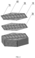
- the present disclosure provides a heat exchanger, as shown in FIG. 1 to FIG. 6 , including a plurality of adjacent sheets 10.
- the plurality of adjacent sheets 10 are stacked to form the heat exchanger.
- the sheets have a hexagonal shape.
- the adjacent sheets 10 extend parallel to one another along the same direction. Two adjacent sheets 10 are connected to each other at least at a part of their peripheral edges or middle portions, and a flow channel for fluid flow is formed between adjacent two sheets 10.
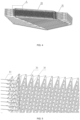
- An upper surface of the sheet 10 is provided with a plurality of raised peak lines 20 that are arranged in parallel and spaced rows and raised upward.
- a lower surface of the sheet 10 is provided with a plurality of raised contour lines 30 that are arranged in parallel and spaced rows and raised downward.
- the raised peak lines 20 and the raised contour lines 30 arranged in rows are both connected by continuous peaks and valleys. Between adjacent two sheets 10, a peak of the raised contour line 30 is located between two valleys of the raised peak line 20, and the peak of the raised contour line 30 and the two valleys of the raised peak line 20 are staggered.
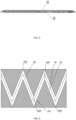
- the peaks 30A of the raised contour lines 30 extend downward to the valleys 20B of the raised peak lines 20, and the peaks 20A of the raised peak lines 20 extend upward to the valleys 30B of the raised contour lines 30.
- Two sides of the peaks 30A of the raised contour lines 30 and two sides of the valleys 20B of the raised peak lines 20 form a two-side gap.
- the fluid flows along a bottom of the valleys 30B of the raised contour lines 30, a bottom of the valleys of the raised peak lines 20, and the two-side gap.
- a first flow channel 40 and a second flow channel 50 are formed by the paths between the peaks and valleys.
- the first flow channel 40 and second flow channel 50 are bypass.
- the fluid flows through the first flow channel 40 along a first direction and a second direction, and the fluid flows through the second flow channel 50 along the first direction and a third direction.
- a convection is formed by the fluid flowing through the first flow channel 40 and the second flow channel 50.
- the first direction is arranged at an angle with respect to the second direction and the third direction.
- the second direction and the third direction are parallel and opposite to each other.
- the first direction is a horizontal direction
- the second direction and the third direction are perpendicular to a paper surface.
- the second direction is perpendicular to the paper surface inward
- the third direction is perpendicular to the paper surface outward.
- the first direction is the horizontal direction, including a horizontal meandering-to-left direction and a horizontal meandering-to-right direction.
- the second direction is a direction shown as ⁇ in the figure, representing the direction perpendicular to the paper surface inward.
- the third direction is a direction shown as ⁇ in the figure, representing the direction perpendicular to the paper surface inward.
- the fluid flows in the first flow channel along a first direction A, the first direction A being the horizontal meandering-to-right direction; and the fluid flows in the second flow channel along a first direction B, the first direction B being the horizontal meandering-to-left direction.
- the first direction A is opposite to the first direction B, so that at least two convections are formed as the fluid passes through the first flow channel and the second flow channel.
- At least two airflows pass through the middles of the sheets during a heat exchange process, which realizes convective heat transfer and mass transfer.
- a first airflow flows through the first flow channel in the second direction
- a second airflow flows through the second flow channel in the third direction.
- the second direction and the third direction are parallel and opposite, so as to form a convection in the direction perpendicular to the paper surface.
- the first airflow and the second airflow also meander forward through the gaps formed between the raised contour lines and the raised peak lines.
- the first airflow meanders forward in the first flow channel along the first direction A
- the second air flow meanders forward in the second flow channel along the first direction B.
- the first direction A and the first direction B are opposite, so as to form another convection in the horizontal direction.
- a trajectory formed by the fluid flowing along the first direction is a curve.
- the curve has alternating peaks and valleys.
- the airflow meanders forward through the gaps formed between the raised contour lines 30 and the raised peak lines 20.
- the trajectory formed by the airflow flowing forward may be in many shapes, including but not limited to, shapes of a sine wave and a triangle wave.
- the trajectory formed by the fluid flowing along the second direction or the third direction is a straight line.
- the second direction and the third direction are parallel and opposite to each other, which is advantageous for forming the convection in the first flow channel 40 and the second flow channel 50.
- a horizontal angle between the first direction and the second direction, and between the first direction and the third direction is ⁇ . ⁇ is ranged from 30° to 90°.
- the trajectory formed by the fluid flowing along the first direction is a triangle wave.
- the triangle wave has alternating triangular peaks and triangular valleys.
- the trajectory formed by the fluid flowing along the first direction satisfies a sawtooth function.
- the peaks 20A of the raised peak lines 20, the valleys 20B of the raised peak lines 20, the peaks 30A of the raised contour lines 30, and the valleys 30B of the raised contour lines 30 are all at an included angle.
- the included angle is preferably an acute angle.
- the trajectory formed by the fluid flowing along the first direction is the triangle wave, which increases a heat exchange area between the fluid and the flow channels, and in addition, reduces the airflow velocity as well as reduces a resistance of the airflow passing through the flow channels.
- the airflow velocity distribution is more uniform, thereby improving heat exchange efficiency.
- the peak 30A of the raised contour line 30 extends into the valley 20B between two raised peak lines 20, and the peak 20A of the raised peak line 20 extends into the valley 30B between two raised contour lines 30.
- the raised contour line 30 and the raised peak line 20 are parallel, and have the same slope in the same length direction.
- a peak top of the raised contour line 30 is located on a center line of the valley between two raised peak lines 20, and a peak top of the raised peak line 20 is located on a center line of the valley between two raised contour lines 30.
- the trajectory formed by the fluid flowing along the first direction is approximately the triangle wave.
- the peaks 20A of the raised peak lines 20, the valleys 20B of the raised peak lines 20, the peaks 30A of the raised contour lines 30, and the valleys 30B of the raised contour lines 30 each are provided with a bending transition section.
- the angles formed by the peaks 20A of the raised peak lines 20, the valleys 20B of the raised peak lines 20, the peaks 30A of the raised contour lines 30, and the valleys 30B of the raised contour lines 30 each are provided with, but limited to, a rounded transition.
- the present disclosure facilitates industrial implementation by providing the bending transition or the rounded transition.
- the sheets may have various shapes, which preferably have a hexagonal shape.
- the sheets may also have, but not limited to, a square shape, a circular shape, an oval shape, an octagonal shape, a diamond shape, etc.
- the plurality of sheets are stacked and connected adjacently to form the heat exchanger.
- the plurality of sheets are stacked to form the first flow channels and the second flow channels that are alternated with each other.
- the flow channels are formed between the adjacent sheets. Specifically, a plurality of flow channels are formed between the raised peak lines 20 arranged in rows and the raised contour lines 30 arranged in rows, and the fluid (airflow) flows through the flow channels formed between the raised peak lines 20 and the raised contour lines 30.
- An upper sheet and a lower sheet are arranged in staggered and parallel fashion. After being stacked, the raised contour lines 30 of the upper sheet are staggered with respect to the raised peak lines 20 of the lower sheet.
- the peaks 20A of the raised peak lines 20 extend upward into the valleys 30B of the raised contour lines 30.
- the two sides of the peaks 30A of the raised contour lines 30 and the two sides of the valleys 20B of the raised peak lines 20 form the two-side gap.
- the fluid flows along the bottom of the valleys 30B of the raised contour lines 30, the bottom of the valleys 20B of the peak lines 20, and the two-side gap, which greatly enhances the heat exchange area of the fluid, thereby improving the heat exchange efficiency.
- the present disclosure by allowing the plurality of airflows to pass through the middle sheets, achieves the convection heat transfer and mass transfer.
- the plurality of airflows flow through the first flow channel and the second flow channel, so as to equalize the airflow velocity distribution, as well as reduce the airflow velocity and reduce the resistance of the airflow passing through the flow channels, thereby improving the heat exchange efficiency.
- d is preferably ranged from 0.5 mm to 5 mm, which may specifically be, but not limited to, 0.5 mm, 1 mm, 2 mm, 3 mm, 4 mm, or 5 mm. More preferably, d is ranged from 1 mm to 4 mm. Even more preferably, d is ranged from 1 mm to 3 mm.
- the distance d between the raised contour lines and the raised peak lines may affect a maximum speed of the airflow and a speed change at a flow channel center, further affecting airflow uniformity.
- d may be ranged from 0.5 mm to 5 mm.
- an inlet wind speed is 1 m/s
- the maximum speed of the airflow is less than 2.6 m/s
- the speed change at the flow channel center is less than or equal to 12%, which can provide better airflow uniformity.
- the maximum speed of the airflow gradually decreases. As d increases from 0.5 mm to 1 mm ⁇ 2.5 mm, the maximum speed of the airflow is in a lowest range, and the maximum speed may be decreased by 20% to 30%. As d increases from 1 mm ⁇ 2.5 mm to 4 mm ⁇ 5 mm, the maximum speed of the airflow increases slowly, and in this case the maximum speed is increased by less than 10%. A smaller maximum speed of the airflow indicates better airflow uniformity.
- a distance between two adjacent peaks of the raised contour lines is L.
- L is preferably ranged from 2 mm to 100 mm. More preferably, L is ranged from 3 mm to 50 mm.
- a vertical distance between the peaks of the raised contour lines and the valleys of the raised contour lines is H.
- H satisfies (H*H)/(L*L)>0.75. More preferably, H satisfies 1.25 ⁇ (H*H)/(L*L) ⁇ 6.6.
- the distance L between two adjacent peaks of the raised contour lines and the vertical distance H between the peaks of the raised contour lines and the valleys of the raised contour lines jointly affect heat exchange effect and manufacturability of the sheets.
- (H*H)/(L*L) ⁇ 0.75 high heat dissipation effect may be obtained.
- the value of (H*H)/(L*L) is beyond an appropriate range, namely (H*H)/(L*L)>6.6, a draw down ratio is too large, which increases difficulty and costs in manufacturing the sheets, and also reduces a service life of the sheets.
- An angle of the peaks of the raised contour lines is ⁇ 1, and an angle of the valleys of the raised peak lines is ⁇ 2.
- ⁇ 1 ⁇ 20.5°, and ⁇ 2 ⁇ 20.5° Preferably, 22° ⁇ 1 ⁇ 60°, and 22° ⁇ 2 ⁇ 60°.
- ⁇ 1, ⁇ 2 ⁇ 20.5° the heat exchange area can be ensured to have a large range, so as to obtain a good heat exchange efficiency. If ⁇ 1, ⁇ 2>60°, the draw down ratio is too small, which cannot guarantee the transfer area of the heat exchanger core. If ⁇ 1, ⁇ 2 ⁇ 20.5°, the manufacturing process of the sheets is difficult.
- the peak of the raised contour line extends into the valley between two raised peak lines, and the peak of the raised peak line extends into the valley between two raised contour lines.
- An extension length is preferably a quarter to two-thirds of a depth of the valley, which may specifically be, but not limited to, one-quarter, one-third, one-half, and two-thirds. This can ensure the exchange area of the heat exchanger core and improve the uniformity of the fluid velocity distribution.
- the distance d between the raised contour lines and the raised peak lines, the distance L between two adjacent peaks of the raised contour lines, the vertical distance H between the peaks of the raised contour lines and the valleys of the raised contour lines, the angle of the peaks of the raised contour lines ⁇ 1, and the angle of the valleys of the raised peak lines ⁇ 2 are used to jointly affect the uniformity of the airflow flow, the heat exchange area, and the uniformity of the velocity distribution of the flow field , thereby obtaining best heat exchange efficiency.
- the sheets are provided with a plurality of raised guiding strips 60 on two sides of the raised peak lines 20 arranged in rows. Inner ends of the raised guiding strips 60 are joined to ends of the raised peak lines 20. Outer edges of the sheets that are located at outer ends of the raised guiding strips 60 are provided with openings, and the remaining outer edges of the sheets are provided with ribs 70.
- the arrangement of the raised guiding strips 60 can change the airflow path, so that the airflow path can be flexibly changed, and can also change the airflow velocity, so as to elongate the heat transfer time, thereby improving the heat exchange efficiency.
- the raised guiding strips 60 are arranged at an included angle ⁇ with the second direction or the third direction, so as to allow the fluid to flow through the first flow channel along the first direction, and along the second direction or the third direction.
- ⁇ Preferably, 0° ⁇ 90°. More preferably, 30° ⁇ 60°.
- the raised guiding strips of adjacent sheets are arranged at an included angle ⁇ .
- ⁇ Preferably, 0° ⁇ 180°. More preferably, 30° ⁇ 150°.
- the sheets each have a microporous structure that is spread over the raised peak lines and the raised contour lines.
- the microporous structure facilitates permeation of water molecules, and thus realizes humidity exchange of the heat exchanger.
- the sheets are provided with a plurality of micropores with a pore diameter of 0.01 ⁇ m to 0.3 ⁇ m. More preferably, the pore diameter of the micropores is ranged from 0.02 ⁇ m to 0.15 ⁇ m. Even more preferably, the pore diameter of the micropores is ranged from 0.05 ⁇ m to 0.1 ⁇ m.
- the micropores form channels through which water molecules pass, so as to allow water molecules to enter and exit the first flow channel.
- water vapor contents of the airflows in the first flow channel and the second flow channel are not the same, which forms a water vapor concentration difference.
- the water vapor concentration difference provides a driving force for diffusion of water molecules, so as to allow the water molecules to move through the micropores from a region of low concentration. In this way, the exchange of the water vapor between the first flow channel and the second flow channel is realized, which is conducive to the uniformity of heat exchange.
- the sheets each are provided with at least one layer of polymer composite coating, which has selective permeability to water molecules. Due to having a temperature exchange function and a humidity exchange function, the polymer composite coating can exchange sensible heat and latent heat at the same time, without allowing other gas molecules to pass through. This ensures tightness of the heat exchanger core, so as to avoid mixing of ventilation air and exhaust air. Thus, the polymer composite coating is suitable for the ventilation system.
- the polymer composite coating may include one or more of polyoxyethylene, polystyrene, polycarbonate, polymethyl methacrylate, polyacrylic acid, polyether polyamide, aliphatic polyurethane, sulfonated styrene, sulfonated polyacrylic acid, and sulfonated polyether ether ketone.
- a heat exchanger includes a plurality of adjacent sheets.
- the adjacent sheets extend parallel to one another along the same direction.
- the adjacent sheets are connected to one another at least at their peripheral edges or middle portions.
- Flow channels for fluid flow are formed between the adjacent sheets.
- An upper surface of each sheet is provided with a plurality of raised peak lines that are arranged in parallel and spaced rows and raised upward, and a lower surface of each sheet is provided with a plurality of raised contour lines that are arranged in parallel and spaced rows and raised downward.
- the raised peak lines and the raised contour lines arranged in rows are both connected by continuous peaks and valleys.
- the peaks of the raised contour lines are located between two valleys of the raised peak lines, and the peaks of the raised contour lines and the two valleys of the raised peak lines are staggered.
- a distance between the raised contour lines and the raised peak lines is d
- a distance between two adjacent peaks of the raised contour lines is L
- a vertical distance between the peaks of the raised contour lines and the valleys of the raised contour lines is H
- an angle of the peaks of the raised contour lines is ⁇ 1
- an angle of the valleys of the raised peak lines is ⁇ 2.
- the peaks of the raised contour lines are located between two valleys of the raised peak lines, and the peaks of the raised contour lines and the two valleys of the raised peak lines are staggered, so as to form a first flow channel and a second flow channel. Fluid flows through the first flow channel along a first direction A and a second direction, and fluid flows through the second flow channel along a first direction B and a third direction. A convection is formed as the fluid passes through the first flow channel and the second flow channel.
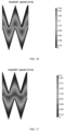
- Sizes of heat exchangers as shown in embodiments 1 to 5 are set according to chart 1.
- Embodiment 1 Embodiment 2 Embodiment 3 Embodiment 4 Embodiment 5 d 1mm 2mm 3mm 4mm 6mm L 3mm 5mm 8mm 10mm 15mm H 3.5 mm 7 mm 10mm 17mm 25 mm ⁇ 1 46.4° 39.3° 43.6° 32.8° 33.4° ⁇ 2 22° 25° 30° 40° 35°
- the heat exchangers in the embodiments 1 to 3 have very uniform fluid velocity distributions.
- the heat exchanger in the embodiment 4 has a relatively uniform fluid velocity distribution.
- the heat exchanger in the embodiment 5 has a less uniform fluid velocity distribution, which satisfies basic requirement.
- the heat exchangers as shown in embodiments 1 to 5 are subjected to exchange efficiency detection, experimental results of which are shown in chart 2.
- the experimental results in chart 2 are based on the following experimental conditions: an outdoor temperature 35°C, an outdoor humidity 28°C, an indoor temperature 27°C, an indoor humidity 19.5°C, an air velocity 1m/s, and a projected heat exchange area of 20 square meters.
- an experimental instrument used in the above experiment is an energy recovery enthalpy difference chamber, and an experimental method refers to the standard "GBIT 21087-2020", energy recovery ventilators for outdoor air handling.
- the above humidity refers to a dew point temperature, which represents the temperature at which the air is cooled to saturation with constant water vapor content and air pressure, and is measured by a psychrometer.
Landscapes
- Engineering & Computer Science (AREA)
- Mechanical Engineering (AREA)
- General Engineering & Computer Science (AREA)
- Physics & Mathematics (AREA)
- Thermal Sciences (AREA)
- Chemical & Material Sciences (AREA)
- Combustion & Propulsion (AREA)
- Heat-Exchange Devices With Radiators And Conduit Assemblies (AREA)
Claims (12)
- Wärmetauscher, aufweisend: mehrere benachbarte Platten (10),wobei sich die benachbarten Platten (10) parallel zueinander entlang derselben Richtung erstrecken;wobei die benachbarten Platten (10) mindestens an einem Teil ihrer Umfangsränder oder mittleren Abschnitte miteinander verbunden sind und zwischen den benachbarten Platten (10) Strömungskanäle für einen Fluidstrom ausgebildet sind;wobei eine obere Oberfläche jeder Platte (10) mit mehreren erhabenen Spitzenlinien (20) versehen ist, die in parallelen und beabstandeten Reihen angeordnet und nach oben erhaben sind, und eine untere Oberfläche jeder Platte (10) mit mehreren erhabenen Konturlinien (30) versehen ist, die in parallelen und beabstandeten Reihen angeordnet und nach unten erhaben sind, wobei die erhabenen Spitzenlinien (20) und die erhabenen Konturlinien (30), die in Reihen angeordnet sind, beide durch kontinuierliche Spitzen und Täler verbunden sind;wobei zwischen benachbarten drei Platten (10) die Spitzen (30A) der erhabenen Konturlinien (30) zwischen zwei Tälern (20B) der erhabenen Spitzenlinien (20) angeordnet sind und die Spitzen (30A) der erhabenen Konturlinien (30) und die zwei Täler (20B) der erhabenen Spitzenlinien (20) versetzt angeordnet sind, um einen ersten Strömungskanal (40) und einen zweiten Strömungskanal (50) zu bilden;wobei Fluid durch den ersten Strömungskanal (40) entlang einer ersten Richtung und einer zweiten Richtung strömt und Fluid durch den zweiten Strömungskanal (50) entlang der ersten Richtung und einer dritten Richtung strömt, um durch das Fluid, das durch den ersten Strömungskanal (40) und den zweiten Strömungskanal (50) strömt, Konvektion zu schaffen; unddie erste Richtung in einem Winkel in Bezug auf die zweite Richtung und die dritte Richtung angeordnet ist und die zweite Richtung und die dritte Richtung parallel zueinander und einander entgegengesetzt sind,dadurch gekennzeichnet, dasseine Trajektorie, die durch das Fluid gebildet wird, das entlang der ersten Richtung strömt, eine Kurve ist, wobei die Kurve abwechselnde Spitzen und Täler aufweist;eine Trajektorie, die durch das Fluid gebildet wird, das entlang der zweiten Richtung oder der dritten Richtung strömt, eine Gerade ist, wobei die zweite Richtung und die dritte Richtung parallel zueinander und einander entgegengesetzt sind; undein horizontaler Winkel zwischen der ersten Richtung und der zweiten Richtung und zwischen der ersten Richtung und der dritten Richtung α ist und α im Bereich von 30° bis 90° liegt.
- Wärmetauscher nach Anspruch 1, wobei das Fluid durch den ersten Strömungskanal entlang einer ersten Richtung A strömt und das Fluid durch den zweiten Strömungskanal entlang einer ersten Richtung B strömt, die erste Richtung A der ersten Richtung B entgegengesetzt ist und durch das Fluid, das durch den ersten Strömungskanal (40) und den zweiten Strömungskanal (50) strömt, mindestens zwei Konvektionen geschaffen werden.
- Wärmetauscher nach Anspruch 1, wobei die Trajektorie, die durch das entlang der ersten Richtung strömende Fluid gebildet wird, eine Dreieckswelle ist, wobei die Dreieckswelle abwechselnde dreieckige Spitzen und dreieckige Täler aufweist; und
die erste Richtung im rechten Winkel zu der zweiten Richtung und der dritten Richtung verläuft. - Wärmetauscher nach Anspruch 1, wobei sich die Spitzen (30A) der erhabenen Konturlinien (30) jeweils in die Täler (20B) zwischen zwei erhabenen Spitzenlinien (20) erstrecken, die Spitzen (20A) der erhabenen Spitzenlinien (20) sich jeweils in die Täler (30B) zwischen zwei erhabenen Konturlinien (30) erstrecken und die erhabenen Konturlinien (30) zu den erhabenen Spitzenlinien (20) parallel verlaufen.
- Wärmetauscher nach Anspruch 4, wobei ein Abstand zwischen den erhabenen Konturlinien (30) und den erhabenen Spitzenlinien (20) d ist und d im Bereich von 0,5 mm bis 5 mm liegt;ein Abstand zwischen zwei benachbarten Spitzen (30A) der erhabenen Konturlinien (30) L ist und L im Bereich von 2 mm bis 100 mm liegt;ein vertikaler Abstand zwischen den Spitzen (30A) der erhabenen Konturlinien (30) und den Tälern (30B) der erhabenen Konturlinien (30) H ist und H (H*H)/(L*L)≥0,75 erfüllt; undein Winkel der Spitzen (30A) der erhabenen Konturlinien (30) δ1 ist und ein Winkel der Täler (20B) der erhabenen Spitzenlinien (20) δ2 ist, δ1≥20,5° und δ2≥20,5°.
- Wärmetauscher nach Anspruch 5, wobei d im Bereich von 1 mm bis 3 mm liegt, L im Bereich von 3 mm bis 50 mm liegt, H 1,25≤(H*H)/(L*L)≤6,6 erfüllt, 22°≤δ1≤60° und 22°≤δ2≤60°.
- Wärmetauscher nach Anspruch 1, wobei sich die Spitzen (30A) der erhabenen Konturlinien (30) jeweils in die Täler (20B) zwischen zwei erhabenen Spitzenlinien (20) erstrecken, die Spitzen (20A) der erhabenen Spitzenlinien (20) sich jeweils in die Täler (30B) zwischen zwei erhabenen Konturlinien (30) erstrecken und eine Erstreckungslänge ein Viertel bis zwei Drittel einer Tiefe der Täler beträgt; und
Spitzenenden der erhabenen Konturlinien (30) jeweils auf Mittellinien der Täler (20B) zwischen zwei erhabenen Spitzenlinien (20) angeordnet sind und Spitzenenden der erhabenen Spitzenlinien (20) jeweils auf Mittellinien der Täler (30B) zwischen zwei erhabenen Konturlinien (30) angeordnet sind. - Wärmetauscher nach Anspruch 1, wobei die Platten mit mehreren erhabenen Leitlamellen (60) auf zwei Seiten der erhabenen Spitzenlinien (20), die in Reihen angeordnet sind, versehen sind; innere Enden der erhabenen Leitlamellen (60) mit Enden der erhabenen Spitzenlinien (20) verbunden sind, äußere Ränder der Platten, die an äußeren Enden der erhabenen Leitlamellen (60) angeordnet sind, mit Öffnungen versehen sind und die übrigen äußeren Ränder der Platten mit Rippen (70) versehen sind.
- Wärmetauscher nach Anspruch 8, wobei die erhabenen Leitlamellen (60) in einem mit der zweiten Richtung oder der dritten Richtung eingeschlossenen Winkel β angeordnet sind und 0°<β<90°.
- Wärmetauscher nach Anspruch 8, wobei die erhabenen Leitlamellen (60) der benachbarten Platten in einem eingeschlossenen Winkel γ angeordnet sind und 0°<γ<180°.
- Wärmetauscher nach Anspruch 1, wobei die Platten jeweils eine mikroporöse Struktur aufweisen und ein Porendurchmesser einer Mikropore im Bereich von 0,01 µm bis 0,3 µm liegt.
- Wärmetauscher nach Anspruch 1, wobei die Platten jeweils mit mindestens einer Schicht aus Polymerkompositbeschichtung versehen sind, wobei die Polymerkompositbeschichtung selektive Durchlässigkeit für Wassermoleküle aufweist.
Applications Claiming Priority (2)
| Application Number | Priority Date | Filing Date | Title |
|---|---|---|---|
| CN202011582385.9A CN112595153A (zh) | 2020-12-28 | 2020-12-28 | 一种热交换体 |
| CN202111438607 | 2021-11-29 |
Publications (3)
| Publication Number | Publication Date |
|---|---|
| EP4019879A1 EP4019879A1 (de) | 2022-06-29 |
| EP4019879C0 EP4019879C0 (de) | 2024-08-28 |
| EP4019879B1 true EP4019879B1 (de) | 2024-08-28 |
Family
ID=79171292
Family Applications (1)
| Application Number | Title | Priority Date | Filing Date |
|---|---|---|---|
| EP21217891.7A Active EP4019879B1 (de) | 2020-12-28 | 2021-12-28 | Wärmetauscher |
Country Status (5)
| Country | Link |
|---|---|
| US (1) | US20220214114A1 (de) |
| EP (1) | EP4019879B1 (de) |
| JP (1) | JP2022104630A (de) |
| KR (1) | KR20220094169A (de) |
| CA (1) | CA3143766C (de) |
Citations (8)
| Publication number | Priority date | Publication date | Assignee | Title |
|---|---|---|---|---|
| JPS63140295A (ja) | 1986-11-30 | 1988-06-11 | Mikio Kususe | 対向流熱交換器 |
| JPH11325780A (ja) | 1998-05-13 | 1999-11-26 | Matsushita Seiko Co Ltd | 熱交換素子 |
| WO2013091099A1 (en) | 2011-12-19 | 2013-06-27 | Dpoint Technologies Inc. | Counter-flow energy recovery ventilator (erv) core |
| WO2013093375A1 (fr) | 2011-12-21 | 2013-06-27 | Elyt 3 | Plaque pour échangeur thermique |
| FR3000189A1 (fr) | 2012-12-21 | 2014-06-27 | Elyt 3 | Plaque pour echangeur thermique |
| EP2908080A1 (de) | 2014-02-13 | 2015-08-19 | Ekocoil Oy | Wärmetauscherstruktur zur Reduzierung der Akkumulation von Flüssigkeit und Gefrieren |
| RU2585130C1 (ru) | 2014-11-14 | 2016-05-27 | Частное Акционерное Общество "Вентиляционные системы" | Пакет пластинчатого теплообменника |
| WO2018132014A1 (en) | 2017-01-16 | 2018-07-19 | Recair Holding B.V. | Recuperator |
Family Cites Families (11)
| Publication number | Priority date | Publication date | Assignee | Title |
|---|---|---|---|---|
| SE7509633L (sv) * | 1975-02-07 | 1976-08-09 | Terence Peter Nicholson | Anordning vid plattvermevexlare |
| AUPM777294A0 (en) * | 1994-08-30 | 1994-09-22 | William Allen Trusts Pty Ltd | Spaced evaporative wicks within an air cooler |
| JP3577863B2 (ja) * | 1996-09-10 | 2004-10-20 | 三菱電機株式会社 | 対向流型熱交換器 |
| JP3362611B2 (ja) * | 1996-09-12 | 2003-01-07 | 三菱電機株式会社 | 熱交換器および該熱交換器の熱交換部材の製造方法 |
| GB0210434D0 (en) * | 2002-05-08 | 2002-06-12 | Smiths Group Plc | Apparatus |
| US20210010759A1 (en) * | 2012-07-11 | 2021-01-14 | Kraton Polymers Llc | Enhanced-efficiency energy recovery ventilation core |
| FR3024533B1 (fr) * | 2014-07-31 | 2016-08-26 | Commissariat Energie Atomique | Echangeur enthalpique ameliore |
| CZ305957B6 (cs) * | 2014-12-23 | 2016-05-18 | 2Vv S.R.O. | Entalpický výměník tepla |
| EP3168561A1 (de) * | 2015-11-11 | 2017-05-17 | Air To Air Sweden AB | Vorrichtung zum austausch von wärme und/oder masseaustausch zwischen fluidströmen |
| EP3276292A1 (de) * | 2016-07-25 | 2018-01-31 | Zehnder Group International AG | Enthalpietauscherelement, enthalpietauscher mit solchen elementen und verfahren zu deren herstellung |
| JP2020038023A (ja) * | 2018-09-03 | 2020-03-12 | 株式会社東芝 | 全熱交換素子用シート、全熱交換素子、全熱交換器、及び水蒸気分離体 |
-
2021
- 2021-12-23 CA CA3143766A patent/CA3143766C/en active Active
- 2021-12-27 US US17/562,954 patent/US20220214114A1/en not_active Abandoned
- 2021-12-28 KR KR1020210189235A patent/KR20220094169A/ko not_active Ceased
- 2021-12-28 JP JP2021214789A patent/JP2022104630A/ja active Pending
- 2021-12-28 EP EP21217891.7A patent/EP4019879B1/de active Active
Patent Citations (9)
| Publication number | Priority date | Publication date | Assignee | Title |
|---|---|---|---|---|
| JPS63140295A (ja) | 1986-11-30 | 1988-06-11 | Mikio Kususe | 対向流熱交換器 |
| JPH11325780A (ja) | 1998-05-13 | 1999-11-26 | Matsushita Seiko Co Ltd | 熱交換素子 |
| WO2013091099A1 (en) | 2011-12-19 | 2013-06-27 | Dpoint Technologies Inc. | Counter-flow energy recovery ventilator (erv) core |
| WO2013093375A1 (fr) | 2011-12-21 | 2013-06-27 | Elyt 3 | Plaque pour échangeur thermique |
| FR3000189A1 (fr) | 2012-12-21 | 2014-06-27 | Elyt 3 | Plaque pour echangeur thermique |
| EP2908080A1 (de) | 2014-02-13 | 2015-08-19 | Ekocoil Oy | Wärmetauscherstruktur zur Reduzierung der Akkumulation von Flüssigkeit und Gefrieren |
| RU2585130C1 (ru) | 2014-11-14 | 2016-05-27 | Частное Акционерное Общество "Вентиляционные системы" | Пакет пластинчатого теплообменника |
| PL230126B1 (pl) | 2014-11-14 | 2018-09-28 | Pryvatne Aktsionerne Tovarystvo Ventylatsijni Systemy | Zestaw płytkowego wymiennika ciepła |
| WO2018132014A1 (en) | 2017-01-16 | 2018-07-19 | Recair Holding B.V. | Recuperator |
Non-Patent Citations (2)
| Title |
|---|
| ANONYMOUS: "Direction (geometry)", WIKIPEDIA, 17 January 2025 (2025-01-17), XP093276337, Retrieved from the Internet <URL:https://en.wikipedia.org/w/index.php?title=Direction_(geometry)&oldid=1270028539> |
| ANONYMOUS: "Fluiddynamische Grenzschicht", WIKIPEDIA, 22 March 2025 (2025-03-22), XP093276340, Retrieved from the Internet <URL:https://de.wikipedia.org/w/index.php?title=Fluiddynamische_Grenzschicht&oldid=254422866> |
Also Published As
| Publication number | Publication date |
|---|---|
| CA3143766A1 (en) | 2022-06-28 |
| EP4019879A1 (de) | 2022-06-29 |
| KR20220094169A (ko) | 2022-07-05 |
| EP4019879C0 (de) | 2024-08-28 |
| CA3143766C (en) | 2025-09-09 |
| US20220214114A1 (en) | 2022-07-07 |
| JP2022104630A (ja) | 2022-07-08 |
Similar Documents
| Publication | Publication Date | Title |
|---|---|---|
| US11906199B2 (en) | Enthalpy exchanger | |
| EP2791608B1 (de) | Verdampfungskühler, adiabatischer Kühler oder Befeuchtungseinheit und zugehöriges Herstellungsverfahren | |
| US20110209858A1 (en) | Indirect Evaporative Cooling Apparatus | |
| US9347675B2 (en) | Architectural heat and moisture exchange | |
| KR20140001200A (ko) | 열전달 및 수분전달 기능이 개선된 2중 공기흐름 교환기 | |
| CA2423472A1 (en) | Method and plate apparatus for dew point evaporative cooler | |
| US20120012290A1 (en) | Architectural heat and moisture exchange | |
| CN107606977A (zh) | 热交换单体、热交换机芯和全热交换器 | |
| CN103175293B (zh) | 新风换气机用平板全热换热芯体 | |
| CN114264173A (zh) | 一种热交换体 | |
| EP4019879B1 (de) | Wärmetauscher | |
| CN115076816A (zh) | 湿帘结构 | |
| JP2010151344A (ja) | 全熱交換器 | |
| KR100783616B1 (ko) | 배기열 회수용 열교환기 | |
| EP1453623B1 (de) | Gemusterte platten zur herstellung von wärmetauschern und anderen konstruktionen | |
| CN210602055U (zh) | 甲醛过滤网和空气处理装置 | |
| JP2008070070A (ja) | 全熱交換器 | |
| CN203203214U (zh) | 一种新风换气机用导板膜式全热换热芯体 | |
| KR20080084569A (ko) | 전열 교환기 및 그 제조법 | |
| CN217979100U (zh) | 湿帘结构及具有其的制冷结构 | |
| JP4021048B2 (ja) | 熱交換素子 | |
| CN210373867U (zh) | 甲醛过滤网和空气处理装置 | |
| JPS6213988A (ja) | 熱交換器 |
Legal Events
| Date | Code | Title | Description |
|---|---|---|---|
| PUAI | Public reference made under article 153(3) epc to a published international application that has entered the european phase |
Free format text: ORIGINAL CODE: 0009012 |
|
| STAA | Information on the status of an ep patent application or granted ep patent |
Free format text: STATUS: THE APPLICATION HAS BEEN PUBLISHED |
|
| AK | Designated contracting states |
Kind code of ref document: A1 Designated state(s): AL AT BE BG CH CY CZ DE DK EE ES FI FR GB GR HR HU IE IS IT LI LT LU LV MC MK MT NL NO PL PT RO RS SE SI SK SM TR |
|
| STAA | Information on the status of an ep patent application or granted ep patent |
Free format text: STATUS: REQUEST FOR EXAMINATION WAS MADE |
|
| 17P | Request for examination filed |
Effective date: 20221208 |
|
| RBV | Designated contracting states (corrected) |
Designated state(s): AL AT BE BG CH CY CZ DE DK EE ES FI FR GB GR HR HU IE IS IT LI LT LU LV MC MK MT NL NO PL PT RO RS SE SI SK SM TR |
|
| GRAP | Despatch of communication of intention to grant a patent |
Free format text: ORIGINAL CODE: EPIDOSNIGR1 |
|
| STAA | Information on the status of an ep patent application or granted ep patent |
Free format text: STATUS: GRANT OF PATENT IS INTENDED |
|
| INTG | Intention to grant announced |
Effective date: 20240507 |
|
| GRAS | Grant fee paid |
Free format text: ORIGINAL CODE: EPIDOSNIGR3 |
|
| GRAA | (expected) grant |
Free format text: ORIGINAL CODE: 0009210 |
|
| STAA | Information on the status of an ep patent application or granted ep patent |
Free format text: STATUS: THE PATENT HAS BEEN GRANTED |
|
| AK | Designated contracting states |
Kind code of ref document: B1 Designated state(s): AL AT BE BG CH CY CZ DE DK EE ES FI FR GB GR HR HU IE IS IT LI LT LU LV MC MK MT NL NO PL PT RO RS SE SI SK SM TR |
|
| REG | Reference to a national code |
Ref country code: CH Ref legal event code: EP |
|
| REG | Reference to a national code |
Ref country code: DE Ref legal event code: R096 Ref document number: 602021017886 Country of ref document: DE |
|
| REG | Reference to a national code |
Ref country code: IE Ref legal event code: FG4D |
|
| U01 | Request for unitary effect filed |
Effective date: 20240926 |
|
| U07 | Unitary effect registered |
Designated state(s): AT BE BG DE DK EE FI FR IT LT LU LV MT NL PT RO SE SI Effective date: 20241024 |
|
| PG25 | Lapsed in a contracting state [announced via postgrant information from national office to epo] |
Ref country code: NO Free format text: LAPSE BECAUSE OF FAILURE TO SUBMIT A TRANSLATION OF THE DESCRIPTION OR TO PAY THE FEE WITHIN THE PRESCRIBED TIME-LIMIT Effective date: 20241128 |
|
| PG25 | Lapsed in a contracting state [announced via postgrant information from national office to epo] |
Ref country code: PL Free format text: LAPSE BECAUSE OF FAILURE TO SUBMIT A TRANSLATION OF THE DESCRIPTION OR TO PAY THE FEE WITHIN THE PRESCRIBED TIME-LIMIT Effective date: 20240828 Ref country code: GR Free format text: LAPSE BECAUSE OF FAILURE TO SUBMIT A TRANSLATION OF THE DESCRIPTION OR TO PAY THE FEE WITHIN THE PRESCRIBED TIME-LIMIT Effective date: 20241129 |
|
| U20 | Renewal fee for the european patent with unitary effect paid |
Year of fee payment: 4 Effective date: 20241219 |
|
| PG25 | Lapsed in a contracting state [announced via postgrant information from national office to epo] |
Ref country code: IS Free format text: LAPSE BECAUSE OF FAILURE TO SUBMIT A TRANSLATION OF THE DESCRIPTION OR TO PAY THE FEE WITHIN THE PRESCRIBED TIME-LIMIT Effective date: 20241228 |
|
| PG25 | Lapsed in a contracting state [announced via postgrant information from national office to epo] |
Ref country code: HR Free format text: LAPSE BECAUSE OF FAILURE TO SUBMIT A TRANSLATION OF THE DESCRIPTION OR TO PAY THE FEE WITHIN THE PRESCRIBED TIME-LIMIT Effective date: 20240828 |
|
| PG25 | Lapsed in a contracting state [announced via postgrant information from national office to epo] |
Ref country code: RS Free format text: LAPSE BECAUSE OF FAILURE TO SUBMIT A TRANSLATION OF THE DESCRIPTION OR TO PAY THE FEE WITHIN THE PRESCRIBED TIME-LIMIT Effective date: 20241128 Ref country code: ES Free format text: LAPSE BECAUSE OF FAILURE TO SUBMIT A TRANSLATION OF THE DESCRIPTION OR TO PAY THE FEE WITHIN THE PRESCRIBED TIME-LIMIT Effective date: 20240828 |
|
| PG25 | Lapsed in a contracting state [announced via postgrant information from national office to epo] |
Ref country code: RS Free format text: LAPSE BECAUSE OF FAILURE TO SUBMIT A TRANSLATION OF THE DESCRIPTION OR TO PAY THE FEE WITHIN THE PRESCRIBED TIME-LIMIT Effective date: 20241128 Ref country code: PL Free format text: LAPSE BECAUSE OF FAILURE TO SUBMIT A TRANSLATION OF THE DESCRIPTION OR TO PAY THE FEE WITHIN THE PRESCRIBED TIME-LIMIT Effective date: 20240828 Ref country code: NO Free format text: LAPSE BECAUSE OF FAILURE TO SUBMIT A TRANSLATION OF THE DESCRIPTION OR TO PAY THE FEE WITHIN THE PRESCRIBED TIME-LIMIT Effective date: 20241128 Ref country code: IS Free format text: LAPSE BECAUSE OF FAILURE TO SUBMIT A TRANSLATION OF THE DESCRIPTION OR TO PAY THE FEE WITHIN THE PRESCRIBED TIME-LIMIT Effective date: 20241228 Ref country code: HR Free format text: LAPSE BECAUSE OF FAILURE TO SUBMIT A TRANSLATION OF THE DESCRIPTION OR TO PAY THE FEE WITHIN THE PRESCRIBED TIME-LIMIT Effective date: 20240828 Ref country code: GR Free format text: LAPSE BECAUSE OF FAILURE TO SUBMIT A TRANSLATION OF THE DESCRIPTION OR TO PAY THE FEE WITHIN THE PRESCRIBED TIME-LIMIT Effective date: 20241129 Ref country code: ES Free format text: LAPSE BECAUSE OF FAILURE TO SUBMIT A TRANSLATION OF THE DESCRIPTION OR TO PAY THE FEE WITHIN THE PRESCRIBED TIME-LIMIT Effective date: 20240828 |
|
| PG25 | Lapsed in a contracting state [announced via postgrant information from national office to epo] |
Ref country code: SM Free format text: LAPSE BECAUSE OF FAILURE TO SUBMIT A TRANSLATION OF THE DESCRIPTION OR TO PAY THE FEE WITHIN THE PRESCRIBED TIME-LIMIT Effective date: 20240828 |
|
| PG25 | Lapsed in a contracting state [announced via postgrant information from national office to epo] |
Ref country code: CZ Free format text: LAPSE BECAUSE OF FAILURE TO SUBMIT A TRANSLATION OF THE DESCRIPTION OR TO PAY THE FEE WITHIN THE PRESCRIBED TIME-LIMIT Effective date: 20240828 |
|
| PG25 | Lapsed in a contracting state [announced via postgrant information from national office to epo] |
Ref country code: SK Free format text: LAPSE BECAUSE OF FAILURE TO SUBMIT A TRANSLATION OF THE DESCRIPTION OR TO PAY THE FEE WITHIN THE PRESCRIBED TIME-LIMIT Effective date: 20240828 |
|
| PLBI | Opposition filed |
Free format text: ORIGINAL CODE: 0009260 |
|
| 26 | Opposition filed |
Opponent name: KOVINYA, MYKOLA Effective date: 20250505 |
|
| PLAX | Notice of opposition and request to file observation + time limit sent |
Free format text: ORIGINAL CODE: EPIDOSNOBS2 |
|
| PG25 | Lapsed in a contracting state [announced via postgrant information from national office to epo] |
Ref country code: MC Free format text: LAPSE BECAUSE OF FAILURE TO SUBMIT A TRANSLATION OF THE DESCRIPTION OR TO PAY THE FEE WITHIN THE PRESCRIBED TIME-LIMIT Effective date: 20240828 |
|
| REG | Reference to a national code |
Ref country code: CH Ref legal event code: PL |
|
| PG25 | Lapsed in a contracting state [announced via postgrant information from national office to epo] |
Ref country code: CH Free format text: LAPSE BECAUSE OF NON-PAYMENT OF DUE FEES Effective date: 20241231 |
|
| PG25 | Lapsed in a contracting state [announced via postgrant information from national office to epo] |
Ref country code: IE Free format text: LAPSE BECAUSE OF NON-PAYMENT OF DUE FEES Effective date: 20241228 |