EP4019080B1 - Arrays zur abgabe von tumorbehandlungsfeldern (ttfields) mit selektiv adressierbaren unterelementen - Google Patents
Arrays zur abgabe von tumorbehandlungsfeldern (ttfields) mit selektiv adressierbaren unterelementen Download PDFInfo
- Publication number
- EP4019080B1 EP4019080B1 EP22150741.1A EP22150741A EP4019080B1 EP 4019080 B1 EP4019080 B1 EP 4019080B1 EP 22150741 A EP22150741 A EP 22150741A EP 4019080 B1 EP4019080 B1 EP 4019080B1
- Authority
- EP
- European Patent Office
- Prior art keywords
- electrode elements
- temperature
- electrode
- controller
- current
- Prior art date
- Legal status (The legal status is an assumption and is not a legal conclusion. Google has not performed a legal analysis and makes no representation as to the accuracy of the status listed.)
- Active
Links
Images


Classifications
-
- A—HUMAN NECESSITIES
- A61—MEDICAL OR VETERINARY SCIENCE; HYGIENE
- A61N—ELECTROTHERAPY; MAGNETOTHERAPY; RADIATION THERAPY; ULTRASOUND THERAPY
- A61N1/00—Electrotherapy; Circuits therefor
- A61N1/02—Details
- A61N1/04—Electrodes
- A61N1/0404—Electrodes for external use
-
- A—HUMAN NECESSITIES
- A61—MEDICAL OR VETERINARY SCIENCE; HYGIENE
- A61N—ELECTROTHERAPY; MAGNETOTHERAPY; RADIATION THERAPY; ULTRASOUND THERAPY
- A61N1/00—Electrotherapy; Circuits therefor
- A61N1/02—Details
- A61N1/04—Electrodes
- A61N1/0404—Electrodes for external use
- A61N1/0408—Use-related aspects
- A61N1/0456—Specially adapted for transcutaneous electrical nerve stimulation [TENS]
-
- A—HUMAN NECESSITIES
- A61—MEDICAL OR VETERINARY SCIENCE; HYGIENE
- A61N—ELECTROTHERAPY; MAGNETOTHERAPY; RADIATION THERAPY; ULTRASOUND THERAPY
- A61N1/00—Electrotherapy; Circuits therefor
- A61N1/02—Details
- A61N1/04—Electrodes
- A61N1/0404—Electrodes for external use
- A61N1/0472—Structure-related aspects
- A61N1/0476—Array electrodes (including any electrode arrangement with more than one electrode for at least one of the polarities)
-
- A—HUMAN NECESSITIES
- A61—MEDICAL OR VETERINARY SCIENCE; HYGIENE
- A61N—ELECTROTHERAPY; MAGNETOTHERAPY; RADIATION THERAPY; ULTRASOUND THERAPY
- A61N1/00—Electrotherapy; Circuits therefor
- A61N1/02—Details
- A61N1/04—Electrodes
- A61N1/05—Electrodes for implantation or insertion into the body, e.g. heart electrode
- A61N1/0526—Head electrodes
- A61N1/0529—Electrodes for brain stimulation
-
- A—HUMAN NECESSITIES
- A61—MEDICAL OR VETERINARY SCIENCE; HYGIENE
- A61N—ELECTROTHERAPY; MAGNETOTHERAPY; RADIATION THERAPY; ULTRASOUND THERAPY
- A61N1/00—Electrotherapy; Circuits therefor
- A61N1/02—Details
- A61N1/08—Arrangements or circuits for monitoring, protecting, controlling or indicating
-
- A—HUMAN NECESSITIES
- A61—MEDICAL OR VETERINARY SCIENCE; HYGIENE
- A61N—ELECTROTHERAPY; MAGNETOTHERAPY; RADIATION THERAPY; ULTRASOUND THERAPY
- A61N1/00—Electrotherapy; Circuits therefor
- A61N1/18—Applying electric currents by contact electrodes
- A61N1/32—Applying electric currents by contact electrodes alternating or intermittent currents
- A61N1/36—Applying electric currents by contact electrodes alternating or intermittent currents for stimulation
- A61N1/36002—Cancer treatment, e.g. tumour
-
- A—HUMAN NECESSITIES
- A61—MEDICAL OR VETERINARY SCIENCE; HYGIENE
- A61N—ELECTROTHERAPY; MAGNETOTHERAPY; RADIATION THERAPY; ULTRASOUND THERAPY
- A61N1/00—Electrotherapy; Circuits therefor
- A61N1/18—Applying electric currents by contact electrodes
- A61N1/32—Applying electric currents by contact electrodes alternating or intermittent currents
- A61N1/36—Applying electric currents by contact electrodes alternating or intermittent currents for stimulation
- A61N1/36014—External stimulators, e.g. with patch electrodes
- A61N1/36025—External stimulators, e.g. with patch electrodes for treating a mental or cerebral condition
-
- A—HUMAN NECESSITIES
- A61—MEDICAL OR VETERINARY SCIENCE; HYGIENE
- A61N—ELECTROTHERAPY; MAGNETOTHERAPY; RADIATION THERAPY; ULTRASOUND THERAPY
- A61N1/00—Electrotherapy; Circuits therefor
- A61N1/18—Applying electric currents by contact electrodes
- A61N1/32—Applying electric currents by contact electrodes alternating or intermittent currents
- A61N1/36—Applying electric currents by contact electrodes alternating or intermittent currents for stimulation
- A61N1/36014—External stimulators, e.g. with patch electrodes
- A61N1/3603—Control systems
-
- A—HUMAN NECESSITIES
- A61—MEDICAL OR VETERINARY SCIENCE; HYGIENE
- A61N—ELECTROTHERAPY; MAGNETOTHERAPY; RADIATION THERAPY; ULTRASOUND THERAPY
- A61N1/00—Electrotherapy; Circuits therefor
- A61N1/40—Applying electric fields by inductive or capacitive coupling ; Applying radio-frequency signals
Definitions
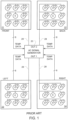
- FIG. 1 is a schematic representation of the prior art Optune ® system for delivering TTFields.
- the TTFields are delivered to patients via four transducer arrays 21-24 that are placed on the patient's skin in close proximity to a tumor (e.g., as depicted in FIGS. 2A-2D for a person with glioblastoma).
- the transducer arrays 21-24 are arranged in two pairs, and each transducer array is connected via a multi-wire cable to an AC signal generator 20.
- the AC signal generator (a) sends an AC current through one pair of arrays 21, 22 during a first period of time, which induces an electric field with a first direction through the tumor; then (b) sends an AC current through the other pair of arrays 23, 24 during a second period of time, which induces an electric field with a second direction through the tumor; then repeats steps (a) and (b) for the duration of the treatment.
- Each transducer array 21-24 is configured as a set of capacitively coupled electrode elements E (e.g., a set of 9 electrode elements, each of which is about 2 cm in diameter) that are interconnected via flex wires.
- Each electrode element includes a ceramic disk that is sandwiched between a layer of an electrically conductive medical gel and an adhesive tape. When placing the arrays on the patient, the medical gel adheres to the contours of the patient's skin and ensures good electric contact of the device with the body. The adhesive tape holds the entire array in place on the patient as the patient goes about their daily activities.
- the amplitude of the alternating current that is delivered via the transducer arrays is controlled so that skin temperature (as measured on the skin below the transducer arrays) does not exceed a safety threshold of 41° C.
- the temperature measurements on the patient's skin are obtained using thermistors T placed beneath some of the disks of the transducer arrays.
- each array includes 8 thermistors, with one thermistor positioned beneath a respective disk in the array. (Note that most arrays include more than 8 disks, in which case the temperature measurements are only performed beneath a sub-set of the disks within the array).
- US-A-2009/0076366 discloses an electrode for applying electric fields to a body part of a subject, comprising a plurality of ceramic elements arranged in an array.
- WO-A-2017/141257 discloses a non-invasive electric brain stimulation system, comprising an electrode array which includes a plurality of co-centric or semi-co-centric electrodes.
- US 2018/050200 Al shows another apparatus for applying TTFields with an alternating current (AC) signal generator, a plurality of arrays of electrode elements configured for placement against a subject's body and temperature sensors in the respective arrays.
- AC alternating current
- the embodiments described herein can cut the average current through the single electrode element by 10% by switching the current through that single electrode element on and off with a 90% duty cycle, while leaving the current on full-time for all the remaining electrode elements.
- the switching rate must be sufficiently fast so that the instantaneous temperature at the single electrode element never exceeds 41°, in view of the thermal inertia of the electrode elements.
- a 90% duty cycle could be achieved by switching the current on for 90 ms and switching the current off for 10 ms.
- the period of switching the current on and off is less than 1 s.
- the current through the remaining 9 electrode elements can remain unchanged (i.e., 50 mA per electrode element), and only the current through the single electrode element is reduced to an average of 45 mA.
- the average net total current through the transducer array will then be 495 mA (i.e., 9 ⁇ 50 + 45), which means that significantly more current can be coupled into the person's body without exceeding 41° at any of the electrode elements.
- the system may even be configured to increase the current through the remaining nine electrode elements in order to compensate for the reduction in current through the single electrode element.
- a similar technique i.e. a reduction in the duty cycle from 100% to something less than 100% may be used to prevent the temperature at the second electrode element from exceeding 41°.
- this technique may be used to individually customize the duty cycle at each of the electrode elements in order to maximize the current that flows through each of those electrode elements while keeping the temperature at each of those elements below 41°.
- the system may be configured to proactively set the duty cycle at each of the electrode elements in a given transducer array individually so as to equalize the temperature across all of the electrode elements in the array.
- the system could be configured to individually set the duty cycle at each electrode element so as to maintain a temperature that hovers around 40.5° at each of the electrode elements.
- the system may be configured to send a request to the AC voltage generator to increase or decrease the voltage as required in order to achieve this result.
- This approach can be used to ensure that each and every electrode element will carry the maximum average current possible (without exceeding 41°), which will provide an increased field strength in the tumor and a corresponding improvement in the treatment.
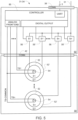
- FIG. 3 depicts a first design that periodically switches the current on and off for each individual electrode element that begins to approach 41 °.
- the AC signal generator 30 has two outputs (OUT1 and OUT2), each of which has two terminals.
- the AC signal generator 30 generates an AC signal (e.g. a 200 kHz sine wave) between the two terminals of each of those outputs in an alternating sequence (e.g., activating OUT1 for 1 sec., then activating OUT2 for one sec., in an alternating sequence).
- a pair of conductors 51 are connected to the two terminals of OUT1, and each of those conductors 51 goes to a respective one of the left and right transducer assemblies 31, 32.
- a second pair of conductors 51 are connected to the two terminals of OUT2 and each of those conductors 51 goes to a respective one of the front and back transducer assemblies (not shown).
- the construction and operation of the front and back transducer assemblies is similar to the construction of the left and right transducer assemblies 31, 32 depicted in FIG. 3 .
- Each of the transducer assemblies 31, 32 includes a plurality of electrode elements 52.
- each of these electrode elements 52 is a capacitively coupled electrode element that is similar to the prior art electrode elements used in the Optune ® system.
- an electrically controlled switch (S) 56 is wired in series with each electrode element (E) 52, and all of these S+E combinations 56+52 are wired in parallel.
- Each of the switches 56 is configured to switch on or off independently of other switches based on a state of a respective control input that arrives from the digital output of the respective controller 85.
- each of the capacitively coupled electrode elements 52 is disc-shaped (e.g., with a 2 cm diameter) and has a dielectric layer on one side.
- the transducer assembly 31, 32 holds the electrode elements 52 against the subject's body with the dielectric layer of the electrode elements facing the subject body.
- a layer of hydrogel is disposed between the dielectric layer of the electrode elements and the subject's body when the transducer assembly 31, 32 is placed against the subject's body so it can hold the electrode elements 52 against a subject's body.
- each of the capacitively coupled electrode elements 52 comprises a conductive plate with a flat face, and the dielectric layer is disposed on the flat face of the conductive plate.
- all of the capacitively coupled electrode elements are held in place by a support structure.
- this support structure may comprise a layer of foam.
- the electrical connection to each of the electrode elements 52 comprises a trace on a flex circuit.
- Each of the transducer assemblies 31, 32 also includes a temperature sensor 54 (e.g., a thermistor) positioned at each of the electrode elements 52 so that each temperature sensor 54 can sense the temperature of a respective electrode element 52.
- a temperature sensor 54 e.g., a thermistor
- Each of the temperature sensors 54 generates a signal indicative of the temperature at (e.g., beneath) the respective electrode element 52.
- the signals from the temperature sensors 54 are provided to the analog front and of the respective controller 85.
- temperature readings may be obtained by routing a known current through each thermistor and measuring the voltage that appears across each thermistor.
- thermistor-based temperature measurements may be implemented using a bidirectional analog multiplexer to select each of the thermistors in turn, with a current source that generates a known current (e.g., 150 ⁇ A) positioned behind the multiplexer, so that the known current will be routed into whichever thermistor is selected by the analog multiplexer at any given instant.
- the known current will cause a voltage to appear across the selected thermistor, and the temperature of the selected thermistor can be determined by measuring this voltage.
- the controller 85 runs a program that selects each of the thermistors in turn and measures the voltage that appears across each of the thermistors (which is indicative of the temperature at the selected thermistor) in turn.
- An example of suitable hardware and procedures that may be used to obtain temperature readings from each of the thermistors is described in US-A-2018/0050200 .
- the controller 85 may be implemented using a single-chip microcontroller or Programmable System on Chip (PSoC) with a built in analog front end and multiplexer. Suitable part numbers for this purpose include the CY8C4124LQI-443. In alternative designs, other microcontrollers may be used with either built-in or discrete analog front ends and multiplexers, as will be apparent to persons skilled in the relevant arts.
- POC Programmable System on Chip
- an alternative approach for interfacing with the thermistors may be used in place of the constant current approach described above.
- a different type of temperature sensor may be used in place of the thermistors described above. Examples include thermocouples, RIDs, and integrated circuit temperature sensors such as the Analog Devices AD590 and the Texas Instruments LM135.
- thermocouples, RIDs, and integrated circuit temperature sensors such as the Analog Devices AD590 and the Texas Instruments LM135.
- the controller 85 is programmed to keep the temperature at all of the electrode elements below a safety threshold (e.g., below 41° C) using intelligence that is built into each transducer assembly 31. This may be accomplished, for example, by programming the controller 85 to start out by setting its digital output so that each of the switches 56 is continuously on (i.e., with a 100% duty cycle). Then, based on signals arriving via the controller 85 analog front end, the controller 85 determines whether the temperature at each of the electrode elements exceeds an upper threshold (e.g. 40° C) that is below the safety threshold. When the controller 85 detects this condition, the controller 85 reduces the duty cycle for the corresponding switch 56 by toggling the corresponding digital output at the desired duty cycle.
- a safety threshold e.g., below 41° C
- the level of reduction in current is determined by the duty cycle. For example, using a 50% duty cycle will cut the current by half; and using a 75% duty cycle will cut the current by 25%.
- the controller 85 in each of the transducer assemblies 31, 32 monitors the temperature at each of the electrode elements 52 in that transducer assembly by inputting signals from each of the temperature sensors 54 via the analog front end of the controller 85. Now assume that the temperature at a given one of the electrode elements 52 in the transducer assembly 31 has risen to 40° C. This condition will be reported to the controller 85 in the transducer assembly 31 via a signal from the corresponding temperature sensor 54. When the controller 85 recognizes that the temperature of the given electrode element 52 has risen to 40° C, the controller 85 will toggle the control signal that goes to the corresponding switch 56 at the desired duty cycle in order to periodically interrupt the current to the given electrode element 52 and maintain a lower average current.
- the controller 85 can send a request to the AC signal generator 30 via the UART in the controller 85. When the AC signal generator 30 receives this request, the AC signal generator 30 will reduce the output current at its corresponding output OUT1.
- the controller 85 can reduce the average current at a given electrode element 52 based on real-time temperature measurements by turning off the current to the given electrode element 52 and waiting until temperature measured using the temperature sensors 54 drops below a second temperature threshold (e.g., below 38° C). Once the temperature drops below this second temperature threshold, the controller 85 can restore the current to the given electrode element 52. This may be accomplished, for example, by controlling the state of the control input to the switch 56 that was previously turned off so that the switch 56 reverts to the ON state, which will allow current to flow between the electrical conductor and the respective electrode element 52. In these designs, the current to a given electrode element 52 may be repeatedly switched off and on based on real-time temperature measurements in order to keep the temperature at the given electrode element 52 below the safety threshold.
- a second temperature threshold e.g., below 38° C
- each transducer assembly 31, 32 includes nine electrode elements 52, nine switches 56, and nine temperature sensors 54. But in alternative designs, each transducer assembly 31, 32 can include a different number (e.g., between 8 and 25) of electrode elements 52 and a corresponding number of switches and temperature sensors.
- FIG. 4 is a schematic representation of one mechanical layout that may be used for any given one of the left/right transducer assemblies 31, 32 depicted in FIG. 3 , or the front/back transducer assemblies 33, 34 (not shown in FIG. 3 ) that are connected to the second output OUT2 of the AC signal generator 30 depicted in FIG. 3 .
- each transducer assembly 31-34 includes a plurality of capacitively coupled electrode elements 52 that are mounted on a support 59.
- the electrode elements 52 are configured for placement against the subject's body (preferably with a layer of hydrogel disposed on the surface of the electrode elements 52 that face the subject's body), and the support 59 holds the plurality of electrode elements 52 against the subject's body so that the dielectric layer of the electrode elements 52 faces the subject's body.
- the support 59 is preferably flexible and may be made of a material such as cloth or a dense medical foam. An adhesive layer may be used to affix the support 59 to the person's body.
- the temperature sensors 54 are positioned so that they can sense the temperature at each of the electrode elements 52. For example, each of the temperature sensors 54 may be positioned adjacent to and/or beneath a corresponding one of the electrode elements 52.
- each of the electrode elements 52 has a small hole in its center, and the temperature sensors 54 are positioned in that small hole. Note that although only two electrode elements 52 and corresponding switches 56 and temperature sensors 54 are depicted in FIG. 4 , a larger number (e.g., between 9 and 25) of each of those components is preferably used. This is denoted by the nomenclature E1 ... En, S1 ... Sn, and T1 ... Tn in FIG. 3 for the electrode elements, switches, and temperature sensors, respectively.
- a module 60 is mounted (either directly or through intervening components) to the support 59.
- the module 60 includes the controller 85 and the switches 56.
- the module 60 can connect to the support 59 using an electrical connector 42, in which case one half of the connector 42 is provided on the module 60, and the mating half of the connector 42 is provided on the support 59.
- signals from thermistors 54 will travel through wiring on the support 59 (e.g., flex circuit wiring), through the connector 42, and into the controller 85 on the module 60.
- the AC current signal from the output side of each of the switches 56 travels through the connector 42 and through wiring on the support 59 (e.g., flex circuit wiring) to each of the electrode elements 52.
- Including the optional connector 42 provides an advantage over designs that do not include that connector because the array of electrode elements 52 are preferably sterilized before use. Sterilization is ordinarily performed using either radiation or gas. Since radiation can interfere with electronics, assemblies in which the electronics cannot be disconnected from the array of electrode elements 52 can only be sterilized with gas. On the other hand, if the electronic components 56, 85 can be disconnected from the array of electrode elements 52 via the connector 42 (as it is in FIG. 4 ), the electronics can be plugged in after sterilization. This permits sterilization of the array of electrode elements 52 to be performed using either gas or radiation without risk of damage to the sensitive electronic components 56, 85.
- the connection between the transducer assembly 31-34 and the AC signal generator is connectorized using, for example, an electrical connector 38.
- the decision to adjust the duty cycle or turn off one or more of the switches 56 in a given transducer assembly 31, 32 in order to reduce the average current to one or more of the electrode elements 52 is made locally in each transducer assembly 31, 32 by the controller 85 within that transducer assembly 31, 32.
- the decision to adjust the duty cycle or turn off one or more of the switches 56 may be made by the AC signal generator 30 (or another remote device e.g., a central hub disposed between the AC signal generator 30 and each of the transducer assemblies 31, 32).
- the controller 85 in each of the transducer assemblies 31, 32 obtains the temperature readings from each of the temperature sensors 54 in the respective transducer assembly and transmits those temperature readings to the AC signal generator 30 via the UART of the controller 85.
- the AC signal generator 30 decides which, if any, of the switches require a duty cycle adjustment or should be turned off based on the temperature readings that it received, and transmits a corresponding command to the corresponding controller 85 in the corresponding transducer assembly 31, 32.
- the controller 85 receives this command from the AC signal generator 30, the controller 85 responds by setting its digital output to a state that will switch off the corresponding switch 56 at the appropriate times, in order to carry out the command that was issued by the AC signal generator 30.
- the AC signal generator 30 can also be programmed to reduce its output current if a reduction in current is necessary to keep the temperature at each of the electrode elements 52 below the safety threshold.
- the controller 85 may be programmed to operate as a slave to a master controller located in the AC signal generator 30. In these designs, the controller 85 starts out in a quiescent state, where all it does is monitor incoming commands from the master controller that arrive via the UART. Examples of commands that can arrive from the master controller include a "collect temperature data” command, a "send temperature data” command, and a “set switches” command. When the controller 85 recognizes that a "collect temperature data” command has arrived, the controller 85 will obtain temperature readings from each of the temperature sensors 54 and store the result in a buffer.
- a single controller 85 is used in each of the transducer assemblies 31, 32 to control the switches 56 in that assembly and also to obtain temperature measurements from each of the temperature sensors 54 in that assembly.
- those two tasks may be divided between two controllers, one of which is only used to control the switches 56, and the other of which is used to obtain the temperature measurements from each of the temperature sensors 54 (e.g., using any of the approaches described above).
- these two controllers may communicate directly with each other, and/or the AC signal generator 30.
- the number of temperature sensors 54 matches the number of electrode elements 52, and each temperature sensor 54 is dedicated to sensing the temperature at a single one of the electrode elements 52.
- FIG. 5 depicts an alternative configuration that groups the electrode elements into n sets, and uses a single temperature sensor to measure the temperature for each of these n sets. In some preferred embodiments, n is between 9 and 25.
- each set includes an inner disc-shaped electrode element 52 that is similar to the electrode elements described above in connection with FIG. 4 , plus an additional outer ring-shaped electrode element 52' that surrounds the inner disc-shaped electrode element 52 and is concentric thereto.
- the temperature sensor 54 is positioned in the center of the inner disc-shaped electrode element 52.
- Each electrode element 52, 52' has its own individual switch 56, 56' that enables the controller 85 to switch the current on or off.
- additional concentric ring-shaped electrode elements may be added to each set.
- the FIG. 5 embodiment can be operated to achieve the same results described above in connection with FIG. 3 and 4 by programming the controller 85 to always switch the current to all of the electrode elements 52, 52' in any given set on or off together. But this embodiment also provides additional flexibility. More specifically, if the controller 85 determines, based on a signal from one of the temperature sensors 54, that a hot region exists in a given transducer assembly, the controller in this embodiment has the option to reduce the current at that hot region by deactivating some but not all of the electrode elements that correspond to the hot region. Assume, for example, that the signal from the first temperature sensor 54 (T1) beneath the first set of electrodes 52, 52' (E1/E1') reveals that the temperature beneath that set of electrodes has risen above 40° C.
- the controller 85 in this FIG. 5 embodiment has the option to reduce the current in that region by issuing a command to turn off only some of the corresponding switches. This could be accomplished, for example by turning off the switch S1 that feeds the inner element E1, and leaving the switch S1' that feeds the outer element E1' on. Alternatively, the same result could also be accomplished by turning off the switch S1' that feeds the outer element E1', and leaving the switch S1 that feeds the inner element E1 on.
- the duty cycle for each of the individual electrode elements within any given set of electrodes elements in the FIG. 5 embodiment may be adjusted individually to obtain additional control over the average current that is coupled in through any region, as described above in connection with FIGS. 3 and 4 .
- Electrodes 52, 52' and corresponding switches 56, 56' and temperature sensors 54, 54' are depicted in FIG. 5 , a larger number (e.g., between 9 and 25) of sets of those components is preferably used. This is denoted by the nomenclature E1 ... En, E1' ... En', S1 ... Sn, S1' ... Sn', T1 ... Tn and T1' ... Tn' in FIG. 5 for the electrode elements, switches, and temperature sensors, respectively.
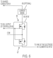
- FIG. 6 is a schematic diagram of a circuit that is suitable for implementing the switches 56, 56' in the designs of FIGS. 3 and 4 and the embodiment of FIG. 5 described above.
- the circuit includes two field effect transistors 66, 67 wired in series, which is a configuration that can pass current in either direction.
- One example of a suitable FET for this circuit is the BSC320N20NSE. (Note that the diodes depicted in FIG. 6 are inherently included within the FETs 66, 67 themselves.)
- the series combination of the two FETs 66, 67 will either conduct or block the flow of electricity, depending on the state of the control input that arrives from one of the digital outputs of the controller 85 described above.
- a current sensing circuit 60 may be positioned in series with the switch 56, 56'.
- the current sensing circuit 60 may be implemented using any of a variety of conventional approaches that will be apparent to persons skilled in the relevant arts.
- the current sensing circuit 60 When the current sensing circuit 60 is included, it generates an output that is representative of the current, and this output is reported back to the controller 85 (shown in FIGS. 3-5 ).
- the controller 85 can then use this information to determine whether the measured current is as expected and take appropriate action if necessary. For example, if an overcurrent condition is detected, the controller 85 can turn off the corresponding switch.
- the current sensing circuit 60 is omitted, it should be replaced with the wire (or other conductor) so that the current can flow between the shared conductor 51 and the top leg of the upper FET 60.
- the current sensing circuit 60 is positioned between the shared conductor 51 and the top leg of the upper FET 60. But in alternative embodiments, the current sensing circuit may be positioned between the bottom leg of the lower FET 67 and the respective electrode element 52, 52'. And in other alternative embodiments (not shown), the current sensing circuit may be integrated within the circuitry of the switch itself.
Landscapes
- Health & Medical Sciences (AREA)
- Life Sciences & Earth Sciences (AREA)
- Engineering & Computer Science (AREA)
- Biomedical Technology (AREA)
- Nuclear Medicine, Radiotherapy & Molecular Imaging (AREA)
- Radiology & Medical Imaging (AREA)
- Animal Behavior & Ethology (AREA)
- General Health & Medical Sciences (AREA)
- Public Health (AREA)
- Veterinary Medicine (AREA)
- Heart & Thoracic Surgery (AREA)
- Neurology (AREA)
- Biophysics (AREA)
- Hospice & Palliative Care (AREA)
- Psychology (AREA)
- Oncology (AREA)
- Neurosurgery (AREA)
- Cardiology (AREA)
- Child & Adolescent Psychology (AREA)
- Developmental Disabilities (AREA)
- Psychiatry (AREA)
- Social Psychology (AREA)
- Electrotherapy Devices (AREA)
- Thermotherapy And Cooling Therapy Devices (AREA)
Claims (8)
- Einrichtung zum Anwenden eines elektrischen Wechselfelds auf einen Körper eines Subjekts, wobei die Einrichtung umfasst:eine Mehrzahl von Sätzen von wenigstens zwei Elektrodenelementen (52, 52');einen Träger (59), der dazu konfiguriert ist, die Sätze von Elektrodenelementen (52, 52') zu halten, sodass die Elektrodenelemente (52, 52') in Kontakt mit dem Körper des Subjekts positioniert werden können;eine Mehrzahl von Temperatursensoren (54), wobei jeder der Sätze von Elektrodenelementen (52, 52') einen einzelnen Temperatursensor (54) aufweist, der positioniert ist, um eine Temperatur an dem jeweiligen der Sätze von Elektrodenelementen (52, 52') zu erfassen und ein jeweiliges Signal zu erzeugen, das die erfasste Temperatur anzeigt;einen elektrischen Leiter;eine Mehrzahl von elektrisch gesteuerten Schaltern (56, 56'), wobei jeder der Schalter (56, 56') in Abhängigkeit von einem Zustand eines jeweiligen Steuereingangs dazu konfiguriert ist, entweder zu ermöglichen, dass ein Strom zwischen dem elektrischen Leiter und den jeweiligen Elektrodenelementen (52, 52') in jedem der Sätze von Elektrodenelementen (52, 52') fließt, oder zu verhindern, dass ein Strom zwischen dem elektrischen Leiter und den jeweiligen Elektrodenelementen (52, 52') in jedem der Sätze von Elektrodenelementen (52, 52') fließt; undeine Steuervorrichtung (85), die dazu konfiguriert ist, den Zustand des Steuereingangs jedes der Schalter (56, 56') in jedem der Sätze von Elektrodenelementen (52, 52') auf Grundlage des Signals zu steuern, das die erfasste Temperatur anzeigt, die von dem jeweiligen Temperatursensor (54) in dem jeweiligen Satz von Elektrodenelementen (52, 52') erzeugt wird;wobei die Elektrodenelemente (52, 52') innerhalb jedes der Sätze von Elektrodenelementen (52, 52') (i) konzentrisch, wobei sich der jeweilige Temperatursensor (54) an dem inneren Elektrodenelement (52) befindet, oder (ii) radial nebeneinander in Form von Tortenstücken angeordnet sind, wobei sich der jeweilige Temperatursensor (54) in der Mitte der Elektrodenelemente (52, 52') befindet.
- Einrichtung nach Anspruch 1, wobei der Träger (59) dazu konfiguriert ist, die Sätze von Elektrodenelementen (52, 52') gegen eine äußere Oberfläche des Körpers des Subjekts zu halten.
- Einrichtung nach Anspruch 1, wobei die Schalter (56, 56') und die Steuervorrichtung (85) auf einem Modul (60) positioniert sind, das über ein Mehrleiterverbindungsstück (42) an dem Träger (59) befestigt ist.
- Einrichtung nach Anspruch 1, wobei die Steuervorrichtung (85) ferner dazu konfiguriert ist, von jedem der Temperatursensoren (54) das jeweilige Signal anzunehmen, das die erfasste Temperatur anzeigt, auf Grundlage der angenommenen Signale ein Tastverhältnis zu bestimmen, mit dem das Elektrodenelement (52, 52') eines gegebenen Satzes von Elektrodenelementen (52, 52') angetrieben werden soll und periodisch den Zustand des Steuereingangs des Schalters (56, 56'), der den Elektrodenelementen (52, 52') des gegebenen Satzes von Elektrodenelementen (52, 52') entspricht, bei dem bestimmten Tastverhältnis umzuschalten, um periodisch zu verhindern, dass Strom zwischen dem elektrischen Leiter und den Elektrodenelementen (52, 52') des gegebenen Satzes von Elektrodenelementen (52, 52') fließt.
- Einrichtung nach Anspruch 1, wobei die Steuervorrichtung (85) ferner dazu konfiguriert ist, von jedem der Temperatursensoren (54) das jeweilige, die erfasste Temperatur anzeigende Signal anzunehmen, auf Grundlage der angenommenen Signale zu bestimmen, ob eine Temperatur an jedem Satz von Elektrodenelementen (52, 52') eine obere Schwelle überschreitet, und, wenn die bestimmte Temperatur an einem gegebenen Satz von Elektrodenelementen (52, 52') die obere Schwelle überschreitet, den Zustand des Steuereingangs wenigstens eines Schalters (56, 56') der Elektrodenelemente (52, 52'), die dem gegebenen Satz von Elektrodenelementen (52, 52') entsprechen, zu steuern, um zu verhindern, dass Strom zwischen dem elektrischen Leiter und dem wenigstens einen der Elektrodenelemente (52, 52') in dem gegebenen Satz von Elektrodenelementen (52, 52') fließt.
- Einrichtung nach Anspruch 1, wobei die Steuervorrichtung (85) ferner dazu konfiguriert ist, das Signal von jedem der Temperatursensoren (54) anzunehmen, Daten, die die Temperatur an jedem der Temperatursensoren (54) beschreiben, an eine zweite Steuervorrichtung (30) zu übertragen, Daten von der zweiten Steuervorrichtung (30) zu empfangen, die angeben, welcher der Schalter (56, 56') ausgeschaltet werden soll, und den Zustand der Steuereingänge der Schalter (56, 56') auf Grundlage der von der zweiten Steuervorrichtung (30) empfangenen Daten zu steuern.
- Einrichtung nach Anspruch 1, wobei die Elektrodenelemente (52, 52') in jedem der Sätze von Elektrodenelementen (52, 52') ein inneres, scheibenförmiges Elektrodenelement (52) und ein äußeres, ringförmiges Elektrodenelement (52') umfassen, das das innere Elektrodenelement (52) umgibt.
- Einrichtung nach Anspruch 1, wobei die Sätze von Elektrodenelementen (52, 52') kapazitiv gekoppelt sind, wobei jedes der Elektrodenelemente (52, 52') eine dielektrische Schicht aufweist.
Applications Claiming Priority (3)
| Application Number | Priority Date | Filing Date | Title |
|---|---|---|---|
| US201862769319P | 2018-11-19 | 2018-11-19 | |
| EP19809920.2A EP3883642B1 (de) | 2018-11-19 | 2019-11-18 | Arrays zur abgabe von tumorbehandlungsfeldern (ttfields) mit selektiv adressierbaren unterelementen |
| PCT/IB2019/059895 WO2020104921A1 (en) | 2018-11-19 | 2019-11-18 | Arrays for delivering tumor treating fields (ttfields) with selectively addressable sub-elements |
Related Parent Applications (2)
| Application Number | Title | Priority Date | Filing Date |
|---|---|---|---|
| EP19809920.2A Division EP3883642B1 (de) | 2018-11-19 | 2019-11-18 | Arrays zur abgabe von tumorbehandlungsfeldern (ttfields) mit selektiv adressierbaren unterelementen |
| EP19809920.2A Division-Into EP3883642B1 (de) | 2018-11-19 | 2019-11-18 | Arrays zur abgabe von tumorbehandlungsfeldern (ttfields) mit selektiv adressierbaren unterelementen |
Publications (3)
| Publication Number | Publication Date |
|---|---|
| EP4019080A1 EP4019080A1 (de) | 2022-06-29 |
| EP4019080B1 true EP4019080B1 (de) | 2025-06-25 |
| EP4019080C0 EP4019080C0 (de) | 2025-06-25 |
Family
ID=68699487
Family Applications (4)
| Application Number | Title | Priority Date | Filing Date |
|---|---|---|---|
| EP22150741.1A Active EP4019080B1 (de) | 2018-11-19 | 2019-11-18 | Arrays zur abgabe von tumorbehandlungsfeldern (ttfields) mit selektiv adressierbaren unterelementen |
| EP21188976.1A Active EP3922300B1 (de) | 2018-11-19 | 2019-11-18 | Arrays zur abgabe von tumorbehandlungsfeldern (ttfields) mit selektiv adressierbaren unterelementen |
| EP21188977.9A Active EP3922301B1 (de) | 2018-11-19 | 2019-11-18 | Arrays zur abgabe von tumorbehandlungsfeldern (ttfields) mit selektiv adressierbaren unterelementen |
| EP19809920.2A Active EP3883642B1 (de) | 2018-11-19 | 2019-11-18 | Arrays zur abgabe von tumorbehandlungsfeldern (ttfields) mit selektiv adressierbaren unterelementen |
Family Applications After (3)
| Application Number | Title | Priority Date | Filing Date |
|---|---|---|---|
| EP21188976.1A Active EP3922300B1 (de) | 2018-11-19 | 2019-11-18 | Arrays zur abgabe von tumorbehandlungsfeldern (ttfields) mit selektiv adressierbaren unterelementen |
| EP21188977.9A Active EP3922301B1 (de) | 2018-11-19 | 2019-11-18 | Arrays zur abgabe von tumorbehandlungsfeldern (ttfields) mit selektiv adressierbaren unterelementen |
| EP19809920.2A Active EP3883642B1 (de) | 2018-11-19 | 2019-11-18 | Arrays zur abgabe von tumorbehandlungsfeldern (ttfields) mit selektiv adressierbaren unterelementen |
Country Status (12)
| Country | Link |
|---|---|
| US (3) | US11395916B2 (de) |
| EP (4) | EP4019080B1 (de) |
| JP (2) | JP7451511B2 (de) |
| KR (1) | KR102747887B1 (de) |
| CN (2) | CN119733171A (de) |
| CA (1) | CA3110448C (de) |
| ES (1) | ES2976808T3 (de) |
| HU (1) | HUE065574T2 (de) |
| IL (1) | IL280843B2 (de) |
| MX (2) | MX2021002624A (de) |
| PL (1) | PL3922301T3 (de) |
| WO (1) | WO2020104921A1 (de) |
Families Citing this family (69)
| Publication number | Priority date | Publication date | Assignee | Title |
|---|---|---|---|---|
| US10779875B2 (en) | 2013-05-06 | 2020-09-22 | Novocure Gmbh | Optimizing treatment using TTfields by changing the frequency during the course of long term tumor treatment |
| US10188851B2 (en) | 2015-10-28 | 2019-01-29 | Novocure Limited | TTField treatment with optimization of electrode positions on the head based on MRI-based conductivity measurements |
| US10821283B2 (en) | 2016-04-04 | 2020-11-03 | Novocure Gmbh | Reducing motility of cancer cells using tumor treating fields (TTFields) |
| AU2017289870B2 (en) | 2016-06-30 | 2021-12-23 | Novocure Gmbh | Arrays for longitudinal delivery of TTFields to a body |
| CN110178029B (zh) | 2017-01-19 | 2021-11-16 | 诺沃库勒有限责任公司 | 用于在施加TTFields的同时在显微镜下观察细胞培养物的系统 |
| US11986647B2 (en) | 2018-09-07 | 2024-05-21 | Novocure Gmbh | Treating autoinflammatory and mitochondrial diseases using an alternating electric field |
| DE112019004248T5 (de) * | 2018-10-12 | 2021-05-12 | Murata Manufacturing Co., Ltd. | Temperatursensorvorrichtung |
| EP3878505B1 (de) | 2018-10-15 | 2023-05-24 | Novocure GmbH | Erzeugung von tumorbehandlungsfeldern (ttfields) mit hoher gleichförmigkeit im ganzen gehirn |
| JP7148722B2 (ja) | 2018-10-25 | 2022-10-05 | ゼーヴ・ボンゾン | 被験者の脊椎構造体に対する交番電界(例えばTTField)の送達 |
| EP4019080B1 (de) | 2018-11-19 | 2025-06-25 | Novocure GmbH | Arrays zur abgabe von tumorbehandlungsfeldern (ttfields) mit selektiv adressierbaren unterelementen |
| CN118079235A (zh) | 2018-11-29 | 2024-05-28 | 诺沃库勒有限责任公司 | 用于递送TTField(肿瘤治疗场)的增强灵活性换能器阵列 |
| EP3974022B1 (de) | 2019-02-26 | 2024-04-17 | Novocure GmbH | Bestimmung einer frequenz für eine ttfields-behandlung basierend auf einem physikalischen parameter von zielkrebszellen |
| PL3917423T3 (pl) | 2019-02-27 | 2025-03-31 | Novocure Gmbh | Dostarczanie pól leczących guzy (pól elektrycznych do leczenia nowotworów ttfields) za pomocą wszczepialnych szyków przetworników |
| US11911610B2 (en) | 2019-03-29 | 2024-02-27 | Novocure Gmbh | Methods for restoring sensitivity to TTFields in TTFields-resistant cancer cells with PTGER3 inhibitors |
| CN113966243A (zh) | 2019-04-17 | 2022-01-21 | 诺沃库勒有限责任公司 | 在不损害隔离的情况下从隔离的系统上传数据 |
| WO2021019403A1 (en) | 2019-07-31 | 2021-02-04 | Yoram Wasserman | Applying tumor treating fields (ttfields) via electrodes embedded into skull implants |
| US12343336B2 (en) | 2019-08-05 | 2025-07-01 | Novocure Gmbh | Increasing cancer cells' sensitivity to tumor treating fields (TTFields) by inhibiting IL11 activity |
| US11890467B2 (en) | 2019-08-30 | 2024-02-06 | Novocure Gmbh | Delivering tumor treating fields (TTFields) to the neck |
| JP7652780B2 (ja) | 2019-12-20 | 2025-03-27 | ノボキュア ゲーエムベーハー | 腫瘍治療電場を動物試験被験体に提供するための治療組立体 |
| MX2022006135A (es) | 2019-12-31 | 2022-06-17 | Novocure Gmbh | Generador de ondas sinusoidales de alta eficiencia, alto voltaje, que evita los picos durante los ajustes de amplitud y la conmutacion de canales. |
| US12121739B2 (en) | 2019-12-31 | 2024-10-22 | Novocure Gmbh | Methods, systems, and apparatuses for managing temperatures induced by alternating fields |
| PL4074367T3 (pl) | 2019-12-31 | 2023-07-31 | Novocure Gmbh | Szyki do dostarczania zmiennych pól elektrycznych do leczenia nowotworów (ttfields) z indywidualnie dostępnymi elementami elektrody i czujnikami temperatury |
| US20210299440A1 (en) | 2020-03-30 | 2021-09-30 | Novocure Gmbh | Intravenous / Intra-Spinal / Intra-Cavity / Intraventricular Delivery of TTFields (Tumor Treating Fields) for Treating Cancer and Metastases |
| IL295251A (en) | 2020-04-24 | 2022-10-01 | Novocure Gmbh | Using alternating electric fields to increase permeability of the blood brain barrier |
| US11818943B2 (en) | 2020-06-25 | 2023-11-14 | Novocure Gmbh | Fabricating organic light emitting diodes (OLEDs) using tubulin |
| WO2022064339A1 (en) * | 2020-09-25 | 2022-03-31 | Novocure Gmbh | Varying the metallization area on individual electrode elements in a tumor treating fields (ttfields) system to maximize current without overheating |
| WO2022069939A1 (en) * | 2020-09-30 | 2022-04-07 | Novocure Gmbh | Connector for detachable array |
| US12194295B2 (en) | 2020-09-30 | 2025-01-14 | Novocure Gmbh | Method and apparatus for delivering tumor treating fields to a torso, and method for determining locations for transducers to deliver tumor treating fields |
| KR20230074815A (ko) * | 2020-09-30 | 2023-05-31 | 노보큐어 게엠베하 | 탈거 가능한 어레이를 위한 커넥터 |
| WO2022130183A2 (en) * | 2020-12-17 | 2022-06-23 | Novocure Gmbh | Pyroelectric-based temperature sensing of transducer arrays for applying tumor treating fields (ttfields) |
| EP4570303A3 (de) * | 2020-12-21 | 2025-07-30 | Novocure GmbH | Optimierung einer verbundelektrode |
| US20220241603A1 (en) * | 2021-02-03 | 2022-08-04 | Novocure Gmbh | Varying Parameters of Tumor Treating Fields (TTFields) Treatment to Overcome Treatment Resistance |
| CN117083103A (zh) | 2021-02-17 | 2023-11-17 | 诺沃库勒有限责任公司 | 具有具备单独可调整的有源面积的电极元件集合的用于输送肿瘤治疗场(TTFields)的阵列 |
| EP4304704A1 (de) | 2021-03-12 | 2024-01-17 | Novocure GmbH | Verfahren zur behandlung von krankheiten durch verschieben des makrophagenphänotyps mit alternierenden elektrischen feldern |
| US20220305277A1 (en) * | 2021-03-23 | 2022-09-29 | Novocure Gmbh | Methods and apparatuses for detecting and responding to changes in a subject |
| WO2022201060A1 (en) | 2021-03-23 | 2022-09-29 | Novocure Gmbh | Method and apparatus for detecting and responding to changes in subjects |
| EP4284489B1 (de) | 2021-03-31 | 2025-07-16 | Novocure Gmbh | Impedanztomografie mit elektroden eines tumorbehandlungsfeldsystems |
| CR20240027A (es) * | 2021-06-22 | 2024-05-28 | Lifebridge Innovations Pbc | Aparato y método para mejorar la terapia de campo eléctrico para reducir tumores sólidos |
| MX2023014225A (es) * | 2021-06-30 | 2024-01-24 | Novocure Gmbh | Uso de condensadores para regular la corriente en matrices de transductores para aplicar campos de tratamiento de tumores (ttfields). |
| JP2024524338A (ja) * | 2021-06-30 | 2024-07-05 | ノボキュア ゲーエムベーハー | 腫瘍治療場(ttfield)を送達し、インピーダンスを測定するためのシステムおよび方法 |
| WO2023002250A1 (en) * | 2021-07-21 | 2023-01-26 | Novocure Gmbh | Conductive pad generating tumor treating field and methods of production and use thereof |
| CN113856052B (zh) * | 2021-09-28 | 2022-10-14 | 江苏海莱新创医疗科技有限公司 | 主动吸热型电极、肿瘤电场治疗系统及温度控制方法 |
| CN114099944A (zh) * | 2021-11-22 | 2022-03-01 | 杭州佑生医疗科技有限公司 | 外敷电极贴片和细胞分裂抑制装置 |
| US20250177764A1 (en) * | 2021-12-22 | 2025-06-05 | Jiangsu Healthy Life Innovation Medical Technology Co., Ltd | Tumor treating field system and method for applying alternating current signals thereof |
| CN114177527A (zh) * | 2021-12-24 | 2022-03-15 | 江苏海莱新创医疗科技有限公司 | 用于向受检者的身体施加电场的装置和系统 |
| US20250177765A1 (en) * | 2021-12-22 | 2025-06-05 | Jiangsu Healthy Life Innovation Medical Technology Co., Ltd | Tumor treating fields system and insulated electrode thereof |
| CN114288550A (zh) * | 2021-12-24 | 2022-04-08 | 江苏海莱新创医疗科技有限公司 | 用于向受检者的身体施加电场的装置、系统及其温度控制方法 |
| US20250177743A1 (en) * | 2021-12-22 | 2025-06-05 | Jiangsu Healthy Life Innovation Medical Technology Co., Ltd | Tumor treating fields system and alternating current signal application method thereof |
| US12377280B2 (en) | 2021-12-30 | 2025-08-05 | Novocure Gmbh | Selecting values of parameters for treatment using tumor treating fields (TTFields) |
| CN114534091B (zh) * | 2022-02-17 | 2022-09-09 | 湖南安泰康成生物科技有限公司 | 利用电场抑制肿瘤增殖的设备及其控制装置 |
| JP2025511071A (ja) * | 2022-03-30 | 2025-04-15 | ノボキュア ゲーエムベーハー | インターリーブ冷却期間による腫瘍治療場のピーク強度強化 |
| IL314392A (en) | 2022-03-30 | 2024-09-01 | Novocure Gmbh | Reducing electrosensation whilst treating a subject using alternating electric fields by pairing transducer arrays together |
| US20240108887A1 (en) * | 2022-09-30 | 2024-04-04 | Novocure Gmbh | Reducing Electrosensation While Treating a Subject Using Alternating Electric Fields by Deactivating Selected Electrode Elements |
| WO2024076029A1 (ko) * | 2022-10-07 | 2024-04-11 | 주식회사 필드큐어 | 전극 어레이에서의 온도 측정 장치 |
| KR102853607B1 (ko) | 2022-10-25 | 2025-09-03 | 주식회사 필드큐어 | 전기장 전달 시스템 및 방법 |
| CN115671556A (zh) * | 2022-10-27 | 2023-02-03 | 江苏海莱新创医疗科技有限公司 | 肿瘤电场治疗系统及其电极片、肿瘤治疗设备 |
| CN115980490B (zh) * | 2022-12-30 | 2024-04-19 | 江苏海莱新创医疗科技有限公司 | 电极片的质量检测系统及方法、转接器、电场发生器 |
| CN115920230A (zh) * | 2022-12-30 | 2023-04-07 | 江苏海莱新创医疗科技有限公司 | 电极片、电场治疗系统及控制方法 |
| CN115845260B (zh) * | 2022-12-30 | 2024-07-05 | 江苏海莱新创医疗科技有限公司 | 肿瘤电场治疗系统及其电极片、温度检测方法 |
| CN116271523B (zh) * | 2022-12-30 | 2024-03-29 | 江苏海莱新创医疗科技有限公司 | 电极片、电极片识别方法、肿瘤电场治疗系统及治疗设备 |
| KR20240072925A (ko) | 2022-11-17 | 2024-05-24 | 주식회사 필드큐어 | 임피던스 보상을 위한 전극 어레이 |
| IL320472A (en) * | 2022-11-30 | 2025-06-01 | Novocure Gmbh | Transducer arrays with alternative array materials |
| CN117839070B (zh) * | 2022-12-30 | 2025-08-19 | 江苏海莱新创医疗科技有限公司 | 肿瘤电场治疗系统、肿瘤治疗设备及电极片温度检测方法 |
| US12268863B2 (en) | 2023-02-06 | 2025-04-08 | Novocure Gmbh | Shiftable transducer array with anisotropic material layer |
| KR20250143309A (ko) * | 2023-02-06 | 2025-10-01 | 노보큐어 게엠베하 | 이방성 재료 층을 갖는 이동 가능한 트랜스듀서 어레이 |
| SE2350150A1 (en) * | 2023-02-15 | 2024-08-16 | Force Oncology Ab | Tumor treating fields (ttfields) equipment configurations for improved ease-of-use |
| KR20240129583A (ko) | 2023-02-20 | 2024-08-27 | 주식회사 필드큐어 | 대상체에 전기장을 전달하는 임베디드 전극 |
| CN116808435B (zh) * | 2023-04-21 | 2024-11-22 | 上海微场医疗科技有限公司 | 电场治疗设备、电子设备和可读存储介质 |
| CN120114753A (zh) * | 2023-12-26 | 2025-06-10 | 杭州海莱新创医疗科技有限公司 | 一种电极片温度检测方法 |
Family Cites Families (64)
| Publication number | Priority date | Publication date | Assignee | Title |
|---|---|---|---|---|
| DE3419439C1 (de) * | 1984-05-24 | 1985-11-21 | Eckhard Dr. 8000 München Alt | Belastungsabhaengig frequenzvariabler Herzschrittmacher |
| US5938597A (en) | 1995-05-04 | 1999-08-17 | Stratbucker; Robert A. | Electrocardiograph bioelectric interface system and method of use |
| US5974344A (en) | 1998-03-02 | 1999-10-26 | Shoemaker, Ii; Charles | Wound care electrode |
| US6558378B2 (en) | 1998-05-05 | 2003-05-06 | Cardiac Pacemakers, Inc. | RF ablation system and method having automatic temperature control |
| US8447395B2 (en) | 2000-02-17 | 2013-05-21 | Novocure Ltd | Treating bacteria with electric fields |
| US8175698B2 (en) | 2000-02-17 | 2012-05-08 | Novocure Ltd. | Treating bacteria with electric fields |
| US7146210B2 (en) | 2000-02-17 | 2006-12-05 | Standen Ltd. | Apparatus and method for optimizing tumor treatment efficiency by electric fields |
| CN1416466A (zh) | 2000-02-17 | 2003-05-07 | 约朗姆·帕尔蒂 | 破坏正在分裂的细胞的方法和装置 |
| US6868289B2 (en) | 2002-10-02 | 2005-03-15 | Standen Ltd. | Apparatus for treating a tumor or the like and articles incorporating the apparatus for treatment of the tumor |
| US7016725B2 (en) | 2001-11-06 | 2006-03-21 | Standen Ltd. | Method and apparatus for destroying dividing cells |
| US7089054B2 (en) | 2002-10-02 | 2006-08-08 | Standen Ltd. | Apparatus and method for treating a tumor or the like |
| US7599746B2 (en) | 2000-02-17 | 2009-10-06 | Standen Ltd | Apparatus and method for preventing the spread of cancerous metastases and for elimination of metastases |
| US7136699B2 (en) | 2002-10-02 | 2006-11-14 | Standen, Ltd. | Apparatus for destroying dividing cells |
| US7565206B2 (en) | 2000-02-17 | 2009-07-21 | Standen Ltd. | Treating a tumor or the like with electric fields at different orientations |
| US7171276B2 (en) | 2001-06-29 | 2007-01-30 | Abbott Laboratories | Hydrogel and scrim assembly for use with electro-acupuncture device with stimulation electrodes |
| US20040122500A1 (en) | 2002-12-19 | 2004-06-24 | Kimberly-Clark Worldwide, Inc. | Electrode for utilizing edge effect to create uniform current density |
| US20050222646A1 (en) | 2004-04-06 | 2005-10-06 | Kai Kroll | Method and device for treating cancer with modified output electrical therapy |
| CN1976738B (zh) | 2004-04-23 | 2010-09-01 | 诺沃库勒有限公司 | 使用不同频率的电场治疗肿瘤等 |
| DK1833552T3 (da) | 2004-12-07 | 2010-08-02 | Standen Ltd | Elektroder til anbringelse af et elektrisk felt in-vivo i en længere tidsperiode |
| US20070093788A1 (en) | 2005-09-30 | 2007-04-26 | Darrick Carter | Iontophoresis method and apparatus for systemic delivery of active agents |
| PT1933937E (pt) | 2005-10-03 | 2015-04-23 | Novocure Ltd | Optimização de características de um campo eléctrico para aumentar o efeito do campo em células proliferantes |
| US8019414B2 (en) | 2006-04-05 | 2011-09-13 | Novocure Ltd. | Treating cancer using electromagnetic fields in combination with other treatment regimens |
| US8465533B2 (en) | 2007-03-06 | 2013-06-18 | Novocure Limited | Treating cancer using electromagnetic fields in combination with photodynamic therapy |
| US8388612B2 (en) * | 2007-05-11 | 2013-03-05 | Covidien Lp | Temperature monitoring return electrode |
| PT2183024T (pt) | 2007-08-14 | 2019-08-01 | Novocure Ltd | Tratando parasitas com campos elétricos |
| US8715203B2 (en) * | 2007-09-17 | 2014-05-06 | Novocure Limited | Composite electrode |
| US8295902B2 (en) | 2008-11-11 | 2012-10-23 | Shifamed Holdings, Llc | Low profile electrode assembly |
| US9655669B2 (en) | 2013-05-06 | 2017-05-23 | Novocure Limited | Optimizing treatment using TTFields by changing the frequency during the course of long term tumor treatment |
| US10779875B2 (en) | 2013-05-06 | 2020-09-22 | Novocure Gmbh | Optimizing treatment using TTfields by changing the frequency during the course of long term tumor treatment |
| CN203588093U (zh) * | 2013-12-05 | 2014-05-07 | 四川恒明科技开发有限公司 | 一种用于电极片上的双重温度控制装置 |
| US20190117963A1 (en) | 2014-07-25 | 2019-04-25 | Loyalty Based Innovations, LLC | Apparatus and method for treating multiple tumors in patients with metastatic disease by electric fields |
| US9833617B2 (en) | 2014-07-25 | 2017-12-05 | Loyalty Based Innovations, LLC | Apparatus and method for treating multiple tumors in patients with metastatic disease by electric fields |
| EP3302682A1 (de) | 2015-05-29 | 2018-04-11 | Cerevast Medical Inc. | Verfahren und vorrichtung zur transdermalen elektrischen stimulation |
| US9910453B2 (en) | 2015-09-25 | 2018-03-06 | Novocure Limited | High voltage, high efficiency sine wave generator with pre-set frequency and adjustable amplitude |
| US10188851B2 (en) | 2015-10-28 | 2019-01-29 | Novocure Limited | TTField treatment with optimization of electrode positions on the head based on MRI-based conductivity measurements |
| IL296167A (en) * | 2016-02-21 | 2022-11-01 | Tech Innosphere Eng Ltd | Noninvasive electric brain stimulation system |
| US10821283B2 (en) | 2016-04-04 | 2020-11-03 | Novocure Gmbh | Reducing motility of cancer cells using tumor treating fields (TTFields) |
| AU2017289870B2 (en) | 2016-06-30 | 2021-12-23 | Novocure Gmbh | Arrays for longitudinal delivery of TTFields to a body |
| CA2972699A1 (en) | 2016-07-10 | 2018-01-10 | Novocure Limited | Synchronizing tumor cells to the g2/m phase using ttfields combined with taxane or other anti-microtubule agents |
| US11097101B2 (en) | 2016-08-18 | 2021-08-24 | Novocure Gmbh | Temperature measurement in arrays for delivering TTFields |
| PL3554631T3 (pl) | 2016-12-13 | 2022-09-12 | Novocure Gmbh | Leczenie pacjentów polami ttfields ze zoptymalizowanymi pozycjami elektrod z wykorzystaniem odkształcalnych matryc |
| CN110178029B (zh) | 2017-01-19 | 2021-11-16 | 诺沃库勒有限责任公司 | 用于在施加TTFields的同时在显微镜下观察细胞培养物的系统 |
| CN107281635B (zh) * | 2017-07-26 | 2024-01-16 | 江苏海莱新创医疗科技有限公司 | 电极理疗装置和电极定位方法 |
| EP3773726B1 (de) | 2018-04-09 | 2024-06-05 | Novocure GmbH | Behandlung von tumoren mit ttfields und einem aurora-kinase-inhibitor |
| KR102687814B1 (ko) | 2018-04-10 | 2024-07-24 | 지브 봄존 | 서로 다른 반복 시간을 가지는 두 개의 MRI 이미지들로부터 얻어진 1MHz 미만 저주파 교류 전도도 추산치 |
| DK3838333T3 (da) | 2018-07-03 | 2023-03-27 | Univ Leland Stanford Junior | Anvendelse af elektriske vekselfelter til forøgelse af cellmembranpermeabilitet |
| EP3820562A1 (de) | 2018-07-10 | 2021-05-19 | Novocure GmbH | Hemmung der viralen infektion mit alternierenden elektrischen feldern |
| US11179322B2 (en) | 2018-07-10 | 2021-11-23 | Novocure Gmbh | Methods and compositions for treating tumors with TTFields and sorafenib |
| MX2020013431A (es) | 2018-07-18 | 2021-05-27 | Novocure Gmbh | Uso de densidad de perdida de potencia y mediciones relacionadas para cuantificar la dosis de campos de tratamiento de tumores (ttfield). |
| CN112618956B (zh) | 2018-08-23 | 2025-06-27 | 诺沃库勒有限责任公司 | 使用交变电场来提高血脑屏障的通透性 |
| US11160977B2 (en) | 2018-09-04 | 2021-11-02 | Novocure Gmbh | Delivering tumor treating fields (TTFields) to the infratentorial brain |
| CN112770806B (zh) | 2018-09-07 | 2025-12-05 | 诺沃库勒有限责任公司 | 使用交变电场治疗自身免疫性疾病以减少t细胞的增殖 |
| US20200108031A1 (en) | 2018-10-05 | 2020-04-09 | Novocure Gmbh | Treating Tumors Using TTFields Combined with ABT-751 |
| JP7282411B2 (ja) | 2018-10-23 | 2023-05-29 | ザ ボード オブ トラスティーズ オブ ザ レランド スタンフォード ジュニア ユニバーシティー | 交流電場を使用する、幹細胞に基づく療法におけるテラトーマ形成の予防及び処置 |
| JP7148722B2 (ja) | 2018-10-25 | 2022-10-05 | ゼーヴ・ボンゾン | 被験者の脊椎構造体に対する交番電界(例えばTTField)の送達 |
| US20200146586A1 (en) | 2018-11-14 | 2020-05-14 | Novocure Gmbh | Creating Accurate Computational Head Models of Patients Using Datasets Combining MRI and CT Images |
| EP4019080B1 (de) | 2018-11-19 | 2025-06-25 | Novocure GmbH | Arrays zur abgabe von tumorbehandlungsfeldern (ttfields) mit selektiv adressierbaren unterelementen |
| CN118079235A (zh) | 2018-11-29 | 2024-05-28 | 诺沃库勒有限责任公司 | 用于递送TTField(肿瘤治疗场)的增强灵活性换能器阵列 |
| US11276171B2 (en) | 2019-01-08 | 2022-03-15 | Novocure Gmbh | Evaluating quality of segmentation of an image into different types of tissue for planning treatment using tumor treating fields (TTFields) |
| EP3911299A1 (de) | 2019-02-22 | 2021-11-24 | Novocure GmbH | Behandlung von magenkrebs mittels ttfields kombiniert mit xelox oder folfox |
| EP3974022B1 (de) | 2019-02-26 | 2024-04-17 | Novocure GmbH | Bestimmung einer frequenz für eine ttfields-behandlung basierend auf einem physikalischen parameter von zielkrebszellen |
| PL3917423T3 (pl) | 2019-02-27 | 2025-03-31 | Novocure Gmbh | Dostarczanie pól leczących guzy (pól elektrycznych do leczenia nowotworów ttfields) za pomocą wszczepialnych szyków przetworników |
| US11911610B2 (en) | 2019-03-29 | 2024-02-27 | Novocure Gmbh | Methods for restoring sensitivity to TTFields in TTFields-resistant cancer cells with PTGER3 inhibitors |
| US12369967B2 (en) | 2019-12-16 | 2025-07-29 | Lifebridge Innovations, Pbc | Apparatus and method for optimizing and adapting treatment of multiple tumors in patients with metastatic disease by electric field |
-
2019
- 2019-11-18 EP EP22150741.1A patent/EP4019080B1/de active Active
- 2019-11-18 CN CN202411889059.0A patent/CN119733171A/zh active Pending
- 2019-11-18 KR KR1020217018534A patent/KR102747887B1/ko active Active
- 2019-11-18 HU HUE21188977A patent/HUE065574T2/hu unknown
- 2019-11-18 EP EP21188976.1A patent/EP3922300B1/de active Active
- 2019-11-18 EP EP21188977.9A patent/EP3922301B1/de active Active
- 2019-11-18 JP JP2021520100A patent/JP7451511B2/ja active Active
- 2019-11-18 WO PCT/IB2019/059895 patent/WO2020104921A1/en not_active Ceased
- 2019-11-18 EP EP19809920.2A patent/EP3883642B1/de active Active
- 2019-11-18 PL PL21188977.9T patent/PL3922301T3/pl unknown
- 2019-11-18 CA CA3110448A patent/CA3110448C/en active Active
- 2019-11-18 IL IL280843A patent/IL280843B2/en unknown
- 2019-11-18 ES ES21188977T patent/ES2976808T3/es active Active
- 2019-11-18 US US16/686,918 patent/US11395916B2/en active Active
- 2019-11-18 CN CN201980076291.3A patent/CN113015553B/zh active Active
- 2019-11-18 MX MX2021002624A patent/MX2021002624A/es unknown
-
2021
- 2021-03-05 MX MX2024009505A patent/MX2024009505A/es unknown
-
2022
- 2022-06-09 US US17/836,221 patent/US12029898B2/en active Active
-
2024
- 2024-03-05 JP JP2024032958A patent/JP2024055977A/ja active Pending
- 2024-06-10 US US18/738,457 patent/US20240325739A1/en active Pending
Also Published As
Similar Documents
| Publication | Publication Date | Title |
|---|---|---|
| EP4019080B1 (de) | Arrays zur abgabe von tumorbehandlungsfeldern (ttfields) mit selektiv adressierbaren unterelementen | |
| US12434053B2 (en) | Arrays for delivering tumor treating fields (TTFields) with individually accessible electrode elements and temperature sensors | |
| US11607543B2 (en) | Delivering tumor treating fields (TTFields) using implantable transducer arrays | |
| HK40067065A (en) | Arrays for delivering tumor treating fields (ttfields) with selectively addressable sub-elements | |
| HK40067065B (en) | Arrays for delivering tumor treating fields (ttfields) with selectively addressable sub-elements | |
| HK40057424B (en) | Arrays for delivering tumor treating fields (ttfields) with selectively addressable sub-elements | |
| HK40057419B (en) | Arrays for delivering tumor treating fields (ttfields) with selectively addressable sub-elements | |
| HK40057419A (en) | Arrays for delivering tumor treating fields (ttfields) with selectively addressable sub-elements | |
| HK40057424A (en) | Arrays for delivering tumor treating fields (ttfields) with selectively addressable sub-elements | |
| HK40050991B (en) | Arrays for delivering tumor treating fields (ttfields) with selectively addressable sub-elements | |
| HK40050991A (en) | Arrays for delivering tumor treating fields (ttfields) with selectively addressable sub-elements | |
| HK40074421B (en) | Arrays for delivering tumor treating fields (ttfields) with individually accessible electrode elements and temperature sensors | |
| HK40074421A (en) | Arrays for delivering tumor treating fields (ttfields) with individually accessible electrode elements and temperature sensors |
Legal Events
| Date | Code | Title | Description |
|---|---|---|---|
| PUAI | Public reference made under article 153(3) epc to a published international application that has entered the european phase |
Free format text: ORIGINAL CODE: 0009012 |
|
| STAA | Information on the status of an ep patent application or granted ep patent |
Free format text: STATUS: THE APPLICATION HAS BEEN PUBLISHED |
|
| STAA | Information on the status of an ep patent application or granted ep patent |
Free format text: STATUS: REQUEST FOR EXAMINATION WAS MADE |
|
| AC | Divisional application: reference to earlier application |
Ref document number: 3883642 Country of ref document: EP Kind code of ref document: P |
|
| AK | Designated contracting states |
Kind code of ref document: A1 Designated state(s): AL AT BE BG CH CY CZ DE DK EE ES FI FR GB GR HR HU IE IS IT LI LT LU LV MC MK MT NL NO PL PT RO RS SE SI SK SM TR |
|
| 17P | Request for examination filed |
Effective date: 20220531 |
|
| RBV | Designated contracting states (corrected) |
Designated state(s): AL AT BE BG CH CY CZ DE DK EE ES FI FR GB GR HR HU IE IS IT LI LT LU LV MC MK MT NL NO PL PT RO RS SE SI SK SM TR |
|
| REG | Reference to a national code |
Ref country code: HK Ref legal event code: DE Ref document number: 40067065 Country of ref document: HK |
|
| STAA | Information on the status of an ep patent application or granted ep patent |
Free format text: STATUS: EXAMINATION IS IN PROGRESS |
|
| 17Q | First examination report despatched |
Effective date: 20240705 |
|
| GRAP | Despatch of communication of intention to grant a patent |
Free format text: ORIGINAL CODE: EPIDOSNIGR1 |
|
| STAA | Information on the status of an ep patent application or granted ep patent |
Free format text: STATUS: GRANT OF PATENT IS INTENDED |
|
| RIC1 | Information provided on ipc code assigned before grant |
Ipc: A61N 1/05 20060101ALN20250203BHEP Ipc: A61N 1/04 20060101ALN20250203BHEP Ipc: A61N 1/40 20060101ALI20250203BHEP Ipc: A61N 1/36 20060101AFI20250203BHEP |
|
| INTG | Intention to grant announced |
Effective date: 20250214 |
|
| GRAJ | Information related to disapproval of communication of intention to grant by the applicant or resumption of examination proceedings by the epo deleted |
Free format text: ORIGINAL CODE: EPIDOSDIGR1 |
|
| STAA | Information on the status of an ep patent application or granted ep patent |
Free format text: STATUS: EXAMINATION IS IN PROGRESS |
|
| GRAS | Grant fee paid |
Free format text: ORIGINAL CODE: EPIDOSNIGR3 |
|
| STAA | Information on the status of an ep patent application or granted ep patent |
Free format text: STATUS: GRANT OF PATENT IS INTENDED |
|
| GRAP | Despatch of communication of intention to grant a patent |
Free format text: ORIGINAL CODE: EPIDOSNIGR1 |
|
| RAP3 | Party data changed (applicant data changed or rights of an application transferred) |
Owner name: NOVOCURE GMBH |
|
| GRAA | (expected) grant |
Free format text: ORIGINAL CODE: 0009210 |
|
| STAA | Information on the status of an ep patent application or granted ep patent |
Free format text: STATUS: THE PATENT HAS BEEN GRANTED |
|
| INTC | Intention to grant announced (deleted) | ||
| RIC1 | Information provided on ipc code assigned before grant |
Ipc: A61N 1/05 20060101ALN20250508BHEP Ipc: A61N 1/04 20060101ALN20250508BHEP Ipc: A61N 1/40 20060101ALI20250508BHEP Ipc: A61N 1/36 20060101AFI20250508BHEP |
|
| INTG | Intention to grant announced |
Effective date: 20250514 |
|
| AC | Divisional application: reference to earlier application |
Ref document number: 3883642 Country of ref document: EP Kind code of ref document: P |
|
| AK | Designated contracting states |
Kind code of ref document: B1 Designated state(s): AL AT BE BG CH CY CZ DE DK EE ES FI FR GB GR HR HU IE IS IT LI LT LU LV MC MK MT NL NO PL PT RO RS SE SI SK SM TR |
|
| REG | Reference to a national code |
Ref country code: GB Ref legal event code: FG4D |
|
| REG | Reference to a national code |
Ref country code: CH Ref legal event code: EP |
|
| REG | Reference to a national code |
Ref country code: CH Ref legal event code: EP |
|
| REG | Reference to a national code |
Ref country code: IE Ref legal event code: FG4D |
|
| REG | Reference to a national code |
Ref country code: DE Ref legal event code: R096 Ref document number: 602019071814 Country of ref document: DE |
|
| U01 | Request for unitary effect filed |
Effective date: 20250721 |
|
| U07 | Unitary effect registered |
Designated state(s): AT BE BG DE DK EE FI FR IT LT LU LV MT NL PT RO SE SI Effective date: 20250728 |
|
| PG25 | Lapsed in a contracting state [announced via postgrant information from national office to epo] |
Ref country code: GR Free format text: LAPSE BECAUSE OF FAILURE TO SUBMIT A TRANSLATION OF THE DESCRIPTION OR TO PAY THE FEE WITHIN THE PRESCRIBED TIME-LIMIT Effective date: 20250926 Ref country code: NO Free format text: LAPSE BECAUSE OF FAILURE TO SUBMIT A TRANSLATION OF THE DESCRIPTION OR TO PAY THE FEE WITHIN THE PRESCRIBED TIME-LIMIT Effective date: 20250925 |
|
| PG25 | Lapsed in a contracting state [announced via postgrant information from national office to epo] |
Ref country code: HR Free format text: LAPSE BECAUSE OF FAILURE TO SUBMIT A TRANSLATION OF THE DESCRIPTION OR TO PAY THE FEE WITHIN THE PRESCRIBED TIME-LIMIT Effective date: 20250625 |
|
| PG25 | Lapsed in a contracting state [announced via postgrant information from national office to epo] |
Ref country code: RS Free format text: LAPSE BECAUSE OF FAILURE TO SUBMIT A TRANSLATION OF THE DESCRIPTION OR TO PAY THE FEE WITHIN THE PRESCRIBED TIME-LIMIT Effective date: 20250925 |