EP4017789B1 - Verstärkung für einen hohlkörper - Google Patents
Verstärkung für einen hohlkörper Download PDFInfo
- Publication number
- EP4017789B1 EP4017789B1 EP20758278.4A EP20758278A EP4017789B1 EP 4017789 B1 EP4017789 B1 EP 4017789B1 EP 20758278 A EP20758278 A EP 20758278A EP 4017789 B1 EP4017789 B1 EP 4017789B1
- Authority
- EP
- European Patent Office
- Prior art keywords
- bottom wall
- profile
- reinforcement
- shaped section
- main direction
- Prior art date
- Legal status (The legal status is an assumption and is not a legal conclusion. Google has not performed a legal analysis and makes no representation as to the accuracy of the status listed.)
- Active
Links
Images
Classifications
-
- B—PERFORMING OPERATIONS; TRANSPORTING
- B62—LAND VEHICLES FOR TRAVELLING OTHERWISE THAN ON RAILS
- B62D—MOTOR VEHICLES; TRAILERS
- B62D25/00—Superstructure or monocoque structure sub-units; Parts or details thereof not otherwise provided for
- B62D25/20—Floors or bottom sub-units
- B62D25/2009—Floors or bottom sub-units in connection with other superstructure subunits
- B62D25/2018—Floors or bottom sub-units in connection with other superstructure subunits the subunits being front structures
-
- B—PERFORMING OPERATIONS; TRANSPORTING
- B62—LAND VEHICLES FOR TRAVELLING OTHERWISE THAN ON RAILS
- B62D—MOTOR VEHICLES; TRAILERS
- B62D27/00—Connections between superstructure or understructure sub-units
- B62D27/02—Connections between superstructure or understructure sub-units rigid
- B62D27/026—Connections by glue bonding
-
- B—PERFORMING OPERATIONS; TRANSPORTING
- B62—LAND VEHICLES FOR TRAVELLING OTHERWISE THAN ON RAILS
- B62D—MOTOR VEHICLES; TRAILERS
- B62D29/00—Superstructures, understructures, or sub-units thereof, characterised by the material thereof
- B62D29/001—Superstructures, understructures, or sub-units thereof, characterised by the material thereof characterised by combining metal and synthetic material
- B62D29/002—Superstructures, understructures, or sub-units thereof, characterised by the material thereof characterised by combining metal and synthetic material a foamable synthetic material or metal being added in situ
-
- B—PERFORMING OPERATIONS; TRANSPORTING
- B62—LAND VEHICLES FOR TRAVELLING OTHERWISE THAN ON RAILS
- B62D—MOTOR VEHICLES; TRAILERS
- B62D29/00—Superstructures, understructures, or sub-units thereof, characterised by the material thereof
- B62D29/001—Superstructures, understructures, or sub-units thereof, characterised by the material thereof characterised by combining metal and synthetic material
- B62D29/005—Superstructures, understructures, or sub-units thereof, characterised by the material thereof characterised by combining metal and synthetic material preformed metal and synthetic material elements being joined together, e.g. by adhesives
Definitions
- the invention relates to the reinforcement of U-section profiles, in particular of the body structure of motor vehicles, and more particularly of the front stretchers of motor vehicles.
- Some body parts that ensure the rigidity of the vehicles on which they are installed have a structure forming one or more hollow bodies.
- the (complete) blocking of the hollow body(ies) of the front side rails by these profiles has the disadvantage of creating a blockage at the inlets of water and salts coming from wheel projections or water flows from the upper parts of motor vehicles, but also of creating a blockage for cataphoretic coating fluids. This has the major consequence of reducing the anti-corrosion guarantee of the vehicles, and therefore of weakening the structure of the front side rails.
- the published patent document EP1 387 789 B1 describes a reinforcing element for motor vehicle parts having hollow bodies.
- This reinforcing element which may be made of metal or plastic, has a U-shaped or M-shaped cross-section which is substantially conformed to the cross-section of the hollow body into which it is adapted to be inserted.
- Ribs are also present on the external face of the lower wall of this reinforcing element. These ribs or extensions have the function of delimiting one or more areas to which an expanding adhesive material can be applied. The function of this expanding material is to connect the reinforcing element to the inner face of the hollow body of the body part and thus contribute to its consolidation.
- this reinforcing element may also have orifices or channels to drain water that may accumulate in the hollow body(ies) of the body part, it does not guarantee effective and complete drainage over time, and thus limit or prevent corrosion of the hollow bodies and therefore the embrittlement over time of the body parts concerned.
- the invention aims to overcome at least one of the drawbacks of the aforementioned state of the art. More particularly, the invention aims to effectively prevent corrosion of hollow profiles, in a manner that is simple to implement.
- the invention relates to a beam comprising a U-shaped section profile with two side walls and a bottom wall; a reinforcement housed in the U-shaped section of the profile and fixed to said profile by an expanding adhesive between the side walls of the U-shaped section and said reinforcement.
- the reinforcement forms a partitioned structure extending in a main direction and comprising two opposite side faces facing the side walls of the profile and a bottom face facing the bottom wall of said profile.
- the partitioned structure comprises on the bottom face two ribs extending in the main direction so as to delimit with the bottom wall of the profile a ventilation channel.
- a plate fixed to the profile closes the U-shaped section.
- the expanding adhesive extends from the side walls towards the bottom wall of the U-shaped section and stops at the ribs of the reinforcement so as to form the ventilation channel.
- the partitioned structure comprises, on the bottom face, between the two ribs and on at least one section of said structure, a bottom wall provided with ventilation orifices.
- the ventilation orifices have an average diameter less than 10 mm and greater than 5 mm.
- the partitions form chambers, the bottom wall of the partitioned structure extending in the main direction along several chambers.
- the bottom wall of the partitioned structure extends transversely to the main direction beyond the two ribs to the lateral faces of said structure.
- the main direction forms an elbow, the bottom wall of the partitioned structure extending continuously along said elbow.
- an expandable adhesive material is applied to the side faces of the reinforcement.
- the bottom wall of the U-shaped section of the profile comprises openings along the main direction, in direct contact with the ventilation channel.
- the beam forms an elbow and is a longitudinal structural beam of a motor vehicle, called a stretcher.
- the invention also relates to a motor vehicle comprising a floor; a front lower apron fixed to a front edge of the floor; and two longitudinal structural beams extending under a front part of the floor towards an engine compartment of the motor vehicle; remarkable in that each of the two longitudinal structural beams is in accordance with the invention.
- the two longitudinal structural beams are commonly called stretchers.
- the measures of the invention are interesting in that they allow the hollow profiles to have a stiffness, particularly in bending, greater while ensuring a more extensive anti-corrosion guarantee, and therefore better overall mechanical performance.
- the bottom wall located at a distance from the neutral fiber of the reinforcement (corresponding essentially to the main direction of the partitioned structure of said reinforcement), contributes optimally to the stiffness of the reinforcement, while the ventilation holes in the bottom wall in question, located between the two ribs, make it possible to create a vertical circulation of air by convection which facilitates the ventilation and permanent drying of the hollow bodies of the bodywork parts concerned.
- This invention is all the more interesting as it does not interfere with the effectiveness of the cataphoresis of these hollow bodies during the assembly stage of motor vehicles.
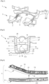
- the U-shaped section profile 9 forms a hollow body delimited by two side walls 9.1, 9.2 and a bottom wall 9.3.
- the reinforcement 11 is a structure with partitions which delimit chambers or cells 13. On the cross section of the Figure 2 , only two chambers 13 of the partitioned structure of the reinforcement 11 are in particular visible.
- This partitioned structure 11 is furthermore delimited by two opposite lateral faces 11.1, 11.2 and a bottom face 11.3.
- the two lateral faces 11.1, 11.2 are intended to be respectively opposite the lateral walls 9.1, 9.2 of the U-shaped section profile 9, and the bottom face 11.3 is intended to be opposite the bottom wall 9.3 of the same profile 9.
- This bottom face 11.3 comprises two ribs 17 which extend in the main direction of the partitioned structure 11 so as to delimit with the bottom wall 9.3 of the U-shaped section profile 9 a ventilation channel 19. Between these two ribs 17, and over at least one portion, the bottom face 11.3 further comprises a bottom wall 21 with ventilation orifices 23.
- These ventilation orifices 23 generally have an average diameter of less than 10 mm and greater than 5 mm and may be two or more in number for each chamber located opposite the face background 11.3 of the partitioned structure 11. In this case on the Figure 2 , only two ventilation orifices 23 are shown on the bottom wall 21 of the partitioned structure of the reinforcement 11.
- Vents 23 serve in particular to create a permanent circulation of air by convection between the interior of the chambers 13 concerned and the ventilation channel 19, thus allowing the drying of the hollow body(ies) of the stretchers 7.
- bottom wall 21 of the partitioned structure of the reinforcement 11 according to the invention can also extend transversely to the main direction beyond the two ribs 17 to the lateral faces 11.1, 11.2 of the structure 11.
- an expanding adhesive material 27 can also be applied between the side walls 9.1, 9.2 of the U-section profile 9 and the partitioned structure of the reinforcement 11.
- This expanding adhesive material 27 is compatible with the baking temperatures of anti-corrosion coating by cataphoresis around the reinforcement 11.
- the expandable adhesive material 27 extends in particular from the side walls 11.1, 11.2 towards the bottom wall 9.3 of the U-shaped section profile 9, and it stops at the ribs 17 of the reinforcement 11 so as to also form the ventilation channel 19.
- FIG. 3 represents a top and exploded view of a front stretcher of the front part of the vehicle of the Figure 1 , with a reinforcement according to the invention and a U-section profile which are not assembled.
- the partitioned structure of the reinforcement 11 extends, just like the U-shaped section profile 9, in a main direction forming an elbow, and that the bottom wall 21 of this structure 11 extends continuously along said elbow.
- This partitioned structure 11 is made up of several chambers or cells 13 delimited by transverse partitions 31. These chambers 13 are aligned along the main direction and can also be delimited by horizontal or oblique partitions. This is the case on the Figure 2 , where a horizontal partition 33 delimits two superimposed chambers 13.
- the horizontal partition 33 also comprises, and on at least one portion, ventilation orifices (not individually shown).
- ventilation orifices (not individually shown).
- the arrangement of these ventilation orifices makes it possible to create a second vertical and continuous air circulation between the two superimposed chambers 13 of the Figure 2 , which also contributes to the drying out over time of runoff water from the upper parts of motor vehicles 1 and/or cataphoresis fluids used during the assembly of bodywork parts.
- the bottom wall 9.3 of the U-shaped section profile 9 of the stretcher 7 comprises openings 35 along the main direction, in direct contact with the ventilation channel 19, the latter in this case not being visible on the Figure 3 but illustrated on the Figure 2 .
- the reinforcement for hollow bodies of bodywork parts has the advantage of continuously drying during the life of the vehicle, the water which may stagnate in the hollow bodies in which it is inserted, and thus improving the anti-corrosion guarantee of the coatings applied by cataphoresis during assembly of the vehicle, and in this sense of making it possible to avoid the weakening of the hollow bodywork parts.
Landscapes
- Engineering & Computer Science (AREA)
- Chemical & Material Sciences (AREA)
- Combustion & Propulsion (AREA)
- Transportation (AREA)
- Mechanical Engineering (AREA)
- Architecture (AREA)
- Structural Engineering (AREA)
- Body Structure For Vehicles (AREA)
- Blow-Moulding Or Thermoforming Of Plastics Or The Like (AREA)
Claims (9)
- Träger, umfassend:- ein U-förmiges Querschnittsprofil (9) mit zwei Seitenwänden (9.1, 9.2) und einer Bodenwand (9.3);- eine Verstärkung (11), die im U-förmigen Abschnitt des Profils (9) untergebracht ist und durch einen expandierenden Klebstoff (27) zwischen den Seitenwänden (9.1, 9.2) des U-förmigen Abschnitts (9) und der Verstärkung (11) an dem Profil (9) befestigt ist; Und- eine Platte (25), die am Profil (9) befestigt ist, um den U-förmigen Abschnitt zu schließen;wobei die Verstärkung (11) eine unterteilte Struktur bildet, die sich in einer Hauptrichtung erstreckt und zwei Seitenflächen (11.1, 11.2) gegenüber den Seitenwänden (9.1, 9.2) des Profils (9) und eine Bodenfläche (11.3) gegenüber der Bodenwand (9.3) des Profils (9) umfasst,dadurch gekennzeichnet, dassdie geteilte Struktur (11) an der Unterseite (11.3) zwei Rippen (17) aufweist, die sich in Hauptrichtung erstrecken und mit der Bodenwand (9.3) des Profils (9) einen Belüftungskanal (19) begrenzen, wobei sich der expandierbare Klebstoff (27) von den Seitenwänden (9.1, 9.2) in Richtung Bodenwand (9.3) des U-förmigen Abschnitts (9) erstreckt und an den Rippen (17) der Verstärkung (11) endet, um den Belüftungskanal (19) zu bilden, und die geteilte Struktur (11) ferner an der Unterseite (11.3) zwischen den beiden Rippen (17) und an mindestens einem Abschnitt der Struktur (11) eine Bodenwand (21) aufweist, die mit Belüftungsöffnungen (23) versehen ist.
- Träger nach Anspruch 1, dadurch gekennzeichnet, dass die Belüftungsöffnungen (23) einen durchschnittlichen Durchmesser kleiner 10 mm und größer 5 mm aufweisen.
- Träger nach einem der Ansprüche 1 und 2, dadurch gekennzeichnet, dass die Trennwände (31, 33) Kammern (13) bilden, wobei sich die Bodenwand (21) der Trennstruktur (11) in Hauptrichtung entlang mehrerer Kammern (13) erstreckt.
- Träger nach Anspruch 3, dadurch gekennzeichnet, dass bei einigen Kammern (13) die Anzahl der Belüftungsöffnungen (23) zwei oder mehr pro Kammer (13) beträgt.
- Träger nach einem der Ansprüche 1 bis 4, dadurch gekennzeichnet, dass sich die Bodenwand (21) der geteilten Struktur (11) quer zur Hauptrichtung über die beiden Rippen (17) hinaus bis zu den Seitenflächen (11.1, 11.2) dieser Struktur (11) erstreckt.
- Träger nach einem der Ansprüche 1 bis 5, dadurch gekennzeichnet, dass die Hauptrichtung einen Bogen bildet, wobei die Bodenwand (21) der Trennstruktur (11) sich durchgehend entlang dieses Bogens erstreckt.
- Träger nach einem der vorhergehenden Ansprüche, dadurch gekennzeichnet, dass die Bodenwand (9.3) des U-förmigen Abschnitts des Profils (9) entlang der Hauptrichtung Öffnungen (35) aufweist, die in direktem Kontakt mit dem Belüftungskanal (19) stehen.
- Träger nach einem der vorhergehenden Ansprüche, dadurch gekennzeichnet, dass er einen Krümmer bildet und ein Längsträger (7) eines Kraftfahrzeugs ist, der als Träger (7) bezeichnet wird.
- Kraftfahrzeug (1) umfassend:- einen Boden (5);- eine untere Frontschürze, die an einer Vorderkante des Bodens (5) befestigt ist; Und- zwei Längsstrukturträger (7), die sich unter einem vorderen Teil des Bodens (5) in Richtung eines Motorraums des Kraftfahrzeugs (1) erstrecken;dadurch gekennzeichnet, dass
jeder der beiden Längsträger (7) ist nach einem der vorhergehenden Ansprüche ausgebildet.
Applications Claiming Priority (2)
| Application Number | Priority Date | Filing Date | Title |
|---|---|---|---|
| FR1909368A FR3100019B1 (fr) | 2019-08-23 | 2019-08-23 | Renfort pour corps creux |
| PCT/FR2020/051453 WO2021038156A1 (fr) | 2019-08-23 | 2020-08-10 | Renfort pour corps creux |
Publications (2)
| Publication Number | Publication Date |
|---|---|
| EP4017789A1 EP4017789A1 (de) | 2022-06-29 |
| EP4017789B1 true EP4017789B1 (de) | 2025-05-07 |
Family
ID=68281701
Family Applications (1)
| Application Number | Title | Priority Date | Filing Date |
|---|---|---|---|
| EP20758278.4A Active EP4017789B1 (de) | 2019-08-23 | 2020-08-10 | Verstärkung für einen hohlkörper |
Country Status (4)
| Country | Link |
|---|---|
| EP (1) | EP4017789B1 (de) |
| CN (1) | CN114269634A (de) |
| FR (1) | FR3100019B1 (de) |
| WO (1) | WO2021038156A1 (de) |
Families Citing this family (2)
| Publication number | Priority date | Publication date | Assignee | Title |
|---|---|---|---|---|
| ES2351793T3 (es) † | 2004-07-28 | 2011-02-10 | The Procter And Gamble Company | Procedimiento para producir estructuras de núcleo absorbente. |
| FR3127744B1 (fr) * | 2021-10-05 | 2024-04-12 | Psa Automobiles Sa | Dispositif de renfort d’un châssis de véhicule automobile |
Family Cites Families (16)
| Publication number | Priority date | Publication date | Assignee | Title |
|---|---|---|---|---|
| US4970507A (en) | 1989-03-17 | 1990-11-13 | Gte Laboratories Incorporated | Broadband switching matrix for delay equalization and elimination of inversion |
| US6421979B1 (en) * | 1999-09-16 | 2002-07-23 | Basf Aktiengesellschaft | Composite constructional element |
| US6482486B1 (en) * | 2000-03-14 | 2002-11-19 | L&L Products | Heat activated reinforcing sleeve |
| GB2375328A (en) * | 2001-05-08 | 2002-11-13 | L & L Products | Reinforcing element for hollow structural member |
| DE10150061A1 (de) * | 2001-10-10 | 2003-05-15 | Hella Behr Fahrzeugsysteme | Metall/Kunststoff-Hybridträger für ein Fahrzeug-Frontmodul |
| DE102007025930A1 (de) * | 2007-06-02 | 2008-12-04 | Lanxess Deutschland Gmbh | Verstärkungselement für einen Fahrzeug Hohlkörper |
| US8020924B2 (en) * | 2007-12-26 | 2011-09-20 | Sika Technology Ag | Integrated reinforcing crossmember |
| EP2159109A1 (de) * | 2008-09-01 | 2010-03-03 | Sika Technology AG | Verstärkung mit Kanalentwurf |
| JP5253050B2 (ja) * | 2008-09-03 | 2013-07-31 | 日野自動車株式会社 | トラックのフレーム構造 |
| EP2251250A1 (de) * | 2009-05-05 | 2010-11-17 | Sika Technology AG | Bindung mit Klebewulsten oder -höckern |
| CN202294965U (zh) * | 2011-09-21 | 2012-07-04 | 上海同捷科技股份有限公司 | 设有加强结构的车辆前纵梁 |
| CN202608882U (zh) * | 2012-04-17 | 2012-12-19 | 北汽福田汽车股份有限公司 | U型侧梁及具有u型侧梁的焊接梁 |
| JP5768838B2 (ja) * | 2013-06-17 | 2015-08-26 | トヨタ自動車株式会社 | 車両の骨格構造 |
| JP5962627B2 (ja) * | 2013-09-27 | 2016-08-03 | トヨタ自動車株式会社 | 車体補強構造 |
| EP2899100B1 (de) * | 2014-01-27 | 2018-06-27 | MAGNA STEYR Fahrzeugtechnik AG & Co KG | Klebeverbindung und Klebeverfahren von zwei Hohlprofilen |
| EP3612436B2 (de) * | 2017-04-21 | 2025-12-24 | Sika Technology AG | Verstärkungselement |
-
2019
- 2019-08-23 FR FR1909368A patent/FR3100019B1/fr active Active
-
2020
- 2020-08-10 CN CN202080059637.1A patent/CN114269634A/zh active Pending
- 2020-08-10 WO PCT/FR2020/051453 patent/WO2021038156A1/fr not_active Ceased
- 2020-08-10 EP EP20758278.4A patent/EP4017789B1/de active Active
Also Published As
| Publication number | Publication date |
|---|---|
| FR3100019B1 (fr) | 2021-07-23 |
| CN114269634A (zh) | 2022-04-01 |
| WO2021038156A1 (fr) | 2021-03-04 |
| EP4017789A1 (de) | 2022-06-29 |
| FR3100019A1 (fr) | 2021-02-26 |
Similar Documents
| Publication | Publication Date | Title |
|---|---|---|
| EP4017789B1 (de) | Verstärkung für einen hohlkörper | |
| EP3177507B1 (de) | Fahrzeugstruktur mit verstärkung zwischen aluminiumschwelle und vorderer scharniersäule | |
| FR2619766A1 (fr) | Porte de vehicule automobile | |
| EP1227031A1 (de) | Strukturelement mit Gehäuseteil und gerippter Stützstruktur, und korrespondierendes Kraftfahrzeug | |
| EP2999619B1 (de) | Anordnung mit einem innenelement eines fahrzeugaufbaus, trennwand und sicherheitsgurteinzugshalterung | |
| WO2013079627A1 (fr) | Véhicule automobile comprenant une traverse supérieure de tablier | |
| EP4263295B1 (de) | Stossfängervorrichtung mit integriertem absorber und fahrzeug mit dieser vorrichtung | |
| WO2020193166A1 (fr) | Piece de fonderie d'un vehicule automobile | |
| EP2429879B1 (de) | Vorrichtung zur verbindung von unterböden, montagesatz und verfahren zur hybridisierung von unterböden | |
| EP2836400B1 (de) | Kraftfahrzeug mit einer vorrichtung zur verstärkung einer frontklappe | |
| FR3061698A1 (fr) | Structure de bas de caisse pour vehicule automobile | |
| FR2978085A1 (fr) | Vehicule automobile a portiere coulissante | |
| FR3081962A1 (fr) | Entretoise pour le montage d’une canalisation d’un vehicule automobile | |
| EP3536585B1 (de) | Blechpaneel, das eine verkleidung des hinteren teils der seitenfläche eines fahrzeugaufbaus und einen hinteren radkasten darstellt | |
| FR3138895A1 (fr) | Train arrière de véhicule automobile fixé sur une extension de doublure du longeronnet | |
| FR3057831A1 (fr) | Pare-chocs de vehicule automobile ayant des conduits d’air servant de renforts lateraux | |
| FR3072934B1 (fr) | Panneau de brisement pour vehicule automobile de type utilitaire et vehicule comportant un tel panneau | |
| FR3160378A1 (fr) | ensemble de plancher pour véhicule automobile | |
| EP1735207B1 (de) | Anordnung zur befestigung einer mechanischen verstärkungskomponente für ein kraftfahrzeug an einem seitenglied | |
| FR3162167A1 (fr) | Porte avant de véhicules automobiles a structure renforcée pour la protection contre les chocs latéraux | |
| FR3164439A1 (fr) | Partie structurelle latérale avant d’un véhicule automobile, à points de masse protégés | |
| WO2024189284A1 (fr) | Renfort de longeron avec deux positions de fixation selon la largeur de voie du véhicule automobile | |
| FR3074130A1 (fr) | Renfort d'une doublure de custode de vehicule automobile comprenant une ouverture de bol a carburant | |
| FR3092068A1 (fr) | Véhicule à pièces de finition couplées à sa grille d’auvent et à ses ailes avant | |
| FR2988363A1 (fr) | Cloison d'etancheite gonflante avec deux jeux de fixations pour cavite modulable de caisse de vehicule. |
Legal Events
| Date | Code | Title | Description |
|---|---|---|---|
| STAA | Information on the status of an ep patent application or granted ep patent |
Free format text: STATUS: UNKNOWN |
|
| STAA | Information on the status of an ep patent application or granted ep patent |
Free format text: STATUS: THE INTERNATIONAL PUBLICATION HAS BEEN MADE |
|
| PUAI | Public reference made under article 153(3) epc to a published international application that has entered the european phase |
Free format text: ORIGINAL CODE: 0009012 |
|
| STAA | Information on the status of an ep patent application or granted ep patent |
Free format text: STATUS: REQUEST FOR EXAMINATION WAS MADE |
|
| 17P | Request for examination filed |
Effective date: 20220214 |
|
| AK | Designated contracting states |
Kind code of ref document: A1 Designated state(s): AL AT BE BG CH CY CZ DE DK EE ES FI FR GB GR HR HU IE IS IT LI LT LU LV MC MK MT NL NO PL PT RO RS SE SI SK SM TR |
|
| DAV | Request for validation of the european patent (deleted) | ||
| DAX | Request for extension of the european patent (deleted) | ||
| RAP3 | Party data changed (applicant data changed or rights of an application transferred) |
Owner name: STELLANTIS AUTO SAS |
|
| STAA | Information on the status of an ep patent application or granted ep patent |
Free format text: STATUS: EXAMINATION IS IN PROGRESS |
|
| 17Q | First examination report despatched |
Effective date: 20240704 |
|
| GRAP | Despatch of communication of intention to grant a patent |
Free format text: ORIGINAL CODE: EPIDOSNIGR1 |
|
| STAA | Information on the status of an ep patent application or granted ep patent |
Free format text: STATUS: GRANT OF PATENT IS INTENDED |
|
| INTG | Intention to grant announced |
Effective date: 20250108 |
|
| GRAS | Grant fee paid |
Free format text: ORIGINAL CODE: EPIDOSNIGR3 |
|
| GRAA | (expected) grant |
Free format text: ORIGINAL CODE: 0009210 |
|
| STAA | Information on the status of an ep patent application or granted ep patent |
Free format text: STATUS: THE PATENT HAS BEEN GRANTED |
|
| AK | Designated contracting states |
Kind code of ref document: B1 Designated state(s): AL AT BE BG CH CY CZ DE DK EE ES FI FR GB GR HR HU IE IS IT LI LT LU LV MC MK MT NL NO PL PT RO RS SE SI SK SM TR |
|
| REG | Reference to a national code |
Ref country code: GB Ref legal event code: FG4D Free format text: NOT ENGLISH |
|
| REG | Reference to a national code |
Ref country code: CH Ref legal event code: EP |
|
| REG | Reference to a national code |
Ref country code: DE Ref legal event code: R096 Ref document number: 602020050868 Country of ref document: DE |
|
| REG | Reference to a national code |
Ref country code: IE Ref legal event code: FG4D Free format text: LANGUAGE OF EP DOCUMENT: FRENCH |
|
| REG | Reference to a national code |
Ref country code: DE Ref legal event code: R084 Ref document number: 602020050868 Country of ref document: DE |
|
| REG | Reference to a national code |
Ref country code: NL Ref legal event code: MP Effective date: 20250507 |
|
| PG25 | Lapsed in a contracting state [announced via postgrant information from national office to epo] |
Ref country code: PT Free format text: LAPSE BECAUSE OF FAILURE TO SUBMIT A TRANSLATION OF THE DESCRIPTION OR TO PAY THE FEE WITHIN THE PRESCRIBED TIME-LIMIT Effective date: 20250908 Ref country code: ES Free format text: LAPSE BECAUSE OF FAILURE TO SUBMIT A TRANSLATION OF THE DESCRIPTION OR TO PAY THE FEE WITHIN THE PRESCRIBED TIME-LIMIT Effective date: 20250507 Ref country code: FI Free format text: LAPSE BECAUSE OF FAILURE TO SUBMIT A TRANSLATION OF THE DESCRIPTION OR TO PAY THE FEE WITHIN THE PRESCRIBED TIME-LIMIT Effective date: 20250507 |
|
| PGFP | Annual fee paid to national office [announced via postgrant information from national office to epo] |
Ref country code: DE Payment date: 20250724 Year of fee payment: 6 |
|
| REG | Reference to a national code |
Ref country code: LT Ref legal event code: MG9D |
|
| PG25 | Lapsed in a contracting state [announced via postgrant information from national office to epo] |
Ref country code: NO Free format text: LAPSE BECAUSE OF FAILURE TO SUBMIT A TRANSLATION OF THE DESCRIPTION OR TO PAY THE FEE WITHIN THE PRESCRIBED TIME-LIMIT Effective date: 20250807 Ref country code: GR Free format text: LAPSE BECAUSE OF FAILURE TO SUBMIT A TRANSLATION OF THE DESCRIPTION OR TO PAY THE FEE WITHIN THE PRESCRIBED TIME-LIMIT Effective date: 20250808 |
|
| PG25 | Lapsed in a contracting state [announced via postgrant information from national office to epo] |
Ref country code: NL Free format text: LAPSE BECAUSE OF FAILURE TO SUBMIT A TRANSLATION OF THE DESCRIPTION OR TO PAY THE FEE WITHIN THE PRESCRIBED TIME-LIMIT Effective date: 20250507 Ref country code: PL Free format text: LAPSE BECAUSE OF FAILURE TO SUBMIT A TRANSLATION OF THE DESCRIPTION OR TO PAY THE FEE WITHIN THE PRESCRIBED TIME-LIMIT Effective date: 20250507 |
|
| REG | Reference to a national code |
Ref country code: AT Ref legal event code: MK05 Ref document number: 1792209 Country of ref document: AT Kind code of ref document: T Effective date: 20250507 |
|
| PG25 | Lapsed in a contracting state [announced via postgrant information from national office to epo] |
Ref country code: BG Free format text: LAPSE BECAUSE OF FAILURE TO SUBMIT A TRANSLATION OF THE DESCRIPTION OR TO PAY THE FEE WITHIN THE PRESCRIBED TIME-LIMIT Effective date: 20250507 |
|
| PG25 | Lapsed in a contracting state [announced via postgrant information from national office to epo] |
Ref country code: HR Free format text: LAPSE BECAUSE OF FAILURE TO SUBMIT A TRANSLATION OF THE DESCRIPTION OR TO PAY THE FEE WITHIN THE PRESCRIBED TIME-LIMIT Effective date: 20250507 |
|
| PG25 | Lapsed in a contracting state [announced via postgrant information from national office to epo] |
Ref country code: AT Free format text: LAPSE BECAUSE OF FAILURE TO SUBMIT A TRANSLATION OF THE DESCRIPTION OR TO PAY THE FEE WITHIN THE PRESCRIBED TIME-LIMIT Effective date: 20250507 |
|
| PGFP | Annual fee paid to national office [announced via postgrant information from national office to epo] |
Ref country code: FR Payment date: 20250725 Year of fee payment: 6 |
|
| PG25 | Lapsed in a contracting state [announced via postgrant information from national office to epo] |
Ref country code: RS Free format text: LAPSE BECAUSE OF FAILURE TO SUBMIT A TRANSLATION OF THE DESCRIPTION OR TO PAY THE FEE WITHIN THE PRESCRIBED TIME-LIMIT Effective date: 20250807 |
|
| PG25 | Lapsed in a contracting state [announced via postgrant information from national office to epo] |
Ref country code: IS Free format text: LAPSE BECAUSE OF FAILURE TO SUBMIT A TRANSLATION OF THE DESCRIPTION OR TO PAY THE FEE WITHIN THE PRESCRIBED TIME-LIMIT Effective date: 20250907 |
|
| PG25 | Lapsed in a contracting state [announced via postgrant information from national office to epo] |
Ref country code: LV Free format text: LAPSE BECAUSE OF FAILURE TO SUBMIT A TRANSLATION OF THE DESCRIPTION OR TO PAY THE FEE WITHIN THE PRESCRIBED TIME-LIMIT Effective date: 20250507 |
|
| PG25 | Lapsed in a contracting state [announced via postgrant information from national office to epo] |
Ref country code: DK Free format text: LAPSE BECAUSE OF FAILURE TO SUBMIT A TRANSLATION OF THE DESCRIPTION OR TO PAY THE FEE WITHIN THE PRESCRIBED TIME-LIMIT Effective date: 20250507 Ref country code: SM Free format text: LAPSE BECAUSE OF FAILURE TO SUBMIT A TRANSLATION OF THE DESCRIPTION OR TO PAY THE FEE WITHIN THE PRESCRIBED TIME-LIMIT Effective date: 20250507 |
|
| PG25 | Lapsed in a contracting state [announced via postgrant information from national office to epo] |
Ref country code: CZ Free format text: LAPSE BECAUSE OF FAILURE TO SUBMIT A TRANSLATION OF THE DESCRIPTION OR TO PAY THE FEE WITHIN THE PRESCRIBED TIME-LIMIT Effective date: 20250507 |
|
| PG25 | Lapsed in a contracting state [announced via postgrant information from national office to epo] |
Ref country code: EE Free format text: LAPSE BECAUSE OF FAILURE TO SUBMIT A TRANSLATION OF THE DESCRIPTION OR TO PAY THE FEE WITHIN THE PRESCRIBED TIME-LIMIT Effective date: 20250507 |
|
| PG25 | Lapsed in a contracting state [announced via postgrant information from national office to epo] |
Ref country code: RO Free format text: LAPSE BECAUSE OF FAILURE TO SUBMIT A TRANSLATION OF THE DESCRIPTION OR TO PAY THE FEE WITHIN THE PRESCRIBED TIME-LIMIT Effective date: 20250507 Ref country code: SK Free format text: LAPSE BECAUSE OF FAILURE TO SUBMIT A TRANSLATION OF THE DESCRIPTION OR TO PAY THE FEE WITHIN THE PRESCRIBED TIME-LIMIT Effective date: 20250507 |
|
| PG25 | Lapsed in a contracting state [announced via postgrant information from national office to epo] |
Ref country code: IT Free format text: LAPSE BECAUSE OF FAILURE TO SUBMIT A TRANSLATION OF THE DESCRIPTION OR TO PAY THE FEE WITHIN THE PRESCRIBED TIME-LIMIT Effective date: 20250507 |
|
| PLBI | Opposition filed |
Free format text: ORIGINAL CODE: 0009260 |